EP3248701A1 - Capture hood for an extractor hood - Google Patents
Capture hood for an extractor hood Download PDFInfo
- Publication number
- EP3248701A1 EP3248701A1 EP17020228.7A EP17020228A EP3248701A1 EP 3248701 A1 EP3248701 A1 EP 3248701A1 EP 17020228 A EP17020228 A EP 17020228A EP 3248701 A1 EP3248701 A1 EP 3248701A1
- Authority
- EP
- European Patent Office
- Prior art keywords
- detection
- hood
- edge
- detection hood
- air flow
- Prior art date
- Legal status (The legal status is an assumption and is not a legal conclusion. Google has not performed a legal analysis and makes no representation as to the accuracy of the status listed.)
- Granted
Links
Images

Classifications
-
- B—PERFORMING OPERATIONS; TRANSPORTING
- B08—CLEANING
- B08B—CLEANING IN GENERAL; PREVENTION OF FOULING IN GENERAL
- B08B15/00—Preventing escape of dirt or fumes from the area where they are produced; Collecting or removing dirt or fumes from that area
- B08B15/02—Preventing escape of dirt or fumes from the area where they are produced; Collecting or removing dirt or fumes from that area using chambers or hoods covering the area
-
- B—PERFORMING OPERATIONS; TRANSPORTING
- B08—CLEANING
- B08B—CLEANING IN GENERAL; PREVENTION OF FOULING IN GENERAL
- B08B15/00—Preventing escape of dirt or fumes from the area where they are produced; Collecting or removing dirt or fumes from that area
- B08B15/04—Preventing escape of dirt or fumes from the area where they are produced; Collecting or removing dirt or fumes from that area from a small area, e.g. a tool
-
- B—PERFORMING OPERATIONS; TRANSPORTING
- B23—MACHINE TOOLS; METAL-WORKING NOT OTHERWISE PROVIDED FOR
- B23K—SOLDERING OR UNSOLDERING; WELDING; CLADDING OR PLATING BY SOLDERING OR WELDING; CUTTING BY APPLYING HEAT LOCALLY, e.g. FLAME CUTTING; WORKING BY LASER BEAM
- B23K26/00—Working by laser beam, e.g. welding, cutting or boring
- B23K26/14—Working by laser beam, e.g. welding, cutting or boring using a fluid stream, e.g. a jet of gas, in conjunction with the laser beam; Nozzles therefor
- B23K26/142—Working by laser beam, e.g. welding, cutting or boring using a fluid stream, e.g. a jet of gas, in conjunction with the laser beam; Nozzles therefor for the removal of by-products
-
- B—PERFORMING OPERATIONS; TRANSPORTING
- B23—MACHINE TOOLS; METAL-WORKING NOT OTHERWISE PROVIDED FOR
- B23K—SOLDERING OR UNSOLDERING; WELDING; CLADDING OR PLATING BY SOLDERING OR WELDING; CUTTING BY APPLYING HEAT LOCALLY, e.g. FLAME CUTTING; WORKING BY LASER BEAM
- B23K26/00—Working by laser beam, e.g. welding, cutting or boring
- B23K26/14—Working by laser beam, e.g. welding, cutting or boring using a fluid stream, e.g. a jet of gas, in conjunction with the laser beam; Nozzles therefor
- B23K26/1462—Nozzles; Features related to nozzles
- B23K26/1464—Supply to, or discharge from, nozzles of media, e.g. gas, powder, wire
- B23K26/1476—Features inside the nozzle for feeding the fluid stream through the nozzle
-
- B—PERFORMING OPERATIONS; TRANSPORTING
- B23—MACHINE TOOLS; METAL-WORKING NOT OTHERWISE PROVIDED FOR
- B23K—SOLDERING OR UNSOLDERING; WELDING; CLADDING OR PLATING BY SOLDERING OR WELDING; CUTTING BY APPLYING HEAT LOCALLY, e.g. FLAME CUTTING; WORKING BY LASER BEAM
- B23K9/00—Arc welding or cutting
- B23K9/32—Accessories
- B23K9/325—Devices for supplying or evacuating shielding gas
-
- F—MECHANICAL ENGINEERING; LIGHTING; HEATING; WEAPONS; BLASTING
- F24—HEATING; RANGES; VENTILATING
- F24C—DOMESTIC STOVES OR RANGES ; DETAILS OF DOMESTIC STOVES OR RANGES, OF GENERAL APPLICATION
- F24C15/00—Details
- F24C15/20—Removing cooking fumes
Definitions
- the invention relates to a detection hood for a suction system with a detection opening for suction to guide a particle-laden air flow. Furthermore, the invention relates to a conversion kit for a detection hood.
- the main field of application is in the field of welding fume extraction.
- an extraction system should be used as soon as it is no longer possible to prevent hazardous substances from forming during a process.
- these substances can be detected directly at the point of origin, so as to reduce the risk to the worker to a minimum.
- these substances can be detected more or less well.
- Disadvantages are turbulences in the region of the edge of such hoods, which on the one hand disturb the air flow away from the area to be sucked off and, on the other hand, deposits can occur on the edge of the hoods.
- the object of the invention is an improved detection hood for an exhaust system or a conversion kit for an existing Detection hood to provide, in which the air flow guidance is improved.
- a detection hood for an extraction system is provided with a detection opening for suction for guiding a particle-laden air flow, wherein the detection hood is formed with a funnel-shaped or barrel-shaped base body with a predominantly outwardly directed edge, and that in or between layers of the material forming the edge at least one air passage channel is formed, which allows a secondary air flow to the inner region of the detection hood.
- the proposed detection hood at the same time the required air power and thus also coupled thereto electrical power can be reduced. It remains the filter medium used can nevertheless be regenerated to the same extent as the already existing filter elements.
- the technology also makes it possible to detect substances in areas that a conventional hood would no longer be able to detect.
- a particularly preferred embodiment of the invention provides that the air passage channel is designed slot-shaped or through a plurality of adjacent openings.
- spacer elements are arranged or formed inside the air passage channel, which connect an upper and an underside of the edge of the main body.
- the spacer elements are formed in a drop-shaped and / or streamlined shape in cross section.
- the spacer elements on the side air flow side facing round shape courses.
- top and bottom of the edge of the body or the layers forming the edge are made according to a further advantageous variant of the invention of different, different hard materials.
- the detection hood at the end of a Absaugarms which is connected to a suction system, can be connected.
- a conversion kit for a detection hood for a suction system wherein the detection hood is formed with a funnel-shaped or barrel-shaped base body with a predominantly outward edge, proposed, which is characterized in that a lower layer for attachment with Spacer elements on a lower side of an upper edge of the detection hood forming layer is configured so that forms an air passage between the upper layer and the lower layer, which allows a secondary air flow to the inner region of the detection hood.
- the spacer elements are integrally formed on the lower layer.
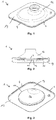
- the Fig. 1 to 3 show in different room views an exemplary detection hood 1 in particular for mounting at the end of a suction of a suction with a detection port 11 for suction to guide a particle-laden air flow 3.
- the detection hood 1 is formed with a funnel-shaped base body 12 with an outwardly directed edge 13.
- a plurality of air passage channels 4 are formed, which allows a secondary air flow 5 to the inner region 14 of the detection hood 1.
- the air passage channels 4 are designed slot-shaped.
- the detection hood or its edge can be round or angular.
- the mode of operation is fundamentally based on the Veturi effect, in which a secondary air flow is created by the passing of a primary volume flow, due to friction processes.
- the primary air flow is created in the detection hood itself.
- the entrained air of the secondary flow is sucked through the channels and thus ensures a volume flow at the slots and thus on the outside of the detection hood.
- This has the consequence that also around the detection hood around an air movement arises and not only on the suction side of the detection hood.
- the suction area can be increased significantly.
- the effect of the extended edge or flange is positively added, since at the same time also the detection radius can be increased.
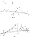
- Fig. 4 shows the forming air stream 3 and the secondary air stream 5 to the inner region 14 of the detection hood 1.
- separating elements 6 are formed, which connect a top 15 with a bottom 16 of the edge 13 of the body 12 ,
- Fig. 6 a horizontal section through an exemplary spacer 6 is shown.
- the spacer elements 6 are formed drop-shaped and streamlined in cross-section. Therefore, the spacer elements 6 on the side air flow 5 facing sides on round shape.
Landscapes
- Engineering & Computer Science (AREA)
- Physics & Mathematics (AREA)
- Optics & Photonics (AREA)
- Plasma & Fusion (AREA)
- Mechanical Engineering (AREA)
- Sampling And Sample Adjustment (AREA)
- Ventilation (AREA)
Abstract
Die Erfindung betrifft eine Erfassungshaube (1) für eine Absauganlage mit einer Erfassungsöffnung (11) zur Ansaugung zur Führung eines partikelbelasteten Luftstroms (3), wobei die Erfassungshaube (1) mit einem trichter- oder tonnenförmigen Grundkörper (12) mit einem am Ende der Haube angeordneten, im wesentlichen senkrecht zur Erfassungsrichtung des Luftstroms (3) nach außen gerichteten Rand (13) ausgebildet ist, und dass im oder zwischen Schichten des den nach außen gerichteten Rand (13) bildenden Materials wenigstens ein Luftdurchlasskanal (4) ausgebildet ist, der einen Nebenluftstrom (5) zum Innenbereich (14) der Erfassungshaube (1) ermöglicht.The invention relates to a detection hood (1) for a suction system with a detection opening (11) for suction for guiding a particle-laden air stream (3), wherein the detection hood (1) with a funnel-shaped or barrel-shaped base body (12) with one at the end of the hood arranged, substantially perpendicular to the detection direction of the air flow (3) outwardly directed edge (13) is formed, and that in or between layers of the outwardly directed edge (13) forming material at least one air passage channel (4) is formed, the one Side air flow (5) to the inner region (14) of the detection hood (1) allows.
Description
Die Erfindung betrifft eine Erfassungshaube für eine Absauganlage mit einer Erfassungsöffnung zur Ansaugung zur Führung eines partikelbelasteten Luftstroms. Des Weiteren betrifft die Erfindung einen Umbausatz für ein Erfassungshaube.The invention relates to a detection hood for a suction system with a detection opening for suction to guide a particle-laden air flow. Furthermore, the invention relates to a conversion kit for a detection hood.
Mit Hilfe einer Absauganlage in Kombination mit einer damit verbundenden und dazu passenden Erfassungshaube, können verschiedenste Partikeln erfasst und abgeschieden werden.With the help of an extraction system in combination with a matching and matching detection hood, the most diverse particles can be captured and separated.
Das Hauptanwendungsgebiet befindet sich hierbei im Bereich der Schweißrauchabsaugung. Hierbei ist eine Absaugung zu verwenden, sobald man es nicht mehr verhindern kann, dass gesundheitsgefährdende Stoffe bei einem Prozess entstehen.The main field of application is in the field of welding fume extraction. In this case, an extraction system should be used as soon as it is no longer possible to prevent hazardous substances from forming during a process.
Mit Hilfe der Hauben können diese Stoffe direkt am Entstehungsort erfasst werden, um so die Gefährdung für den Arbeiter auf ein Minimum abzusenken. Je nach Form einer Haube und Leistung der Anlage können diese Stoffe mehr-oder minder gut erfasst werden.With the help of hoods, these substances can be detected directly at the point of origin, so as to reduce the risk to the worker to a minimum. Depending on the shape of a hood and the performance of the system, these substances can be detected more or less well.
Nachteilig sind Verwirbelungen im Bereich des Randes von solchen Hauben, die zum einen den Luftstrom vom abzusaugenden Bereich weg stören und zum anderen kann es zu Ablagerungen auf dem Rand der Hauben kommen.Disadvantages are turbulences in the region of the edge of such hoods, which on the one hand disturb the air flow away from the area to be sucked off and, on the other hand, deposits can occur on the edge of the hoods.
Aufgabe der Erfindung ist es eine verbesserte Erfassungshaube für eine Absauganlage bzw. einen Umbausatz für eine bestehende Erfassungshaube bereit zu stellen, bei der die Luftstromführung verbessert ist.The object of the invention is an improved detection hood for an exhaust system or a conversion kit for an existing Detection hood to provide, in which the air flow guidance is improved.
Diese Aufgabe wird durch eine Erfassungshaube für eine Absauganlage nach den Merkmalen des Anspruchs 1 und einen Umbausatz nach den Merkmalen des Anspruchs 8 gelöst.This object is achieved by a detection hood for an extraction system according to the features of
Erfindungsgemäß ist eine Erfassungshaube für eine Absauganlage mit einer Erfassungsöffnung zur Ansaugung zur Führung eines partikelbelasteten Luftstroms vorgesehen, wobei die Erfassungshaube mit einem trichter- oder tonnenförmigen Grundkörper mit einem überwiegend nach außen gerichteten Rand ausgebildet ist, und dass im oder zwischen Schichten des den Rand bildenden Materials wenigstens ein Luftdurchlasskanal ausgebildet ist, der einen Nebenluftstrom zum Innenbereich der Erfassungshaube ermöglicht.According to the invention, a detection hood for an extraction system is provided with a detection opening for suction for guiding a particle-laden air flow, wherein the detection hood is formed with a funnel-shaped or barrel-shaped base body with a predominantly outwardly directed edge, and that in or between layers of the material forming the edge at least one air passage channel is formed, which allows a secondary air flow to the inner region of the detection hood.
Mit Hilfe einer neuartigen Erfassungshaube wird Effizienzsteigerung erzielt. Diese zeigt sich in verschiedenen Varianten.
- a) Der Erfassungsbereich wird bei gleichem Volumenstrom gesteigert
- b) Der Erfassungsbereich bleibt der gleiche, bei gleichzeitiger Senkung des Volumenstromes
- c) Der Erfassungsbereich kann gesteigert werden, bei gleichzeitiger Senkung des Volumenstromes -> maximales Ergebnis
- d) Es kann allgemein in einem Bereich erfasst werden, der vorher als "verloren" bzw. nicht gezielt absaugbar galt.
- a) The detection range is increased at the same volume flow
- b) The detection range remains the same, while reducing the volume flow
- c) The detection range can be increased while simultaneously reducing the volume flow -> maximum result
- d) It can generally be detected in an area previously considered to be "lost" or not deliberately extractable.
Zudem kann durch die vorgeschlagene Erfassungshaube zugleich die erforderliche Luftleistung und damit auch die damit gekoppelte elektrische Leistung gesenkt werden. Dabei bleibt das eingesetzte Filtermedium dennoch im gleichen Maße regenerierbar, wie die schon bestehenden Filterelemente.In addition, by the proposed detection hood at the same time the required air power and thus also coupled thereto electrical power can be reduced. It remains the filter medium used can nevertheless be regenerated to the same extent as the already existing filter elements.
Durch die Technologie wird zudem ermöglicht in Bereichen Stoffe zu erfassen, die eine herkömmliche Haube nicht mehr erfassen könnte.The technology also makes it possible to detect substances in areas that a conventional hood would no longer be able to detect.
Eine besonders bevorzugte Ausgestaltung der Erfindung sieht vor, dass der Luftdurchlasskanal schlitzförmig oder durch mehrere nebeneinanderliegende Öffnungen ausgestaltet ist.A particularly preferred embodiment of the invention provides that the air passage channel is designed slot-shaped or through a plurality of adjacent openings.
Weiterhin ist von Vorteil vorgeschlagen, dass innerhalb des Luftdurchlasskanals Abstandselemente angeordnet oder ausgeformt sind, die eine Ober- mit einer Unterseite des Rands des Grundkörpers verbinden.Furthermore, it is advantageously proposed that spacer elements are arranged or formed inside the air passage channel, which connect an upper and an underside of the edge of the main body.
Dem folgend ist von Vorteil weiterhin vorgeschlagen, dass die Abstandselemente im Querschnitt tropfenförmig und/oder stromlinienförmig ausgebildet sind.Following the following is also proposed advantageous that the spacer elements are formed in a drop-shaped and / or streamlined shape in cross section.
Von Vorteil weisen die Abstandselemente an den dem Nebenluftstrom zugewandten Seiten runde Verlaufsformen auf.Advantageously, the spacer elements on the side air flow side facing round shape courses.
Die Ober- und die Unterseite des Rands des Grundkörpers bzw. die den Rand bildenden Schichten sind nach einer weiteren vorteilhaften Variante der Erfindung aus verschiedenen, unterschiedlich harten Werkstoffen hergestellt.The top and bottom of the edge of the body or the layers forming the edge are made according to a further advantageous variant of the invention of different, different hard materials.
Bevorzugterweise ist vorgesehen, dass die Erfassungshaube am Ende eines Absaugarms, welcher mit einer Absauganlage verbunden ist, angeschlossen werden kann.Preferably, it is provided that the detection hood at the end of a Absaugarms, which is connected to a suction system, can be connected.
Nach einem weiteren Aspekt der Erfindung ist ein Umbausatz für eine Erfassungshaube für eine Absauganlage, wobei die Erfassungshaube mit einem trichter- oder tonnenförmigen Grundkörper mit einem überwiegend nach außen gerichteten Rand ausgebildet ist, vorgeschlagen, der sich dadurch auszeichnet, dass eine untere Schicht zur Befestigung mit Abstandselementen auf einer unteren Seite einer oberen den Rand der Erfassungshaube bildenden Schicht so ausgestaltet ist, dass sich zwischen der oberen Schicht und der untere Schicht ein Luftdurchlasskanal bildet, der einen Nebenluftstrom zum Innenbereich der Erfassungshaube ermöglicht.According to a further aspect of the invention, a conversion kit for a detection hood for a suction system, wherein the detection hood is formed with a funnel-shaped or barrel-shaped base body with a predominantly outward edge, proposed, which is characterized in that a lower layer for attachment with Spacer elements on a lower side of an upper edge of the detection hood forming layer is configured so that forms an air passage between the upper layer and the lower layer, which allows a secondary air flow to the inner region of the detection hood.
Dem folgend ist nach einer Variante vorgesehen, dass die Abstandselemente auf der unteren Schicht angeformt sind.The following is provided according to a variant that the spacer elements are integrally formed on the lower layer.
Weitere vorteilhafte Ausgestaltungen ergeben sich aus den weiteren Unteransprüchen oder deren mögliche Unterkombinationen.Further advantageous embodiments will become apparent from the other dependent claims or their possible sub-combinations.
Nachfolgend wird die Erfindung anhand der Zeichnungen weiter erläutert. Im Einzelnen zeigt die schematische Darstellung in:
- Fig. 1
- eine schematische Darstellung einer erfindungsgemäßen Erfassungshaube von schräg oben,
- Fig. 2
- eine schematische Darstellung der Erfassungshaube aus
Fig. 1 von der Seite, - Fig. 3
- eine schematische Darstellung der Erfassungshaube aus
Fig. 1 von schräg unten, - Fig. 4
- eine schematische Seitenansicht der Erfassungshaube aus
Fig. 1 , - Fig. 5
- eine schematische Schnittdarstellung der Erfassungshaube aus
Fig. 4 , und - Fig. 6
- eine schematische Schnittdarstellung durch ein Abstandselement im Randbereich einer Erfassungshaube.
- Fig. 1
- a schematic representation of a detection hood according to the invention obliquely from above,
- Fig. 2
- a schematic representation of the detection hood
Fig. 1 of the page, - Fig. 3
- a schematic representation of the detection hood
Fig. 1 from diagonally below, - Fig. 4
- a schematic side view of the detection hood
Fig. 1 . - Fig. 5
- a schematic sectional view of the detection hood
Fig. 4 , and - Fig. 6
- a schematic sectional view through a spacer in the edge region of a detection hood.
Die in den Figuren gleichen Bezugsziffern bezeichnen gleiche oder gleich wirkende Elemente.The same reference numerals in the figures designate the same or equivalent elements.
Die
Die Erfassungshaube bzw. deren Rand kann rund oder eckig ausgestaltet sein.The detection hood or its edge can be round or angular.
Grundlage der neu konzipierten Erfassungshaube ist ein Rand oder Flansch, der zusätzliche innenliegende "Kanäle" aufweist. Diese Luftdurchlasskanäle enden an der Innenseite der Erfassungshaube und machen sich auf der Außenseite durch "Schlitze" bemerkbar. Durch diese Schlitze kann dann im Umkehrschluss die partikelbeladene Luft angesaugt werden.The basis of the newly designed detection hood is an edge or flange, which has additional internal "channels". These air passageways end at the inside of the detection hood and make themselves noticeable on the outside by "slots". Through these slots, the particle-laden air can then be sucked in the reverse.
Zur besseren Erfassung können in diese Kanäle und Schlitze auch "Drallelemente" eingebracht werden, welche die Strömung noch zusätzlich unterstützen.For better detection and "swirl elements" can be introduced into these channels and slots, which additionally support the flow.
Die Funktionsweise basiert grundlegend auf dem Veturi-Effekt, bei dem durch das vorbeiströmen eines Primärvolumenstromes, durch Reibungsvorgänge, ein Sekundärluftstrom entsteht. In diesem Falle entsteht der Primärluftstrom in der Erfassungshaube selbst. Die mitgerissene Luft des Sekundärstromes wird durch die Kanäle gesaugt und sorgt somit für einen Volumenstrom an den Schlitzen und somit an der Außenseite der Erfassungshaube. Dies hat zur Folge, dass auch um die Erfassungshaube herum eine Luftbewegung entsteht und nicht nur an der Ansaugseite der Erfassungshaube. Somit kann der Absaugbereich merklich gesteigert werden. Der Effekt des erweiterten Randes oder Flansches kommt positiv hinzu, da dadurch gleichzeitig auch der Erfassungsradius erhöht werden kann.The mode of operation is fundamentally based on the Veturi effect, in which a secondary air flow is created by the passing of a primary volume flow, due to friction processes. In this case, the primary air flow is created in the detection hood itself. The entrained air of the secondary flow is sucked through the channels and thus ensures a volume flow at the slots and thus on the outside of the detection hood. This has the consequence that also around the detection hood around an air movement arises and not only on the suction side of the detection hood. Thus, the suction area can be increased significantly. The effect of the extended edge or flange is positively added, since at the same time also the detection radius can be increased.
Dies wird in der schematischen Schnittdarstellung durch die Erfassungshaube 1 nach
In
- 11
- Erfassungshaubecatch hood
- 1111
- Erfassungsöffnungsensing port
- 1212
- Grundkörperbody
- 1313
- Randedge
- 1414
- Innenbereichinterior
- 1515
- Oberseitetop
- 1616
- Unterseitebottom
- 33
- Luftstromairflow
- 44
- LuftdurchlasskanalVent passage
- 55
- NebenluftstromIn addition to air flow
- 66
- Abstandselementspacer
Claims (9)
dadurch gekennzeichnet,
dass die Erfassungshaube (1) mit einem trichter- oder tonnenförmigen Grundkörper (12) mit einem am Ende der Haube angeordneten, im wesentlichen senkrecht zur Erfassungsrichtung des Luftstroms (3) nach außen gerichteten Rand (13) ausgebildet ist,
und dass im oder zwischen Schichten des den nach außen gerichteten Rand (13) bildenden Materials wenigstens ein Luftdurchlasskanal (4) ausgebildet ist, der einen Nebenluftstrom (5) zum Innenbereich (14) der Erfassungshaube (1) ermöglicht.Detection hood (1) for an exhaust system with a detection opening (11) for suction to guide a particle-laden air stream (3),
characterized,
in that the detection hood (1) is designed with a funnel-shaped or barrel-shaped base body (12) with an edge (13) arranged at the end of the hood and directed essentially perpendicular to the detection direction of the air flow (3),
and that in or between layers of the outwardly directed edge (13) forming material at least one air passage channel (4) is formed, which allows a secondary air flow (5) to the inner region (14) of the detection hood (1).
dadurch gekennzeichnet,
dass der Luftdurchlasskanal (4) schlitzförmig oder durch mehrere nebeneinanderliegende Öffnungen in der äußeren Kante des nach außen, senkrecht zur Erfassungsrichtung des Luftstroms (3), ausgeformten Rands (13) ausgestaltet ist.Detection hood for an extraction system according to claim 1,
characterized,
in that the air passage channel (4) is configured in the shape of a slot or by several juxtaposed openings in the outer edge of the edge (13) formed outwards, perpendicular to the detection direction of the air flow (3).
dadurch gekennzeichnet,
dass innerhalb des Luftdurchlasskanals (4), bzw. mehrere Luftdurchlasskanäle 4 abtrennend, Abstandselemente (6) angeordnet oder ausgeformt sind, die eine Ober- (15) mit einer Unterseite (16) des Rands (13) des Grundkörpers (12) verbinden.Detection hood for an extraction system according to claim 1 or 2,
characterized,
that inside the air passage channel (4), or a plurality of air passage channels 4 separating, spacer elements (6) are arranged or formed, which connect a top (15) with a bottom (16) of the edge (13) of the base body (12).
dadurch gekennzeichnet,
dass die Abstandselemente (6) im Querschnitt tropfenförmig und/oder stromlinienförmig ausgebildet sind.Detection hood for an extraction system according to claim 3,
characterized,
that the spacer elements (6) are drop-shaped and / or streamlined in cross section.
dadurch gekennzeichnet,
dass die Abstandselemente (6) an den dem Nebenluftstrom (5) zugewandten Seiten runde Verlaufsformen aufweisen.Detection hood for an extraction system according to one of claims 3 or 4,
characterized,
that the spacer elements (6) to the secondary air stream (5) facing sides have round progressive forms.
dadurch gekennzeichnet,
dass die Ober- (15) und die Unterseite (16) des Rands (13) des Grundkörpers (12) bzw. die den Rand (13) bildenden Schichten aus verschiedenen, unterschiedlich harten Werkstoffen hergestellt sind.Detection hood for an extraction system according to one of claims 3 to 5,
characterized,
in that the upper (15) and the lower side (16) of the edge (13) of the main body (12) or the layers (13) forming the edge (13) are made of different, differently hard materials.
dadurch gekennzeichnet,
dass die Erfassungshaube (1) am Ende eines Absaugarms, welcher mit einer Absauganlage verbunden ist, angeschlossen werden kann.Detection hood for an extraction system according to one of claims 1 to 6,
characterized,
that the extraction hood (1) can be at the end of a suction arm, which is connected to a suction system, connected.
dadurch gekennzeichnet,
dass eine untere Schicht zur Befestigung mit Abstandselementen (6) auf einer unteren Seite einer oberen den Rand (13) der Erfassungshaube (1) bildenden Schicht so ausgestaltet ist, dass sich zwischen der oberen Schicht und der untere Schicht ein Luftdurchlasskanal (4) bildet, der einen Nebenluftstrom (5) zum Innenbereich (14) der Erfassungshaube (1) ermöglicht.Conversion kit for a detection hood (1) for a suction system, wherein the detection hood (1) with a funnel or barrel-shaped base body (12) is formed with a predominantly outwardly directed edge (13),
characterized,
that a lower layer to be fixed with distance elements (6) on a lower side of a top of the edge (13) of the detection cover (1) forming layer is designed so as to form a vent passage (4) between the upper layer and the lower layer, which allows a secondary air flow (5) to the inner region (14) of the detection hood (1).
dadurch gekennzeichnet,
dass die Abstandselemente (6) auf der unteren Schicht angeformt sind.Conversion kit for a detection hood according to claim 8,
characterized,
that the spacer elements (6) are integrally formed on the lower layer.
Priority Applications (1)
| Application Number | Priority Date | Filing Date | Title |
|---|---|---|---|
| PL17020228T PL3248701T3 (en) | 2016-05-27 | 2017-05-26 | Capture hood for an extractor hood |
Applications Claiming Priority (1)
| Application Number | Priority Date | Filing Date | Title |
|---|---|---|---|
| DE102016109804.3A DE102016109804B3 (en) | 2016-05-27 | 2016-05-27 | Detection hood for an extraction system |
Publications (2)
| Publication Number | Publication Date |
|---|---|
| EP3248701A1 true EP3248701A1 (en) | 2017-11-29 |
| EP3248701B1 EP3248701B1 (en) | 2019-08-21 |
Family
ID=58994600
Family Applications (1)
| Application Number | Title | Priority Date | Filing Date |
|---|---|---|---|
| EP17020228.7A Active EP3248701B1 (en) | 2016-05-27 | 2017-05-26 | Capture hood for an extractor hood |
Country Status (4)
| Country | Link |
|---|---|
| EP (1) | EP3248701B1 (en) |
| DE (1) | DE102016109804B3 (en) |
| LT (1) | LT3248701T (en) |
| PL (1) | PL3248701T3 (en) |
Cited By (1)
| Publication number | Priority date | Publication date | Assignee | Title |
|---|---|---|---|---|
| CN110860838A (en) * | 2018-08-27 | 2020-03-06 | 宁波方太厨具有限公司 | Positioning fixture for welding oil cup |
Citations (7)
| Publication number | Priority date | Publication date | Assignee | Title |
|---|---|---|---|---|
| CA890112A (en) * | 1972-01-11 | The Budd Company | Method of fabricating a brake disk | |
| GB1506886A (en) * | 1976-07-26 | 1978-04-12 | Cleen Flo Ltd | Devices for exhausting fumes or dust from work stations |
| EP0423785A2 (en) * | 1989-10-19 | 1991-04-24 | Osaka Gas Co., Ltd. | Method for removal of sprayed-on asbestos and apparatus therefor |
| US5536206A (en) * | 1995-02-10 | 1996-07-16 | Airflow Systems, Inc. | Articulated duct fume collection and exhaust apparatus |
| EP1016803A2 (en) * | 1998-12-28 | 2000-07-05 | Shimano Inc. | Method of manufacturing a ventilated brake disc |
| US20130263403A1 (en) * | 2012-03-14 | 2013-10-10 | Thomas J. Agorichas | System and method for cleaning refrigeration coils and the like |
| CN203265226U (en) * | 2013-05-17 | 2013-11-06 | 王军 | Lamp type air purification kit and air purifier |
-
2016
- 2016-05-27 DE DE102016109804.3A patent/DE102016109804B3/en active Active
-
2017
- 2017-05-26 PL PL17020228T patent/PL3248701T3/en unknown
- 2017-05-26 EP EP17020228.7A patent/EP3248701B1/en active Active
- 2017-05-26 LT LTEP17020228.7T patent/LT3248701T/en unknown
Patent Citations (7)
| Publication number | Priority date | Publication date | Assignee | Title |
|---|---|---|---|---|
| CA890112A (en) * | 1972-01-11 | The Budd Company | Method of fabricating a brake disk | |
| GB1506886A (en) * | 1976-07-26 | 1978-04-12 | Cleen Flo Ltd | Devices for exhausting fumes or dust from work stations |
| EP0423785A2 (en) * | 1989-10-19 | 1991-04-24 | Osaka Gas Co., Ltd. | Method for removal of sprayed-on asbestos and apparatus therefor |
| US5536206A (en) * | 1995-02-10 | 1996-07-16 | Airflow Systems, Inc. | Articulated duct fume collection and exhaust apparatus |
| EP1016803A2 (en) * | 1998-12-28 | 2000-07-05 | Shimano Inc. | Method of manufacturing a ventilated brake disc |
| US20130263403A1 (en) * | 2012-03-14 | 2013-10-10 | Thomas J. Agorichas | System and method for cleaning refrigeration coils and the like |
| CN203265226U (en) * | 2013-05-17 | 2013-11-06 | 王军 | Lamp type air purification kit and air purifier |
Cited By (1)
| Publication number | Priority date | Publication date | Assignee | Title |
|---|---|---|---|---|
| CN110860838A (en) * | 2018-08-27 | 2020-03-06 | 宁波方太厨具有限公司 | Positioning fixture for welding oil cup |
Also Published As
| Publication number | Publication date |
|---|---|
| DE102016109804B3 (en) | 2017-06-22 |
| EP3248701B1 (en) | 2019-08-21 |
| LT3248701T (en) | 2019-10-10 |
| PL3248701T3 (en) | 2019-12-31 |
Similar Documents
| Publication | Publication Date | Title |
|---|---|---|
| EP3282197B1 (en) | Cooktop with steam extractor | |
| EP1705430B1 (en) | Extracting hood with grease filter | |
| DE102005031420B4 (en) | Combined immersion / flat suction rotary pump with concentric impeller inlet opening | |
| EP2265868B1 (en) | Filter unit for a vapor removal apparatus and vapor removal apparatus | |
| DE19613513A1 (en) | Process for limiting, detecting and extracting haze, dust or the like and device for carrying out the process | |
| DE102016106925A1 (en) | Blow-by gas channel structure | |
| DE102008044184A1 (en) | Turbulence separation device for use in vacuum cleaner, has blocking element arranged between tube opening and front wall and including outer surface that shrinks steplessly in direction to front wall of space gradually up to upper section | |
| EP2334988B1 (en) | Extractor hood | |
| EP2772695B1 (en) | Extractor hood | |
| EP2326227B1 (en) | Vacuum cleaner and insert part of a vacuum cleaner | |
| EP3248701B1 (en) | Capture hood for an extractor hood | |
| EP2857758A1 (en) | Vapor extraction device | |
| EP3620721A1 (en) | Device for conduit extraction of exhaust air generated on a cooking hob | |
| DE102011101765A1 (en) | Device for separating water from the combustion air to be supplied to an internal combustion engine | |
| EP2689703A1 (en) | Dust extraction unit with filter cleaning | |
| DE102005013806A1 (en) | Extractor hood has suction fan and a flow direction element rotatable in suction area about rotational axis perpendicular to plane of same for improved vapour collection | |
| DE102008053164B4 (en) | Fan for a gas purification system | |
| DE2738850C2 (en) | ||
| DE4245014C2 (en) | Exhaust gas detection hood with stabilized swirl flow | |
| DE102008041228A1 (en) | vacuum cleaner | |
| AT525252B1 (en) | separating device | |
| DE102017126076A1 (en) | catch hood | |
| DE102005062525A1 (en) | Cyclone particulates separator for aspirated housings of dry-operating metal working and welding machines | |
| DE2407796A1 (en) | Ventilator with centrifugal fan inside spiral housing - has air deflection baffles guiding air through two side vents | |
| DE102017201331A1 (en) | Blower for extractor and extractor fan |
Legal Events
| Date | Code | Title | Description |
|---|---|---|---|
| PUAI | Public reference made under article 153(3) epc to a published international application that has entered the european phase |
Free format text: ORIGINAL CODE: 0009012 |
|
| STAA | Information on the status of an ep patent application or granted ep patent |
Free format text: STATUS: THE APPLICATION HAS BEEN PUBLISHED |
|
| AK | Designated contracting states |
Kind code of ref document: A1 Designated state(s): AL AT BE BG CH CY CZ DE DK EE ES FI FR GB GR HR HU IE IS IT LI LT LU LV MC MK MT NL NO PL PT RO RS SE SI SK SM TR |
|
| AX | Request for extension of the european patent |
Extension state: BA ME |
|
| STAA | Information on the status of an ep patent application or granted ep patent |
Free format text: STATUS: REQUEST FOR EXAMINATION WAS MADE |
|
| 17P | Request for examination filed |
Effective date: 20180524 |
|
| RBV | Designated contracting states (corrected) |
Designated state(s): AL AT BE BG CH CY CZ DE DK EE ES FI FR GB GR HR HU IE IS IT LI LT LU LV MC MK MT NL NO PL PT RO RS SE SI SK SM TR |
|
| GRAP | Despatch of communication of intention to grant a patent |
Free format text: ORIGINAL CODE: EPIDOSNIGR1 |
|
| STAA | Information on the status of an ep patent application or granted ep patent |
Free format text: STATUS: GRANT OF PATENT IS INTENDED |
|
| RIC1 | Information provided on ipc code assigned before grant |
Ipc: B08B 15/04 20060101AFI20190411BHEP Ipc: B08B 15/02 20060101ALI20190411BHEP Ipc: B23K 9/32 20060101ALI20190411BHEP Ipc: B23K 26/142 20140101ALI20190411BHEP Ipc: F24C 15/20 20060101ALN20190411BHEP Ipc: B23K 26/14 20140101ALI20190411BHEP |
|
| RIC1 | Information provided on ipc code assigned before grant |
Ipc: F24C 15/20 20060101ALN20190418BHEP Ipc: B23K 26/14 20140101ALI20190418BHEP Ipc: B23K 9/32 20060101ALI20190418BHEP Ipc: B23K 26/142 20140101ALI20190418BHEP Ipc: B08B 15/04 20060101AFI20190418BHEP Ipc: B08B 15/02 20060101ALI20190418BHEP |
|
| INTG | Intention to grant announced |
Effective date: 20190509 |
|
| RIC1 | Information provided on ipc code assigned before grant |
Ipc: F24C 15/20 20060101ALN20190426BHEP Ipc: B23K 26/142 20140101ALI20190426BHEP Ipc: B23K 26/14 20140101ALI20190426BHEP Ipc: B23K 9/32 20060101ALI20190426BHEP Ipc: B08B 15/04 20060101AFI20190426BHEP Ipc: B08B 15/02 20060101ALI20190426BHEP |
|
| GRAS | Grant fee paid |
Free format text: ORIGINAL CODE: EPIDOSNIGR3 |
|
| GRAA | (expected) grant |
Free format text: ORIGINAL CODE: 0009210 |
|
| STAA | Information on the status of an ep patent application or granted ep patent |
Free format text: STATUS: THE PATENT HAS BEEN GRANTED |
|
| AK | Designated contracting states |
Kind code of ref document: B1 Designated state(s): AL AT BE BG CH CY CZ DE DK EE ES FI FR GB GR HR HU IE IS IT LI LT LU LV MC MK MT NL NO PL PT RO RS SE SI SK SM TR |
|
| REG | Reference to a national code |
Ref country code: GB Ref legal event code: FG4D Free format text: NOT ENGLISH |
|
| REG | Reference to a national code |
Ref country code: CH Ref legal event code: EP |
|
| REG | Reference to a national code |
Ref country code: DE Ref legal event code: R096 Ref document number: 502017002052 Country of ref document: DE |
|
| REG | Reference to a national code |
Ref country code: AT Ref legal event code: REF Ref document number: 1169107 Country of ref document: AT Kind code of ref document: T Effective date: 20190915 |
|
| REG | Reference to a national code |
Ref country code: IE Ref legal event code: FG4D Free format text: LANGUAGE OF EP DOCUMENT: GERMAN |
|
| REG | Reference to a national code |
Ref country code: EE Ref legal event code: FG4A Ref document number: E018094 Country of ref document: EE Effective date: 20190925 |
|
| REG | Reference to a national code |
Ref country code: CH Ref legal event code: NV Representative=s name: MEYER AND KOLLEGEN, CH |
|
| REG | Reference to a national code |
Ref country code: NL Ref legal event code: FP |
|
| PG25 | Lapsed in a contracting state [announced via postgrant information from national office to epo] |
Ref country code: PT Free format text: LAPSE BECAUSE OF FAILURE TO SUBMIT A TRANSLATION OF THE DESCRIPTION OR TO PAY THE FEE WITHIN THE PRESCRIBED TIME-LIMIT Effective date: 20191223 Ref country code: NO Free format text: LAPSE BECAUSE OF FAILURE TO SUBMIT A TRANSLATION OF THE DESCRIPTION OR TO PAY THE FEE WITHIN THE PRESCRIBED TIME-LIMIT Effective date: 20191121 Ref country code: HR Free format text: LAPSE BECAUSE OF FAILURE TO SUBMIT A TRANSLATION OF THE DESCRIPTION OR TO PAY THE FEE WITHIN THE PRESCRIBED TIME-LIMIT Effective date: 20190821 Ref country code: SE Free format text: LAPSE BECAUSE OF FAILURE TO SUBMIT A TRANSLATION OF THE DESCRIPTION OR TO PAY THE FEE WITHIN THE PRESCRIBED TIME-LIMIT Effective date: 20190821 Ref country code: FI Free format text: LAPSE BECAUSE OF FAILURE TO SUBMIT A TRANSLATION OF THE DESCRIPTION OR TO PAY THE FEE WITHIN THE PRESCRIBED TIME-LIMIT Effective date: 20190821 Ref country code: BG Free format text: LAPSE BECAUSE OF FAILURE TO SUBMIT A TRANSLATION OF THE DESCRIPTION OR TO PAY THE FEE WITHIN THE PRESCRIBED TIME-LIMIT Effective date: 20191121 |
|
| PG25 | Lapsed in a contracting state [announced via postgrant information from national office to epo] |
Ref country code: AL Free format text: LAPSE BECAUSE OF FAILURE TO SUBMIT A TRANSLATION OF THE DESCRIPTION OR TO PAY THE FEE WITHIN THE PRESCRIBED TIME-LIMIT Effective date: 20190821 Ref country code: ES Free format text: LAPSE BECAUSE OF FAILURE TO SUBMIT A TRANSLATION OF THE DESCRIPTION OR TO PAY THE FEE WITHIN THE PRESCRIBED TIME-LIMIT Effective date: 20190821 Ref country code: GR Free format text: LAPSE BECAUSE OF FAILURE TO SUBMIT A TRANSLATION OF THE DESCRIPTION OR TO PAY THE FEE WITHIN THE PRESCRIBED TIME-LIMIT Effective date: 20191122 Ref country code: IS Free format text: LAPSE BECAUSE OF FAILURE TO SUBMIT A TRANSLATION OF THE DESCRIPTION OR TO PAY THE FEE WITHIN THE PRESCRIBED TIME-LIMIT Effective date: 20191221 Ref country code: RS Free format text: LAPSE BECAUSE OF FAILURE TO SUBMIT A TRANSLATION OF THE DESCRIPTION OR TO PAY THE FEE WITHIN THE PRESCRIBED TIME-LIMIT Effective date: 20190821 |
|
| PG25 | Lapsed in a contracting state [announced via postgrant information from national office to epo] |
Ref country code: IT Free format text: LAPSE BECAUSE OF FAILURE TO SUBMIT A TRANSLATION OF THE DESCRIPTION OR TO PAY THE FEE WITHIN THE PRESCRIBED TIME-LIMIT Effective date: 20190821 Ref country code: RO Free format text: LAPSE BECAUSE OF FAILURE TO SUBMIT A TRANSLATION OF THE DESCRIPTION OR TO PAY THE FEE WITHIN THE PRESCRIBED TIME-LIMIT Effective date: 20190821 Ref country code: DK Free format text: LAPSE BECAUSE OF FAILURE TO SUBMIT A TRANSLATION OF THE DESCRIPTION OR TO PAY THE FEE WITHIN THE PRESCRIBED TIME-LIMIT Effective date: 20190821 |
|
| PG25 | Lapsed in a contracting state [announced via postgrant information from national office to epo] |
Ref country code: IS Free format text: LAPSE BECAUSE OF FAILURE TO SUBMIT A TRANSLATION OF THE DESCRIPTION OR TO PAY THE FEE WITHIN THE PRESCRIBED TIME-LIMIT Effective date: 20200224 Ref country code: SM Free format text: LAPSE BECAUSE OF FAILURE TO SUBMIT A TRANSLATION OF THE DESCRIPTION OR TO PAY THE FEE WITHIN THE PRESCRIBED TIME-LIMIT Effective date: 20190821 Ref country code: SK Free format text: LAPSE BECAUSE OF FAILURE TO SUBMIT A TRANSLATION OF THE DESCRIPTION OR TO PAY THE FEE WITHIN THE PRESCRIBED TIME-LIMIT Effective date: 20190821 |
|
| REG | Reference to a national code |
Ref country code: DE Ref legal event code: R097 Ref document number: 502017002052 Country of ref document: DE |
|
| PLBE | No opposition filed within time limit |
Free format text: ORIGINAL CODE: 0009261 |
|
| STAA | Information on the status of an ep patent application or granted ep patent |
Free format text: STATUS: NO OPPOSITION FILED WITHIN TIME LIMIT |
|
| PG2D | Information on lapse in contracting state deleted |
Ref country code: IS |
|
| 26N | No opposition filed |
Effective date: 20200603 |
|
| PG25 | Lapsed in a contracting state [announced via postgrant information from national office to epo] |
Ref country code: SI Free format text: LAPSE BECAUSE OF FAILURE TO SUBMIT A TRANSLATION OF THE DESCRIPTION OR TO PAY THE FEE WITHIN THE PRESCRIBED TIME-LIMIT Effective date: 20190821 |
|
| REG | Reference to a national code |
Ref country code: EE Ref legal event code: MM4A Ref document number: E018094 Country of ref document: EE Effective date: 20200531 |
|
| REG | Reference to a national code |
Ref country code: LT Ref legal event code: MM4D Effective date: 20200526 |
|
| PG25 | Lapsed in a contracting state [announced via postgrant information from national office to epo] |
Ref country code: MC Free format text: LAPSE BECAUSE OF FAILURE TO SUBMIT A TRANSLATION OF THE DESCRIPTION OR TO PAY THE FEE WITHIN THE PRESCRIBED TIME-LIMIT Effective date: 20190821 Ref country code: EE Free format text: LAPSE BECAUSE OF NON-PAYMENT OF DUE FEES Effective date: 20200531 Ref country code: LT Free format text: LAPSE BECAUSE OF NON-PAYMENT OF DUE FEES Effective date: 20200526 |
|
| PG25 | Lapsed in a contracting state [announced via postgrant information from national office to epo] |
Ref country code: LV Free format text: LAPSE BECAUSE OF NON-PAYMENT OF DUE FEES Effective date: 20200526 |
|
| PG25 | Lapsed in a contracting state [announced via postgrant information from national office to epo] |
Ref country code: LU Free format text: LAPSE BECAUSE OF NON-PAYMENT OF DUE FEES Effective date: 20200526 |
|
| PG25 | Lapsed in a contracting state [announced via postgrant information from national office to epo] |
Ref country code: MT Free format text: LAPSE BECAUSE OF FAILURE TO SUBMIT A TRANSLATION OF THE DESCRIPTION OR TO PAY THE FEE WITHIN THE PRESCRIBED TIME-LIMIT Effective date: 20190821 Ref country code: CY Free format text: LAPSE BECAUSE OF FAILURE TO SUBMIT A TRANSLATION OF THE DESCRIPTION OR TO PAY THE FEE WITHIN THE PRESCRIBED TIME-LIMIT Effective date: 20190821 |
|
| REG | Reference to a national code |
Ref country code: DE Ref legal event code: R082 Ref document number: 502017002052 Country of ref document: DE Representative=s name: MICHALSKI HUETTERMANN & PARTNER PATENTANWAELTE, DE |
|
| PG25 | Lapsed in a contracting state [announced via postgrant information from national office to epo] |
Ref country code: MK Free format text: LAPSE BECAUSE OF FAILURE TO SUBMIT A TRANSLATION OF THE DESCRIPTION OR TO PAY THE FEE WITHIN THE PRESCRIBED TIME-LIMIT Effective date: 20190821 |
|
| PGFP | Annual fee paid to national office [announced via postgrant information from national office to epo] |
Ref country code: NL Payment date: 20230519 Year of fee payment: 7 Ref country code: IE Payment date: 20230522 Year of fee payment: 7 Ref country code: FR Payment date: 20230526 Year of fee payment: 7 Ref country code: DE Payment date: 20220628 Year of fee payment: 7 Ref country code: CZ Payment date: 20230523 Year of fee payment: 7 Ref country code: CH Payment date: 20230605 Year of fee payment: 7 |
|
| PGFP | Annual fee paid to national office [announced via postgrant information from national office to epo] |
Ref country code: PL Payment date: 20230420 Year of fee payment: 7 Ref country code: AT Payment date: 20230522 Year of fee payment: 7 |
|
| PGFP | Annual fee paid to national office [announced via postgrant information from national office to epo] |
Ref country code: BE Payment date: 20230519 Year of fee payment: 7 |
|
| PGFP | Annual fee paid to national office [announced via postgrant information from national office to epo] |
Ref country code: GB Payment date: 20230524 Year of fee payment: 7 |