EP3248548A2 - Schnellgangprävention für spreizanker - Google Patents
Schnellgangprävention für spreizanker Download PDFInfo
- Publication number
- EP3248548A2 EP3248548A2 EP17172946.0A EP17172946A EP3248548A2 EP 3248548 A2 EP3248548 A2 EP 3248548A2 EP 17172946 A EP17172946 A EP 17172946A EP 3248548 A2 EP3248548 A2 EP 3248548A2
- Authority
- EP
- European Patent Office
- Prior art keywords
- sheath
- expander screw
- inner shaft
- screw
- expander
- Prior art date
- Legal status (The legal status is an assumption and is not a legal conclusion. Google has not performed a legal analysis and makes no representation as to the accuracy of the status listed.)
- Granted
Links
Images


Classifications
-
- A—HUMAN NECESSITIES
- A61—MEDICAL OR VETERINARY SCIENCE; HYGIENE
- A61B—DIAGNOSIS; SURGERY; IDENTIFICATION
- A61B17/00—Surgical instruments, devices or methods
- A61B17/04—Surgical instruments, devices or methods for suturing wounds; Holders or packages for needles or suture materials
- A61B17/0401—Suture anchors, buttons or pledgets, i.e. means for attaching sutures to bone, cartilage or soft tissue; Instruments for applying or removing suture anchors
-
- A—HUMAN NECESSITIES
- A61—MEDICAL OR VETERINARY SCIENCE; HYGIENE
- A61F—FILTERS IMPLANTABLE INTO BLOOD VESSELS; PROSTHESES; DEVICES PROVIDING PATENCY TO, OR PREVENTING COLLAPSING OF, TUBULAR STRUCTURES OF THE BODY, e.g. STENTS; ORTHOPAEDIC, NURSING OR CONTRACEPTIVE DEVICES; FOMENTATION; TREATMENT OR PROTECTION OF EYES OR EARS; BANDAGES, DRESSINGS OR ABSORBENT PADS; FIRST-AID KITS
- A61F2/00—Filters implantable into blood vessels; Prostheses, i.e. artificial substitutes or replacements for parts of the body; Appliances for connecting them with the body; Devices providing patency to, or preventing collapsing of, tubular structures of the body, e.g. stents
- A61F2/02—Prostheses implantable into the body
- A61F2/08—Muscles; Tendons; Ligaments
- A61F2/0811—Fixation devices for tendons or ligaments
-
- A—HUMAN NECESSITIES
- A61—MEDICAL OR VETERINARY SCIENCE; HYGIENE
- A61B—DIAGNOSIS; SURGERY; IDENTIFICATION
- A61B17/00—Surgical instruments, devices or methods
- A61B2017/00004—(bio)absorbable, (bio)resorbable or resorptive
-
- A—HUMAN NECESSITIES
- A61—MEDICAL OR VETERINARY SCIENCE; HYGIENE
- A61B—DIAGNOSIS; SURGERY; IDENTIFICATION
- A61B17/00—Surgical instruments, devices or methods
- A61B17/04—Surgical instruments, devices or methods for suturing wounds; Holders or packages for needles or suture materials
- A61B17/0401—Suture anchors, buttons or pledgets, i.e. means for attaching sutures to bone, cartilage or soft tissue; Instruments for applying or removing suture anchors
- A61B2017/0403—Dowels
-
- A—HUMAN NECESSITIES
- A61—MEDICAL OR VETERINARY SCIENCE; HYGIENE
- A61B—DIAGNOSIS; SURGERY; IDENTIFICATION
- A61B17/00—Surgical instruments, devices or methods
- A61B17/04—Surgical instruments, devices or methods for suturing wounds; Holders or packages for needles or suture materials
- A61B17/0401—Suture anchors, buttons or pledgets, i.e. means for attaching sutures to bone, cartilage or soft tissue; Instruments for applying or removing suture anchors
- A61B2017/0408—Rivets
-
- A—HUMAN NECESSITIES
- A61—MEDICAL OR VETERINARY SCIENCE; HYGIENE
- A61B—DIAGNOSIS; SURGERY; IDENTIFICATION
- A61B17/00—Surgical instruments, devices or methods
- A61B17/04—Surgical instruments, devices or methods for suturing wounds; Holders or packages for needles or suture materials
- A61B17/0401—Suture anchors, buttons or pledgets, i.e. means for attaching sutures to bone, cartilage or soft tissue; Instruments for applying or removing suture anchors
- A61B2017/0409—Instruments for applying suture anchors
-
- A—HUMAN NECESSITIES
- A61—MEDICAL OR VETERINARY SCIENCE; HYGIENE
- A61B—DIAGNOSIS; SURGERY; IDENTIFICATION
- A61B17/00—Surgical instruments, devices or methods
- A61B17/04—Surgical instruments, devices or methods for suturing wounds; Holders or packages for needles or suture materials
- A61B17/0401—Suture anchors, buttons or pledgets, i.e. means for attaching sutures to bone, cartilage or soft tissue; Instruments for applying or removing suture anchors
- A61B2017/0412—Suture anchors, buttons or pledgets, i.e. means for attaching sutures to bone, cartilage or soft tissue; Instruments for applying or removing suture anchors having anchoring barbs or pins extending outwardly from suture anchor body
-
- A—HUMAN NECESSITIES
- A61—MEDICAL OR VETERINARY SCIENCE; HYGIENE
- A61B—DIAGNOSIS; SURGERY; IDENTIFICATION
- A61B17/00—Surgical instruments, devices or methods
- A61B17/04—Surgical instruments, devices or methods for suturing wounds; Holders or packages for needles or suture materials
- A61B17/0401—Suture anchors, buttons or pledgets, i.e. means for attaching sutures to bone, cartilage or soft tissue; Instruments for applying or removing suture anchors
- A61B2017/042—Suture anchors, buttons or pledgets, i.e. means for attaching sutures to bone, cartilage or soft tissue; Instruments for applying or removing suture anchors plastically deformed during insertion
- A61B2017/0422—Suture anchors, buttons or pledgets, i.e. means for attaching sutures to bone, cartilage or soft tissue; Instruments for applying or removing suture anchors plastically deformed during insertion by insertion of a separate member into the body of the anchor
- A61B2017/0424—Suture anchors, buttons or pledgets, i.e. means for attaching sutures to bone, cartilage or soft tissue; Instruments for applying or removing suture anchors plastically deformed during insertion by insertion of a separate member into the body of the anchor the separate member staying in the anchor after placement
-
- A—HUMAN NECESSITIES
- A61—MEDICAL OR VETERINARY SCIENCE; HYGIENE
- A61B—DIAGNOSIS; SURGERY; IDENTIFICATION
- A61B17/00—Surgical instruments, devices or methods
- A61B17/04—Surgical instruments, devices or methods for suturing wounds; Holders or packages for needles or suture materials
- A61B17/0401—Suture anchors, buttons or pledgets, i.e. means for attaching sutures to bone, cartilage or soft tissue; Instruments for applying or removing suture anchors
- A61B2017/042—Suture anchors, buttons or pledgets, i.e. means for attaching sutures to bone, cartilage or soft tissue; Instruments for applying or removing suture anchors plastically deformed during insertion
- A61B2017/0422—Suture anchors, buttons or pledgets, i.e. means for attaching sutures to bone, cartilage or soft tissue; Instruments for applying or removing suture anchors plastically deformed during insertion by insertion of a separate member into the body of the anchor
- A61B2017/0425—Suture anchors, buttons or pledgets, i.e. means for attaching sutures to bone, cartilage or soft tissue; Instruments for applying or removing suture anchors plastically deformed during insertion by insertion of a separate member into the body of the anchor the anchor or the separate member comprising threads, e.g. a set screw in the anchor
-
- A—HUMAN NECESSITIES
- A61—MEDICAL OR VETERINARY SCIENCE; HYGIENE
- A61B—DIAGNOSIS; SURGERY; IDENTIFICATION
- A61B17/00—Surgical instruments, devices or methods
- A61B17/04—Surgical instruments, devices or methods for suturing wounds; Holders or packages for needles or suture materials
- A61B17/0401—Suture anchors, buttons or pledgets, i.e. means for attaching sutures to bone, cartilage or soft tissue; Instruments for applying or removing suture anchors
- A61B2017/0464—Suture anchors, buttons or pledgets, i.e. means for attaching sutures to bone, cartilage or soft tissue; Instruments for applying or removing suture anchors for soft tissue
-
- A—HUMAN NECESSITIES
- A61—MEDICAL OR VETERINARY SCIENCE; HYGIENE
- A61B—DIAGNOSIS; SURGERY; IDENTIFICATION
- A61B90/00—Instruments, implements or accessories specially adapted for surgery or diagnosis and not covered by any of the groups A61B1/00 - A61B50/00, e.g. for luxation treatment or for protecting wound edges
- A61B90/03—Automatic limiting or abutting means, e.g. for safety
- A61B2090/033—Abutting means, stops, e.g. abutting on tissue or skin
- A61B2090/034—Abutting means, stops, e.g. abutting on tissue or skin abutting on parts of the device itself
-
- A—HUMAN NECESSITIES
- A61—MEDICAL OR VETERINARY SCIENCE; HYGIENE
- A61B—DIAGNOSIS; SURGERY; IDENTIFICATION
- A61B90/00—Instruments, implements or accessories specially adapted for surgery or diagnosis and not covered by any of the groups A61B1/00 - A61B50/00, e.g. for luxation treatment or for protecting wound edges
- A61B90/03—Automatic limiting or abutting means, e.g. for safety
- A61B2090/033—Abutting means, stops, e.g. abutting on tissue or skin
- A61B2090/034—Abutting means, stops, e.g. abutting on tissue or skin abutting on parts of the device itself
- A61B2090/035—Abutting means, stops, e.g. abutting on tissue or skin abutting on parts of the device itself preventing further rotation
-
- A—HUMAN NECESSITIES
- A61—MEDICAL OR VETERINARY SCIENCE; HYGIENE
- A61F—FILTERS IMPLANTABLE INTO BLOOD VESSELS; PROSTHESES; DEVICES PROVIDING PATENCY TO, OR PREVENTING COLLAPSING OF, TUBULAR STRUCTURES OF THE BODY, e.g. STENTS; ORTHOPAEDIC, NURSING OR CONTRACEPTIVE DEVICES; FOMENTATION; TREATMENT OR PROTECTION OF EYES OR EARS; BANDAGES, DRESSINGS OR ABSORBENT PADS; FIRST-AID KITS
- A61F2/00—Filters implantable into blood vessels; Prostheses, i.e. artificial substitutes or replacements for parts of the body; Appliances for connecting them with the body; Devices providing patency to, or preventing collapsing of, tubular structures of the body, e.g. stents
- A61F2/02—Prostheses implantable into the body
- A61F2/08—Muscles; Tendons; Ligaments
- A61F2/0811—Fixation devices for tendons or ligaments
- A61F2002/0817—Structure of the anchor
- A61F2002/0823—Modular anchors comprising a plurality of separate parts
- A61F2002/0835—Modular anchors comprising a plurality of separate parts with deformation of anchor parts, e.g. expansion of dowel by set screw
-
- A—HUMAN NECESSITIES
- A61—MEDICAL OR VETERINARY SCIENCE; HYGIENE
- A61F—FILTERS IMPLANTABLE INTO BLOOD VESSELS; PROSTHESES; DEVICES PROVIDING PATENCY TO, OR PREVENTING COLLAPSING OF, TUBULAR STRUCTURES OF THE BODY, e.g. STENTS; ORTHOPAEDIC, NURSING OR CONTRACEPTIVE DEVICES; FOMENTATION; TREATMENT OR PROTECTION OF EYES OR EARS; BANDAGES, DRESSINGS OR ABSORBENT PADS; FIRST-AID KITS
- A61F2/00—Filters implantable into blood vessels; Prostheses, i.e. artificial substitutes or replacements for parts of the body; Appliances for connecting them with the body; Devices providing patency to, or preventing collapsing of, tubular structures of the body, e.g. stents
- A61F2/02—Prostheses implantable into the body
- A61F2/08—Muscles; Tendons; Ligaments
- A61F2/0811—Fixation devices for tendons or ligaments
- A61F2002/0847—Mode of fixation of anchor to tendon or ligament
- A61F2002/0858—Fixation of tendon or ligament between anchor and bone, e.g. interference screws, wedges
-
- A—HUMAN NECESSITIES
- A61—MEDICAL OR VETERINARY SCIENCE; HYGIENE
- A61F—FILTERS IMPLANTABLE INTO BLOOD VESSELS; PROSTHESES; DEVICES PROVIDING PATENCY TO, OR PREVENTING COLLAPSING OF, TUBULAR STRUCTURES OF THE BODY, e.g. STENTS; ORTHOPAEDIC, NURSING OR CONTRACEPTIVE DEVICES; FOMENTATION; TREATMENT OR PROTECTION OF EYES OR EARS; BANDAGES, DRESSINGS OR ABSORBENT PADS; FIRST-AID KITS
- A61F2/00—Filters implantable into blood vessels; Prostheses, i.e. artificial substitutes or replacements for parts of the body; Appliances for connecting them with the body; Devices providing patency to, or preventing collapsing of, tubular structures of the body, e.g. stents
- A61F2/02—Prostheses implantable into the body
- A61F2/08—Muscles; Tendons; Ligaments
- A61F2/0811—Fixation devices for tendons or ligaments
- A61F2002/0876—Position of anchor in respect to the bone
- A61F2002/0888—Anchor in or on a blind hole or on the bone surface without formation of a tunnel
Definitions
- Surgical methods and devices are provided for anchoring tissue to bone, and more particularly methods and devices are provided for preventing over-insertion of an expander into a sheath of a two-piece anchor.
- disorders of the long head of the biceps tendon are a common source of shoulder pain and may occur in association with other diagnoses such as rotator cuff tears, superior labrum anterior posterior tears, impingement syndrome and capsular injuries, or may be present as an isolated source of shoulder pain.
- the treatment options for disorders of the long head of the biceps (LHB) continue to evolve and can include LHB tenodesis.
- a suture is passed through the base of the LHB to locate the LHB in the subacromial space and to provide proximal control during the dissection. Once the suture is placed, the LHB is cut near the glenoid attachment.
- a sizer can be used to measure the tendon size and to thereby determine the appropriately sized bone screw. Once the screw is selected, a bone hole is drilled and a tendon fork is then used to push the tendon down into the bone hole. A bone screw is then delivered into the bone hole to anchor the tendon within the bone hole.
- Some bone screws for anchoring a tendon include two pieces, namely a sheath and a screw that is inserted into the sheath and that causes the sheath to expand radially outward to anchor the sheath, and thereby the tendon, within the bone hole. While current two-piece anchors can be very effective, one drawback is that the screw can be over-inserted into the sheath. This can cause various undesirable effects, such as unwanted rotation of the sheath, movement of the sheath, and/or over-expansion and thus fracture of or damage to the sheath.
- Various implants, tools and methods are provided for attaching a tendon to bone.
- a tendon anchoring system in one aspect, includes an anchor assembly and an inserter tool.
- the anchor assembly has a sheath with a threaded lumen formed therein, and a threaded expander screw that is configured to engage the threaded lumen in the sheath such that the expander screw causes the sheath to expand outward to engage a bone hole.
- the inserter tool has an elongate outer shaft and an elongate inner shaft.
- the elongate outer shaft has a distal end configured to couple to a proximal end of the sheath.
- the elongate inner shaft has a distal drive tip configured to engage a corresponding drive recess formed in a proximal end of the expander screw.
- the inner shaft can be rotatable relative to the outer shaft to thread the expander screw into the sheath, and the inner shaft can be prevented from rotating relative to the outer shaft when the expander screw is fully threaded into the sheath to prevent over-insertion of the expander screw into the sheath.
- the tendon anchoring system can vary in any number of ways.
- the inner and outer shafts can include complementary abutting surfaces that are configured to contact one another.
- a distal end of the elongate outer shaft can be configured to abut the proximal end of the sheath to prevent over-insertion of the expander screw into the sheath.
- the inner shaft can include a vertical stop surface formed on a distal end thereof that is configured to engage a corresponding vertical stop surface formed on the proximal end of the expander screw such that the vertical stop surfaces limit insertion of the distal drive tip into the drive recess.
- the vertical stop surfaces can each have a height that is less than a thread pitch of the expander screw.
- the inner shaft can have at least one engagement feature formed thereon and configured to engage a corresponding engagement feature formed on the outer shaft when the expander is fully threaded into the sheath such that the engagement features prevent further rotation of the inner shaft relative to the outer shaft.
- the drive tip is non-threaded and has a shape that corresponds to a shape of the drive recess in the expander screw such that rotation of the drive tip causes a corresponding rotation of the expander screw.
- the engagement feature on each of the inner shaft and the outer shaft comprises at least one tooth. The at least one tooth can be angled such that the teeth form a mechanical interlock when mated to prevent rotation of the inner shaft relative to the outer shaft.
- a tendon anchoring system in another aspect, includes an anchor assembly having a sheath with a threaded lumen formed therein, and a threaded expander screw configured to threadably engage the threaded lumen in the sheath such that the expander screw causes the sheath to expand outward to engage a bone hole.
- the tendon anchoring system also includes an inserter tool having an elongate outer shaft and elongate inner shaft.
- the elongate outer shaft has proximal and distal ends and an inner lumen extending therethrough. The distal end is configured to couple to a proximal end of the sheath.
- the elongate inner shaft of the inserter tool has a distal drive tip with a drive portion configured to disengage from the drive recess when the expander screw is fully threaded into the sheath.
- the drive portion has a flat head having opposed planer surfaces, and the drive recess comprises an elongate slot formed in a proximal end of the expander screw.
- the distal drive tip can include a pin extending distally from the drive portion. The pin can be configured to extend into a lumen formed in the expander screw and it can be freely rotatable relative to the expander screw.
- the inner shaft includes a handle coupled to a proximal end thereof and configured to abut against a proximal end of the outer shaft when the expander screw is fully threaded into the sheath. Additionally, the proximal drive portion can be configured to disengage from the drive recess when the handle on the inner shaft abuts against the proximal end of the outer shaft.
- the method includes rotating an inner shaft of an inserter tool relative to an outer shaft of the inserter tool to rotatably drive a threaded expander screw distally into a threaded inner lumen of a sheath coupled to the outer shaft and disposed within a bone hole.
- the expander screw causes the sheath to expand radially outward to engage bone.
- the distal advancement of the expander screw into the sheath is limited to a predetermined insertion depth such that over-insertion of the expander screw into the sheath is prevented.
- the inner shaft can be prevented from rotating relative to the outer shaft when a threaded distal drive tip on the inner shaft is fully threaded into a threaded bore in the expander screw.
- a distal end of the inner shaft can abut a proximal end of the sheath when the expander screw reaches the predetermined insertion depth.
- the inner shaft can include a vertical stop surface formed on a distal end thereof that engages a corresponding vertical stop surface formed on a proximal end of the expander screw when the expander screw reaches the predetermined insertion depth.
- At least one engagement feature formed on the inner shaft can engage a corresponding engagement feature formed on the outer shaft when the expander screw reaches the predetermined insertion depth.
- a distal drive tip of the inner shaft disengages from a drive recess in the expander screw when the expander screw reaches the predetermined insertion depth.
- proximal and distal may be used throughout the specification with reference to a clinician manipulating one end of an instrument used to treat a patient.
- proximal refers to the portion of the instrument closest to the clinician and the term “distal” refers to the portion located furthest from the clinician.
- distal refers to the portion located furthest from the clinician.
- spatial terms such as “vertical,” “horizontal,” “up,” and “down” may be used herein with respect to the illustrated embodiments.
- surgical instruments may be used in many orientations and positions, and these terms are not intended to be limiting and absolute.
- various inserter tools are provided for delivering various bone anchors including an expandable sheath and an expander into a bone hole to anchor a tendon or other tissue within the bone hole.
- the inserter tools are configured to drive the expander into the sheath to a desired depth without over-insertion of the expander into the sheath.
- Over-driving the expander into the sheath may cause damage or breakage of the sheath, expander, ligament or tendon, and/or bone. Under-driving the expander into the sheath may cause an insecure anchoring of the ligament or tendon to the bone, which may lead to subsequent damage or breakage.
- Current inserter tool drivers can still rotate and cause the expander to continue to rotate and pull the sheath proximally or damage the sheath.
- the methods and devices include a system of any one or more of the following components: an anchor assembly having an expander screw and sheath, and an inserter tool having an outer shaft and an inner shaft having a distal drive tip.
- FIGS. 1A-1D illustrate one embodiment of a tendon anchoring system 100 that includes an anchor assembly and an inserter tool.
- the anchor assembly has an expander screw 107 and a sheath 111.
- the inserter tool 100 has an inner shaft 103 configured to couple to the expander screw 107, and an outer shaft 109 disposed around the inner shaft 103 and configured to couple to the sheath 111.
- the inner shaft 103 of the sheath inserter tool 100 has a distal end having a distal tip 105 that is configured to mate to the threaded expander screw 107.
- the outer shaft 109 is configured to limit distal advancement of the inner shaft 103 to thereby limit advancement of the expander screw 107 into the sheath 111, thus preventing the expander screw 107 from being over driven into the sheath 111.
- the anchor assembly can have a variety of configurations, but in general the sheath 111 is configured to receive the expander screw 107 therein such that the expander screw 107 is effective to cause the sheath 111 to expand radially outward into bone to anchor a tendon disposed around the sheath within a bone hole.
- the sheath 111 can be formed from any biocompatible or bio-absorbable material, and it can have various configurations.
- the sheath 111 has a generally elongate cylindrical shape with a generally circular or ovular cross-sectional geometry.
- the sheath 111 can have a distal-most end with a concave shape (not shown) to help seat the tendon.
- the sheath 111 can also include bone-engaging surface features on an external surface thereof, such as threads or ribs form thereon and extending radially there around.
- the ribs are uni-planar and do not form threads, as the sheath 111 is preferably not rotated during insertion into a bone hole.
- the sheath 111 is configured to receive a screw therein that is effective to expand the sheath 111 to anchor the sheath and ligament disposed therearound within a bone hole.
- the expander screw 107 can also have a variety of configurations, but in general it has a generally cylindrical shape with a diameter that, along at least portions thereof, is greater than an inner diameter S 2 of the sheath 111.
- the expander screw 107 has a constant minor diameter E 1 along at least a proximal portion, and preferably along a majority of the length. A distal portion of the screw 107 can taper distally inward to a reduced diameter E 2 at the distal-most end.
- the screw 107 can have threads formed on all or part of an external surface thereof to facilitate engagement with the sheath 111.
- the expander screw 107 can be fully cannulated for allowing it to be delivered to the sheath 111, and the screw 107 can have a flat proximal facing surface and a flat distal facing surface.
- the proximal and distal surfaces of the screw 107 can have various shapes and the shapes configured to conform to the sheath and/or the bone surface.
- the sheath inserter tool 100 can also have a variety of configurations, but as indicated above includes inner and outer shafts 103, 109.
- the inner shaft 103 can have a general elongate configuration with a distal end that is configured to mate to the screw 107.
- the distal end can include a drive tip 105 formed thereon for engaging the screw.
- the drive tip 105 has a hexagonal configuration for extending into a hexagonal drive socket formed in the proximal end of the screw 107 to thereby allow the inner shaft 103 to rotate the screw 107.
- the proximal end of the inner shaft 103 can include a driver handle 101 formed thereon or coupled thereto for facilitating rotation of the inner shaft.
- the driver handle assembly 101 can have a variety of configurations, but as shown the handle 101 has a generally elongate configuration to facilitate grasping thereof.
- the handle 101 can also have a diameter H 1 (or a length) that is greater than an inner diameter O 1 of the outer shaft 109, such that it will abut a proximal end 115 of the outer shaft 109 of the inserter tool 100.
- the outer shaft 109 of the inserter tool 100 can also have a variety of configurations.
- the outer shaft 109 has a generally elongate hollow cylindrical configuration having an outer diameter O 2 such that a distal end of the outer shaft 109 mates to a proximal end 113 of the sheath 111 or at least abuts against it.
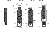
- FIGS. 1B-1D illustrate different stages of use of the tendon anchoring system.
- FIG. 1B illustrates the screw 107 coupled to the inner shaft 103 and being advanced through the outer shaft 109 and toward the sheath 111.
- the inner shaft 103 is rotated, as shown by arrow A, to cause the threads on the screw 107 to threadably engage with internal threads (not shown) formed within the sheath.
- Clockwise rotation of the inner shaft 103 continues until a distal-face of the handle 101 abuts against the proximal end 115 of the outer shaft 109, as shown in FIG. 1C .
- the threaded expander screw 107 is fully threaded into the sheath 111.
- the proximal end 115 can function as a hard-stop which indicates full advancement of the screw 107 into the sheath 111.
- the inner shaft 103 can be disengaged from the screw 107 and retracted from the outer shaft 109, as shown in FIG. 1D .
- the drive tip 105 on the inner shaft 103 includes threads formed thereon that mate with corresponding threads formed within the drive recess in the screw 107, as indicated by reference t.
- the drive tip 105 is fully threaded into the expander screw 107, further rotation of the inner shaft 103 relative to the expander screw 107 will be prevented.
- the threads t will function to prevent further rotation of the inner shaft 103 relative to the outer shaft 109.
- the inner shaft 103 would be free to rotate, without further distal movement, relative to the outer shaft 109. Such rotation could undesirably cause the expander screw 107 to rotate and advance further distally into the sheath 111.
- FIGS. 2A-2D illustrate another embodiment of the tendon anchoring assembly 200 having a sheath insert tool with an outer shaft 209 and an inner shaft 203 disposed therein and having a drive tip 205 configured to engage a drive recess in a threaded screw 207.
- the tip and the drive recess can be threaded for preventing further rotation of the inner shaft 203 relative to the expander screw 207 when the drive tip is fully threaded into the recess.
- the distal end of the inner shaft is configured to abut a proximal end of the sheath to thereby limit the insertion depth.
- the outer shaft 209 has an inner lumen with a diameter O 3 that is greater than a diameter S 3 of an inner lumen of the sheath 211, but that is less than an outer diameter S 4 of the sheath 211. This allows a distal end of the outer shaft 209 to mate to a proximal end 213 of the sheath 211 or at least abuts against it.
- the inner shaft 203 can have an outer diameter I 1 that is greater than a diameter S 3 of an inner lumen of the sheath 211 such that the distal end of the inner shaft 203 will abut a proximal end 215 of the sheath 211 to form a hard stop.
- distal movement of the inner shaft 203 through the outer shaft 209 will advance the expander screw 207 into the sheath 211, as shown in FIG. 2B .
- the expander screw 207 is fully threaded into the sheath 211, as shown in FIG. 2C , the distal end of the inner shaft 203 will abut the proximal end of the sheath 211 to prevent further advance of the inner shaft 203. Since the drive tip 205 on the inner shaft 203 is threaded into the recess in the expander screw 207, further rotation of the inner shaft 203 will be prevented.
- the inner shaft 203 can be rotated in a counter-clockwise direction to unthread the drive tip from the drive recess in the expander screw 207, thus allowing the inner shaft 203 to be removed from the outer shaft 209, as shown in FIG. 2D .
- FIGS. 1 and 2 generally describe a tendon anchoring assembly having a distal drive tip which engages a drive recess in the threaded expander screw.
- the number of turns of the drive tip into the threaded recess in the expander screw determines the tightness.
- the drive tip may become jammed into the drive recess in the expander screw as a result of overturning of the inner shaft relative to the expander screw.
- FIG 3 an alternative embodiment of the distal drive assembly is illustrated in FIG 3 .
- the stop feature shown in FIG. 3 can be utilized in connection with the tendon anchoring assemblies of FIGS. 1 and 2 .
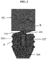
- FIG. 3 illustrates an embodiment of an inner shaft 301 and an expander screw 309 having a feature for limiting an insertion depth of a drive tip 305 on the inner shaft 301 into a drive recess 307 in the expander screw 309.
- the expander screw 309 includes a stop surface or wedge 311 formed one a proximal end thereof, and the inner shaft 301 includes a corresponding stop surface or wedge 303 formed on a distal end thereof.
- Each wedge 303, 311 has a vertical surface that is configured to carry a load and limit over-insertion of the drive tip 305 into the drive recess 307 in the expander screw 309.
- the wedges 303, 311 can be arranged in opposite directions such that the vertical surfaces are configured to abut one another to thereby prevent further rotation of the inner shaft 301 relative to the expander screw 309.
- the vertical surface on the end of each wedge 303, 311 has a height h that is less than a pitch p of the threads on the drive tip 305 and within the drive recess 307.
- Such a configuration will allow the wedge 303 on the inner shaft 301 to be spaced apart from the wedge 311 on the expander screw 309 by a distance that is greater than the height h of the vertical surface after one full rotation of the drive tip 305 relative to the drive recess 307.
- the wedges 303, 311 will not contact one another during a second rotation of the inner shaft 301 relative to the expander screw 309.
- the drive tip 305 will be threaded all the way into the threaded expander screw 309.
- the vertical surface of wedge 303 will strike the vertical surface of wedge 311. Once this occurs, the drive tip 305 is prevented from rotating relative to the drive recess 307, and instead the inner shaft 301 and the expander screw 309 rotate as a unit.
- the inner shaft can be counter-rotated to easily unthread the drive tip 305 from the drive recess 307.
- the drive tip can be a hex drive.
- FIG. 4 refers to a tendon anchoring procedure in which the drive tip is a hex drive and the rotation of the drive tip is limited by features at a proximal or a distal end of a handle assembly, an inserter tool having an inner and outer shaft, and/or a sheath.
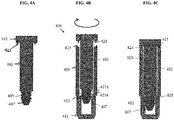
- FIGS. 4A-4C illustrates another embodiment of a tendon anchoring system that is similar to the system of FIGS. 2A-2D , and that generally includes an inner shaft 403, an outer shaft 408, an expander screw 407, and a sheath 411.
- the inner shaft 403 includes a distal drive tip 405 that engages a drive recess in the expander screw 407, as well as a handle 401 coupled to a proximal end thereof.
- the drive tip 405 is not threaded, but has a hexagonal or other non-circular shape that engages a complementary drive recess in the expander screw 407.
- the device has a clutch assembly formed between the handle 401 of the inner shaft 403 and the outer shaft 409 to limit rotation of the inner shaft 403 relative to the outer shaft 409.
- the distal facing surface of the handle 401 and the proximal facing surface of the outer shaft 409 each include surface features or clutches 421, 423 formed thereon.
- the clutches can have a variety of configurations, and can be in the form of teeth, protrusions, etc.
- the clutch 421 on the handle 401 will interlock with the clutch 423 on the proximal end of the outer shaft 409 of the sheath inserter tool 400 thereby preventing further rotation.
- 4B-4C illustrate the inner shaft 403 advancing the expander screw 407 into the sheath 411 and once fully threaded into the sheath, the clutches 421, 423 will abut and engage one another to prevent further rotation of the inner shaft 403 relative to the outer shaft 409.
- clutches 421, 423 can vary.
- a clutch can be positioned on a distal end 421a of the inner shaft 403, and a corresponding clutch can be positioned on a proximal end 423a of the sheath 411.
- the clutches can also have a variety of configurations.
- the clutches are in the form of teeth.
- the clutch engagement feature can be vertical stop surfaces, protrusions, detents, etc.
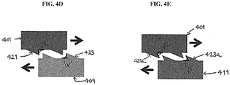
- FIG. 4D illustrates a tooth configuration for clutch 421 having an angle ⁇ and clutch 423 having an angle ⁇ '.
- the angles ⁇ , ⁇ ' in FIG. 4D are equal to 90 degrees.
- the clutches can be configured to have angles ⁇ , ⁇ ' that are less than 90 degrees, as shown in FIG. 4E .
- clutch 421a has an angle ⁇
- clutch 423a has an angle ⁇ '.
- Such a configuration can result in a mechanical interlock between the clutches, thereby preventing further rotation of the inner shaft and expander screw relative to the outer shaft and sheath once the expander screw is fully threaded into the sheath.
- FIGS. 5A-5H illustrate an another embodiment of a tendon anchoring assembly.
- the inner shaft 503 has a generally elongate configuration with a distal end 505 that is configured to mate to the expander screw 507.
- the distal end 505 can have a variety of configurations, but in generally it has a proximal drive portion 531 and a distal portion 533.
- the proximal drive portion 531 is configured to apply a driving force to the expander screw 507 to drive the expander screw into a sheath
- the distal portion 533 is configured to maintain alignment between the inner shaft and the expander screw while also functioning to cause the proximal drive portion 531 to become disengaged from the expander screw 507 with the screw is fully threaded into a sheath.
- the distal portion 533 can also form a press-fit engagement with the expander screw to hold the expander screw 507 onto the distal end of the inner shaft 503.
- the proximal drive portion 531 is in the form of a flat-head driver.
- the proximal drive portion can have any shape that is configured to engage and rotate a drive recess.
- the proximal drive portion can be square, hexagonal, etc.
- the illustrated flat-head proximal drive portion 531 is configured to engage a corresponding elongate slot 541 extending across a proximal end of the expander screw 507, as shown in FIGS. 5C and 5D .
- the distal portion 533 is in the form of a central pin that is configured to extend into an elongate bore 543 formed in the expander screw 507.
- the central pin is preferably freely rotatable within the elongate bore 543 such that rotation of the pin does not cause any corresponding rotation of the expander screw 507.
- the flat-head 531 has a height that is less than a height of the central pin 533 extending distally from it.
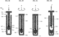
- FIGS. 5E-5H illustrate different stages of use of a tendon anchoring assembly 500, which includes the embodiments shown in FIGS. 5A-5D .
- the distal end 505 having a flat-head 531 and central pin 533 protruding distally from the flat-head can engage the screw 507.
- the central pin 533 of the distal end 505 can frictionally mate with a central drive socket 543 of the screw 507 and the flat-head 531 of the distal end 505 can extend into the slot 541.
- the distal end of the outer shaft 509 is mated to the proximal end 513 of the sheath 511. As shown in FIG.
- the first stage of the tendon anchoring procedure is to advance the threaded expander screw 507 into the sheath 511.
- inner shaft 503 is plunged in a distal direction F into a proximal end of the outer shaft 509 toward a distal-most end.
- the handle 501 will abut the proximal end of the outer shaft 509 when the expander screw 507 is fully threaded into the sheath 511. Further rotation of the inner shaft 503 will continue to rotate the expander screw 507 into the sheath 511.
- biceps tenodesis methods and devices disclosed herein can be used in a variety of surgical procedures to prevent trauma or damage to a tendon being attached to a bone via a bone hole.
- the present invention also has application in conventional joint repair surgeries.
- the devices disclosed herein can be designed to be disposed of after a single use, or they can be designed to be used multiple times. In either case, however, the device can be reconditioned for reuse after at least one use. Reconditioning can include any combination of the steps of disassembly of the device, followed by cleaning or replacement of particular pieces, and subsequent reassembly. In particular, the device can be disassembled, and any number of the particular pieces or parts of the device can be selectively replaced or removed in any combination. Upon cleaning and/or replacement of particular parts, the device can be reassembled for subsequent use either at a reconditioning facility, or by a surgical team immediately prior to a surgical procedure.
- reconditioning of a device can utilize a variety of techniques for disassembly, cleaning/replacement, and reassembly. Use of such techniques, and the resulting reconditioned device, are all within the scope of the present application.
- the invention described herein will be processed before surgery.
- a new or used instrument is obtained and if necessary cleaned.
- the instrument can then be sterilized.
- the instrument is placed in a closed and sealed container, such as a plastic or TYVEK bag.
- the container and instrument are then placed in a field of radiation that can penetrate the container, such as gamma radiation, x-rays, or high-energy electrons.
- the radiation kills bacteria on the instrument and in the container.
- the sterilized instrument can then be stored in the sterile container.
- the sealed container keeps the instrument sterile until it is opened in the medical facility.
- device is sterilized. This can be done by any number of ways known to those skilled in the art including beta or gamma radiation, ethylene oxide, steam.
Landscapes
- Health & Medical Sciences (AREA)
- Life Sciences & Earth Sciences (AREA)
- Surgery (AREA)
- Heart & Thoracic Surgery (AREA)
- Rheumatology (AREA)
- Engineering & Computer Science (AREA)
- Biomedical Technology (AREA)
- Public Health (AREA)
- Veterinary Medicine (AREA)
- Animal Behavior & Ethology (AREA)
- General Health & Medical Sciences (AREA)
- Medical Informatics (AREA)
- Nuclear Medicine, Radiotherapy & Molecular Imaging (AREA)
- Molecular Biology (AREA)
- Oral & Maxillofacial Surgery (AREA)
- Vascular Medicine (AREA)
- Transplantation (AREA)
- Cardiology (AREA)
- Rehabilitation Therapy (AREA)
- Orthopedic Medicine & Surgery (AREA)
- Surgical Instruments (AREA)
- Prostheses (AREA)
Applications Claiming Priority (1)
| Application Number | Priority Date | Filing Date | Title |
|---|---|---|---|
| US15/164,307 US10390936B2 (en) | 2016-05-25 | 2016-05-25 | Overdrive prevention for expandable anchor |
Publications (3)
| Publication Number | Publication Date |
|---|---|
| EP3248548A2 true EP3248548A2 (de) | 2017-11-29 |
| EP3248548A3 EP3248548A3 (de) | 2018-02-28 |
| EP3248548B1 EP3248548B1 (de) | 2022-12-21 |
Family
ID=58992662
Family Applications (1)
| Application Number | Title | Priority Date | Filing Date |
|---|---|---|---|
| EP17172946.0A Active EP3248548B1 (de) | 2016-05-25 | 2017-05-25 | Schnellgangprävention für spreizanker |
Country Status (5)
| Country | Link |
|---|---|
| US (2) | US10390936B2 (de) |
| EP (1) | EP3248548B1 (de) |
| JP (1) | JP7123529B2 (de) |
| CN (1) | CN107432757B (de) |
| AU (1) | AU2017203134B2 (de) |
Families Citing this family (2)
| Publication number | Priority date | Publication date | Assignee | Title |
|---|---|---|---|---|
| US10390936B2 (en) | 2016-05-25 | 2019-08-27 | Medos International Sarl | Overdrive prevention for expandable anchor |
| US10624734B2 (en) * | 2016-10-18 | 2020-04-21 | Arthrex, Inc. | Surgical assembly for tissue repair |
Family Cites Families (26)
| Publication number | Priority date | Publication date | Assignee | Title |
|---|---|---|---|---|
| US2604912A (en) * | 1949-02-04 | 1952-07-29 | Western Electric Co | Screw driver |
| US3943800A (en) | 1975-02-18 | 1976-03-16 | Chicago Pneumatic Tool Company | Portable screw driving tool having screw depth control feature |
| US5101698A (en) | 1990-05-24 | 1992-04-07 | Bernardo Paradiso | Screw head depth limiter |
| WO1994017961A1 (en) | 1993-02-10 | 1994-08-18 | Marvin Bassell | Fastener and driving tool |
| US5524512A (en) | 1994-03-11 | 1996-06-11 | Ryobi Motor Products Corp. | Drywall screwdriver depth adjustment |
| US5682800A (en) | 1996-03-05 | 1997-11-04 | Jore; Matthew B. | Clutch driver |
| BR9805340B1 (pt) * | 1998-12-14 | 2009-01-13 | inserto de expansço variÁvel para estabilizaÇço de coluna vertebral. | |
| AUPQ366099A0 (en) * | 1999-10-26 | 1999-11-18 | Queensland University Of Technology | Ortho paedic screw |
| AUPQ727500A0 (en) | 2000-05-03 | 2000-05-25 | Itw Australia Pty Ltd | A screw fastener |
| US6497166B1 (en) | 2000-11-07 | 2002-12-24 | Mark Fleckenstein | Screw setter tool |
| US7160109B2 (en) | 2001-09-17 | 2007-01-09 | Sulzer Dental Inc. | Torque limiting implant drive system |
| US7787934B2 (en) * | 2002-07-29 | 2010-08-31 | Medtronic, Inc. | Fiducial marker devices, tools, and methods |
| US20060079903A1 (en) | 2004-10-08 | 2006-04-13 | Wong David A | Minimally invasive pedicle screw and guide support |
| US20080289459A1 (en) | 2007-08-28 | 2008-11-27 | Yablon Bruce B | Screw Holding and Driving-Control Apparatus and Method |
| JP5698130B2 (ja) * | 2008-07-17 | 2015-04-08 | スミス アンド ネフュー インコーポレーテッドSmith & Nephew,Inc. | 手術用デバイス |
| EP2498686B1 (de) * | 2009-11-10 | 2024-01-10 | Smith & Nephew, Inc. | Vorrichtungen für gewebereparatur |
| WO2011153455A2 (en) | 2010-06-04 | 2011-12-08 | The University Of North Carolina At Chapel Hill | Screw holder-driver apparatuses, systems and methods |
| EP2598063A1 (de) | 2010-07-28 | 2013-06-05 | Synthes GmbH | System oder knochenfixation mit biologisch abbaubarer schraube mit radialen ausschnitten |
| US10980586B2 (en) | 2011-03-14 | 2021-04-20 | DePuy Synthes Products, Inc. | Driver device with anti-rotation feature |
| US9387025B2 (en) | 2012-04-04 | 2016-07-12 | Smith & Nephew, Inc. | Bone screw and self-retaining driver |
| US20150190130A1 (en) * | 2014-01-06 | 2015-07-09 | Groh Enterprises | Device and method for anchoring soft tissue to bone |
| WO2016057514A1 (en) | 2014-10-06 | 2016-04-14 | Implantable Design, Llc | Distraction plate system |
| US10729419B2 (en) * | 2014-10-23 | 2020-08-04 | Medos International Sarl | Biceps tenodesis implants and delivery tools |
| US10034742B2 (en) | 2014-10-23 | 2018-07-31 | Medos International Sarl | Biceps tenodesis implants and delivery tools |
| US9693856B2 (en) * | 2015-04-22 | 2017-07-04 | DePuy Synthes Products, LLC | Biceps repair device |
| US10390936B2 (en) | 2016-05-25 | 2019-08-27 | Medos International Sarl | Overdrive prevention for expandable anchor |
-
2016
- 2016-05-25 US US15/164,307 patent/US10390936B2/en active Active
-
2017
- 2017-05-11 AU AU2017203134A patent/AU2017203134B2/en active Active
- 2017-05-24 JP JP2017102392A patent/JP7123529B2/ja active Active
- 2017-05-25 CN CN201710378563.8A patent/CN107432757B/zh active Active
- 2017-05-25 EP EP17172946.0A patent/EP3248548B1/de active Active
-
2019
- 2019-08-21 US US16/546,884 patent/US11666431B2/en active Active
Non-Patent Citations (1)
| Title |
|---|
| None |
Also Published As
| Publication number | Publication date |
|---|---|
| CN107432757A (zh) | 2017-12-05 |
| EP3248548A3 (de) | 2018-02-28 |
| US20170340435A1 (en) | 2017-11-30 |
| EP3248548B1 (de) | 2022-12-21 |
| AU2017203134B2 (en) | 2022-05-26 |
| JP2017209497A (ja) | 2017-11-30 |
| CN107432757B (zh) | 2021-09-03 |
| AU2017203134A1 (en) | 2017-12-14 |
| JP7123529B2 (ja) | 2022-08-23 |
| US20190374331A1 (en) | 2019-12-12 |
| US10390936B2 (en) | 2019-08-27 |
| US11666431B2 (en) | 2023-06-06 |
Similar Documents
| Publication | Publication Date | Title |
|---|---|---|
| US11793624B2 (en) | Tenodesis implants and tools | |
| US11284877B2 (en) | Biceps tenodesis implants and delivery tools | |
| US11576769B2 (en) | Method for anchoring biceps tenodesis | |
| US10869751B2 (en) | Biceps tenodesis implants and delivery tools | |
| US11065104B2 (en) | Tenodesis anchoring systems and tools | |
| AU2017216552B2 (en) | Bone graft fixation systems and methods | |
| US11666431B2 (en) | Overdrive prevention for expandable anchor |
Legal Events
| Date | Code | Title | Description |
|---|---|---|---|
| PUAI | Public reference made under article 153(3) epc to a published international application that has entered the european phase |
Free format text: ORIGINAL CODE: 0009012 |
|
| STAA | Information on the status of an ep patent application or granted ep patent |
Free format text: STATUS: THE APPLICATION HAS BEEN PUBLISHED |
|
| AK | Designated contracting states |
Kind code of ref document: A2 Designated state(s): AL AT BE BG CH CY CZ DE DK EE ES FI FR GB GR HR HU IE IS IT LI LT LU LV MC MK MT NL NO PL PT RO RS SE SI SK SM TR |
|
| AX | Request for extension of the european patent |
Extension state: BA ME |
|
| PUAL | Search report despatched |
Free format text: ORIGINAL CODE: 0009013 |
|
| AK | Designated contracting states |
Kind code of ref document: A3 Designated state(s): AL AT BE BG CH CY CZ DE DK EE ES FI FR GB GR HR HU IE IS IT LI LT LU LV MC MK MT NL NO PL PT RO RS SE SI SK SM TR |
|
| AX | Request for extension of the european patent |
Extension state: BA ME |
|
| RIC1 | Information provided on ipc code assigned before grant |
Ipc: A61B 90/00 20160101ALN20180122BHEP Ipc: A61F 2/08 20060101ALN20180122BHEP Ipc: A61B 17/04 20060101AFI20180122BHEP |
|
| RAP1 | Party data changed (applicant data changed or rights of an application transferred) |
Owner name: MEDOS INTERNATIONAL SARL |
|
| STAA | Information on the status of an ep patent application or granted ep patent |
Free format text: STATUS: REQUEST FOR EXAMINATION WAS MADE |
|
| 17P | Request for examination filed |
Effective date: 20180828 |
|
| RBV | Designated contracting states (corrected) |
Designated state(s): AL AT BE BG CH CY CZ DE DK EE ES FI FR GB GR HR HU IE IS IT LI LT LU LV MC MK MT NL NO PL PT RO RS SE SI SK SM TR |
|
| STAA | Information on the status of an ep patent application or granted ep patent |
Free format text: STATUS: EXAMINATION IS IN PROGRESS |
|
| 17Q | First examination report despatched |
Effective date: 20190424 |
|
| GRAP | Despatch of communication of intention to grant a patent |
Free format text: ORIGINAL CODE: EPIDOSNIGR1 |
|
| STAA | Information on the status of an ep patent application or granted ep patent |
Free format text: STATUS: GRANT OF PATENT IS INTENDED |
|
| RIC1 | Information provided on ipc code assigned before grant |
Ipc: A61B 90/00 20160101ALN20220613BHEP Ipc: A61F 2/08 20060101ALN20220613BHEP Ipc: A61B 17/04 20060101AFI20220613BHEP |
|
| INTG | Intention to grant announced |
Effective date: 20220705 |
|
| GRAJ | Information related to disapproval of communication of intention to grant by the applicant or resumption of examination proceedings by the epo deleted |
Free format text: ORIGINAL CODE: EPIDOSDIGR1 |
|
| STAA | Information on the status of an ep patent application or granted ep patent |
Free format text: STATUS: EXAMINATION IS IN PROGRESS |
|
| GRAP | Despatch of communication of intention to grant a patent |
Free format text: ORIGINAL CODE: EPIDOSNIGR1 |
|
| STAA | Information on the status of an ep patent application or granted ep patent |
Free format text: STATUS: GRANT OF PATENT IS INTENDED |
|
| INTC | Intention to grant announced (deleted) | ||
| RIC1 | Information provided on ipc code assigned before grant |
Ipc: A61B 90/00 20160101ALN20220901BHEP Ipc: A61F 2/08 20060101ALN20220901BHEP Ipc: A61B 17/04 20060101AFI20220901BHEP |
|
| INTG | Intention to grant announced |
Effective date: 20220922 |
|
| GRAS | Grant fee paid |
Free format text: ORIGINAL CODE: EPIDOSNIGR3 |
|
| GRAA | (expected) grant |
Free format text: ORIGINAL CODE: 0009210 |
|
| STAA | Information on the status of an ep patent application or granted ep patent |
Free format text: STATUS: THE PATENT HAS BEEN GRANTED |
|
| AK | Designated contracting states |
Kind code of ref document: B1 Designated state(s): AL AT BE BG CH CY CZ DE DK EE ES FI FR GB GR HR HU IE IS IT LI LT LU LV MC MK MT NL NO PL PT RO RS SE SI SK SM TR |
|
| REG | Reference to a national code |
Ref country code: GB Ref legal event code: FG4D |
|
| REG | Reference to a national code |
Ref country code: CH Ref legal event code: EP |
|
| REG | Reference to a national code |
Ref country code: DE Ref legal event code: R096 Ref document number: 602017064733 Country of ref document: DE |
|
| REG | Reference to a national code |
Ref country code: AT Ref legal event code: REF Ref document number: 1538566 Country of ref document: AT Kind code of ref document: T Effective date: 20230115 |
|
| REG | Reference to a national code |
Ref country code: IE Ref legal event code: FG4D |
|
| REG | Reference to a national code |
Ref country code: NL Ref legal event code: FP |
|
| REG | Reference to a national code |
Ref country code: FR Ref legal event code: PLFP Year of fee payment: 7 Ref country code: LT Ref legal event code: MG9D |
|
| PG25 | Lapsed in a contracting state [announced via postgrant information from national office to epo] |
Ref country code: SE Free format text: LAPSE BECAUSE OF FAILURE TO SUBMIT A TRANSLATION OF THE DESCRIPTION OR TO PAY THE FEE WITHIN THE PRESCRIBED TIME-LIMIT Effective date: 20221221 Ref country code: NO Free format text: LAPSE BECAUSE OF FAILURE TO SUBMIT A TRANSLATION OF THE DESCRIPTION OR TO PAY THE FEE WITHIN THE PRESCRIBED TIME-LIMIT Effective date: 20230321 Ref country code: LT Free format text: LAPSE BECAUSE OF FAILURE TO SUBMIT A TRANSLATION OF THE DESCRIPTION OR TO PAY THE FEE WITHIN THE PRESCRIBED TIME-LIMIT Effective date: 20221221 Ref country code: FI Free format text: LAPSE BECAUSE OF FAILURE TO SUBMIT A TRANSLATION OF THE DESCRIPTION OR TO PAY THE FEE WITHIN THE PRESCRIBED TIME-LIMIT Effective date: 20221221 |
|
| REG | Reference to a national code |
Ref country code: AT Ref legal event code: MK05 Ref document number: 1538566 Country of ref document: AT Kind code of ref document: T Effective date: 20221221 |
|
| PG25 | Lapsed in a contracting state [announced via postgrant information from national office to epo] |
Ref country code: RS Free format text: LAPSE BECAUSE OF FAILURE TO SUBMIT A TRANSLATION OF THE DESCRIPTION OR TO PAY THE FEE WITHIN THE PRESCRIBED TIME-LIMIT Effective date: 20221221 Ref country code: LV Free format text: LAPSE BECAUSE OF FAILURE TO SUBMIT A TRANSLATION OF THE DESCRIPTION OR TO PAY THE FEE WITHIN THE PRESCRIBED TIME-LIMIT Effective date: 20221221 Ref country code: HR Free format text: LAPSE BECAUSE OF FAILURE TO SUBMIT A TRANSLATION OF THE DESCRIPTION OR TO PAY THE FEE WITHIN THE PRESCRIBED TIME-LIMIT Effective date: 20221221 Ref country code: GR Free format text: LAPSE BECAUSE OF FAILURE TO SUBMIT A TRANSLATION OF THE DESCRIPTION OR TO PAY THE FEE WITHIN THE PRESCRIBED TIME-LIMIT Effective date: 20230322 |
|
| PG25 | Lapsed in a contracting state [announced via postgrant information from national office to epo] |
Ref country code: SM Free format text: LAPSE BECAUSE OF FAILURE TO SUBMIT A TRANSLATION OF THE DESCRIPTION OR TO PAY THE FEE WITHIN THE PRESCRIBED TIME-LIMIT Effective date: 20221221 Ref country code: RO Free format text: LAPSE BECAUSE OF FAILURE TO SUBMIT A TRANSLATION OF THE DESCRIPTION OR TO PAY THE FEE WITHIN THE PRESCRIBED TIME-LIMIT Effective date: 20221221 Ref country code: PT Free format text: LAPSE BECAUSE OF FAILURE TO SUBMIT A TRANSLATION OF THE DESCRIPTION OR TO PAY THE FEE WITHIN THE PRESCRIBED TIME-LIMIT Effective date: 20230421 Ref country code: ES Free format text: LAPSE BECAUSE OF FAILURE TO SUBMIT A TRANSLATION OF THE DESCRIPTION OR TO PAY THE FEE WITHIN THE PRESCRIBED TIME-LIMIT Effective date: 20221221 Ref country code: EE Free format text: LAPSE BECAUSE OF FAILURE TO SUBMIT A TRANSLATION OF THE DESCRIPTION OR TO PAY THE FEE WITHIN THE PRESCRIBED TIME-LIMIT Effective date: 20221221 Ref country code: CZ Free format text: LAPSE BECAUSE OF FAILURE TO SUBMIT A TRANSLATION OF THE DESCRIPTION OR TO PAY THE FEE WITHIN THE PRESCRIBED TIME-LIMIT Effective date: 20221221 Ref country code: AT Free format text: LAPSE BECAUSE OF FAILURE TO SUBMIT A TRANSLATION OF THE DESCRIPTION OR TO PAY THE FEE WITHIN THE PRESCRIBED TIME-LIMIT Effective date: 20221221 |
|
| PG25 | Lapsed in a contracting state [announced via postgrant information from national office to epo] |
Ref country code: SK Free format text: LAPSE BECAUSE OF FAILURE TO SUBMIT A TRANSLATION OF THE DESCRIPTION OR TO PAY THE FEE WITHIN THE PRESCRIBED TIME-LIMIT Effective date: 20221221 Ref country code: PL Free format text: LAPSE BECAUSE OF FAILURE TO SUBMIT A TRANSLATION OF THE DESCRIPTION OR TO PAY THE FEE WITHIN THE PRESCRIBED TIME-LIMIT Effective date: 20221221 Ref country code: IS Free format text: LAPSE BECAUSE OF FAILURE TO SUBMIT A TRANSLATION OF THE DESCRIPTION OR TO PAY THE FEE WITHIN THE PRESCRIBED TIME-LIMIT Effective date: 20230421 Ref country code: AL Free format text: LAPSE BECAUSE OF FAILURE TO SUBMIT A TRANSLATION OF THE DESCRIPTION OR TO PAY THE FEE WITHIN THE PRESCRIBED TIME-LIMIT Effective date: 20221221 |
|
| REG | Reference to a national code |
Ref country code: DE Ref legal event code: R097 Ref document number: 602017064733 Country of ref document: DE |
|
| PLBE | No opposition filed within time limit |
Free format text: ORIGINAL CODE: 0009261 |
|
| STAA | Information on the status of an ep patent application or granted ep patent |
Free format text: STATUS: NO OPPOSITION FILED WITHIN TIME LIMIT |
|
| PG25 | Lapsed in a contracting state [announced via postgrant information from national office to epo] |
Ref country code: DK Free format text: LAPSE BECAUSE OF FAILURE TO SUBMIT A TRANSLATION OF THE DESCRIPTION OR TO PAY THE FEE WITHIN THE PRESCRIBED TIME-LIMIT Effective date: 20221221 |
|
| 26N | No opposition filed |
Effective date: 20230922 |
|
| PG25 | Lapsed in a contracting state [announced via postgrant information from national office to epo] |
Ref country code: MC Free format text: LAPSE BECAUSE OF FAILURE TO SUBMIT A TRANSLATION OF THE DESCRIPTION OR TO PAY THE FEE WITHIN THE PRESCRIBED TIME-LIMIT Effective date: 20221221 |
|
| REG | Reference to a national code |
Ref country code: BE Ref legal event code: MM Effective date: 20230531 |
|
| PG25 | Lapsed in a contracting state [announced via postgrant information from national office to epo] |
Ref country code: SI Free format text: LAPSE BECAUSE OF FAILURE TO SUBMIT A TRANSLATION OF THE DESCRIPTION OR TO PAY THE FEE WITHIN THE PRESCRIBED TIME-LIMIT Effective date: 20221221 Ref country code: MC Free format text: LAPSE BECAUSE OF FAILURE TO SUBMIT A TRANSLATION OF THE DESCRIPTION OR TO PAY THE FEE WITHIN THE PRESCRIBED TIME-LIMIT Effective date: 20221221 Ref country code: LU Free format text: LAPSE BECAUSE OF NON-PAYMENT OF DUE FEES Effective date: 20230525 |
|
| REG | Reference to a national code |
Ref country code: IE Ref legal event code: MM4A |
|
| PG25 | Lapsed in a contracting state [announced via postgrant information from national office to epo] |
Ref country code: IE Free format text: LAPSE BECAUSE OF NON-PAYMENT OF DUE FEES Effective date: 20230525 |
|
| PG25 | Lapsed in a contracting state [announced via postgrant information from national office to epo] |
Ref country code: IE Free format text: LAPSE BECAUSE OF NON-PAYMENT OF DUE FEES Effective date: 20230525 |
|
| PG25 | Lapsed in a contracting state [announced via postgrant information from national office to epo] |
Ref country code: BE Free format text: LAPSE BECAUSE OF NON-PAYMENT OF DUE FEES Effective date: 20230531 |
|
| PG25 | Lapsed in a contracting state [announced via postgrant information from national office to epo] |
Ref country code: BG Free format text: LAPSE BECAUSE OF FAILURE TO SUBMIT A TRANSLATION OF THE DESCRIPTION OR TO PAY THE FEE WITHIN THE PRESCRIBED TIME-LIMIT Effective date: 20221221 |
|
| PG25 | Lapsed in a contracting state [announced via postgrant information from national office to epo] |
Ref country code: BG Free format text: LAPSE BECAUSE OF FAILURE TO SUBMIT A TRANSLATION OF THE DESCRIPTION OR TO PAY THE FEE WITHIN THE PRESCRIBED TIME-LIMIT Effective date: 20221221 |
|
| PGFP | Annual fee paid to national office [announced via postgrant information from national office to epo] |
Ref country code: NL Payment date: 20250409 Year of fee payment: 9 |
|
| PGFP | Annual fee paid to national office [announced via postgrant information from national office to epo] |
Ref country code: DE Payment date: 20250402 Year of fee payment: 9 |
|
| PGFP | Annual fee paid to national office [announced via postgrant information from national office to epo] |
Ref country code: IT Payment date: 20250422 Year of fee payment: 9 |
|
| PGFP | Annual fee paid to national office [announced via postgrant information from national office to epo] |
Ref country code: FR Payment date: 20250401 Year of fee payment: 9 |
|
| PGFP | Annual fee paid to national office [announced via postgrant information from national office to epo] |
Ref country code: CH Payment date: 20250601 Year of fee payment: 9 |
|
| PG25 | Lapsed in a contracting state [announced via postgrant information from national office to epo] |
Ref country code: CY Free format text: LAPSE BECAUSE OF FAILURE TO SUBMIT A TRANSLATION OF THE DESCRIPTION OR TO PAY THE FEE WITHIN THE PRESCRIBED TIME-LIMIT; INVALID AB INITIO Effective date: 20170525 |
|
| PG25 | Lapsed in a contracting state [announced via postgrant information from national office to epo] |
Ref country code: HU Free format text: LAPSE BECAUSE OF FAILURE TO SUBMIT A TRANSLATION OF THE DESCRIPTION OR TO PAY THE FEE WITHIN THE PRESCRIBED TIME-LIMIT; INVALID AB INITIO Effective date: 20170525 |
|
| PG25 | Lapsed in a contracting state [announced via postgrant information from national office to epo] |
Ref country code: TR Free format text: LAPSE BECAUSE OF FAILURE TO SUBMIT A TRANSLATION OF THE DESCRIPTION OR TO PAY THE FEE WITHIN THE PRESCRIBED TIME-LIMIT Effective date: 20221221 |
|
| PGFP | Annual fee paid to national office [announced via postgrant information from national office to epo] |
Ref country code: GB Payment date: 20260324 Year of fee payment: 10 |