EP3248503B1 - Beschlag für möbel oder dergleichen - Google Patents
Beschlag für möbel oder dergleichen Download PDFInfo
- Publication number
- EP3248503B1 EP3248503B1 EP17000907.0A EP17000907A EP3248503B1 EP 3248503 B1 EP3248503 B1 EP 3248503B1 EP 17000907 A EP17000907 A EP 17000907A EP 3248503 B1 EP3248503 B1 EP 3248503B1
- Authority
- EP
- European Patent Office
- Prior art keywords
- fitting according
- sensor
- damping device
- weight detection
- detection device
- Prior art date
- Legal status (The legal status is an assumption and is not a legal conclusion. Google has not performed a legal analysis and makes no representation as to the accuracy of the status listed.)
- Active
Links
Images


Classifications
-
- A—HUMAN NECESSITIES
- A47—FURNITURE; DOMESTIC ARTICLES OR APPLIANCES; COFFEE MILLS; SPICE MILLS; SUCTION CLEANERS IN GENERAL
- A47B—TABLES; DESKS; OFFICE FURNITURE; CABINETS; DRAWERS; GENERAL DETAILS OF FURNITURE
- A47B77/00—Kitchen cabinets
- A47B77/04—Provision for particular uses of compartments or other parts ; Compartments moving up and down, revolving parts
- A47B77/10—Provision for particular uses of compartments or other parts ; Compartments moving up and down, revolving parts with members movable outwards to a position of use, e.g. tables, ironing boards
-
- A—HUMAN NECESSITIES
- A47—FURNITURE; DOMESTIC ARTICLES OR APPLIANCES; COFFEE MILLS; SPICE MILLS; SUCTION CLEANERS IN GENERAL
- A47B—TABLES; DESKS; OFFICE FURNITURE; CABINETS; DRAWERS; GENERAL DETAILS OF FURNITURE
- A47B88/00—Drawers for tables, cabinets or like furniture; Guides for drawers
-
- A—HUMAN NECESSITIES
- A47—FURNITURE; DOMESTIC ARTICLES OR APPLIANCES; COFFEE MILLS; SPICE MILLS; SUCTION CLEANERS IN GENERAL
- A47B—TABLES; DESKS; OFFICE FURNITURE; CABINETS; DRAWERS; GENERAL DETAILS OF FURNITURE
- A47B2210/00—General construction of drawers, guides and guide devices
- A47B2210/0091—Drawer movement damping
Definitions
- the invention relates to a fitting for furniture and the like having a body furnishings, especially for kitchen cabinet furniture, with a supportable on a carcass, translationally movable and / or pivoting pull-out frame with at least one receptacle for supporting at least one object and with a damping device, said the movement of the extension frame can be braked by the damping device before reaching an end position located in the body, and with a device for determining a loading state value of the extension frame (103), whereby the braking behavior of the damping device can be changed automatically depending on the determined loading state value of the extension frame (103)
- a fitting for furniture, in particular a pull-out frame for a kitchen cabinet furniture, with a damping system is for example from the DE 10 2008 029 775 A1 known.
- a damping device is provided for braking a movement of a relative to a body movable furniture part with a damping device, which is to be guided in a sliding space, wherein the displacement of the piston in the sliding space generates a damping.
- a spring-back moment should be avoided in order to prevent a movement counter to the closing movement when a certain overpressure is generated during the closing movement.
- the piston chamber is designed to be open on the back, wherein the displaced fluid in the sliding chamber must be supplied to a larger volume. This may be possible avoid an unwanted spring-back moment.
- certain and thus permanently pre-installed damping properties are to be provided, which are designed for a nominal payload. This can have a detrimental effect in the everyday operation of such a fitting.
- U1 is a fitting for furniture o.
- This fitting is provided with a receptacle for supporting at least one object, wherein the movement of the extension frame can be braked by a damping device before reaching an end position located in the body.
- an accelerometer for this purpose, motion profiles which are assigned to a negative or positive acceleration of the movable furniture part can be stored in a data memory.
- From the AT 414 004 B is a piece of furniture with at least one movable furniture part and a drive for moving the movable furniture part known.
- a control and regulating device for controlling or regulating the drive unit are provided and a sensor device is provided, which serves to detect movements of an object located outside of the furniture, whose signals can be fed to at least the control and regulating device.
- the control and regulating device has an operating mode for driving the movable furniture part, in which the movable furniture part follows at least one movement component of the object detected by the sensor device.
- the operating mode provides that the movable furniture part, for example, a drawer is guided in accordance with the movement of the hand at a certain distance to this. It is also possible that the movable furniture part also rests directly on the hand and follows the movement of the hand. The detection of the loading condition is not provided.
- U1 is a device for influencing the movement of furniture parts and furniture movable to each other known with a drive unit, by means of which via a control unit for controlling movement of a first furniture part this is driven relative to a second furniture part movable.
- the control unit is designed such that the control unit works after commissioning according to a program for the movement control of the first furniture part, wherein selection means are provided with which an alternative election program for the movement control of the first furniture part can be activated instead of the control program.
- selection means are provided with which an alternative election program for the movement control of the first furniture part can be activated instead of the control program.
- Another generic fitting is from the US 2014/0135994 A1 known.
- the fitting of the type mentioned above is characterized in that the fitting has a control device for actuating the damping device and the communication between the control device and the device for determining a load state value over a radio link, via an infrared link, via ultrasound and / or via electrical cables.
- a weight detection device is preferably provided, which together with a control device acts, over which the braking force can be adjusted.
- the weight detection device may include a weight change sensor to detect, for example, directly after the loading of the extension frame in its open position, the changed weight ratios, and then adjust the braking force of the damping device accordingly already in the extended state.
- the control of the damping device via a control device.
- the transmission of measurement data can take place in various ways, by cable, by radio, via an infrared link, via ultrasound or similar measured value transmission links.
- Sensors can be used to determine the load condition value.
- deformation sensors, deformation change sensors, position sensors, position change sensors, speed sensors, speed change sensors, acceleration sensors and / or acceleration change sensors are suitable as technical components in order to determine the load state value of the extension frame.
- Braking devices which may be used in the braking device are, for example, mechanical, electrical, fluid, magnetic or electrorheological dampers. These friction brakes, rotary brakes, induction or eddy current brakes, hysteresis brakes, flow brakes, fluid brakes or similar brakes can be used.
- a weight sensor or as a weight change sensor can be arranged, for example, a load cell with strain gauges in or on the body of a piece of furniture. If, for example, a telescopic extension is used, strain gauges can be arranged underneath the guide rail of the Telescopic extension be set.
- a deformation sensor offers a piezoelectric sensor. The amplitude and polarity can be an indication of the weight or the weight change on the extension frame.
- a speed sensor or a speed change sensor may be implemented as a generator. The change in speed over a defined distance with a defined braking force is an indication of the weight or the change in weight of the extension frame.
- Sensor, brake device and control can be performed in a common component.
- an eddy current brake is also suitable.
- a position sensor or a position change sensor may be configured as a tilt sensor.
- the extension frame lowers to one side, for example by a guide rail of a telescopic extension is elastically supported on one side, for example via a spring.
- the inclination is an indication of the weight or weight change on the extension frame.
- an acceleration sensor or an acceleration change sensor may be implemented as a microelectromechanical system (MEMS). This sensor can be arranged in or on the movable part of the fitting.
- MEMS microelectromechanical system
- a piece of furniture is numbered with a body 101, on whose side walls 102 guide rails 2 of a slide-out frame 103 are fastened, in which telescopic rails 9 of the slide-out frame 103 are guided.
- the telescopic rails 9 carry more detailed conditions or a floor for supporting objects to be stored.
- the telescopic rails 9 are connected to a front furniture front 104 with a control handle 105.
- the body 101 rests on supports 106.
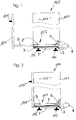
- Fig. 1 the drawer 103 is shown in its extended position
- this embodiment in Fig. 2 is shown in the closed state, in which the extension frame 103 is in the Sch strictd ein.
- weight sensors 3 are arranged as a device for determining a loading state of the extension frame 103 in the form of load cells. By means of these weight sensors 3, the loading of the extension frame 103 can be determined become.
- the determined measured values are fed to a control unit 4 and processed there.
- the damping device 5 is in the embodiment of the Fig. 1 and 2 realized as a fluid brake or compression damper with a non-visible variable flow channel.
- variable flow channel can eg be darg Horpic Rails 9 during a slide movement of the extension frame 103.
- a corresponding cross-section can be adjusted via the control unit 4 controlled in the flow channel.
- a reduction in the cross section of this flow channel ensures a stronger, an increase in the cross section for a weaker delay of the telescopic rails 9 during a slide movement of the extension frame 103.
- an automatic collection device can be provided. The load of the extension rack 103 can be determined directly in the course of the insertion movement and transmitted via the control unit 4 to the delay element 5 and the damping device 5.
- the furniture 100 is equipped with a pull-out frame 103 with guide rails 2 and telescopic rails 9, wherein the guide rail 102 in the rear region at 7.1 rotatory, that is supported on rollers.
- a weight change sensor 7 is provided as a load state value detection device. The load change is transmitted to the control unit 4 via this weight change sensor 7.
- the control unit evaluates the data and controls the deceleration or braking member (damping device) according to the required delay due to the determined load condition values. It is also possible to shift the weight change sensor 7 in the rear area and move the position 7.1 forward. As a result, the weight would be determined by train and not by pressure on the sensor.
- Fig. 4 is another alternative embodiment of a piece of furniture 100 with a variable electric rotary brake as a damping device 5 is formed.
- the rotation brake can be designed as hysteresis brake (not speed-dependent) or as eddy-current brake (speed-dependent).
- the damping device 5 has a in a rotational movement during the insertion movement displaceable friction wheel 10 is.
- the damping device 5 and the rotation brake act as a generator, wherein the generated voltage is determined by the control unit 4.
- the contact voltage is an indicator of the speed of movement of the movably mounted telescopic slide 9.
- variable load resistor 11 is adjusted. The changed load influences the required torque at the generator shaft.
- both the load state can be determined indirectly and used for the deceleration or deceleration, but also an excessive speed, which is performed by the operator when moving the excerpt 103.
- Fig. 5 shows a side view of a further alternative embodiment with in the rear area again on rollers supported at 7.1 guide rails 2 and a spaced therefrom arranged spring element 13, wherein the guide rail 2, an angle sensor 14 is associated.
- a control unit 4 are provided and two controllable fluid damper 15 as a damping device, so that hydrodynamic components and an electrorheological fluid (ERF) find use.
- ERP electrorheological fluid
- Fig. 6 is the embodiment after Fig. 5 shown in the loaded state by the black weight, whereby the force Kg acts in a vertical direction on the telescopic rail 9 and the local support 13.
- the spring element 13 is compressed by the weight of the load or the object to be dropped. Due to the elastic support of the guide rail 2, this lowers down (front), whereby the angle sensor 14 measures an angle change relative to the horizontal.
- the size of the angle change is a direct measure of the load.
- the determined angle change is evaluated by the control unit 4.
- the damper device fluid damper 15
- the damper device is appropriately adjusted to adjust the damping during the transfer of the extension rack 103 to the shift end position.
- the transmitted angle change can thereby be stored at least in the short term, based on a displacement caused by the closing movement To compensate for the fulcrum of the one-sided rotatably mounted guide rail 2.
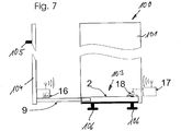
- a further embodiment of a fitting according to the invention is shown with a guide rail 2 fixed to the cabinet floor and in movably mounted telescopic rails 9.
- an acceleration sensor 16 is shown with at least one sensitive direction of acceleration.
- the acceleration sensor 16 is connected to the movably mounted telescopic rail 9 and transmits the recorded sensor signals wirelessly to the receiving device 17.
- the received signals are processed and set the adjustable friction brake 18 as a damping device according to the required delay value to be set.
Landscapes
- Vibration Prevention Devices (AREA)
Description
- Die Erfindung bezieht sich auf einen Beschlag für Möbel und dergleichen einen Korpus aufweisende Einrichtungsgegenstände, insbesondere für Küchenschrankmöbel, mit einem an einem Korpus abstützbaren, translatorisch bewegbaren und/oder schwenkbeweglichen Auszuggestell mit zumindest einer Aufnahme zur Abstützung von zumindest einem Gegenstand und mit einer Dämpfungsvorrichtung, wobei die Bewegung des Auszuggestells vor Erreichen einer in dem Korpus gelegenen Endstellung durch die Dämpfungsvorrichtung abbremsbar ist, und mit einer Vorrichtung zur Ermittlung eines Beladungszustandswertes des Auszuggestells (103), wobei das Abbremsverhalten der Dämpfungsvorrichtung in Abhängigkeit des ermittelten Beladungszustandswertes des Auszuggestells (103) selbsttätig veränderbar ist
- Ein Beschlag für Möbel, insbesondere ein Auszuggestell für ein Küchenschrankmöbel, mit einem Dämpfungssystem ist beispielsweise aus der
DE 10 2008 029 775 A1 bekannt. Bei diesem Möbelbeschlag ist zum Abbremsen einer Bewegung eines relativ zu einem Korpus bewegbaren Möbelteils eine Dämpfungsvorrichtung vorgesehen mit einem Kolben, der in einem Verschieberaum zu führen ist, wobei das Verschieben des Kolbens im Verschieberaum eine Dämpfung erzeugt. Dabei soll beim Abbremsvorgang ein rückfederndes Moment vermieden werden, um eine der Schließbewegung gegengerichtete Bewegung bei Erzeugung eines bestimmten Überdrucks während der Schließbewegung zu verhindern. Dazu ist vorgesehen, dass der Kolbenraum rückseitig offen ausgebildet ist, wobei das verdrängte Fluid im Schieberaum einem größeren Volumen zugeführt werden muss. Damit lässt sich möglicherweise ein unerwünschtes rückfederndes Moment vermeiden. Gleichwohl sind bestimmte und damit fest vorinstallierte Dämpfungseigenschaften vorzusehen, die auf eine nominelle Zuladung ausgelegt sind. Dies kann sich im Alltagsbetrieb eines derartigen Beschlages nachteilig auswirken. - Aus der
DE 20 2011 100 573 U1 ist ein Beschlag für Möbel o. dgl. einen Korpus aufweisende Einrichtungsgegenstände bekannt mit einem am Korpus abstützbaren, translatorisch bewegbaren und/oder schwenkbeweglichen Auszuggestell. Dieser Beschlag ist mit einer Aufnahme zur Abstützung von zumindest einem Gegenstand versehen, wobei die Bewegung des Auszuggestells vor Erreichen einer in dem Korpus gelegenen Endstellung durch eine Dämpfungsvorrichtung abbremsbar ist. Dabei ist es möglich, einen Beschleunigungsaufnehmer einzusetzen. In einem Datenspeicher können hierzu Bewegungsprofile abgespeichert sein, die einer negativen oder positiven Beschleunigung des bewegbaren Möbelteils zugeordnet sind. - Aus der
AT 414 004 B - Aus der
DE 21 2007 000 006 U1 ist eine Vorrichtung für die Bewegungsbeeinflussung von zueinander bewegbaren Möbelteilen und Möbeln bekannt mit einer Antriebseinheit, mittels der über eine Kontrolleinheit zur Bewegungskontrolle eines ersten Möbelteils dieses relativ zu einem zweiten Möbelteil angetrieben bewegbar ist. Dabei ist die Kontrolleinheit derart ausgebildet, dass die Kontrolleinheit nach einer Inbetriebnahme gemäß einem Programm für die Bewegungskontrolle des ersten Möbelteils arbeitet, wobei Auswahlmittel vorhanden sind, mit denen an Stelle des Kontrollprogramms ein alternatives Wahlprogramm für die Bewegungskontrolle des ersten Möbelteils aktivierbar ist. Damit ist jedoch nicht die Erkennung eines Beladungszustandes möglich. Ein weiterer gattungsgemäßer Beschlag ist aus derUS 2014/0135994 A1 bekannt. - Es ist Aufgabe der vorliegenden Erfindung, einen Beschlag für Möbel o. dgl. einen Korpus aufweisenden Einrichtungsgegenstände zu schaffen, bei dem sich das translatorisch bewegbare und/oder schwenkbewegliche Auszuggestell individueller dem Alltagsbetrieb anpassen lässt.
- Zur Lösung dieser Aufgabe zeichnet sich der Beschlag der eingangs genannten Art dadurch aus, dass der Beschlag eine Steuerungsvorrichtung zur Betätigung der Dämpfungsvorrichtung aufweist und die Kommunikation zwischen der Steuerungsvorrichtung und der Vorrichtung zur Ermittlung eines Beladungszustandswertes über eine Funktstrecke, über eine Infrarotstrecke, über Ultraschall und/oder über elektrische Kabel erfolgt.
- Damit ist ein Beschlag für Möbel und dergleichen Einrichtungsgegenstände geschaffen, bei dem sich die Dämpfungsvorrichtung in Abhängigkeit der Beladung des Auszuggestells, also in Abhängigkeit der Gewichtsbelastung des Auszuggestells, individuell einstellen lässt, und zwar selbsttätig, so dass damit ein Möbelbeschlag geschaffen ist, der sich im Alltagsbetrieb automatisch individuell auf den Beladungszustand einstellt, so dass für die Bedienperson nicht wahrnehmbar ist, ob das Auszuggestell schwer beladen ist oder weniger beladen.
- Damit geht ein erhöhter Komfort einher, aber jedoch auch eine Funktionssicherheit dahingehend, dass die Vorrichtung, die zur Gewichtsmessung im Rahmen der Ermittlung des Beladungszustandswerts die an der Dämpfungsvorrichtung einstellbare Bremskraft individuell beeinflusst, die Bremskraft in Abhängigkeit des Gewichtes des Auszuggestells so anpasst, dass die Bremskraft mit steigendem Gewicht des Auszuggestells größer eingestellt wird. Damit wird vermieden, dass eine unpassend ausgelöste Einschubbewegung Schäden auslöst. Dazu ist bevorzugtermaßen eine Gewichtserkennungsvorrichtung vorgesehen, die mit einer Steuervorrichtung zusammen wirkt, über die die Bremskraft eingestellt werden kann. Die Gewichterkennungsvorrichtung kann einen Gewichtsänderungssensor aufweisen, um beispielsweise direkt nach der Beladung des Auszuggestells in dessen Öffnungsstellung die veränderten Gewichtsverhältnisse zu erkennen, um dann schon im ausgezogenen Zustand die Bremskraft der Dämpfungsvorrichtung entsprechend anzupassen.
- Die Steuerung der Dämpfungsvorrichtung erfolgt über eine Steuerungsvorrichtung. Die Übermittlung von Messdaten kann auf verschiedenem Wege erfolgen, durch Kabel, über Funk, über eine Infrarotstrecke, über Ultraschall oder ähnliche Messwertübertragungsstrecken. Es sind Sensoren einsetzbar, um den Beladungszustandswert zu ermitteln. So sind Verformungssensoren, Verformungsänderungssensoren, Positionssensoren, Positionsänderungssensoren, Geschwindigkeitssensoren, Geschwindigkeitsänderungssensoren, Beschleunigungssensoren und/oder Beschleunigungsänderungssensoren als technische Bauteile geeignet, um den Beladungszustandswert des Auszuggestells zu ermitteln. Bremsvorrichtungen, die in der Bremsvorrichtung Einsatz finden können, sind beispielsweise mechanische, elektrische, fluide, magnetische oder elektrorheologische Dämpfer. Dazu können Reibbremsen, Rotationsbremsen, Induktions- oder Wirbelstrombremsen, Hysteresebremsen, Strömungsbremsen, Fluidbremsen oder ähnliche Bremsen Einsatz finden.
- Als Gewichtssensor oder als Gewichtsänderungssensor kann dabei zum Beispiel eine Wägezelle mit Dehnungsmesstreifen in oder am Korpus eines Möbels angeordnet sein. Wird beispielsweise ein Teleskopauszug benutzt, können Dehnungsmessstreifen unterhalb der am Korpusboden angeordneten Führungsschiene des Teleskopauszuges angesetzt werden. Als Verformungssensor bietet sich zum Beispiel ein Piezosensor an. Die Amplitude und Polarität können hierbei ein Indiz für das Gewicht beziehungsweise die Gewichtsänderung am Auszuggestell sein. Ein Geschwindigkeitssensor oder ein Geschwindigkeitsänderungssensor kann zum Beispiel als Generator ausgeführt werden. Dabei ist die Geschwindigkeitsänderung über eine definierte Strecke bei definierter Bremskraft ein Indiz für das Gewicht beziehungsweise die Gewichtsänderung des Auszuggestells.
- Sensor, Bremsvorrichtung und Steuerung können in einem gemeinsamen Bauteil ausgeführt sein. Dabei bietet sich beispielsweise auch eine Wirbelstrombremse an. Ein Positionssensor oder ein Positionsänderungssensor kann zum Beispiel als Neigungssensor ausgeführt sein. Dazu kann vorgesehen sein, dass sich bei Belastung das Auszuggestell zu einer Seite hin absenkt, indem beispielsweise eine Führungsschiene eines Teleskopauszuges an einer Seite elastisch abgestützt ist, beispielsweise über eine Feder. Die Neigung ist hier ein Indiz für das Gewicht beziehungsweise die Gewichtsänderung am Auszuggestell. Ein Beschleunigungssensor oder ein Beschleunigungsänderungssensor kann zum Beispiel als Mikro-ElektroMechanisches System (MEMS) ausgeführt sein. Dieser Sensor kann im oder am beweglichen Teil des Beschlages angeordnet sein. Dabei ist die negative Beschleunigung über eine definierte Strecke bei definierter Bremskraft ein Indiz für das Gewicht beziehungsweise die Gewichtsänderung im System.
- Weitere vorteilhafte Ausgestaltungen ergeben sich aus weiteren Unteransprüchen, der nachfolgenden Beschreibung und der Zeichnungen. In der Zeichnung zeigen:
- Fig. 1:
- ein erstes Ausführungsbeispiel eines Beschlages für ein Möbel mit einem ausziehbaren Auszuggestell im geöffneten Zustand mit einer Strömungsbremse als Dämpfungsvorrichtung (Kompressionsdämpfer) im geöffneten Zustand des Auszuggestells in einer Seitenansicht;
- Fig. 2:
- eine zu
Fig. 1 analoge Darstellung des dortigen Ausführungsbeispiels im geschlossenen Zustand des Auszuggestells, - Fig. 3:
- eine zu
Fig. 1 analoge Darstellung des Beschlages an einem Möbel mit einer einseitig elastisch gelagerten Führungsschiene eines Teleskopauszuges und einem Gewichtsänderungssensor im geöffneten Zustand des Auszuggestells; - Fig. 4:
- eine zu
Fig. 3 analoge Darstellung eines alternativen Ausführungsbeispiels mit einer veränderbaren elektrischen Rotationsbremse als Dämpfungsvorrichtung im geöffneten Zustand des Auszuggestells; - Fig. 5:
- eine zu den Ausführungsbeispielen nach den
Fig. 1 ,3 und 4 weiteres alternatives Ausführungsbeispiel mit einer auf einer Rolle gelagerte Führungsschiene (hinterer Bereich) und einem vorderseitig vorgesehenen Federelement als Abstützung der Führungsschiene mit einem Winkelsensor und zwei regelbaren Fluiddämpfern; - Fig. 6:
- das Ausführungsbeispiel nach
Fig. 5 im beladenen Zustand des Auszuggestells; und - Fig. 7:
- ein weiteres alternatives Ausführungsbeispiel mit am Korpusboden befestigter Führungsschiene.
- In der Zeichnung sind grundsätzlich übereinstimmende Teile mit übereinstimmenden Bezugsziffern versehen.
- Allgemein mit 100 ist ein Möbel beziffert mit einem Korpus 101, an dessen Seitenwänden 102 Führungsschienen 2 eines Auszuggestells 103 befestigt sind, in denen Teleskopschienen 9 des Auszuggestells 103 geführt sind. Die Teleskopschienen 9 tragen näher dargestellte Auflagen beziehungsweise einem Boden zur Abstützung von zu bevorratenden Gegenständen. Die Teleskopschienen 9 sind mit einer vorderen Möbelfront 104 mit einem Bediengriff 105 verbunden. Der Korpus 101 ruht auf Stützen 106.
- In dem Ausführungsbeispiel nach
Fig. 1 ist das Auszuggestell 103 in seiner ausgezogenen Stellung dargestellt, wobei dieses Ausführungsbeispiel inFig. 2 im geschlossenen Zustand gezeigt ist, in der sich das Auszuggestell 103 in der Schließendstellung befindet. Zwischen dem Korpusboden 1 des Korpus 101 und der Führungsschiene 2 sind Gewichtssensoren 3 als Vorrichtung zur Ermittlung eines Beladungszustandes des Auszuggestells 103 in Form von Wägezellen angeordnet. Mittels dieser Gewichtssensoren 3 kann die Beladung des Auszuggestells 103 ermittelt werden. Die ermittelten Messwerte werden einer Steuereinheit 4 zugeführt und dort verarbeitet. Die Dämpfungsvorrichtung 5 ist in dem Ausführungsbeispiel nach denFig. 1 und 2 als Fluidbremse beziehungsweise Kompressionsdämpfer mit einem nicht sichtbaren variablen Strömungskanal realisiert. Der variable Strömungskanal kann z.B. als von der Steuerung regelbares Drosselventil bzw. Stromventil dargstellt sein. In Abhängigkeit des ermittelten Gewichts kann über die Steuerungseinheit 4 gesteuert im Strömungskanal ein entsprechender Querschnitt eingestellt werden. Eine Verringerung des Querschnitts dieses Strömungskanals sorgt hierbei für eine stärkere, eine Vergrößerung des Querschnitts für eine schwächere Verzögerung der Teleskopschienen 9 während einer Einschubbewegung des Auszuggestells 103. Nicht im Einzelnen sichtbar kann auch eine selbsttätige Einzugsvorrichtung vorgesehen sein. Die Belastung des Auszuggestells 103 kann unmittelbar im Verlaufe der Einschubbewegung ermittelt und über die Steuereinheit 4 auf das Verzögerungsorgan 5 beziehungsweise die Dämpfungsvorrichtung 5 weitergegeben werden. - In dem Ausführungsbeispiel nach
Fig. 3 ist das Möbel 100 mit einem Auszuggestell 103 mit Führungsschienen 2 und Teleskopschienen 9 ausgerüstet, wobei die Führungsschiene 102 im hinteren Bereich bei 7.1 rotatorisch, das heißt auf Rollen abgestützt ist. Im vorderen Bereich ist ein Gewichtsänderungssensor 7 als Vorrichtung zur Ermittlung eines Beladungszustandswertes vorgesehen. Die Beladungsänderung wird über diesen Gewichtsänderungssensor 7 an die Steuereinheit 4 übermittelt. Die Steuereinheit wertet die Daten aus und steuert das Verzögerungs- beziehungsweise Bremsorgan (Dämpfungsvorrichtung) entsprechend der benötigten Verzögerung aufgrund der ermittelten Beladungszustandswerte. Es ist ebenfalls möglich, den Gewichtsänderungssensor 7 in den hinteren Bereich zu verlagern und die Position 7.1 nach vorne hin zu verlegen. Dadurch würde das Gewicht über Zug und nicht über Druck auf den Sensor ermittelt. - In der
Fig. 4 ist ein weiteres alternatives Ausführungsbeispiel eines Möbels 100 mit einer veränderbaren elektrischen Rotationsbremse als Dämpfungsvorrichtung 5 ausgebildet. Die Rotationsbremse kann als Hysteresebremse (nicht geschwindigkeitsabhängig) oder als Wirbelstrombremse (geschwindigkeitsabhängig) ausgeführt sein. Dazu hat die Dämpfungsvorrichtung 5 ein in eine Drehbewegung während der Einschubbewegung versetzbares Reibrad 10 wird. Die Dämpfungsvorrichtung 5 beziehungsweise die Rotationsbremse wirken als Generator, wobei die erzeugte Spannung durch die Steuereinheit 4 ermittelt wird. Die Anliegespannung ist ein Indikator für die Bewegungsgeschwindigkeit der beweglich gelagerten Teleskopschien 9. Abhängig von der ermittelten Geschwindigkeit wird der in der Steuereinheit 4 angeordnete veränderbare Lastwiderstand 11 angepasst. Die veränderte Last beeinflusst das erforderliche Drehmoment an der Generatorwelle. Hierbei ist es unerheblich, ob die Reibrolle 10 über die gesamte Wegstrecke der beweglich geführten Teleskopschiene im Eingriff ist oder nur auf Teilsegmenten. Mit dieser Anordnung lassen sich auf indirektem Wege sowohl der Beladungszustand ermitteln und für die Abbremsung beziehungsweise Verzögerung nutzen, aber auch eine zu hohe Geschwindigkeit, die von der Bedienperson beim Zuschieben des Auszuges 103 ausgeführt wird. -
Fig. 5 zeigt in einer Seitenansicht ein weiteres alternatives Ausführungsbeispiel mit im hinteren Bereich wieder auf Rollen bei 7.1 abgestützten Führungsschienen 2 und einem dazu beabstandet angeordneten Federelement 13, wobei der Führungsschiene 2 ein Winkelsensor 14 zugeordnet ist. Wiederum sind eine Steuereinheit 4 vorgesehen und zwei steuerbare Fluiddämpfer 15 als Dämpfungsvorrichtung, so dass hydrodynamische Bauteile und eine elektrorheologische Flüssigkeit (ERF) Einsatz finden. - In
Fig. 6 ist das Ausführungsbeispiel nachFig. 5 im belasteten Zustand durch das schwarze Gewicht dargestellt, wodurch die Kraft Kg in senkrechter Richtung auf die Teleskopschiene 9 und die dortige Auflage 13 wirkt. Das Federelement 13 wird durch die Gewichtskraft der Beladung beziehungsweise des abzustellenden Gegenstandes gestaucht. Durch die elastische Abstützung der Führungsschiene 2 senkt sich diese nach unten (vorne), wodurch der Winkelsensor 14 eine Winkeländerung gegenüber der Horizontalen misst. Die Größe der Winkeländerung ist ein direktes Maß der Beladung. Die ermittelte Winkeländerung wird von der Steuereinheit 4 ausgewertet. Entsprechend des dadurch ermittelten Beladungszustandswertes wird die Dämpfungsvorrichtung (Fluiddämpfer 15) entsprechend eingestellt, um die Dämpfung beziehungsweise die Abbremsung während der Überführung des Auszuggestells 103 in die Schiebeendposition einzustellen. - Die übermittelte Winkeländerung kann dabei zumindest kurzfristig gespeichert werden, um eine durch die Schließbewegung hervorgerufene Verlagerung bezogen auf den Drehpunkt der einseitig rotatorisch gelagerten Führungsschiene 2 zu kompensieren.
- In
Fig. 7 ist ein weiteres Ausführungsbeispiel eines Beschlages nach der Erfindung dargestellt mit einer am Korpusboden befestigten Führungsschiene 2 und in beweglich gelagerten Teleskopschienen 9. Bei diesem Ausführungsbeispiel ist ein Beschleunigungssensor 16 mit mindestens einer sensitiven Beschleunigungsrichtung dargestellt. Der Beschleunigungssensor 16 ist mit der beweglich gelagerten Teleskopschiene 9 verbunden und übermittelt die aufgenommenen Sensorsignale drahtlos an die Empfangseinrichtung 17. Die empfangenen Signale werden verarbeitet und die einstellbare Reibbremse 18 als Dämpfungsvorrichtung entsprechend dem erforderlichen damit einzustellenden Verzögerungswert eingestellt.
Claims (23)
- Beschlag für Möbel (100) oder dergleichen einen Korpus (101) aufweisende Einrichtungsgegenstände, insbesondere für Küchenschrankmöbel, mit einem an einem Korpus (101) abstützbaren, translatorisch bewegbaren und/oder schwenkbeweglichen Auszuggestell (103) mit zumindest einer Aufnahme zur Abstützung von zumindest einem Gegenstand und mit einer Dämpfungsvorrichtung (5), wobei die Bewegung des Auszuggestells (103) vor Erreichen einer in dem Korpus (101) gelegenen Endstellung durch die Dämpfungsvorrichtung (5) abbremsbar ist, und mit einer Vorrichtung zur Ermittlung eines Beladungszustandswertes des Auszuggestells (103), wobei das Abbremsverhalten der Dämpfungsvorrichtung (5) in Abhängigkeit des Beladungszustandswertes des Auszuggestells (103) selbsttätig veränderbar ist, wobei der Beschlag eine Steuerungsvorrichtung (4) zur Betätigung der Dämpfungsvorrichtung (5) aufweist und die Kommunikation zwischen der Steuerungsvorrichtung (4) und der Vorrichtung zur Ermittlung eines Beladungszustandswertes über eine Funktstrecke, über eine Infrarotstrecke, über Ultraschall und/oder über elektrische Kabel erfolgt.
- Beschlag nach Anspruch 1, dadurch gekennzeichnet, dass die Vorrichtung zur Ermittlung eines Beladungszustandswertes des Auszuggestells (103) als Gewichtserkennungsvorrichtung ausgebildet ist.
- Beschlag nach Anspruch 2, dadurch gekennzeichnet, dass die Gewichtserkennungsvorrichtung einen Gewichtssensor (3) aufweist.
- Beschlag nach einem der Ansprüche 1 bis 3, dadurch gekennzeichnet, dass die Gewichtserkennungsvorrichtung einen Gewichtsänderungssensor (7) aufweist.
- Beschlag nach einem der Ansprüche 1 bis 4, dadurch gekennzeichnet, dass die Gewichtserkennungsvorrichtung einen Verformungssensor aufweist.
- Beschlag nach einem der Ansprüche 1 bis 5, dadurch gekennzeichnet, dass die Gewichtserkennungsvorrichtung einen Verformungsänderungssensor aufweist.
- Beschlag nach einem der Ansprüche 1 bis 6, dadurch gekennzeichnet, dass die Gewichtserkennungsvorrichtung einen Positionssensor aufweist.
- Beschlag nach einem der Ansprüche 1 bis 7, dadurch gekennzeichnet, dass die Gewichtserkennungsvorrichtung einen Positionsänderungssensor aufweist.
- Beschlag nach einem der Ansprüche 1 bis 8, dadurch gekennzeichnet, dass die Gewichtserkennungsvorrichtung einen Geschwindigkeitssensor aufweist.
- Beschlag nach einem der Ansprüche 1 bis 9, dadurch gekennzeichnet, dass die Gewichtserkennungsvorrichtung einen Geschwindigkeitsänderungssensor aufweist.
- Beschlag nach einem der Ansprüche 1 bis 10, dadurch gekennzeichnet, dass die Gewichtserkennungsvorrichtung einen Beschleunigungssensor (16) aufweist.
- Beschlag nach einem der Ansprüche 1 bis 11, dadurch gekennzeichnet, dass die Gewichtserkennungsvorrichtung einen Beschleunigungsänderungssensor aufweist.
- Beschlag nach Anspruch 11 oder 12, dadurch gekennzeichnet, dass der Beschleunigungssensor oder der Beschleunigungsänderungssensor als Mikro-Elektromechanisches System (MEMS) ausgeführt sind.
- Beschlag nach einem der Ansprüche 1 bis 13, dadurch gekennzeichnet, dass die Dämpfungsvorrichtung als mechanische, elektrische, fluide oder magnetische Dämpfungsvorrichtung ausgebildet ist.
- Beschlag nach einem der Ansprüche 1 bis 14, dadurch gekennzeichnet, dass die Dämpfungsvorrichtung eine Reibbremse aufweist.
- Beschlag nach einem der Ansprüche 1 bis 15, dadurch gekennzeichnet, dass die Dämpfungsvorrichtung eine Induktions- oder Wirbelstrombremse aufweist.
- Beschlag nach einem der Ansprüche 1 bis 16, dadurch gekennzeichnet, dass die Dämpfungsvorrichtung eine Hysteresebremse aufweist.
- Beschlag nach einem der Ansprüche 1 bis 17, dadurch gekennzeichnet, dass die Dämpfungsvorrichtung eine Strömungsbremse (5) aufweist.
- Beschlag nach einem der Ansprüche 1 bis 18, dadurch gekennzeichnet, dass die Dämpfungsvorrichtung eine Fluidbremse aufweist.
- Beschlag nach einem der Ansprüche 7 oder 8, dadurch gekennzeichnet, dass der Positions- oder Positionsänderungssensor als Neigungssensor (14) ausgebildet ist.
- Beschlag nach einem der Ansprüche 1 bis 20, dadurch gekennzeichnet, dass die Dämpfungsvorrichtung einen elektrorheologischen Fluiddämpfer aufweist.
- Beschlag nach einem der Ansprüche 1 bis 21, dadurch gekennzeichnet, dass das Auszuggestell (103) an zumindest einer Stelle elastisch abgestützt ist.
- Beschlag nach Anspruch 22, dadurch gekennzeichnet, dass das Auszuggestell (103) an zumindest einer Stelle über zumindest eine Feder abgestützt ist.
Priority Applications (1)
| Application Number | Priority Date | Filing Date | Title |
|---|---|---|---|
| PL17000907T PL3248503T3 (pl) | 2016-05-27 | 2017-05-29 | Okucie do mebli lub tym podobnych |
Applications Claiming Priority (1)
| Application Number | Priority Date | Filing Date | Title |
|---|---|---|---|
| DE102016006467.6A DE102016006467A1 (de) | 2016-05-27 | 2016-05-27 | Beschlag für Möbel oder dergleichen |
Publications (2)
| Publication Number | Publication Date |
|---|---|
| EP3248503A1 EP3248503A1 (de) | 2017-11-29 |
| EP3248503B1 true EP3248503B1 (de) | 2019-07-31 |
Family
ID=58994814
Family Applications (1)
| Application Number | Title | Priority Date | Filing Date |
|---|---|---|---|
| EP17000907.0A Active EP3248503B1 (de) | 2016-05-27 | 2017-05-29 | Beschlag für möbel oder dergleichen |
Country Status (6)
| Country | Link |
|---|---|
| EP (1) | EP3248503B1 (de) |
| DE (1) | DE102016006467A1 (de) |
| DK (1) | DK3248503T3 (de) |
| ES (1) | ES2745706T3 (de) |
| HU (1) | HUE047328T2 (de) |
| PL (1) | PL3248503T3 (de) |
Families Citing this family (2)
| Publication number | Priority date | Publication date | Assignee | Title |
|---|---|---|---|---|
| CN111397298B (zh) * | 2020-04-17 | 2021-11-26 | 合肥美的电冰箱有限公司 | 冰箱抽屉控制方法、装置、冰箱以及设备 |
| DE102024119865A1 (de) * | 2024-07-12 | 2026-01-15 | Wanzl GmbH & Co. KGaA | Behältnis sowie Ausgabevorrichtung |
Family Cites Families (8)
| Publication number | Priority date | Publication date | Assignee | Title |
|---|---|---|---|---|
| GB0107495D0 (en) * | 2001-03-23 | 2001-05-16 | Alpha Ind Ltd | Drawer assist mechanism |
| AT503998B1 (de) * | 2003-05-19 | 2010-07-15 | Blum Gmbh Julius | Verfahren zum antreiben eines bewegbaren möbelteils |
| AT414004B (de) * | 2004-02-19 | 2006-08-15 | Blum Gmbh Julius | Möbel |
| DE102004045568B4 (de) * | 2004-09-17 | 2016-11-03 | Grass Gmbh | Steuer- und/oder Regelvorrichtung für eine elektromotorisch betätigbare Verstelleinrichtung zum Verstellen, vorzugsweise zum translatorischen Verschieben, wenigstens eines Möbelteils |
| DE212007000006U1 (de) * | 2006-04-04 | 2007-12-13 | Grass Gmbh | Vorrichtung für die Bewegungsbeeinflussung von zueinander bewegbaren Möbelteilen und Möbel |
| DE102008029775A1 (de) | 2008-06-25 | 2009-12-31 | Grass Gmbh | Möbel und Vorrichtung zum Abbremsen einer Bewegung eines relativ zu einem Korpus bewegbaren Möbelteils durch Dämpfung |
| DE202011100573U1 (de) * | 2011-05-12 | 2012-08-13 | Grass Gmbh | Vorrichtung zum Bewegen eines bewegbaren Möbelteils und Möbel |
| US9510679B2 (en) * | 2012-11-09 | 2016-12-06 | Ravi Nikhil Bhatt | Drawer mechanism |
-
2016
- 2016-05-27 DE DE102016006467.6A patent/DE102016006467A1/de not_active Withdrawn
-
2017
- 2017-05-29 DK DK17000907.0T patent/DK3248503T3/da active
- 2017-05-29 PL PL17000907T patent/PL3248503T3/pl unknown
- 2017-05-29 EP EP17000907.0A patent/EP3248503B1/de active Active
- 2017-05-29 ES ES17000907T patent/ES2745706T3/es active Active
- 2017-05-29 HU HUE17000907A patent/HUE047328T2/hu unknown
Non-Patent Citations (1)
| Title |
|---|
| None * |
Also Published As
| Publication number | Publication date |
|---|---|
| DK3248503T3 (da) | 2019-10-21 |
| PL3248503T3 (pl) | 2020-03-31 |
| ES2745706T3 (es) | 2020-03-03 |
| EP3248503A1 (de) | 2017-11-29 |
| DE102016006467A1 (de) | 2017-11-30 |
| HUE047328T2 (hu) | 2020-04-28 |
Similar Documents
| Publication | Publication Date | Title |
|---|---|---|
| EP2921342B1 (de) | Vorrichtung zum Abfedern eines Federungsoberteils in wenigstens einer Raumrichtung gegenüber einem relativ dazu bewegbaren Federungsunterteil | |
| EP2303064B1 (de) | Möbelantrieb | |
| EP3868252B1 (de) | Aufnahmevorrichtung sowie ein verfahren zur ansteuerung einer auf eine höhenverstellbare aufnahmeeinheit einer aufnahmevorrichtung wirkenden bremse | |
| AT515265B1 (de) | Schubladenausziehführung | |
| DE202007006302U1 (de) | Möbel und Vorrichtung zum Ausstoßen eines Möbelteils | |
| EP3096649B1 (de) | Schubladenausziehführung | |
| EP2915451B1 (de) | Vorrichtung mit einer führungseinheit zur führung eines relativ zu einem korpus bewegbaren möbelauszugs und möbel | |
| EP3248503A1 (de) | Beschlag für möbel oder dergleichen | |
| DE202006006180U1 (de) | Schubkasten-Führungsschiene | |
| DE102016015730B4 (de) | Beschlag für Möbel oder dergleichen | |
| EP3170958B1 (de) | Behältnis und verfahren zum auslösen einer antriebsvorrichtung des behältnisses | |
| EP3114268B1 (de) | Verfahren zum bestimmen eines beladungsgewichts eines schwingenden systems eines haushaltsgeräts zur pflege von wäschestücken und haushaltsgerät | |
| EP3043680B1 (de) | Oberschrank | |
| DE102011086772B4 (de) | Ungedämpftes Gabelbein, insbesondere für eine Gabel eines Motorrads sowie Federgabel | |
| WO2019192798A1 (de) | Gargerät mit wiegevorrichtung | |
| DE102006012982A1 (de) | Schubmaststapler mit einem Hubgerüst | |
| WO2017029217A1 (de) | Vorrichtung und verfahren zur mechanischen kopplung wenigstens eines schwingend gelagerten körpers sowie deren verwendung als variabel einstellbares dämpfungselement | |
| EP2214873B1 (de) | Manipulator zur unterstützung der manuellen bewegung einer last und verfahren zum betreiben eines solchen | |
| EP3966467B1 (de) | Bremsvorrichtung, verfahren zur steuerung der bremsvorrichtung | |
| EP3363766B1 (de) | Flurförderzeug mit einem hubgerüst | |
| EP3147143B1 (de) | Einrichtung und verfahren zur niveauregulierung einer fahrerkabine gegenüber einem fahrzeugrahmen und spindeltrieb für diese | |
| DE202011100577U1 (de) | Möbelbeschlag für ein bewegbares Möbelteil und Möbel | |
| DE102010060878A1 (de) | Reinigungswalzensteuerung | |
| EP3658782B1 (de) | Schwenkeinheit | |
| DE102012210496A1 (de) | Haushaltsgerät, insbesondere Gargerät |
Legal Events
| Date | Code | Title | Description |
|---|---|---|---|
| PUAI | Public reference made under article 153(3) epc to a published international application that has entered the european phase |
Free format text: ORIGINAL CODE: 0009012 |
|
| STAA | Information on the status of an ep patent application or granted ep patent |
Free format text: STATUS: THE APPLICATION HAS BEEN PUBLISHED |
|
| AK | Designated contracting states |
Kind code of ref document: A1 Designated state(s): AL AT BE BG CH CY CZ DE DK EE ES FI FR GB GR HR HU IE IS IT LI LT LU LV MC MK MT NL NO PL PT RO RS SE SI SK SM TR |
|
| AX | Request for extension of the european patent |
Extension state: BA ME |
|
| STAA | Information on the status of an ep patent application or granted ep patent |
Free format text: STATUS: REQUEST FOR EXAMINATION WAS MADE |
|
| 17P | Request for examination filed |
Effective date: 20180215 |
|
| RBV | Designated contracting states (corrected) |
Designated state(s): AL AT BE BG CH CY CZ DE DK EE ES FI FR GB GR HR HU IE IS IT LI LT LU LV MC MK MT NL NO PL PT RO RS SE SI SK SM TR |
|
| STAA | Information on the status of an ep patent application or granted ep patent |
Free format text: STATUS: EXAMINATION IS IN PROGRESS |
|
| 17Q | First examination report despatched |
Effective date: 20180727 |
|
| GRAP | Despatch of communication of intention to grant a patent |
Free format text: ORIGINAL CODE: EPIDOSNIGR1 |
|
| STAA | Information on the status of an ep patent application or granted ep patent |
Free format text: STATUS: GRANT OF PATENT IS INTENDED |
|
| INTG | Intention to grant announced |
Effective date: 20190304 |
|
| GRAS | Grant fee paid |
Free format text: ORIGINAL CODE: EPIDOSNIGR3 |
|
| GRAA | (expected) grant |
Free format text: ORIGINAL CODE: 0009210 |
|
| STAA | Information on the status of an ep patent application or granted ep patent |
Free format text: STATUS: THE PATENT HAS BEEN GRANTED |
|
| AK | Designated contracting states |
Kind code of ref document: B1 Designated state(s): AL AT BE BG CH CY CZ DE DK EE ES FI FR GB GR HR HU IE IS IT LI LT LU LV MC MK MT NL NO PL PT RO RS SE SI SK SM TR |
|
| REG | Reference to a national code |
Ref country code: CH Ref legal event code: EP Ref country code: GB Ref legal event code: FG4D Free format text: NOT ENGLISH |
|
| REG | Reference to a national code |
Ref country code: AT Ref legal event code: REF Ref document number: 1159992 Country of ref document: AT Kind code of ref document: T Effective date: 20190815 |
|
| REG | Reference to a national code |
Ref country code: IE Ref legal event code: FG4D Free format text: LANGUAGE OF EP DOCUMENT: GERMAN |
|
| REG | Reference to a national code |
Ref country code: DE Ref legal event code: R096 Ref document number: 502017001858 Country of ref document: DE |
|
| REG | Reference to a national code |
Ref country code: CH Ref legal event code: NV Representative=s name: SCHNEIDER FELDMANN AG PATENT- UND MARKENANWAEL, CH |
|
| REG | Reference to a national code |
Ref country code: NL Ref legal event code: FP |
|
| REG | Reference to a national code |
Ref country code: DK Ref legal event code: T3 Effective date: 20191017 |
|
| REG | Reference to a national code |
Ref country code: SE Ref legal event code: TRGR |
|
| REG | Reference to a national code |
Ref country code: LT Ref legal event code: MG4D |
|
| REG | Reference to a national code |
Ref country code: NO Ref legal event code: T2 Effective date: 20190731 |
|
| PG25 | Lapsed in a contracting state [announced via postgrant information from national office to epo] |
Ref country code: HR Free format text: LAPSE BECAUSE OF FAILURE TO SUBMIT A TRANSLATION OF THE DESCRIPTION OR TO PAY THE FEE WITHIN THE PRESCRIBED TIME-LIMIT Effective date: 20190731 Ref country code: BG Free format text: LAPSE BECAUSE OF FAILURE TO SUBMIT A TRANSLATION OF THE DESCRIPTION OR TO PAY THE FEE WITHIN THE PRESCRIBED TIME-LIMIT Effective date: 20191031 Ref country code: PT Free format text: LAPSE BECAUSE OF FAILURE TO SUBMIT A TRANSLATION OF THE DESCRIPTION OR TO PAY THE FEE WITHIN THE PRESCRIBED TIME-LIMIT Effective date: 20191202 Ref country code: LT Free format text: LAPSE BECAUSE OF FAILURE TO SUBMIT A TRANSLATION OF THE DESCRIPTION OR TO PAY THE FEE WITHIN THE PRESCRIBED TIME-LIMIT Effective date: 20190731 |
|
| PG25 | Lapsed in a contracting state [announced via postgrant information from national office to epo] |
Ref country code: GR Free format text: LAPSE BECAUSE OF FAILURE TO SUBMIT A TRANSLATION OF THE DESCRIPTION OR TO PAY THE FEE WITHIN THE PRESCRIBED TIME-LIMIT Effective date: 20191101 Ref country code: LV Free format text: LAPSE BECAUSE OF FAILURE TO SUBMIT A TRANSLATION OF THE DESCRIPTION OR TO PAY THE FEE WITHIN THE PRESCRIBED TIME-LIMIT Effective date: 20190731 Ref country code: AL Free format text: LAPSE BECAUSE OF FAILURE TO SUBMIT A TRANSLATION OF THE DESCRIPTION OR TO PAY THE FEE WITHIN THE PRESCRIBED TIME-LIMIT Effective date: 20190731 Ref country code: RS Free format text: LAPSE BECAUSE OF FAILURE TO SUBMIT A TRANSLATION OF THE DESCRIPTION OR TO PAY THE FEE WITHIN THE PRESCRIBED TIME-LIMIT Effective date: 20190731 |
|
| REG | Reference to a national code |
Ref country code: ES Ref legal event code: FG2A Ref document number: 2745706 Country of ref document: ES Kind code of ref document: T3 Effective date: 20200303 |
|
| REG | Reference to a national code |
Ref country code: HU Ref legal event code: AG4A Ref document number: E047328 Country of ref document: HU |
|
| PG25 | Lapsed in a contracting state [announced via postgrant information from national office to epo] |
Ref country code: EE Free format text: LAPSE BECAUSE OF FAILURE TO SUBMIT A TRANSLATION OF THE DESCRIPTION OR TO PAY THE FEE WITHIN THE PRESCRIBED TIME-LIMIT Effective date: 20190731 Ref country code: RO Free format text: LAPSE BECAUSE OF FAILURE TO SUBMIT A TRANSLATION OF THE DESCRIPTION OR TO PAY THE FEE WITHIN THE PRESCRIBED TIME-LIMIT Effective date: 20190731 |
|
| PG25 | Lapsed in a contracting state [announced via postgrant information from national office to epo] |
Ref country code: SK Free format text: LAPSE BECAUSE OF FAILURE TO SUBMIT A TRANSLATION OF THE DESCRIPTION OR TO PAY THE FEE WITHIN THE PRESCRIBED TIME-LIMIT Effective date: 20190731 Ref country code: SM Free format text: LAPSE BECAUSE OF FAILURE TO SUBMIT A TRANSLATION OF THE DESCRIPTION OR TO PAY THE FEE WITHIN THE PRESCRIBED TIME-LIMIT Effective date: 20190731 Ref country code: IS Free format text: LAPSE BECAUSE OF FAILURE TO SUBMIT A TRANSLATION OF THE DESCRIPTION OR TO PAY THE FEE WITHIN THE PRESCRIBED TIME-LIMIT Effective date: 20200224 |
|
| REG | Reference to a national code |
Ref country code: DE Ref legal event code: R097 Ref document number: 502017001858 Country of ref document: DE |
|
| PLBE | No opposition filed within time limit |
Free format text: ORIGINAL CODE: 0009261 |
|
| STAA | Information on the status of an ep patent application or granted ep patent |
Free format text: STATUS: NO OPPOSITION FILED WITHIN TIME LIMIT |
|
| PG2D | Information on lapse in contracting state deleted |
Ref country code: IS |
|
| PG25 | Lapsed in a contracting state [announced via postgrant information from national office to epo] |
Ref country code: IS Free format text: LAPSE BECAUSE OF FAILURE TO SUBMIT A TRANSLATION OF THE DESCRIPTION OR TO PAY THE FEE WITHIN THE PRESCRIBED TIME-LIMIT Effective date: 20191030 |
|
| 26N | No opposition filed |
Effective date: 20200603 |
|
| PG25 | Lapsed in a contracting state [announced via postgrant information from national office to epo] |
Ref country code: SI Free format text: LAPSE BECAUSE OF FAILURE TO SUBMIT A TRANSLATION OF THE DESCRIPTION OR TO PAY THE FEE WITHIN THE PRESCRIBED TIME-LIMIT Effective date: 20190731 |
|
| REG | Reference to a national code |
Ref country code: CH Ref legal event code: PFA Owner name: KESSEBOEHMER HOLDING KG, DE Free format text: FORMER OWNER: KESSEBOEHMER HOLDING KG, DE |
|
| REG | Reference to a national code |
Ref country code: FI Ref legal event code: MAE |
|
| REG | Reference to a national code |
Ref country code: NO Ref legal event code: MMEP |
|
| PG25 | Lapsed in a contracting state [announced via postgrant information from national office to epo] |
Ref country code: MC Free format text: LAPSE BECAUSE OF FAILURE TO SUBMIT A TRANSLATION OF THE DESCRIPTION OR TO PAY THE FEE WITHIN THE PRESCRIBED TIME-LIMIT Effective date: 20190731 Ref country code: CZ Free format text: LAPSE BECAUSE OF NON-PAYMENT OF DUE FEES Effective date: 20200529 Ref country code: HU Free format text: LAPSE BECAUSE OF NON-PAYMENT OF DUE FEES Effective date: 20200530 Ref country code: FI Free format text: LAPSE BECAUSE OF NON-PAYMENT OF DUE FEES Effective date: 20200529 Ref country code: NO Free format text: LAPSE BECAUSE OF NON-PAYMENT OF DUE FEES Effective date: 20200531 |
|
| REG | Reference to a national code |
Ref country code: BE Ref legal event code: MM Effective date: 20200531 |
|
| PG25 | Lapsed in a contracting state [announced via postgrant information from national office to epo] |
Ref country code: LU Free format text: LAPSE BECAUSE OF NON-PAYMENT OF DUE FEES Effective date: 20200529 |
|
| PG25 | Lapsed in a contracting state [announced via postgrant information from national office to epo] |
Ref country code: IE Free format text: LAPSE BECAUSE OF NON-PAYMENT OF DUE FEES Effective date: 20200529 |
|
| PG25 | Lapsed in a contracting state [announced via postgrant information from national office to epo] |
Ref country code: BE Free format text: LAPSE BECAUSE OF NON-PAYMENT OF DUE FEES Effective date: 20200531 |
|
| PG25 | Lapsed in a contracting state [announced via postgrant information from national office to epo] |
Ref country code: MT Free format text: LAPSE BECAUSE OF FAILURE TO SUBMIT A TRANSLATION OF THE DESCRIPTION OR TO PAY THE FEE WITHIN THE PRESCRIBED TIME-LIMIT Effective date: 20190731 Ref country code: CY Free format text: LAPSE BECAUSE OF FAILURE TO SUBMIT A TRANSLATION OF THE DESCRIPTION OR TO PAY THE FEE WITHIN THE PRESCRIBED TIME-LIMIT Effective date: 20190731 |
|
| PG25 | Lapsed in a contracting state [announced via postgrant information from national office to epo] |
Ref country code: MK Free format text: LAPSE BECAUSE OF FAILURE TO SUBMIT A TRANSLATION OF THE DESCRIPTION OR TO PAY THE FEE WITHIN THE PRESCRIBED TIME-LIMIT Effective date: 20190731 |
|
| P01 | Opt-out of the competence of the unified patent court (upc) registered |
Effective date: 20230512 |
|
| PG25 | Lapsed in a contracting state [announced via postgrant information from national office to epo] |
Ref country code: TR Free format text: LAPSE BECAUSE OF NON-PAYMENT OF DUE FEES Effective date: 20200529 |
|
| PGFP | Annual fee paid to national office [announced via postgrant information from national office to epo] |
Ref country code: GB Payment date: 20260324 Year of fee payment: 10 |
|
| REG | Reference to a national code |
Ref country code: CH Ref legal event code: U11 Free format text: ST27 STATUS EVENT CODE: U-0-0-U10-U11 (AS PROVIDED BY THE NATIONAL OFFICE) Effective date: 20260601 |
|
| PGFP | Annual fee paid to national office [announced via postgrant information from national office to epo] |
Ref country code: NL Payment date: 20260526 Year of fee payment: 10 |
|
| PGFP | Annual fee paid to national office [announced via postgrant information from national office to epo] |
Ref country code: ES Payment date: 20260618 Year of fee payment: 10 |
|
| PGFP | Annual fee paid to national office [announced via postgrant information from national office to epo] |
Ref country code: DK Payment date: 20260520 Year of fee payment: 10 Ref country code: PL Payment date: 20260518 Year of fee payment: 10 |
|
| PGFP | Annual fee paid to national office [announced via postgrant information from national office to epo] |
Ref country code: IT Payment date: 20260529 Year of fee payment: 10 |
|
| PGFP | Annual fee paid to national office [announced via postgrant information from national office to epo] |
Ref country code: DE Payment date: 20260520 Year of fee payment: 10 |
|
| PGFP | Annual fee paid to national office [announced via postgrant information from national office to epo] |
Ref country code: SE Payment date: 20260520 Year of fee payment: 10 Ref country code: AT Payment date: 20260518 Year of fee payment: 10 |
|
| PGFP | Annual fee paid to national office [announced via postgrant information from national office to epo] |
Ref country code: CH Payment date: 20260601 Year of fee payment: 10 |
|
| PGFP | Annual fee paid to national office [announced via postgrant information from national office to epo] |
Ref country code: FR Payment date: 20260522 Year of fee payment: 10 |