EP3247576B1 - Vorrichtung zum messen von reifenbezogenen grössen eines fahrzeugs - Google Patents
Vorrichtung zum messen von reifenbezogenen grössen eines fahrzeugs Download PDFInfo
- Publication number
- EP3247576B1 EP3247576B1 EP16709965.4A EP16709965A EP3247576B1 EP 3247576 B1 EP3247576 B1 EP 3247576B1 EP 16709965 A EP16709965 A EP 16709965A EP 3247576 B1 EP3247576 B1 EP 3247576B1
- Authority
- EP
- European Patent Office
- Prior art keywords
- wheel
- measured
- signal
- antenna
- tyre
- Prior art date
- Legal status (The legal status is an assumption and is not a legal conclusion. Google has not performed a legal analysis and makes no representation as to the accuracy of the status listed.)
- Not-in-force
Links
- 230000005540 biological transmission Effects 0.000 claims description 20
- 239000006096 absorbing agent Substances 0.000 claims description 17
- 238000012544 monitoring process Methods 0.000 claims description 9
- 230000001419 dependent effect Effects 0.000 claims description 4
- 239000012528 membrane Substances 0.000 claims description 4
- 238000012545 processing Methods 0.000 claims description 3
- 238000005259 measurement Methods 0.000 description 47
- 238000011156 evaluation Methods 0.000 description 7
- 238000000034 method Methods 0.000 description 7
- 238000011161 development Methods 0.000 description 5
- 230000010287 polarization Effects 0.000 description 4
- 238000001514 detection method Methods 0.000 description 3
- 239000011358 absorbing material Substances 0.000 description 2
- 238000005516 engineering process Methods 0.000 description 2
- 239000006260 foam Substances 0.000 description 2
- 238000004519 manufacturing process Methods 0.000 description 2
- 239000000463 material Substances 0.000 description 2
- 239000007769 metal material Substances 0.000 description 2
- 238000012360 testing method Methods 0.000 description 2
- 238000012935 Averaging Methods 0.000 description 1
- 229920002799 BoPET Polymers 0.000 description 1
- 230000002238 attenuated effect Effects 0.000 description 1
- 238000009529 body temperature measurement Methods 0.000 description 1
- 238000012937 correction Methods 0.000 description 1
- 239000003989 dielectric material Substances 0.000 description 1
- 238000009792 diffusion process Methods 0.000 description 1
- 208000001848 dysentery Diseases 0.000 description 1
- 230000000694 effects Effects 0.000 description 1
- 230000007613 environmental effect Effects 0.000 description 1
- 239000011888 foil Substances 0.000 description 1
- 238000009413 insulation Methods 0.000 description 1
- 238000002955 isolation Methods 0.000 description 1
- 230000007774 longterm Effects 0.000 description 1
- 229920000139 polyethylene terephthalate Polymers 0.000 description 1
- 239000005020 polyethylene terephthalate Substances 0.000 description 1
- 230000001629 suppression Effects 0.000 description 1
Images


Classifications
-
- G—PHYSICS
- G01—MEASURING; TESTING
- G01S—RADIO DIRECTION-FINDING; RADIO NAVIGATION; DETERMINING DISTANCE OR VELOCITY BY USE OF RADIO WAVES; LOCATING OR PRESENCE-DETECTING BY USE OF THE REFLECTION OR RERADIATION OF RADIO WAVES; ANALOGOUS ARRANGEMENTS USING OTHER WAVES
- G01S7/00—Details of systems according to groups G01S13/00, G01S15/00, G01S17/00
- G01S7/02—Details of systems according to groups G01S13/00, G01S15/00, G01S17/00 of systems according to group G01S13/00
- G01S7/024—Details of systems according to groups G01S13/00, G01S15/00, G01S17/00 of systems according to group G01S13/00 using polarisation effects
- G01S7/025—Details of systems according to groups G01S13/00, G01S15/00, G01S17/00 of systems according to group G01S13/00 using polarisation effects involving the transmission of linearly polarised waves
-
- B—PERFORMING OPERATIONS; TRANSPORTING
- B60—VEHICLES IN GENERAL
- B60C—VEHICLE TYRES; TYRE INFLATION; TYRE CHANGING; CONNECTING VALVES TO INFLATABLE ELASTIC BODIES IN GENERAL; DEVICES OR ARRANGEMENTS RELATED TO TYRES
- B60C23/00—Devices for measuring, signalling, controlling, or distributing tyre pressure or temperature, specially adapted for mounting on vehicles; Arrangement of tyre inflating devices on vehicles, e.g. of pumps or of tanks; Tyre cooling arrangements
- B60C23/02—Signalling devices actuated by tyre pressure
- B60C23/04—Signalling devices actuated by tyre pressure mounted on the wheel or tyre
- B60C23/0408—Signalling devices actuated by tyre pressure mounted on the wheel or tyre transmitting the signals by non-mechanical means from the wheel or tyre to a vehicle body mounted receiver
- B60C23/0422—Signalling devices actuated by tyre pressure mounted on the wheel or tyre transmitting the signals by non-mechanical means from the wheel or tyre to a vehicle body mounted receiver characterised by the type of signal transmission means
- B60C23/0433—Radio signals
- B60C23/0435—Vehicle body mounted circuits, e.g. transceiver or antenna fixed to central console, door, roof, mirror or fender
- B60C23/0444—Antenna structures, control or arrangements thereof, e.g. for directional antennas, diversity antenna, antenna multiplexing or antennas integrated in fenders
-
- B—PERFORMING OPERATIONS; TRANSPORTING
- B60—VEHICLES IN GENERAL
- B60C—VEHICLE TYRES; TYRE INFLATION; TYRE CHANGING; CONNECTING VALVES TO INFLATABLE ELASTIC BODIES IN GENERAL; DEVICES OR ARRANGEMENTS RELATED TO TYRES
- B60C11/00—Tyre tread bands; Tread patterns; Anti-skid inserts
- B60C11/24—Wear-indicating arrangements
-
- B—PERFORMING OPERATIONS; TRANSPORTING
- B60—VEHICLES IN GENERAL
- B60C—VEHICLE TYRES; TYRE INFLATION; TYRE CHANGING; CONNECTING VALVES TO INFLATABLE ELASTIC BODIES IN GENERAL; DEVICES OR ARRANGEMENTS RELATED TO TYRES
- B60C11/00—Tyre tread bands; Tread patterns; Anti-skid inserts
- B60C11/24—Wear-indicating arrangements
- B60C11/243—Tread wear sensors, e.g. electronic sensors
-
- B—PERFORMING OPERATIONS; TRANSPORTING
- B60—VEHICLES IN GENERAL
- B60C—VEHICLE TYRES; TYRE INFLATION; TYRE CHANGING; CONNECTING VALVES TO INFLATABLE ELASTIC BODIES IN GENERAL; DEVICES OR ARRANGEMENTS RELATED TO TYRES
- B60C11/00—Tyre tread bands; Tread patterns; Anti-skid inserts
- B60C11/24—Wear-indicating arrangements
- B60C11/246—Tread wear monitoring systems
-
- B—PERFORMING OPERATIONS; TRANSPORTING
- B60—VEHICLES IN GENERAL
- B60C—VEHICLE TYRES; TYRE INFLATION; TYRE CHANGING; CONNECTING VALVES TO INFLATABLE ELASTIC BODIES IN GENERAL; DEVICES OR ARRANGEMENTS RELATED TO TYRES
- B60C23/00—Devices for measuring, signalling, controlling, or distributing tyre pressure or temperature, specially adapted for mounting on vehicles; Arrangement of tyre inflating devices on vehicles, e.g. of pumps or of tanks; Tyre cooling arrangements
-
- B—PERFORMING OPERATIONS; TRANSPORTING
- B60—VEHICLES IN GENERAL
- B60C—VEHICLE TYRES; TYRE INFLATION; TYRE CHANGING; CONNECTING VALVES TO INFLATABLE ELASTIC BODIES IN GENERAL; DEVICES OR ARRANGEMENTS RELATED TO TYRES
- B60C23/00—Devices for measuring, signalling, controlling, or distributing tyre pressure or temperature, specially adapted for mounting on vehicles; Arrangement of tyre inflating devices on vehicles, e.g. of pumps or of tanks; Tyre cooling arrangements
- B60C23/02—Signalling devices actuated by tyre pressure
-
- B—PERFORMING OPERATIONS; TRANSPORTING
- B60—VEHICLES IN GENERAL
- B60C—VEHICLE TYRES; TYRE INFLATION; TYRE CHANGING; CONNECTING VALVES TO INFLATABLE ELASTIC BODIES IN GENERAL; DEVICES OR ARRANGEMENTS RELATED TO TYRES
- B60C23/00—Devices for measuring, signalling, controlling, or distributing tyre pressure or temperature, specially adapted for mounting on vehicles; Arrangement of tyre inflating devices on vehicles, e.g. of pumps or of tanks; Tyre cooling arrangements
- B60C23/02—Signalling devices actuated by tyre pressure
- B60C23/04—Signalling devices actuated by tyre pressure mounted on the wheel or tyre
-
- B—PERFORMING OPERATIONS; TRANSPORTING
- B60—VEHICLES IN GENERAL
- B60C—VEHICLE TYRES; TYRE INFLATION; TYRE CHANGING; CONNECTING VALVES TO INFLATABLE ELASTIC BODIES IN GENERAL; DEVICES OR ARRANGEMENTS RELATED TO TYRES
- B60C23/00—Devices for measuring, signalling, controlling, or distributing tyre pressure or temperature, specially adapted for mounting on vehicles; Arrangement of tyre inflating devices on vehicles, e.g. of pumps or of tanks; Tyre cooling arrangements
- B60C23/02—Signalling devices actuated by tyre pressure
- B60C23/04—Signalling devices actuated by tyre pressure mounted on the wheel or tyre
- B60C23/0408—Signalling devices actuated by tyre pressure mounted on the wheel or tyre transmitting the signals by non-mechanical means from the wheel or tyre to a vehicle body mounted receiver
-
- B—PERFORMING OPERATIONS; TRANSPORTING
- B60—VEHICLES IN GENERAL
- B60C—VEHICLE TYRES; TYRE INFLATION; TYRE CHANGING; CONNECTING VALVES TO INFLATABLE ELASTIC BODIES IN GENERAL; DEVICES OR ARRANGEMENTS RELATED TO TYRES
- B60C23/00—Devices for measuring, signalling, controlling, or distributing tyre pressure or temperature, specially adapted for mounting on vehicles; Arrangement of tyre inflating devices on vehicles, e.g. of pumps or of tanks; Tyre cooling arrangements
- B60C23/02—Signalling devices actuated by tyre pressure
- B60C23/04—Signalling devices actuated by tyre pressure mounted on the wheel or tyre
- B60C23/0408—Signalling devices actuated by tyre pressure mounted on the wheel or tyre transmitting the signals by non-mechanical means from the wheel or tyre to a vehicle body mounted receiver
- B60C23/0415—Automatically identifying wheel mounted units, e.g. after replacement or exchange of wheels
- B60C23/0416—Automatically identifying wheel mounted units, e.g. after replacement or exchange of wheels allocating a corresponding wheel position on vehicle, e.g. front/left or rear/right
-
- B—PERFORMING OPERATIONS; TRANSPORTING
- B60—VEHICLES IN GENERAL
- B60C—VEHICLE TYRES; TYRE INFLATION; TYRE CHANGING; CONNECTING VALVES TO INFLATABLE ELASTIC BODIES IN GENERAL; DEVICES OR ARRANGEMENTS RELATED TO TYRES
- B60C23/00—Devices for measuring, signalling, controlling, or distributing tyre pressure or temperature, specially adapted for mounting on vehicles; Arrangement of tyre inflating devices on vehicles, e.g. of pumps or of tanks; Tyre cooling arrangements
- B60C23/02—Signalling devices actuated by tyre pressure
- B60C23/04—Signalling devices actuated by tyre pressure mounted on the wheel or tyre
- B60C23/0408—Signalling devices actuated by tyre pressure mounted on the wheel or tyre transmitting the signals by non-mechanical means from the wheel or tyre to a vehicle body mounted receiver
- B60C23/0422—Signalling devices actuated by tyre pressure mounted on the wheel or tyre transmitting the signals by non-mechanical means from the wheel or tyre to a vehicle body mounted receiver characterised by the type of signal transmission means
-
- B—PERFORMING OPERATIONS; TRANSPORTING
- B60—VEHICLES IN GENERAL
- B60C—VEHICLE TYRES; TYRE INFLATION; TYRE CHANGING; CONNECTING VALVES TO INFLATABLE ELASTIC BODIES IN GENERAL; DEVICES OR ARRANGEMENTS RELATED TO TYRES
- B60C23/00—Devices for measuring, signalling, controlling, or distributing tyre pressure or temperature, specially adapted for mounting on vehicles; Arrangement of tyre inflating devices on vehicles, e.g. of pumps or of tanks; Tyre cooling arrangements
- B60C23/02—Signalling devices actuated by tyre pressure
- B60C23/04—Signalling devices actuated by tyre pressure mounted on the wheel or tyre
- B60C23/0408—Signalling devices actuated by tyre pressure mounted on the wheel or tyre transmitting the signals by non-mechanical means from the wheel or tyre to a vehicle body mounted receiver
- B60C23/0422—Signalling devices actuated by tyre pressure mounted on the wheel or tyre transmitting the signals by non-mechanical means from the wheel or tyre to a vehicle body mounted receiver characterised by the type of signal transmission means
- B60C23/0427—Near field transmission with inductive or capacitive coupling means
- B60C23/0428—Near field transmission with inductive or capacitive coupling means using passive wheel mounted resonance circuits
-
- B—PERFORMING OPERATIONS; TRANSPORTING
- B60—VEHICLES IN GENERAL
- B60C—VEHICLE TYRES; TYRE INFLATION; TYRE CHANGING; CONNECTING VALVES TO INFLATABLE ELASTIC BODIES IN GENERAL; DEVICES OR ARRANGEMENTS RELATED TO TYRES
- B60C23/00—Devices for measuring, signalling, controlling, or distributing tyre pressure or temperature, specially adapted for mounting on vehicles; Arrangement of tyre inflating devices on vehicles, e.g. of pumps or of tanks; Tyre cooling arrangements
- B60C23/02—Signalling devices actuated by tyre pressure
- B60C23/04—Signalling devices actuated by tyre pressure mounted on the wheel or tyre
- B60C23/0408—Signalling devices actuated by tyre pressure mounted on the wheel or tyre transmitting the signals by non-mechanical means from the wheel or tyre to a vehicle body mounted receiver
- B60C23/0422—Signalling devices actuated by tyre pressure mounted on the wheel or tyre transmitting the signals by non-mechanical means from the wheel or tyre to a vehicle body mounted receiver characterised by the type of signal transmission means
- B60C23/0433—Radio signals
-
- B—PERFORMING OPERATIONS; TRANSPORTING
- B60—VEHICLES IN GENERAL
- B60C—VEHICLE TYRES; TYRE INFLATION; TYRE CHANGING; CONNECTING VALVES TO INFLATABLE ELASTIC BODIES IN GENERAL; DEVICES OR ARRANGEMENTS RELATED TO TYRES
- B60C23/00—Devices for measuring, signalling, controlling, or distributing tyre pressure or temperature, specially adapted for mounting on vehicles; Arrangement of tyre inflating devices on vehicles, e.g. of pumps or of tanks; Tyre cooling arrangements
- B60C23/02—Signalling devices actuated by tyre pressure
- B60C23/04—Signalling devices actuated by tyre pressure mounted on the wheel or tyre
- B60C23/0408—Signalling devices actuated by tyre pressure mounted on the wheel or tyre transmitting the signals by non-mechanical means from the wheel or tyre to a vehicle body mounted receiver
- B60C23/0422—Signalling devices actuated by tyre pressure mounted on the wheel or tyre transmitting the signals by non-mechanical means from the wheel or tyre to a vehicle body mounted receiver characterised by the type of signal transmission means
- B60C23/0433—Radio signals
- B60C23/0435—Vehicle body mounted circuits, e.g. transceiver or antenna fixed to central console, door, roof, mirror or fender
-
- B—PERFORMING OPERATIONS; TRANSPORTING
- B60—VEHICLES IN GENERAL
- B60C—VEHICLE TYRES; TYRE INFLATION; TYRE CHANGING; CONNECTING VALVES TO INFLATABLE ELASTIC BODIES IN GENERAL; DEVICES OR ARRANGEMENTS RELATED TO TYRES
- B60C23/00—Devices for measuring, signalling, controlling, or distributing tyre pressure or temperature, specially adapted for mounting on vehicles; Arrangement of tyre inflating devices on vehicles, e.g. of pumps or of tanks; Tyre cooling arrangements
- B60C23/02—Signalling devices actuated by tyre pressure
- B60C23/04—Signalling devices actuated by tyre pressure mounted on the wheel or tyre
- B60C23/0408—Signalling devices actuated by tyre pressure mounted on the wheel or tyre transmitting the signals by non-mechanical means from the wheel or tyre to a vehicle body mounted receiver
- B60C23/0422—Signalling devices actuated by tyre pressure mounted on the wheel or tyre transmitting the signals by non-mechanical means from the wheel or tyre to a vehicle body mounted receiver characterised by the type of signal transmission means
- B60C23/0433—Radio signals
- B60C23/0447—Wheel or tyre mounted circuits
- B60C23/0449—Passive transducers, e.g. using surface acoustic waves, backscatter technology or pressure sensitive resonators
-
- G—PHYSICS
- G01—MEASURING; TESTING
- G01L—MEASURING FORCE, STRESS, TORQUE, WORK, MECHANICAL POWER, MECHANICAL EFFICIENCY, OR FLUID PRESSURE
- G01L17/00—Devices or apparatus for measuring tyre pressure or the pressure in other inflated bodies
-
- G—PHYSICS
- G01—MEASURING; TESTING
- G01M—TESTING STATIC OR DYNAMIC BALANCE OF MACHINES OR STRUCTURES; TESTING OF STRUCTURES OR APPARATUS, NOT OTHERWISE PROVIDED FOR
- G01M17/00—Testing of vehicles
- G01M17/007—Wheeled or endless-tracked vehicles
- G01M17/02—Tyres
-
- G—PHYSICS
- G01—MEASURING; TESTING
- G01N—INVESTIGATING OR ANALYSING MATERIALS BY DETERMINING THEIR CHEMICAL OR PHYSICAL PROPERTIES
- G01N22/00—Investigating or analysing materials by the use of microwaves or radio waves, i.e. electromagnetic waves with a wavelength of one millimetre or more
-
- G—PHYSICS
- G01—MEASURING; TESTING
- G01R—MEASURING ELECTRIC VARIABLES; MEASURING MAGNETIC VARIABLES
- G01R27/00—Arrangements for measuring resistance, reactance, impedance, or electric characteristics derived therefrom
- G01R27/28—Measuring attenuation, gain, phase shift or derived characteristics of electric four pole networks, i.e. two-port networks; Measuring transient response
-
- G—PHYSICS
- G01—MEASURING; TESTING
- G01S—RADIO DIRECTION-FINDING; RADIO NAVIGATION; DETERMINING DISTANCE OR VELOCITY BY USE OF RADIO WAVES; LOCATING OR PRESENCE-DETECTING BY USE OF THE REFLECTION OR RERADIATION OF RADIO WAVES; ANALOGOUS ARRANGEMENTS USING OTHER WAVES
- G01S13/00—Systems using the reflection or reradiation of radio waves, e.g. radar systems; Analogous systems using reflection or reradiation of waves whose nature or wavelength is irrelevant or unspecified
- G01S13/02—Systems using reflection of radio waves, e.g. primary radar systems; Analogous systems
- G01S13/06—Systems determining position data of a target
- G01S13/08—Systems for measuring distance only
- G01S13/32—Systems for measuring distance only using transmission of continuous waves, whether amplitude-, frequency-, or phase-modulated, or unmodulated
- G01S13/36—Systems for measuring distance only using transmission of continuous waves, whether amplitude-, frequency-, or phase-modulated, or unmodulated with phase comparison between the received signal and the contemporaneously transmitted signal
-
- G—PHYSICS
- G01—MEASURING; TESTING
- G01S—RADIO DIRECTION-FINDING; RADIO NAVIGATION; DETERMINING DISTANCE OR VELOCITY BY USE OF RADIO WAVES; LOCATING OR PRESENCE-DETECTING BY USE OF THE REFLECTION OR RERADIATION OF RADIO WAVES; ANALOGOUS ARRANGEMENTS USING OTHER WAVES
- G01S13/00—Systems using the reflection or reradiation of radio waves, e.g. radar systems; Analogous systems using reflection or reradiation of waves whose nature or wavelength is irrelevant or unspecified
- G01S13/88—Radar or analogous systems specially adapted for specific applications
-
- G—PHYSICS
- G01—MEASURING; TESTING
- G01S—RADIO DIRECTION-FINDING; RADIO NAVIGATION; DETERMINING DISTANCE OR VELOCITY BY USE OF RADIO WAVES; LOCATING OR PRESENCE-DETECTING BY USE OF THE REFLECTION OR RERADIATION OF RADIO WAVES; ANALOGOUS ARRANGEMENTS USING OTHER WAVES
- G01S7/00—Details of systems according to groups G01S13/00, G01S15/00, G01S17/00
- G01S7/02—Details of systems according to groups G01S13/00, G01S15/00, G01S17/00 of systems according to group G01S13/00
- G01S7/35—Details of non-pulse systems
- G01S7/352—Receivers
- G01S7/354—Extracting wanted echo-signals
-
- G—PHYSICS
- G01—MEASURING; TESTING
- G01S—RADIO DIRECTION-FINDING; RADIO NAVIGATION; DETERMINING DISTANCE OR VELOCITY BY USE OF RADIO WAVES; LOCATING OR PRESENCE-DETECTING BY USE OF THE REFLECTION OR RERADIATION OF RADIO WAVES; ANALOGOUS ARRANGEMENTS USING OTHER WAVES
- G01S7/00—Details of systems according to groups G01S13/00, G01S15/00, G01S17/00
- G01S7/02—Details of systems according to groups G01S13/00, G01S15/00, G01S17/00 of systems according to group G01S13/00
- G01S7/40—Means for monitoring or calibrating
- G01S7/4004—Means for monitoring or calibrating of parts of a radar system
- G01S7/4017—Means for monitoring or calibrating of parts of a radar system of HF systems
-
- H—ELECTRICITY
- H01—ELECTRIC ELEMENTS
- H01Q—ANTENNAS, i.e. RADIO AERIALS
- H01Q1/00—Details of, or arrangements associated with, antennas
- H01Q1/12—Supports; Mounting means
- H01Q1/22—Supports; Mounting means by structural association with other equipment or articles
- H01Q1/2208—Supports; Mounting means by structural association with other equipment or articles associated with components used in interrogation type services, i.e. in systems for information exchange between an interrogator/reader and a tag/transponder, e.g. in Radio Frequency Identification [RFID] systems
- H01Q1/2241—Supports; Mounting means by structural association with other equipment or articles associated with components used in interrogation type services, i.e. in systems for information exchange between an interrogator/reader and a tag/transponder, e.g. in Radio Frequency Identification [RFID] systems used in or for vehicle tyres
-
- H—ELECTRICITY
- H01—ELECTRIC ELEMENTS
- H01Q—ANTENNAS, i.e. RADIO AERIALS
- H01Q1/00—Details of, or arrangements associated with, antennas
- H01Q1/27—Adaptation for use in or on movable bodies
- H01Q1/32—Adaptation for use in or on road or rail vehicles
- H01Q1/325—Adaptation for use in or on road or rail vehicles characterised by the location of the antenna on the vehicle
- H01Q1/3291—Adaptation for use in or on road or rail vehicles characterised by the location of the antenna on the vehicle mounted in or on other locations inside the vehicle or vehicle body
-
- G—PHYSICS
- G01—MEASURING; TESTING
- G01S—RADIO DIRECTION-FINDING; RADIO NAVIGATION; DETERMINING DISTANCE OR VELOCITY BY USE OF RADIO WAVES; LOCATING OR PRESENCE-DETECTING BY USE OF THE REFLECTION OR RERADIATION OF RADIO WAVES; ANALOGOUS ARRANGEMENTS USING OTHER WAVES
- G01S13/00—Systems using the reflection or reradiation of radio waves, e.g. radar systems; Analogous systems using reflection or reradiation of waves whose nature or wavelength is irrelevant or unspecified
- G01S13/74—Systems using reradiation of radio waves, e.g. secondary radar systems; Analogous systems
- G01S13/75—Systems using reradiation of radio waves, e.g. secondary radar systems; Analogous systems using transponders powered from received waves, e.g. using passive transponders, or using passive reflectors
- G01S13/751—Systems using reradiation of radio waves, e.g. secondary radar systems; Analogous systems using transponders powered from received waves, e.g. using passive transponders, or using passive reflectors wherein the responder or reflector radiates a coded signal
- G01S13/753—Systems using reradiation of radio waves, e.g. secondary radar systems; Analogous systems using transponders powered from received waves, e.g. using passive transponders, or using passive reflectors wherein the responder or reflector radiates a coded signal using frequency selective elements, e.g. resonator
-
- G—PHYSICS
- G01—MEASURING; TESTING
- G01S—RADIO DIRECTION-FINDING; RADIO NAVIGATION; DETERMINING DISTANCE OR VELOCITY BY USE OF RADIO WAVES; LOCATING OR PRESENCE-DETECTING BY USE OF THE REFLECTION OR RERADIATION OF RADIO WAVES; ANALOGOUS ARRANGEMENTS USING OTHER WAVES
- G01S7/00—Details of systems according to groups G01S13/00, G01S15/00, G01S17/00
- G01S7/02—Details of systems according to groups G01S13/00, G01S15/00, G01S17/00 of systems according to group G01S13/00
- G01S7/40—Means for monitoring or calibrating
- G01S7/4004—Means for monitoring or calibrating of parts of a radar system
- G01S7/4039—Means for monitoring or calibrating of parts of a radar system of sensor or antenna obstruction, e.g. dirt- or ice-coating
Definitions
- the invention relates to a device for measuring and / or monitoring tire-related measured variables of a vehicle according to the preamble of patent claim 1.
- An apparatus for measuring a pressure of tires of a vehicle which has a transmitting / receiving device with an oscillator for generating a transmission signal in a microwave frequency range. Furthermore, the transmitting / receiving device has an antenna unit, via which the transmission signal can be radiated in the direction of a compressible measuring object arranged on a rim well of a wheel. Furthermore, the transmitting / receiving device has an evaluation unit and a receiving antenna, so that the frequency change of a reflection signal can be detected upon expansion of the compressible measurement object.
- the compressible measuring object has a dependent of the air pressure of the tire extendable portion, which leads to a Changing the frequency of the reflection signal leads and thereby a tire pressure change can be derived.
- a disadvantage of the known device is that the susceptibility due to changing environmental conditions is relatively large.
- a device for measuring and / or monitoring of tire-related sizes of a vehicle which has a sensor unit with a transmitting / receiving device and an evaluation and antenna unit. From the antenna unit, a transmission signal is emitted in the direction of a measured object. Based on a reflection beam reflected by the measurement object, it is possible to deduce the distance of the measurement object from the antenna unit. For this purpose, the ratio of the transmitted power to the reflected power is formed. The current state of the measurement object can not be detected thereby.
- a device for measuring and / or monitoring of tire-related measured variables of a vehicle wherein a sensor unit is provided with an antenna unit and a transmitting / receiving device. To measure the tire-related measurement, a measurement module within the tire is required.
- the device has a sensor unit, which has an antenna unit and a transmitting / receiving device. It is suitable for determining the phase difference between a transmission signal and a reflection signal so that a distance to the measurement object can be determined.
- the known measuring device is suitable for measuring a brake disc of a motor vehicle.
- the known device has no reflector elements, so that a reflection signal is variable depending on a steering angle of a wheel.
- Object of the present invention is therefore to develop a device for measuring and / or monitoring of tire-related sizes of a vehicle such that a long-term stable and accurate measurement of vehicle-relevant variables, in particular the tire pressure is guaranteed.
- the invention has the features of claim 1.
- a vector network analyzer (VNA) is provided, by means of which an inexpensive and robust monitoring or measurement of measurement objects is ensured.
- VNA vector network analyzer
- several measured variables can be detected with one and the same measurement.
- the measurement data transmission takes place in the microsecond range.
- the device according to the invention has a low weight.
- reflector elements oriented in different directions can be arranged on the measurement object in the circumferential direction, preferably offset by 90 ° relative to one another, so that in addition a steering angle measurement of the wheel is ensured.
- the network analyzer can be used to detect the tire pressure, the rotational speed, the wheel steering angle, the spring deflection, the road moisture and metallic foreign bodies in the tire.
- the transmitting / receiving device is arranged in a wheel well of a vehicle.
- the measurement object is designed as a compressible structural element, which is within a limited by a tire and a rim of the wheel interior space in the circumferential direction of the wheel is arranged.
- the antenna unit of the transmitting / receiving device is aligned with the compressible structural element. Only the area of the compressible structural element is detected. Since the structural member is pressure sensitive, it will radially deform as the tire pressure changes. Thus, the material constant ⁇ r changes . Due to the fact that a phase difference between an incident wave (transmission signal) and a reflected wave (reflection signal) occurs when the radial deformation of the compressible structural element changes, it is possible to deduce the current pressure of the tire.
- the compressible structural element is provided on the outside with a number of reflector elements, so that the detection of the radial deformation of the structural element can be improved.
- the reflector elements are metallized in the circumferential direction of the structural element or consist of a metal material.
- the transmitting / receiving device is controlled by a control unit by means of a pseudo-random number generator, so that a noise suppression between each of the tire associated transmitting / receiving units is ensured. The likelihood of unwanted interference between the installed transceiver units on the same or other vehicles is thereby reduced.
- the structural element is designed as a microwave cavity absorber, so that by determining a resonance frequency, a change in the air pressure of the tire can be derived.
- the measurement object is thus not a pressure-filled body.
- the signal processing can be facilitated thereby.
- integrated flexible membranes can be made relatively low requirements with respect to diffusion properties.
- the transmitting / receiving device on an additional antenna, the polarization plane to Turned 90 ° to the antenna.
- two reflection signals can be detected simultaneously, so that on the one hand the tire pressure and on the other hand the impact angle measurement of the wheel is ensured.
- the transmitting / receiving device of a further antenna which is aligned with a width of the rim and / or the wheel, so that by phase difference of the reflection signal to the transmission signal, a foreign body on or in the tire can be determined.
- a foreign body on or in the tire can be determined.
- it can thus be determined whether, for example, a nail has been introduced in the tire.
- a device for measuring and / or monitoring tire-related measured variables of a vehicle has a sensor unit 1, which essentially comprises a transmitting / receiving device 2, which is integrated in a wheel arch 3 of a vehicle (motor vehicle).
- the sensor unit 1 can be connected to a remote location, preferably in the vehicle control unit 4 via signal lines, such as a CAN bus.
- signal lines such as a CAN bus.
- a structural element 6 is arranged as a measurement object in an inner space 9 delimited by a tire 7 and by a rim 8 of the wheel 5.
- the structural element 6 is designed as a compressible structural element which is positioned or fixed in a rim well 10 of the rim 8.
- the transmitting / receiving device 2 a vector network analyzer VNA, an evaluation unit 11, a arranged between the evaluation unit 11 and the network analyzer VNA digital signal processor unit DSP and an antenna unit 12 comprising a transmitting / receiving antenna 13 and a receiving antenna 14.
- the network analyzer VNA has an oscillator which generates a sinusoidal measurement signal in the microwave frequency range of, for example, 300 MHz to 300 GHz, preferably between 6.0 and 8.5 GHz.
- the transmitting / receiving device 2 has a microprocessor for signal processing and control and a bus circuit for line-bound data transmission via a bus connection to a decentralized or central remote control unit 4 arranged on.
- the transmitting / receiving device 2 additionally has a DC-DC converter unit.
- the network analyzer VNA also has a processor and test ports, the processor being connected to the test ports via directional couplers.
- the network analyzer VNA can generate a transmission signal S, which is transmitted via the transmitting / receiving antenna 13 of the antenna unit 12 to the compressible structure element 6.
- a reflection signal R which is reflected at the compressible structure element 6, received and evaluated in the evaluation unit 11, determining a phase difference between the transmission signal S and the reflection signal R.
- the compressible structural element 6, which is designed as a circular endless tube which extends in the circumferential direction of the wheel 5 under contact with the rim base 10, has on the outside a number of circumferentially oriented first reflector elements 15. These first reflector elements 15 are arranged at a distance from each other in the circumferential direction. The length of the first reflector elements 15 determine the operating frequency or the frequency of the transmission signal S. While the compressible structural element 6 may be formed as a rubber hose, the first reflector element 15 may be made of a metal material consist. The first reflector element 15 consists of a microwave-absorbing material. This causes the first reflector element 15 in the amount of the reflection measurement clearly stands out against the otherwise highly reflective background of the rim base 10.
- the transmitting / receiving antenna 13 is aligned exclusively with the structural element 6 or the first reflector elements 15.
- the maximum detection range in the axial direction is limited by a width b 1 of the structural element 6. This condition applies when the tire pressure is measured exclusively with the structural element 6, but not with the first reflector element 15.
- the detection width of the transmitting / receiving antenna 13 is limited to a width b 2 of the strip-shaped reflector elements 15. Is advantageous the sensor unit 1 in this variant is able to measure not only the tire pressure but also the speed of the wheel or of the tire.
- the sensor unit 1 is adapted to measure a spring deflection depth of the wheel 5. For this purpose, a phase evaluation is performed by the network analyzer VNA.
- the transceiver 2 transmits a sine signal having the frequency fi (i: running index) to the tire. At the surface of the tire, this sinusoidal signal is reflected to a considerable extent, ie radiated back.
- the transceiver 2 receives the reflected and phase-changed sinusoidal signal and evaluates the phase ⁇ (fi). This measurement is carried out at additional frequencies. From the phase above the transmission frequency can then determine the distance information.
- phase rg 2 ⁇ 1 l x + rx .
- rx is the known reflection factor of the tire surface.
- phase rg phase rm + n ⁇ 2 ⁇ .
- n is an integer, which will be determined later.
- Equation (7) is evaluated for each measured frequency point so that subsequent averaging minimizes stochastic errors. The precision of this measurement increases with the bandwidth (f1o - f1u) and the number of measurements.
- the phase of the reflection signal R (S11 measurement) is compared with the phase of the transmission signal S. If, for example, the structural element 6 embodied as a rubber tube is not compressed, then there is significantly more rubber in the radio link than in the compressed state. The changing amount of dielectric material changes the phase measurement results, which are thus proportional to the pressure.
- the measurement of the deformation of the structural element 6 is simplified by the applied reflector elements 15, since they can be used selectively for phase measurement at the resonant frequency of the reflector elements 15. As a result, the accuracy of the measurement can be increased or the measurement accuracy requirement can be reduced to the network analyzer VNA.
- the dirt or other disturbances such as rim reflection, phase rotation by tires, moisture film on the housing of the transceiver 2 changes the transmission characteristics in magnitude and in phase.
- This disturbing effect can be eliminated by windowing for all measurements.
- evaluation means are provided that the reflection signal R is transformed into the time domain by inverse Fourier transform, then the known time domains (surface of the package is given and fixed and the tire pitch was measured) and then the thus filtered S11 signal is transformed back into the frequency domain by discrete Fourier transform becomes.
- the complex reflection behavior that results on the surface of rim 8 is the dominant signal. This method is only possible by recording the measured values in terms of magnitude and phase, ie vectorially.
- the compressible structural element 6 additionally comprise second reflector elements 16, which are arranged oriented in the axial direction of the tire 7 or the rim 8.
- a microwave cavity absorber 17 may be provided, which may be covered by an open-pored foam layer 18, on the outside of which the number of first reflector elements 15 and / or second reflector elements 16 is arranged.
- the microwave cavity absorber 17, like the foam layer 18, is annular.
- the microwave cavity absorber 17 rests directly in the rim 10 of the rim 8.
- the microwave cavity absorber 17 includes a housing 19 including a longitudinal wall 20 which extends annularly along the rim base 10.
- the microwave cavity absorber 17 extends partially circular in the circumferential direction, wherein the distance between two end-side flexible membranes 21 is predetermined by the resonance frequency.
- the length I of the microwave cavity absorber 17 is thus / 2.
- the antenna 22 On a side facing away from the rim bed 10 of the housing 19 extends outside the longitudinal wall 20 an antenna 22.
- the antenna 22 is contacted via a slot 23 of the longitudinal wall 20 on an inner side of the longitudinal wall 20.
- the antenna 22 is fastened via an insulation 24 on the longitudinal wall 20 of the housing 19.
- a pressure-dependent microwave resonator is provided whose resonance frequency is dependent on the pressure of the tire 7.
- the flexible membranes 21 may be formed, for example, from a biaxially oriented polyethylene terephthalate material or foil (bo-PET, Mylaer).
- the antenna 22 is formed as a planar antenna.
- This VNA calibration is to be performed before a described windowing.
- the transmitting / receiving device 2 can also be used to transmit and receive a transmission signal S in frequencies outside the working range of the microwave cavity absorber 17 for the wheel parameter measurement.
- the microwave cavity absorber 17 attenuates the reflection signal R 'of these frequencies with respect to the resonator reflection.
- the resonators can be found in the measurement results easier.
- the first reflector elements 15 and the second Refelektoretti 16 cause that in straight running of the wheels (no steering angle) only the reflections are detected by the first reflector elements 15. In a steering angle, additional reflections occur at the second reflector elements 16. At a steering angle of 45 °, the reflection components of the first reflector elements 15 and the second reflector elements 16 are the same size.
- the transmitting / receiving device 2 may alternatively also have the additional receiving antenna 14 whose polarization plane is rotated by 90 ° to the receiving antenna 13.
- the antenna 14 receives no signal.
- the signal of the receiving antenna 14 is larger and smaller at the receiving antenna 13. The direction, whether directed to the right or left, is obtained from the phase difference between the two detected reflection signals R of the first receiving antenna 13 and the second receiving antenna 14th
- the transmitting / receiving antenna 13 must have a directional characteristic, on the one hand covers the entire tire in width and on the other hand detected segments in the circumferential direction of the tire 7 are as narrow as possible. Thus, scanning of the tire 7 in the circumferential direction can be performed. In the presence of a foreign object, for example a nail, in a segment of the tire 7, a different reflection value R results compared to the other circumferentially detected segments of the tire 7.
- the control of the sensor unit 1 is preferably carried out by means of a pseudo-random number generator, so that each of the wheels 5 associated transmitting / receiving device 2 are controlled with a time delay and a mutual interference is avoided.
Landscapes
- Engineering & Computer Science (AREA)
- Remote Sensing (AREA)
- Radar, Positioning & Navigation (AREA)
- Physics & Mathematics (AREA)
- General Physics & Mathematics (AREA)
- Mechanical Engineering (AREA)
- Computer Networks & Wireless Communication (AREA)
- Electromagnetism (AREA)
- Life Sciences & Earth Sciences (AREA)
- Chemical & Material Sciences (AREA)
- Analytical Chemistry (AREA)
- Biochemistry (AREA)
- General Health & Medical Sciences (AREA)
- Immunology (AREA)
- Pathology (AREA)
- Health & Medical Sciences (AREA)
- Arrangements For Transmission Of Measured Signals (AREA)
- Measuring Fluid Pressure (AREA)
- Tires In General (AREA)
Description
- Die Erfindung betrifft eine Vorrichtung zum Messen und/oder Überwachen von reifenbezogenen Messgrößen eines Fahrzeugs nach dem Oberbegriff des Patentanspruchs 1.
- Aus der
DE 24 61 212 A1 ist eine Vorrichtung zum Messen eines Drucks von Reifen eines Fahrzeugs bekannt, die eine Sende-/Empfangseinrichtung mit einem Oszillator zur Erzeugung eines Sendesignals in einem Mikrowellenfrequenzbereich aufweist. Ferner weist die Sende-/Empfangseinrichtung eine Antenneneinheit auf, über die das Sendesignal in Richtung eines an einem Felgenbett eines Rades angeordneten kompressiblen Messobjektes abgestrahlt werden kann. Ferner weist die Sende-/Empfangseinrichtung eine Auswerteeinheit und eine Empfangsantenne auf, so dass bei Ausdehnung des kompressiblen Messobjektes die Frequenzänderung eines Reflexionssignals erkannt werden kann. Das kompressible Messobjekt weist einen von dem Luftdruck des Reifens abhängigen ausfahrbaren Abschnitt auf, der zu einer Änderung der Frequenz des Reflexionssignales führt und hierdurch eine Reifendruckänderung abgeleitet werden kann. Nachteilig an der bekannten Vorrichtung ist, dass die Störanfälligkeit aufgrund von sich ändernden Umgebungsbedingungen relativ groß ist. - Aus der
DE 10 2009 013 458 A1 ist eine Vorrichtung zum Messen und/oder Überwachen von reifenbezogenen Größen eines Fahrzeugs bekannt, die eine Sensoreinheit mit einer Sende-/Empfangseinrichtung sowie eine Auswerte- und Antenneneinheit aufweist. Von der Antenneneinheit wird ein Sendesignal in Richtung eines Messobjektes abgestrahlt. Anhand eines von dem Messobjekt reflektierten Reflexionsstrahls kann auf die Entfernung des Messobjektes von der Antenneneinheit geschlossen werden. Hierzu wird das Verhältnis der gesendeten Leistung zu der reflektierten Leistung gebildet. Der aktuelle Zustand des Messobjektes kann hierdurch nicht detektiert werden. - Aus der
DE 43 26 976 A1 ist eine Vorrichtung zum Messen und/oder Überwachen von reifenbezogenen Messgrößen eines Fahrzeugs bekannt, wobei eine Sensoreinheit mit einer Antenneneinheit und einer Sende-/Empfangseinrichtung vorgesehen ist. Zur Messung der reifenbezogenen Messgröße ist ein Messmodul innerhalb des Reifens erforderlich. - Aus der
WO 03/027709 A1 - Aufgabe der vorliegenden Erfindung ist es daher, eine Vorrichtung zum Messen und/oder Überwachen von reifenbezogenen Größen eines Fahrzeugs derart weiterzubilden, dass eine langzeitstabile und genaue Messung von fahrzeugrelevanten Größen, insbesondere des Reifendrucks, gewährleistet ist.
- Zur Lösung dieser Aufgabe weist die Erfindung die Merkmale des Patentanspruchs 1 auf.
- Nach der Erfindung ist ein vektorieller Netzwerkanalysator (VNA) vorgesehen, mittels dessen eine preiswerte und robuste Überwachung bzw. Messung von Messobjekten gewährleistet ist. Vorteilhaft können mehrere Messgrößen mit ein und derselben Messung erfasst werden. Die Messdatenübertragung erfolgt im Mikrosekundenbereich. Ferner weist die erfindungsgemäße Vorrichtung ein geringes Gewicht auf. Nach der Erfindung können auf dem Messobjekt in Umfangsrichtung in unterschiedlichen Richtungen orientierte Reflektorelemente, vorzugsweise um 90° versetzt zueinander, angeordnet sein, so dass zusätzlich eine Einschlagswinkelmessung des Rades gewährleistet ist.
- Nach einer Weiterbildung der Erfindung kann der Netzwerkanalysator dafür eingesetzt werden, den Reifendruck, die Umdrehungsgeschwindigkeit, den Radeinschlagwinkel, die Einfedertiefe, die Straßenfeuchtigkeit sowie metallische Fremdkörper im Reifen zu erfassen.
- Nach einer Weiterbildung der Erfindung ist die Sende-/Empfangseinrichtung in einem Radkasten eines Fahrzeugs angeordnet. Das Messobjekt ist als ein kompressibles Strukturelement ausgebildet, das innerhalb eines durch einen Reifen und eine Felge des Rades begrenzten Innenraumes in Umfangsrichtung des Rades angeordnet ist. Die Antenneneinheit der Sende-/Empfangseinrichtung ist auf das kompressible Strukturelement ausgerichtet. Es wird nur der Bereich des kompressiblen Strukturelementes erfasst. Da das Strukturelement druckempfindlich ist, erfolgt eine radiale Verformung desselben, wenn sich der Reifendruck ändert. Es ändert sich somit die Materialkonstante εr. Dadurch, dass sich bei Änderung der radialen Verformung des kompressiblen Strukturelementes eine Phasendifferenz zwischen einer einfallenden Welle (Sendesignal) und einer reflektierten Welle (Reflexionssignal) einstellt, kann auf den aktuellen Druck des Reifens geschlossen werden.
- Nach einer Weiterbildung der Erfindung ist das kompressible Strukturelement außenseitig mit einer Anzahl von Reflektorelementen versehen, so dass die Erfassung der radialen Verformung des Strukturelementes verbessert werden kann. Vorzugsweise sind die Reflektorelemente in Umfangsrichtung des Strukturelementes aufmetallisiert bzw. bestehen aus einem Metallmaterial.
- Nach einer Weiterbildung der Erfindung wird die Sende-/Empfangseinrichtung von einer Steuereinheit mittels eines Pseudozufallszahlengenerators angesteuert, so dass eine Störunterdrückung zwischen den jeweils den Reifen zugeordneten Sende-/Empfangseinheiten gewährleistet ist. Die Wahrscheinlichkeit einer unerwünschten Interferenz zwischen den verbauten Sende-/Empfangseinheiten an demselben oder anderen Fahrzeugen wird hierdurch gemindert.
- Nach einer Ausführungsform der Erfindung ist das Strukturelement als ein Mikrowellenhohlraumabsorber ausgebildet, so dass durch Ermittlung einer Resonanzfrequenz eine Änderung des Luftdrucks des Reifens ableitbar ist. Das Messobjekt ist somit kein druckgefüllter Körper. Vorteilhaft kann hierdurch die Signalverarbeitung erleichtert werden. An die in Mikrowellenhohlraumabsorber integrierten flexiblen Membranen können relativ geringe Anforderungen hinsichtlich Diffusionseigenschaften gestellt werden.
- Nach einer Weiterbildung der Erfindung weist die Sende-/Empfangseinrichtung eine Zusatzantenne auf, deren Polarisationsebene um 90° zu der Antenne gedreht ist. Hierdurch können zwei Reflexionssignale gleichzeitig erfasst werden, damit zum einen der Reifendruck und zum anderen die Einschlagswinkelmessung des Rades gewährleistet ist.
- Nach einer Weiterbildung der Erfindung weist die Sende-/Empfangseinrichtung eines weitere Antenne auf, die auf eine Breite der Felge und/oder des Rades ausgerichtet ist, so dass durch Phasendifferenz des Reflexionssignals zu dem Sendesignal ein Fremdkörper an oder in dem Reifen ermittelbar ist. Vorteilhaft kann somit festgestellt werden, ob beispielsweise ein Nagel in dem Reifen eingebracht worden ist.
- Weitere Vorteile der Erfindung ergeben sich aus den weiteren Unteransprüchen.
- Ausführungsbeispiele der Erfindung werden nachfolgend anhand der Zeichnungen näher erläutert:
Es zeigen: - Fig. 1
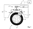
- eine schematische Darstellung einer erfindungsgemäßen Vorrichtung, die in einem Radkasten bzw. einem Rad eines Fahrzeugs angeordnet ist,
- Fig. 2
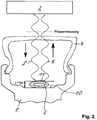
- einen Querschnitt eines Rades mit in einem Felgenbett integrierten kompressiblen Strukturelement zur Ermittlung eines Reifendrucks des Rades,
- Fig. 3
- eine Draufsicht auf einen Ausschnitt des kompressiblen Strukturelementes gemäß
Figur 3 , - Fig. 4
- einen Querschnitt durch das Rad mit einem als Mikrowellenhohlraumabsorber ausgebildeten Strukturelement, das in dem Felgenbett angeordnet ist zur Ermittlung des Reifendrucks,
- Fig. 5
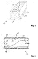
- eine perspektivische Darstellung des Mikrowellenhohlraumabsorbers,
- Fig. 6
- eine Seitenansicht des Mikrowellenhohlraumabsorbers und
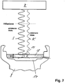
- Fig. 7
- einen Querschnitt des Rades, bei dem im Unterschied zu der Messung gemäß
Figur 4 der Mikrowellenhohlraumabsorber zur Radparametermessung benutzt wird. - Eine Vorrichtung zum Messen und/oder Überwachen von reifenbezogenen Messgrößen eines Fahrzeugs weist eine Sensoreinheit 1 auf, die im Wesentlichen eine Sende-/Empfangseinrichtung 2 umfasst, die in einem Radkasten 3 eines Fahrzeugs (KFZ) integriert ist. Die Sensoreinheit 1 kann mit einer ortsfern, vorzugsweise im Fahrzeug angeordneten Steuereinheit 4 über Signalleitungen, beispielsweise einen CAN-Bus, verbunden sein. Zur Messung bzw. Überwachung eines Reifendrucks eines Rades 5 des Fahrzeugs ist ein Strukturelement 6 als Messobjekt in einem durch einen Reifen 7 und durch eine Felge 8 des Rades 5 begrenzten Innenraum 9 angeordnet.
- Nach einer ersten Ausführungsform der Erfindung gemäß
Figur 2 ist das Strukturelement 6 als ein kompressibles Strukturelement ausgebildet, das in einem Felgenbett 10 der Felge 8 positioniert bzw. befestigt ist. - Wie aus
Figur 1 zu ersehen ist, weist die Sende-/Empfangseinrichtung 2 einen vektoriellen Netzwerkanalysator VNA, eine Auswerteeinheit 11, einen zwischen der Auswerteinheit 11 und dem Netzwerkanalysator VNA angeordneten digitale Signalprozessoreinheit DSP sowie eine Antenneneinheit 12 enthaltend eine Sende-/Empfangsantenne 13 und eine Empfangsantenne 14 auf. - Der Netzwerkanalysator VNA weist einen Oszillator auf, der ein sinusförmiges Messsignal im Mikrowellenfrequenzbereich von beispielsweise 300 MHz bis 300 GHz erzeugt, vorzugsweise zwischen 6,0 und 8,5 GHz. Die Sende-/Empfangseinrichtung 2 weist einen Mikroprozessor zur Signalverarbeitung und Steuerung sowie einen Bus-Schaltkreis zur leitungsgebundenen Datenübertragung über eine Bus-Verbindung mit einer dezentralen oder der zentralen ortsfern angeordneten Steuereinheit 4 auf. Vorzugsweise weist die Sende-/Empfangseinrichtung 2 zusätzlich noch eine DC-DC-Wandlereinheit auf. Der Netzwerkanalysator VNA weist ferner einen Prozessor sowie Messtore auf, wobei der Prozessor über Richtkoppler mit dem Messtoren verbunden ist. Somit kann der Netzwerkanalysator VNA ein Sendesignal S erzeugen, das über die Sende-/Empfangsantenne 13 der Antenneneinheit 12 an das kompressible Strukturelement 6 übertragen wird. Mittels der Sende-/Empfangsantenne 3 wird ein Reflexionssignal R, das an dem kompressiblen Strukturelement 6 reflektiert wird, empfangen und in der Auswerteeinheit 11 unter Ermittlung einer Phasendifferenz zwischen dem Sendesignal S und dem Reflexionssignal R ausgewertet.
- Zur Erhöhung der Messgenauigkeit weist das kompressible Strukturelement 6, das als kreisförmiger Endlosschlauch ausgebildet ist, der sich in Umfangsrichtung des Rades 5 unter Anlage an dem Felgenbett 10 erstreckt, außenseitig eine Anzahl von in Umfangsrichtung orientiert angeordneten ersten Reflektorelementen 15 auf. Diese ersten Reflektorelemente 15 sind in einem Abstand zueinander in Umfangsrichtung angeordnet. Die Länge der ersten Reflektorelemente 15 bestimmen die Arbeitsfrequenz bzw. die Frequenz des Sendesignals S. Während das kompressible Strukturelement 6 als ein Gummischlauch ausgebildet sein kann, kann das erste Reflektorelement 15 aus einem Metallmaterial bestehen. Das erste Reflektorelement 15 besteht aus einem mikrowellenabsorbierenden Material. Dies bewirkt, dass das erste Reflektorelement 15 im Betrag der Reflexionsmessung deutlich gegenüber dem ansonsten stark reflektierenden Hintergrund des Felgenbettes 10 hervortritt. Dies ist darin begründet, dass bei den Frequenzen, für die das Reflektorelement 15 eine Länge l1 von etwa/2 aufweist, die Wellen primär von diesem reflektiert werden. Der Anteil der nicht von diesem resonanten ersten Reflektorelement 15 reflektierten Wellen, transmittiert bei seiner Reflexion an dem Felgenbett 10 zweimal das mikrowellenabsorbierende Material 15 und wird dementsprechend abgedämpft. Folglich kann hierdurch die Felgenreflexion als Störgröße erheblich reduziert werden. Darüber hinaus kann eine Fensterung dadurch vereinfacht und das effektive Signal-Zu-Rausch-Verhältnis ansteigen. Darüber hinaus ist auch eine exakte Bestimmung der Arbeitsfrequenz des passiven Reflektorelementes 15 im Betrag der S11-Messung möglich. Die Anforderungen an die Fertigungsgenauigkeit des Reflektorelementes 15 können hierdurch verringert werden. Aus dem lokalen Maximum der S11-Messung lässt sich der exakte Frequenzpunkt für die Phasenmessung bestimmen.

- Hierzu ist es sinnvoll, dass die Sende-/Empfangsantenne 13 ausschließlich auf das Strukturelement 6 bzw. die ersten Reflektorelemente 15 ausgerichtet ist. Der maximale Erfassungsbereich in axialer Richtung ist durch eine Breite b1 des Strukturelementes 6 begrenzt. Diese Bedingung gilt, wenn der Reifendruck ausschließlich mit dem Strukturelement 6, aber nicht mit dem ersten Reflektorelement 15 gemessen wird.
- Erfolgt die Messung des Reifendrucks unter Einschluss der in der Länge l1 von/2 angeordneten streifenförmigen Reflektorelementen 15 auf dem Strukturelement 6, ist die Erfassungsbreite der Sende-/Empfangsantenne 13 auf eine Breite b2 der streifenförmigen Reflektorelemente 15 begrenzt. Vorteilhaft ist die Sensoreinheit 1 bei dieser Variante in der Lage, neben dem Reifendruck auch die Geschwindigkeit des Rades bzw. des Reifens zu messen.
- Die Sensoreinheit 1 ist geeignet, eine Einfedertiefe des Rades 5 zu messen. Hierzu erfolgt eine Phasenauswertung durch den Netzwerkanalysator VNA.
- Die Sende-/Empfangseinrichtung 2 sendet ein Sinussignal mit der Frequenz fi (i: Laufindex) zum Reifen aus. An der Oberfläche des Reifens wird dieses Sinussignal zu einem nicht unerheblichen Teil reflektiert, d.h. zurück gestrahlt. Die Sende-/Empfangseinrichtung 2 empfängt das reflektierte und in der Phase veränderte sinusförmige Signal und wertet die Phase ϕ(fi) aus. Diese Messung wird bei weiteren Frequenzen durchgeführt. Aus der Phase über der Sendefrequenz lässt sich dann die Entfernungsinformation ermitteln.
Im Hochfrequenz- und Mikrowellenbereich gilt für die Ausbreitung im Freiraum der Ausbreitungskoeffizient
- Es gilt somit für die gesamte Phasendrehung der Reflexionsmessung über die Entfernung ℓx für den Frequenzpunkt f1 am Eingang und am Empfänger:

- Gemessen wird die Phase nur im Eindeutigkeitsbereich von 360°. Folglich gilt für gesamten Phasenwert von rg in Abhängigkeit vom Messwert der Phase von rm:

Die Messwerte des Reflexionsfaktors liegt von einer unteren Frequenz f1u bis zu einer oberen Frequenz f1o als Phasenwert von rum und rom vor. Zwischen den verschiedenen Messpunkten soll es keine Phasensprünge geben, die sich in der praktischen Mathematik auch einfach eliminieren lassen.
Aus diesen beiden Messwerten und den bekannten zugehörigen Frequenzpunkten lässt sich die Steigung der Phase über der Frequenz ermitteln:
- Bei der beliebigen Frequenz fi gibt es aufgrund der Steigung eine Grundphasendrehung von

- Gleichung (5) lässt sich auch mit fo = fi und fu = 0Hz und den zugehörigen Phasenwerten aus der Gleichung (4) ableiten. Durch die folgende Bedingung

Es gilt für die Längenbestimmung der Entfernung ℓx basierend auf der Gleichung (2) für jeden Frequenzpunkt:
- Neben der exakten Lösung lässt sich rx auch durch eine einmalige Messung bei bekannter Länge bestimmen. In der Praxis wird Gleichung (7) für jeden gemessenen Frequenzpunkt ausgewertet, damit durch eine anschließende Mittelung stochastische Fehler minimiert werden.
Die Präzision dieser Messung steigt mit der Bandbreite (f1o - f1u) und der Anzahl der Messungen. - Die nunmehr berechnete Entfernung ℓx ist proportional zur Federtiefe. Dieser Werte wird im Weiteren auch bei den anderen Messungen benötigt, wie im Abschnitt "Fensterung" noch erklärt wird.
- Zur Bestimmung des Reifendrucks wird die Phase des Reflexionssignals R (S11-Messung) mit der Phase des Sendesignals S verglichen. Ist das beispielsweise als Gummischlauch ausgebildete Strukturelement 6 nicht komprimiert, so befindet sich deutlich mehr Gummi in der Funkstrecke als im komprimierten Zustand. Über die sich ändernde Menge an dielektrischem Material verändern sich die Phasenmessresultate, die somit proportional zum Druck sind. Die Messung der Verformung des Strukturelementes 6 wird durch die aufgebrachten Reflektorelemente 15 vereinfacht, da sich bei der Resonanzfrequenz der Reflektorelemente 15 diese gezielt zur Phasenmessung heranziehen lassen. Hierdurch kann die Genauigkeit der Messung erhöht bzw. die Messgenauigkeitsanforderung an den Netzwerkanalysator VNA reduziert werden.
- Der Schmutz oder andere Störgrößen wie Felgenreflexion, Phasendrehung durch Reifen, Feuchtigkeitsfilm auf dem Gehäuse der Sende-/Empfangseinrichtung 2 verändert die Übertragungseigenschaften im Betrag und in der Phase. Dieser störende Effekt kann durch eine Fensterung für alle Messungen eliminiert werden. Hierzu sind Auswertemittel vorgesehen, dass das Reflexionssignal R durch inverse Fourier-Transformation in den Zeitbereich transformiert wird, dann die bekannten Zeitbereiche (Oberfläche des Gehäuses ist gegeben und fest und der Reifenabstand wurde gemessen) herausgefenstert und dann das somit gefilterte S11-Signal durch diskrete Fourier-Transformation in den Frequenzbereich zurücktransformiert wird. Nun ist das komplexe Reflexionsverhalten, das sich auf der Oberfläche der Felge 8 ergibt, das dominante Signal. Dieses Verfahren wird erst durch die Erfassung der Messwerte nach Betrag und Phase, d.h. vektoriell, möglich.
Nach einer weiteren Ausführungsform der Erfindung kann das kompressible Strukturelement 6 zusätzlich zweite Reflektorelemente 16 aufweisen, die in Axialrichtung des Reifens 7 bzw. der Felge 8 orientiert angeordnet sind. Die zweiten Reflektorelemente 16 sind somit senkrecht zu den ersten Reflektorelementen 15 angeordnet bzw. weisen die gleiche Länge l2 =/2 auf wie die ersten Reflektorelemente 15. Da sie um 90° gedreht sind, ist eine horizontale Polarisation und mittels der ersten Reflektorelemente 15 eine vertikale Polarisation gewährleistet. Hierdurch kann zusätzlich noch der Einschlagwinkel des Rades 5 gemessen werden.
Nach einer weiteren Ausführungsform der Erfindung gemäßFigur 4 kann statt eines kompressiblen Strukturelementes 6 ein Mikrowellenhohlraumabsorber 17 vorgesehen sein, der von einem offenporigen Schaumstoffschicht 18 überdeckt sein kann, an dessen Außenseite die Anzahl von ersten Reflektorelementen 15 und/oder zweiten Reflektorelementen 16 angeordnet ist. Der Mikrowellenhohlraumabsorber 17 ist wie die Schaumstoffschicht 18 ringförmig angeordnet. Der Mikrowellenhohlraumabsorber 17 liegt unmittelbar im Felgenbett 10 der Felge 8 an. Wie aus denFiguren 5 und 6 deutlich wird, weist der Mikrowellenhohlraumabsorber 17 ein Gehäuse 19 enthaltend eine Längswandung 20 auf, die sich ringförmig entlang des Felgenbettes 10 erstreckt. Der Mikrowellenhohlraumabsorber 17 erstreckt sich teilkreisförmig in Umfangsrichtung, wobei der Abstand zwischen zwei endseitigen flexiblen Membranen 21 durch die Resonanzfrequenz vorgegeben ist. Die Länge I des Mikrowellenhohlraumabsorbers 17 beträgt somit/2. Auf einer zum Felgenbett 10 abgewandten Seite des Gehäuses 19 erstreckt sich außenseitig der Längswandung 20 eine Antenne 22. Die Antenne 22 ist über einen Schlitz 23 der Längswandung 20 an einer Innenseite der Längswandung 20 kontaktiert. Die Antenne 22 ist über eine Isolierung 24 auf der Längswandung 20 des Gehäuses 19 befestigt. Hiermit wird ein druckabhängiger Mikrowellenresonator bereitgestellt, dessen Resonanzfrequenz abhängig ist von dem Druck des Reifens 7. Die flexiblen Membranen 21 können beispielsweise aus einem biaxial orientierten Polyethylenterephthalat-Material bzw.- Folie (bo-PET, Mylaer) gebildet sein. Die Antenne 22 ist als eine planare Antenne ausgebildet. - Damit dieses Messsystem die notwendige Übersprecherisolation zwischen dem Sendesignal und dem Empfänger hat, ist es notwendig einmalig in der Produktion eine Systemfehlerkorrektur durchzuführen, wie es bei jedem kaufbaren VNA der Fall ist. Jedoch muss diese im Freiraum durchgeführt werden. Hierfür in Frage kommende Verfahren sind in dem Dokument: " Heuermann, H., Sichere Verfahren zur Kalibrierung von Netzwerkanalysatoren für koaxiale und planare Leitungssysteme, Dissertationsschrift, Institut für Hochfrequenztechnik, Ruhr-Universität Bochum, 1995, ISBN 3-8265-1495-5 )" publiziert. Vorzugsweise lässt sich das Zweitorverfahren LNN verwenden. Alternativ lässt sich aus dem dargestellten S-3-R-Verfahren ein M-3-R-Verfahren herleiten, das sich ebenfalls für Freiraummessungen einsetzen lässt.
Beim M-3-R-Verfahren werden vier Eintormessungen durchgeführt: - 1) M-Messung: Antenne wird Richtung Himmel (oder Absorber) ausgerichtet.
- 2) 3-R-Messungen: Die Reflexion an einem Tripelspiegel wird in 3 Stellungen bei bekannten Abständen vermessen.
- Diese VNA-Kalibrierung ist vor einer beschriebenen Fensterung durchzuführen.
- Nach einer weiteren Ausführungsform der Erfindung gemäß
Figur 7 kann die Sende-/Empfangseinrichtung 2 auch genutzt werden, um ein Sendesignal S in Frequenzen außerhalb des Arbeitsbereiches des Mikrowellenhohlraumabsorbers 17 zu senden und zu empfangen zur Radparametermessung. Der Mikrowellenhohlraumabsorber 17 dämpft das Reflexionssignal R' dieser Frequenzen gegenüber der Resonatorreflexion. Damit können die Resonatoren in den Messergebnissen leichter aufgefunden werden. - Die ersten Reflektorelemente 15 und die zweiten Refelektorelemente 16 bewirken, dass bei Geradeauslauf der Räder (kein Lenkeinschlag) nur die Reflexionen von den ersten Reflektorelementen 15 erfasst werden. Bei einem Lenkeinschlag treten zusätzliche Reflexionen an den zweiten Reflektorelementen 16 an. Bei einem Lenkeinschlag von 45° sind die Reflexionsanteile der ersten Reflektorelemente 15 und der zweiten Reflektorelemente 16 gleichgroß.
- Zur Messung des Lenkeinschlags kann die Sende-/Empfangseinrichtung 2 alternativ auch die zusätzliche Empfangsantenne 14 aufweisen, deren Polarisationsebene um 90° zu der Empfangsantenne 13 gedreht ist. Bei Geradeauslauf empfängt die Antenne 14 kein Signal. Mit zunehmendem Lenkeinschlag wird das Signal der Empfangsantenne 14 größer und an der Empfangsantenne 13 kleiner. Die Richtung, ob nach rechts oder links gelenkt wird, erhält man aus dem Phasenunterschied zwischen den beiden ermittelten Reflexionssignalen R der ersten Empfangsantenne 13 und der zweiten Empfangsantenne 14.
- Soll die Sensoreinheit Fremdkörper in oder an dem Reifen 7 erkennen können, muss die gesamte Breite des Reifens 7 erfasst werden. Die Sende-/Empfangsantenne 13 muss eine Richtcharakteristik besitzen, die einerseits den gesamten Reifen in der Breite überdeckt und andererseits erfasste Segmente in Umfangsrichtung des Reifens 7 möglichst schmal sind. Somit kann ein Scannen des Reifens 7 in Umfangsrichtung erfolgen. Bei Vorhandensein eines fremden Gegenstandes, beispielsweise eines Nagels, in einem Segment des Reifens 7, ergibt sich ein anderer Reflexionswert R im Vergleich zu den anderen in Umfangsrichtung erfassten Segmenten des Reifens 7.
- Die Ansteuerung der Sensoreinheit 1 erfolgt vorzugsweise mittels eines Pseudozufallszahlengenerators, so dass die jeweils den Rädern 5 zugeordneten Sende-/Empfangseinrichtung 2 zeitversetzt angesteuert werden und eine gegenseitige Störung vermieden wird.
Claims (10)
- Vorrichtung zum Messen und/oder Überwachen von reifenbezogenen Messgrößen eines Fahrzeugs mit einer Sensoreinheit (1) zum Senden, Empfangen und Verarbeiten von Signalen, wobei von einer Antenneneinheit der Sensoreinheit (1) ein Sendesignal (S) in Richtung eines Messobjektes (7) abstrahlbar ist und wobei ein von dem Messobjekt reflektiertes Reflexionssignal (R, R') empfangbar und auswertbar ist, und die Sensoreinheit (1) eine Sende-/Empfangseinrichtung (2) aufweist, mittels derer ein Reflexionsfaktor (S11), der als Quotient aus dem an dem Messobjekt reflektierten Reflexionssignal (R) und dem Sendesignal (S) ausgebildet ist, messbar ist und mittels dessen eine Phasendifferenz zwischen dem Sendesignal (S) und dem Reflexionssignal (R) bestimmbar ist, und die Sende-/Empfangseinrichtung (2) einen vektoriellen Netzwerkanalysator (VNA) und eine Auswerteeinheit (11) aufweist, so dass durch Erfassung der Phasendifferenz zwischen dem Sendesignal (S) und dem Reflexionssignal (R) eine Entfernung zu dem Messobjekt (7) ermittelbar ist, dadurch gekennzeichnet, dass in Umfangsrichtung eines Rades orientierte erste Reflektorelemente (15) und quer zu den ersten Reflektorelementen (15) angeordnete zweite Reflektorelemente (16) vorgesehen sind, so dass das Reflexionssignal (R') in Abhängigkeit von einem Lenkeinschlag des Rades (5) veränderlich ist.
- Vorrichtung nach Anspruch 1, dadurch gekennzeichnet, dass die Phasendifferenz für eine Mehrzahl von gleichen und/oder unterschiedlichen Frequenzwerten und/oder in einer vorgegebenen Bandbreite durchführbar ist und dass das Messobjekt ein Reifen (7) ist, so dass aus der ermittelten Entfernung zwischen Sende-/Empfangseinrichtung (2) und dem Reifen (7) eine Federtiefe des Reifens (7) bestimmbar ist.
- Vorrichtung nach Anspruch 1 oder 2, dadurch gekennzeichnet, dass die Auswerteeinheit (11) Auswertemittel aufweist, so dass das im Betrag und Phase vorliegende Reflexionssignal (R) durch inverse Fourier-Transformation in den Zeitbereich transformierbar, in einem Signalprozessor der Sende-/Empfangseinheit (2) ein durch die Lage derselben und einem ermittelten Abstand derselben zu dem Messobjekt bestimmten Zeitbereich gefenstert und dass das gefilterte reflektierte Signal (P) durch Fourier-Transformation in den Frequenzbereich zurücktransformierbar ist.
- Vorrichtung nach einem der Ansprüche 1 bis 3, dadurch gekennzeichnet, dass die Sende-/Empfangseinrichtung (2) in einem Radkasten (3) eines Fahrzeugs angeordnet ist und dass das Rad (5) ein kompressibles Strukturelement (6) aufweist, das innerhalb eines durch einen Reifen (7) und einer Felge (8) des Rades (5) begrenzten Innenraumes (9) in Umfangsrichtung des Rades (5) angeordnet ist, und dass die Antenneneinheit (12) der Sende-/Empfangseinrichtung (2) auf das Strukturelement (6) ausgerichtet ist.
- Vorrichtung nach Anspruch 4, dadurch gekennzeichnet, dass das kompressible Strukturelement (6) als ein kreisförmiger Endlosschlauch ausgebildet ist, der in einem Felgenbett (10) der Felge (8) angeordnet und/oder an dieser befestigt ist.
- Vorrichtung nach Anspruch 4 oder 5, dadurch gekennzeichnet, dass das kompressible Strukturelement (6) außenseitig mit einer Anzahl von Reflektorelementen (15, 16) versehen ist.
- Vorrichtung nach Anspruch 5 oder 6, dadurch gekennzeichnet, dass an dem Felgenbett (10) als Messobjekt ein druckabhängiger Mikrowellenhohlraumabsorber (17) mit einem Gehäuse (19) enthaltend eine Längswandung (20), an der eine Antenne (22) befestigt ist, und enthaltend an gegenüberliegenden Seiten der Längswandung (20) angeordneten flexiblen Membranen (21), so dass durch Ermittlung eine Resonanzfrequenz ein Luftdruck des Reifens (7) ableitbar ist.
- Vorrichtung nach einem der Ansprüche 1 bis 7, dadurch gekennzeichnet, dass die Sensoreinheit (1) über ein Pseudozufallszahlengenerator ansteuerbar ist, so dass die jeweils den Rädern (5) zugeordneten Sende-/Empfangseinrichtung (2) zeitlich versetzt zueinander beaufschlagbar sind.
- Vorrichtung nach einem der Ansprüche 1 bis 8, dadurch gekennzeichnet, dass die Sende-/Empfangseinheit (2) eine zusätzliche Antenne (14) aufweist, deren Polarisationsebene um 90° zu der Antenne (13) gedreht ist, so dass aus einem Phasenunterschied durch diese beiden Antennen erfassten Reflexionssignale (R) ein Lenkeinschlag des Rades (5) ermittelbar ist.
- Vorrichtung nach einem der Ansprüche 1 bis 9, dadurch gekennzeichnet, dass die Sende-/Empfangsantenne (13) der Sende-/Empfangseinheit (2) auf eine Breite (b1) der Felge (8) und/oder des Reifens (7) ausgerichtet ist, so dass durch Phasendifferenz des Reflexionssignals (R) zum Sendesignal (S) ein Fremdkörper an dem Reifen (7) ermittelbar ist.
Applications Claiming Priority (2)
| Application Number | Priority Date | Filing Date | Title |
|---|---|---|---|
| DE102015100890 | 2015-01-22 | ||
| PCT/DE2016/100021 WO2016116098A1 (de) | 2015-01-22 | 2016-01-19 | MESS- UND ÜBERWACHUNGSVORRICHTUNG FÜR REIFENBEZOGENE GRÖßEN EINES FAHRZEUGS |
Publications (2)
| Publication Number | Publication Date |
|---|---|
| EP3247576A1 EP3247576A1 (de) | 2017-11-29 |
| EP3247576B1 true EP3247576B1 (de) | 2018-12-12 |
Family
ID=55538154
Family Applications (1)
| Application Number | Title | Priority Date | Filing Date |
|---|---|---|---|
| EP16709965.4A Not-in-force EP3247576B1 (de) | 2015-01-22 | 2016-01-19 | Vorrichtung zum messen von reifenbezogenen grössen eines fahrzeugs |
Country Status (4)
| Country | Link |
|---|---|
| US (1) | US10137744B2 (de) |
| EP (1) | EP3247576B1 (de) |
| CN (1) | CN107430185B (de) |
| WO (1) | WO2016116098A1 (de) |
Cited By (1)
| Publication number | Priority date | Publication date | Assignee | Title |
|---|---|---|---|---|
| DE102022127443A1 (de) | 2022-10-19 | 2024-04-25 | Bayerische Motoren Werke Aktiengesellschaft | Verfahren zum Prognostizieren eines Drucks in einem Fahrzeugreifen sowie Fahrzeug |
Families Citing this family (8)
| Publication number | Priority date | Publication date | Assignee | Title |
|---|---|---|---|---|
| DE102014007643A1 (de) * | 2014-05-23 | 2015-11-26 | Astyx Gmbh | Abstandmessvorrichtung, insbesondere für metallische und dielektrische Zielobjekte |
| US11453259B2 (en) | 2018-02-01 | 2022-09-27 | Pixart Imaging Inc. | Object surface managing method and object surface managing system |
| TWI656044B (zh) * | 2018-02-27 | 2019-04-11 | 為升電裝工業股份有限公司 | 具有外殼保護之胎壓偵測器 |
| US10820474B2 (en) | 2018-10-11 | 2020-11-03 | Cnh Industrial Canada, Ltd. | System for estimating field conditions and associated methods for adjusting operating parameters of an agricultural machine based on estimated field conditions |
| EP3871003B1 (de) * | 2018-10-24 | 2025-02-26 | ABB Schweiz AG | Radarsensor und roboter |
| FR3120207A1 (fr) * | 2021-02-26 | 2022-09-02 | Continental Automotive Gmbh | Procédé pour la localisation des roues d’un véhicule automobile |
| EP4082809B1 (de) * | 2021-04-27 | 2023-06-07 | Volvo Truck Corporation | Reifen mit einer elektronischen schaltung zur messung der profiltiefe, anordnung und fahrzeug |
| KR20230033527A (ko) * | 2021-09-01 | 2023-03-08 | 현대자동차주식회사 | 타이어 이상 상태 감지 장치 및 방법 |
Family Cites Families (10)
| Publication number | Priority date | Publication date | Assignee | Title |
|---|---|---|---|---|
| US3873965A (en) * | 1974-04-18 | 1975-03-25 | George E Garcia | Tire pressure monitoring system |
| DE4117158A1 (de) * | 1991-05-25 | 1992-11-26 | Telefunken Systemtechnik | Beruehrungsloser abstandsmesssensor |
| US5216372A (en) * | 1991-07-29 | 1993-06-01 | Colorado State University Research Foundation | Microwave steel belt location sensor for tires |
| DE4326976A1 (de) * | 1993-08-11 | 1995-02-16 | Manfred Ludewig | Verfahren und Vorrichtung zum Überwachen von Fahrzeugreifen |
| US20020189336A1 (en) | 2001-06-15 | 2002-12-19 | Mcewan Technologies, Llc | Radar monitoring system for tires and wheels |
| WO2003027709A1 (de) * | 2001-09-21 | 2003-04-03 | Siemens Aktiengesellschaft | Nahbereichs-radarsensor mit phasendifferenz-messung |
| DE102005011577A1 (de) * | 2005-03-14 | 2006-09-21 | Robert Bosch Gmbh | Vorrichtung zur Zustandserkennung eines Reifens an einem Rad |
| WO2008149422A1 (ja) * | 2007-06-05 | 2008-12-11 | Fujitsu Limited | センサによる検出値を蓄積するアクティブ非接触情報記憶装置 |
| DE102009013458A1 (de) | 2009-03-18 | 2010-09-23 | Norbert Michel | Sensor auf Basis reflektierter Hochfrequenz-Strahlung |
| WO2010120558A2 (en) * | 2009-03-31 | 2010-10-21 | Reading Leslie J | Buried object detector |
-
2016
- 2016-01-19 CN CN201680013208.4A patent/CN107430185B/zh not_active Expired - Fee Related
- 2016-01-19 EP EP16709965.4A patent/EP3247576B1/de not_active Not-in-force
- 2016-01-19 US US15/544,954 patent/US10137744B2/en not_active Expired - Fee Related
- 2016-01-19 WO PCT/DE2016/100021 patent/WO2016116098A1/de not_active Ceased
Non-Patent Citations (1)
| Title |
|---|
| None * |
Cited By (1)
| Publication number | Priority date | Publication date | Assignee | Title |
|---|---|---|---|---|
| DE102022127443A1 (de) | 2022-10-19 | 2024-04-25 | Bayerische Motoren Werke Aktiengesellschaft | Verfahren zum Prognostizieren eines Drucks in einem Fahrzeugreifen sowie Fahrzeug |
Also Published As
| Publication number | Publication date |
|---|---|
| CN107430185B (zh) | 2020-10-30 |
| EP3247576A1 (de) | 2017-11-29 |
| WO2016116098A1 (de) | 2016-07-28 |
| US20170368892A1 (en) | 2017-12-28 |
| US10137744B2 (en) | 2018-11-27 |
| CN107430185A (zh) | 2017-12-01 |
Similar Documents
| Publication | Publication Date | Title |
|---|---|---|
| EP3247576A1 (de) | MESS- UND ÜBERWACHUNGSVORRICHTUNG FÜR REIFENBEZOGENE GRÖßEN EINES FAHRZEUGS | |
| EP2629113B1 (de) | Radarsystem mit anordnungen und verfahren zur entkopplung von sende- und empfangssignalen sowie unterdrückung von störeinstrahlungen | |
| DE102006006781B4 (de) | FMCW-Radarvorrichtung und Verfahren zur Erfassung einer Störung | |
| EP2092368B1 (de) | Verfahren und vorrichtung zum erkennen von niederschlag mittels radar | |
| EP3143712B1 (de) | Verfahren zur kalibrierung eines mimo-radarsensors für kraftfahrzeuge | |
| DE102009016479B4 (de) | Verfahren für ein Radarsystem zur Vermeidung von durch Störeinstrahlungen bzw. -einkopplungen verursachten Fehlreaktionen | |
| DE102009016480A1 (de) | Radarsystem zur Unterdrückung von Mehrdeutigkeiten bei der Bestimmung von Objektmaßen | |
| WO2015185058A1 (de) | Radarsystem mit optimierter speicherung von zwischendaten | |
| DE102017207648B4 (de) | Verfahren und Vorrichtung zur Messung einer Schichtdicke eines Objekts | |
| EP3076186A1 (de) | Bestimmung von pegel und fliessgeschwindigkeit eines mediums | |
| DE102019207113A1 (de) | Verschiedenartige Erfassung unter Verwendung unterschiedlicher Sensorarten | |
| DE102013213340A1 (de) | Bestimmung einer Distanz und einer Fließgeschwindigkeit eines Mediums | |
| DE102007008944A1 (de) | Radarsystem zu Bestimmung der Länge von Objekten | |
| DE102017214964B4 (de) | Verfahren zur Ermittlung einer Umfeldkarte in einem Kraftfahrzeug und Kraftfahrzeug | |
| EP1624278B1 (de) | Luftfeder mit einer Messeinrichtung zur Abstands-Bestimmung von Kraftfahrzeugteilen | |
| EP4105679A2 (de) | Radarmesseinrichtung und -verfahren mit abgespeicherten reflektoridentitätsangaben | |
| WO2019219328A1 (de) | Messvorrichtung zur dämpfungsmessung von bauteilen | |
| EP1877825B1 (de) | Verfahren und vorrichtung zur bestimmung eines abstands zu einem zielobjekt | |
| EP3136124B1 (de) | Verfahren zum betrieb von radarsensoren in einem kraftfahrzeug und kraftfahrzeug | |
| EP3916372A1 (de) | Vermessungsvorrichtung | |
| DE102018124019A1 (de) | Verfahren zur Korrektur von fehlerhaften Erfassungssignalen | |
| EP1904804B1 (de) | Messvorrichtung zum elektromagnetischen messen einer wanddicke | |
| EP0908742B1 (de) | Verfahren zur Spektralanalyse von Dopplersignalen | |
| DE102020105366A1 (de) | Radarsystem und Verfahren zum Betreiben eines Radarsystems | |
| DE102005021226A1 (de) | Vorrichtung und Verfahren zur berührungslosen Geschwindigkeitsmessung eines Fahrzeuges |
Legal Events
| Date | Code | Title | Description |
|---|---|---|---|
| STAA | Information on the status of an ep patent application or granted ep patent |
Free format text: STATUS: THE INTERNATIONAL PUBLICATION HAS BEEN MADE |
|
| PUAI | Public reference made under article 153(3) epc to a published international application that has entered the european phase |
Free format text: ORIGINAL CODE: 0009012 |
|
| STAA | Information on the status of an ep patent application or granted ep patent |
Free format text: STATUS: REQUEST FOR EXAMINATION WAS MADE |
|
| 17P | Request for examination filed |
Effective date: 20170809 |
|
| AK | Designated contracting states |
Kind code of ref document: A1 Designated state(s): AL AT BE BG CH CY CZ DE DK EE ES FI FR GB GR HR HU IE IS IT LI LT LU LV MC MK MT NL NO PL PT RO RS SE SI SK SM TR |
|
| AX | Request for extension of the european patent |
Extension state: BA ME |
|
| DAV | Request for validation of the european patent (deleted) | ||
| DAX | Request for extension of the european patent (deleted) | ||
| GRAP | Despatch of communication of intention to grant a patent |
Free format text: ORIGINAL CODE: EPIDOSNIGR1 |
|
| STAA | Information on the status of an ep patent application or granted ep patent |
Free format text: STATUS: GRANT OF PATENT IS INTENDED |
|
| RIC1 | Information provided on ipc code assigned before grant |
Ipc: G01N 22/00 20060101ALI20180531BHEP Ipc: G01L 17/00 20060101ALI20180531BHEP Ipc: G01S 7/02 20060101ALI20180531BHEP Ipc: G01S 7/35 20060101ALI20180531BHEP Ipc: G01S 13/75 20060101ALI20180531BHEP Ipc: B60C 23/04 20060101AFI20180531BHEP Ipc: G01R 27/28 20060101ALI20180531BHEP Ipc: G01S 7/40 20060101ALI20180531BHEP Ipc: G01M 17/02 20060101ALI20180531BHEP Ipc: H01Q 1/22 20060101ALI20180531BHEP Ipc: G01S 13/36 20060101ALI20180531BHEP Ipc: G01S 13/88 20060101ALI20180531BHEP |
|
| INTG | Intention to grant announced |
Effective date: 20180704 |
|
| GRAS | Grant fee paid |
Free format text: ORIGINAL CODE: EPIDOSNIGR3 |
|
| GRAA | (expected) grant |
Free format text: ORIGINAL CODE: 0009210 |
|
| STAA | Information on the status of an ep patent application or granted ep patent |
Free format text: STATUS: THE PATENT HAS BEEN GRANTED |
|
| AK | Designated contracting states |
Kind code of ref document: B1 Designated state(s): AL AT BE BG CH CY CZ DE DK EE ES FI FR GB GR HR HU IE IS IT LI LT LU LV MC MK MT NL NO PL PT RO RS SE SI SK SM TR |
|
| REG | Reference to a national code |
Ref country code: GB Ref legal event code: FG4D Free format text: NOT ENGLISH |
|
| REG | Reference to a national code |
Ref country code: CH Ref legal event code: EP |
|
| REG | Reference to a national code |
Ref country code: AT Ref legal event code: REF Ref document number: 1075455 Country of ref document: AT Kind code of ref document: T Effective date: 20181215 |
|
| REG | Reference to a national code |
Ref country code: DE Ref legal event code: R096 Ref document number: 502016002845 Country of ref document: DE |
|
| REG | Reference to a national code |
Ref country code: IE Ref legal event code: FG4D Free format text: LANGUAGE OF EP DOCUMENT: GERMAN |
|
| REG | Reference to a national code |
Ref country code: NL Ref legal event code: MP Effective date: 20181212 |
|
| REG | Reference to a national code |
Ref country code: LT Ref legal event code: MG4D |
|
| PG25 | Lapsed in a contracting state [announced via postgrant information from national office to epo] |
Ref country code: ES Free format text: LAPSE BECAUSE OF FAILURE TO SUBMIT A TRANSLATION OF THE DESCRIPTION OR TO PAY THE FEE WITHIN THE PRESCRIBED TIME-LIMIT Effective date: 20181212 Ref country code: LT Free format text: LAPSE BECAUSE OF FAILURE TO SUBMIT A TRANSLATION OF THE DESCRIPTION OR TO PAY THE FEE WITHIN THE PRESCRIBED TIME-LIMIT Effective date: 20181212 Ref country code: NO Free format text: LAPSE BECAUSE OF FAILURE TO SUBMIT A TRANSLATION OF THE DESCRIPTION OR TO PAY THE FEE WITHIN THE PRESCRIBED TIME-LIMIT Effective date: 20190312 Ref country code: FI Free format text: LAPSE BECAUSE OF FAILURE TO SUBMIT A TRANSLATION OF THE DESCRIPTION OR TO PAY THE FEE WITHIN THE PRESCRIBED TIME-LIMIT Effective date: 20181212 Ref country code: BG Free format text: LAPSE BECAUSE OF FAILURE TO SUBMIT A TRANSLATION OF THE DESCRIPTION OR TO PAY THE FEE WITHIN THE PRESCRIBED TIME-LIMIT Effective date: 20190312 Ref country code: HR Free format text: LAPSE BECAUSE OF FAILURE TO SUBMIT A TRANSLATION OF THE DESCRIPTION OR TO PAY THE FEE WITHIN THE PRESCRIBED TIME-LIMIT Effective date: 20181212 Ref country code: LV Free format text: LAPSE BECAUSE OF FAILURE TO SUBMIT A TRANSLATION OF THE DESCRIPTION OR TO PAY THE FEE WITHIN THE PRESCRIBED TIME-LIMIT Effective date: 20181212 |
|
| PG25 | Lapsed in a contracting state [announced via postgrant information from national office to epo] |
Ref country code: RS Free format text: LAPSE BECAUSE OF FAILURE TO SUBMIT A TRANSLATION OF THE DESCRIPTION OR TO PAY THE FEE WITHIN THE PRESCRIBED TIME-LIMIT Effective date: 20181212 Ref country code: AL Free format text: LAPSE BECAUSE OF FAILURE TO SUBMIT A TRANSLATION OF THE DESCRIPTION OR TO PAY THE FEE WITHIN THE PRESCRIBED TIME-LIMIT Effective date: 20181212 Ref country code: SE Free format text: LAPSE BECAUSE OF FAILURE TO SUBMIT A TRANSLATION OF THE DESCRIPTION OR TO PAY THE FEE WITHIN THE PRESCRIBED TIME-LIMIT Effective date: 20181212 Ref country code: GR Free format text: LAPSE BECAUSE OF FAILURE TO SUBMIT A TRANSLATION OF THE DESCRIPTION OR TO PAY THE FEE WITHIN THE PRESCRIBED TIME-LIMIT Effective date: 20190313 |
|
| PG25 | Lapsed in a contracting state [announced via postgrant information from national office to epo] |
Ref country code: NL Free format text: LAPSE BECAUSE OF FAILURE TO SUBMIT A TRANSLATION OF THE DESCRIPTION OR TO PAY THE FEE WITHIN THE PRESCRIBED TIME-LIMIT Effective date: 20181212 |
|
| PG25 | Lapsed in a contracting state [announced via postgrant information from national office to epo] |
Ref country code: PL Free format text: LAPSE BECAUSE OF FAILURE TO SUBMIT A TRANSLATION OF THE DESCRIPTION OR TO PAY THE FEE WITHIN THE PRESCRIBED TIME-LIMIT Effective date: 20181212 Ref country code: CZ Free format text: LAPSE BECAUSE OF FAILURE TO SUBMIT A TRANSLATION OF THE DESCRIPTION OR TO PAY THE FEE WITHIN THE PRESCRIBED TIME-LIMIT Effective date: 20181212 Ref country code: PT Free format text: LAPSE BECAUSE OF FAILURE TO SUBMIT A TRANSLATION OF THE DESCRIPTION OR TO PAY THE FEE WITHIN THE PRESCRIBED TIME-LIMIT Effective date: 20190412 |
|
| PG25 | Lapsed in a contracting state [announced via postgrant information from national office to epo] |
Ref country code: SK Free format text: LAPSE BECAUSE OF FAILURE TO SUBMIT A TRANSLATION OF THE DESCRIPTION OR TO PAY THE FEE WITHIN THE PRESCRIBED TIME-LIMIT Effective date: 20181212 Ref country code: SM Free format text: LAPSE BECAUSE OF FAILURE TO SUBMIT A TRANSLATION OF THE DESCRIPTION OR TO PAY THE FEE WITHIN THE PRESCRIBED TIME-LIMIT Effective date: 20181212 Ref country code: EE Free format text: LAPSE BECAUSE OF FAILURE TO SUBMIT A TRANSLATION OF THE DESCRIPTION OR TO PAY THE FEE WITHIN THE PRESCRIBED TIME-LIMIT Effective date: 20181212 Ref country code: IS Free format text: LAPSE BECAUSE OF FAILURE TO SUBMIT A TRANSLATION OF THE DESCRIPTION OR TO PAY THE FEE WITHIN THE PRESCRIBED TIME-LIMIT Effective date: 20190412 Ref country code: RO Free format text: LAPSE BECAUSE OF FAILURE TO SUBMIT A TRANSLATION OF THE DESCRIPTION OR TO PAY THE FEE WITHIN THE PRESCRIBED TIME-LIMIT Effective date: 20181212 |
|
| REG | Reference to a national code |
Ref country code: CH Ref legal event code: PL |
|
| REG | Reference to a national code |
Ref country code: DE Ref legal event code: R097 Ref document number: 502016002845 Country of ref document: DE |
|
| PG25 | Lapsed in a contracting state [announced via postgrant information from national office to epo] |
Ref country code: LU Free format text: LAPSE BECAUSE OF NON-PAYMENT OF DUE FEES Effective date: 20190119 |
|
| REG | Reference to a national code |
Ref country code: BE Ref legal event code: MM Effective date: 20190131 |
|
| PLBE | No opposition filed within time limit |
Free format text: ORIGINAL CODE: 0009261 |
|
| STAA | Information on the status of an ep patent application or granted ep patent |
Free format text: STATUS: NO OPPOSITION FILED WITHIN TIME LIMIT |
|
| REG | Reference to a national code |
Ref country code: IE Ref legal event code: MM4A |
|
| PG25 | Lapsed in a contracting state [announced via postgrant information from national office to epo] |
Ref country code: SI Free format text: LAPSE BECAUSE OF FAILURE TO SUBMIT A TRANSLATION OF THE DESCRIPTION OR TO PAY THE FEE WITHIN THE PRESCRIBED TIME-LIMIT Effective date: 20181212 Ref country code: DK Free format text: LAPSE BECAUSE OF FAILURE TO SUBMIT A TRANSLATION OF THE DESCRIPTION OR TO PAY THE FEE WITHIN THE PRESCRIBED TIME-LIMIT Effective date: 20181212 Ref country code: MC Free format text: LAPSE BECAUSE OF FAILURE TO SUBMIT A TRANSLATION OF THE DESCRIPTION OR TO PAY THE FEE WITHIN THE PRESCRIBED TIME-LIMIT Effective date: 20181212 |
|
| 26N | No opposition filed |
Effective date: 20190913 |
|
| PG25 | Lapsed in a contracting state [announced via postgrant information from national office to epo] |
Ref country code: BE Free format text: LAPSE BECAUSE OF NON-PAYMENT OF DUE FEES Effective date: 20190131 |
|
| PG25 | Lapsed in a contracting state [announced via postgrant information from national office to epo] |
Ref country code: LI Free format text: LAPSE BECAUSE OF NON-PAYMENT OF DUE FEES Effective date: 20190131 Ref country code: CH Free format text: LAPSE BECAUSE OF NON-PAYMENT OF DUE FEES Effective date: 20190131 |
|
| PG25 | Lapsed in a contracting state [announced via postgrant information from national office to epo] |
Ref country code: IE Free format text: LAPSE BECAUSE OF NON-PAYMENT OF DUE FEES Effective date: 20190119 |
|
| PG25 | Lapsed in a contracting state [announced via postgrant information from national office to epo] |
Ref country code: TR Free format text: LAPSE BECAUSE OF FAILURE TO SUBMIT A TRANSLATION OF THE DESCRIPTION OR TO PAY THE FEE WITHIN THE PRESCRIBED TIME-LIMIT Effective date: 20181212 |
|
| PG25 | Lapsed in a contracting state [announced via postgrant information from national office to epo] |
Ref country code: MT Free format text: LAPSE BECAUSE OF FAILURE TO SUBMIT A TRANSLATION OF THE DESCRIPTION OR TO PAY THE FEE WITHIN THE PRESCRIBED TIME-LIMIT Effective date: 20181212 |
|
| PGFP | Annual fee paid to national office [announced via postgrant information from national office to epo] |
Ref country code: FR Payment date: 20210120 Year of fee payment: 6 Ref country code: IT Payment date: 20210129 Year of fee payment: 6 |
|
| PG25 | Lapsed in a contracting state [announced via postgrant information from national office to epo] |
Ref country code: CY Free format text: LAPSE BECAUSE OF FAILURE TO SUBMIT A TRANSLATION OF THE DESCRIPTION OR TO PAY THE FEE WITHIN THE PRESCRIBED TIME-LIMIT Effective date: 20181212 |
|
| PGFP | Annual fee paid to national office [announced via postgrant information from national office to epo] |
Ref country code: DE Payment date: 20210127 Year of fee payment: 6 Ref country code: GB Payment date: 20210122 Year of fee payment: 6 |
|
| PG25 | Lapsed in a contracting state [announced via postgrant information from national office to epo] |
Ref country code: HU Free format text: LAPSE BECAUSE OF FAILURE TO SUBMIT A TRANSLATION OF THE DESCRIPTION OR TO PAY THE FEE WITHIN THE PRESCRIBED TIME-LIMIT; INVALID AB INITIO Effective date: 20160119 |
|
| REG | Reference to a national code |
Ref country code: AT Ref legal event code: MM01 Ref document number: 1075455 Country of ref document: AT Kind code of ref document: T Effective date: 20210119 |
|
| PG25 | Lapsed in a contracting state [announced via postgrant information from national office to epo] |
Ref country code: AT Free format text: LAPSE BECAUSE OF NON-PAYMENT OF DUE FEES Effective date: 20210119 |
|
| PG25 | Lapsed in a contracting state [announced via postgrant information from national office to epo] |
Ref country code: MK Free format text: LAPSE BECAUSE OF FAILURE TO SUBMIT A TRANSLATION OF THE DESCRIPTION OR TO PAY THE FEE WITHIN THE PRESCRIBED TIME-LIMIT Effective date: 20181212 |
|
| REG | Reference to a national code |
Ref country code: DE Ref legal event code: R119 Ref document number: 502016002845 Country of ref document: DE |
|
| GBPC | Gb: european patent ceased through non-payment of renewal fee |
Effective date: 20220119 |
|
| PG25 | Lapsed in a contracting state [announced via postgrant information from national office to epo] |
Ref country code: GB Free format text: LAPSE BECAUSE OF NON-PAYMENT OF DUE FEES Effective date: 20220119 Ref country code: DE Free format text: LAPSE BECAUSE OF NON-PAYMENT OF DUE FEES Effective date: 20220802 |
|
| PG25 | Lapsed in a contracting state [announced via postgrant information from national office to epo] |
Ref country code: FR Free format text: LAPSE BECAUSE OF NON-PAYMENT OF DUE FEES Effective date: 20220131 |
|
| PG25 | Lapsed in a contracting state [announced via postgrant information from national office to epo] |
Ref country code: IT Free format text: LAPSE BECAUSE OF NON-PAYMENT OF DUE FEES Effective date: 20220119 |