EP3247482B1 - Luft- und ölfilter im öleinlass eines öltanks - Google Patents
Luft- und ölfilter im öleinlass eines öltanks Download PDFInfo
- Publication number
- EP3247482B1 EP3247482B1 EP16709565.2A EP16709565A EP3247482B1 EP 3247482 B1 EP3247482 B1 EP 3247482B1 EP 16709565 A EP16709565 A EP 16709565A EP 3247482 B1 EP3247482 B1 EP 3247482B1
- Authority
- EP
- European Patent Office
- Prior art keywords
- oil
- filter element
- hollow body
- conduit
- housing
- Prior art date
- Legal status (The legal status is an assumption and is not a legal conclusion. Google has not performed a legal analysis and makes no representation as to the accuracy of the status listed.)
- Active
Links
Images



Classifications
-
- B—PERFORMING OPERATIONS; TRANSPORTING
- B01—PHYSICAL OR CHEMICAL PROCESSES OR APPARATUS IN GENERAL
- B01D—SEPARATION
- B01D35/00—Filtering devices having features not specifically covered by groups B01D24/00 - B01D33/00, or for applications not specifically covered by groups B01D24/00 - B01D33/00; Auxiliary devices for filtration; Filter housing constructions
- B01D35/02—Filters adapted for location in special places, e.g. pipe-lines, pumps, stop-cocks
- B01D35/027—Filters adapted for location in special places, e.g. pipe-lines, pumps, stop-cocks rigidly mounted in or on tanks or reservoirs
-
- B—PERFORMING OPERATIONS; TRANSPORTING
- B01—PHYSICAL OR CHEMICAL PROCESSES OR APPARATUS IN GENERAL
- B01D—SEPARATION
- B01D29/00—Filters with filtering elements stationary during filtration, e.g. pressure or suction filters, not covered by groups B01D24/00 - B01D27/00; Filtering elements therefor
- B01D29/11—Filters with filtering elements stationary during filtration, e.g. pressure or suction filters, not covered by groups B01D24/00 - B01D27/00; Filtering elements therefor with bag, cage, hose, tube, sleeve or like filtering elements
- B01D29/13—Supported filter elements
- B01D29/15—Supported filter elements arranged for inward flow filtration
- B01D29/21—Supported filter elements arranged for inward flow filtration with corrugated, folded or wound sheets
-
- B—PERFORMING OPERATIONS; TRANSPORTING
- B01—PHYSICAL OR CHEMICAL PROCESSES OR APPARATUS IN GENERAL
- B01D—SEPARATION
- B01D29/00—Filters with filtering elements stationary during filtration, e.g. pressure or suction filters, not covered by groups B01D24/00 - B01D27/00; Filtering elements therefor
- B01D29/50—Filters with filtering elements stationary during filtration, e.g. pressure or suction filters, not covered by groups B01D24/00 - B01D27/00; Filtering elements therefor with multiple filtering elements, characterised by their mutual disposition
- B01D29/56—Filters with filtering elements stationary during filtration, e.g. pressure or suction filters, not covered by groups B01D24/00 - B01D27/00; Filtering elements therefor with multiple filtering elements, characterised by their mutual disposition in series connection
- B01D29/58—Filters with filtering elements stationary during filtration, e.g. pressure or suction filters, not covered by groups B01D24/00 - B01D27/00; Filtering elements therefor with multiple filtering elements, characterised by their mutual disposition in series connection arranged concentrically or coaxially
-
- B—PERFORMING OPERATIONS; TRANSPORTING
- B01—PHYSICAL OR CHEMICAL PROCESSES OR APPARATUS IN GENERAL
- B01D—SEPARATION
- B01D35/00—Filtering devices having features not specifically covered by groups B01D24/00 - B01D33/00, or for applications not specifically covered by groups B01D24/00 - B01D33/00; Auxiliary devices for filtration; Filter housing constructions
- B01D35/02—Filters adapted for location in special places, e.g. pipe-lines, pumps, stop-cocks
- B01D35/027—Filters adapted for location in special places, e.g. pipe-lines, pumps, stop-cocks rigidly mounted in or on tanks or reservoirs
- B01D35/0276—Filtering elements with a vertical rotation or symmetry axis mounted on tanks or reservoirs
-
- B—PERFORMING OPERATIONS; TRANSPORTING
- B01—PHYSICAL OR CHEMICAL PROCESSES OR APPARATUS IN GENERAL
- B01D—SEPARATION
- B01D35/00—Filtering devices having features not specifically covered by groups B01D24/00 - B01D33/00, or for applications not specifically covered by groups B01D24/00 - B01D33/00; Auxiliary devices for filtration; Filter housing constructions
- B01D35/14—Safety devices specially adapted for filtration; Devices for indicating clogging
- B01D35/147—Bypass or safety valves
-
- B—PERFORMING OPERATIONS; TRANSPORTING
- B01—PHYSICAL OR CHEMICAL PROCESSES OR APPARATUS IN GENERAL
- B01D—SEPARATION
- B01D36/00—Filter circuits or combinations of filters with other separating devices
- B01D36/001—Filters in combination with devices for the removal of gas, air purge systems
Definitions
- the present invention relates to the technical sector concerning an air and oil filter group.
- the invention relates to an air and oil filter group, couplable to a wall of an oil tank at an oil inlet through-hole made in the wall of the oil tank.
- a hydraulic plant of known type can comprise: a hydraulic user; a hydraulic pump; a directional control valve which is connected to the hydraulic user and to the hydraulic pump; an oil tank in which a through-hole is made for inlet of the oil, connected to the directional control valve, and wherein a through-hole for collecting the oil and an air passage through-hole is made, connected to the aspirating intake of the hydraulic pump; an oil filter comprising an oil filter element and a housing of the oil filter element for receiving the oil filter element, which oil filter is usually inserted at the oil inlet through-hole; and an air filter comprising an air filter element and a housing for the air filter element for receiving the air filter element, which air filter is inserted at the air passage through-hole, additionally realised in a wall of the oil tank, or is arranged at the oil inlet through-hole, as will be clarified in the following with reference to the prior art illustrated respectively in figures 1 , 2 .
- the hydraulic plant can be mounted on-board a road tractor and the hydraulic user can be mounted on-board a trailer drawn by the road tractor; the trailer, for example, can bear a tipper which is mobile in rotation to release gravel, sand or other materials loaded on the tipper, and the hydraulic user can be a single-acting cylinder which activates the rotation of the tipper.
- a first hydraulic plant of known type is partly illustrated in figure 1 (the hydraulic pump, the hydraulic user and some connections have not been illustrated) and comprises an oil filter group (1) which in turn comprises the oil filter.
- the housing (5) of the oil filter element (9) comprises: an oil inlet (6); an oil outlet (7); a first seating (8) for receiving an oil filter element (9), which first seating (8) is arranged so that the oil coming from the oil inlet (6) can be filtered by the oil filter element (9) and be conveyed towards the oil outlet (7); a first opening (10) which is dimensioned so as to enable insertion and extraction of the oil filter element (9) into and from the first seating (8).
- the housing (5) of the oil filter element (9) is insertable through the oil inlet through-hole (22) so that the oil outlet (7) is in communication with a chamber (14) of the oil tank (13).
- the oil filter group (1) comprises a hollow body (15) which: internally forms a chamber (not illustrated); is provided with a first conduit (16) which originates from the chamber (17) of the hollow body (15) and which is in communication with outside the hollow body (15); is provided with a second conduit (18) which originates from the chamber (17) of the hollow body (15) and which is in communication with outside the hollow body (15); is provided with a third conduit (19) which originates from the chamber (17) of the hollow body (15) and which is in communication with outside the hollow body (15) in order to make possible a supply of oil through the chamber (17) of the hollow body (15) and towards the first conduit (16).
- the first conduit (16) and the second conduit (18) are facing one another.
- the first conduit (16), the second conduit (18) and the chamber (17) of the hollow body (15) are dimensioned and arranged with respect to one another in such a way that the oil filter element (9) can pass respectively through the second conduit (18), the chamber (17) of the hollow body (15) and the first conduit (16), and vice versa.
- the hollow body (15) is fixable to the wall (12) of the oil tank (13) at the oil inlet through-hole (22) so that the first conduit (16) is in communication with the first opening (10) of the housing (5) of the oil filter element (9) and with the oil inlet (6) of the housing (5) of the oil filter element (9) when the housing (5) of the oil filter element (9) is inserted through the oil inlet through-hole (22) of the oil tank (13), making possible insertion of the oil filter element (9) in the first seating (8) of the housing (5) of the oil filter element (9) respectively through the second conduit (18), the second chamber (17) of the hollow body (15) and the first conduit (16), and making possible extraction of the oil filter element (9) from the first seating (8) of the housing (5) of the oil filter element (9) respectively through the first conduit (16), the second chamber (17) of the hollow body (15) and the second conduit (18).
- the second conduit (18) is normally closed by a removable cap (20).
- the directional control valve (21) is fixed to the upper wall (12) of the oil tank (13) and is connected to the third conduit (19) of the hollow body (15) via a tubing (61).
- a further through-hole for air passage (24) is made in the oil tank (13), which places the chamber (14) of the oil tank (13) in communication with the atmosphere: in this way, if the quantity of oil contained in the oil tank (13) diminishes (i.e. if the collection of oil from the oil tank (13) is greater than the inlet of oil (13)) air is sourced from outside by effect of a momentary reduction of pressure of the air contained in the chamber (14) of the oil tank (13), and vice versa in a case in which the quantity of oil contained in the oil container (13) increases.
- the air filter (28, 29) is arranged at the through-hole for air passage (24) for filtering air in inlet to the chamber (14) of the oil tank (13).
- a second hydraulic plant of the prior art is different from the first, discussed in the foregoing, due to the fact that the air filter (28, 29) and the oil filter (5, 9) are integrated in a single air and oil filter group (4) which is coupled to the wall (12) of the oil tank (13) only at the oil inlet through-hole (22); the through-hole for air passage is therefore superfluous and is not realised.
- Figure 2 illustrates only the air and oil filter group (4) which is a part of the second hydraulic plant; the characteristics of figure 2 that are in common with the characteristics of figure 1 have the same numerical references.
- the housing (28) of the air filter element (29) comprises: an air inlet (25); an air outlet (26); a second seating (27) for receiving an air filter element (29), which second seating (27) is arranged such that the air coming from the air inlet (25) can be filtered by the air filter element (29) and be conveyed towards the air outlet (26); a second opening (30) which is dimensioned for enabling insertion and extraction of the air filter element (29) into and out of the second seating (27).
- the housing (28) of the air filter element (29) is also insertable through the oil inlet through-hole (22) so that the oil outlet (26) is in communication with a chamber (14) of the oil tank (13).
- the air filter element (29) has a tubular shape.
- the housing (28) of the air filter element (29) also has a tubular shape and is dimensioned so as to enable insertion thereof, along the axis thereof, in the housing (5) of the oil filter element (9); therefore the housing (28) of the air filter element (29) and the housing (5) of the oil filter element (9) are concentric to one another, arranged below the hollow body (15) and internally of the chamber (14) of the oil oil tank (13).
- the hollow body (15) forms an external collar (32) provided with air openings (31) which place the air inlet (25) of the housing (28) of the air filter element (29) in communication with the outside environment.
- the arrows denoted by (A) indicate the pathway followed by the air through the air openings (31) of the collar (32), the air inlet (25), the air filter element (29), the air outlet (26) and the chamber (14) of the oil tank (13).
- the oil filter element (9) is tubular and is provided with a filter wall (33) and an internal chamber (34) communicating with the outside environment via a first mouth (35) and a second mouth (36).
- the second mouth (36) is connected to the oil outlet (7); the first mouth (35) is facing towards the oil inlet (6).
- the oil is filtered by passing through the filter wall (33) of the oil filter element (9).
- the air and oil filter group (4) further comprises a by-pass valve (37) which seals the first mouth (35) and intervenes only when the oil pressure contained in the chamber (17) of the hollow body (15) exceeds a certain value, due to the reduction of the filtering capacity of the oil filter element (9): in this case the oil bypasses the filter wall (33) of the oil filter element (9) and is conveyed from the first conduit (16) of the hollow body (15) through the first mouth (35), the chamber (34) of the oil filter element (9), the second mouth (36) and the oil outlet (7).
- a by-pass valve (37) which seals the first mouth (35) and intervenes only when the oil pressure contained in the chamber (17) of the hollow body (15) exceeds a certain value, due to the reduction of the filtering capacity of the oil filter element (9): in this case the oil bypasses the filter wall (33) of the oil filter element (9) and is conveyed from the first conduit (16) of the hollow body (15) through the first mouth (35), the chamber (34) of the oil filter element
- the arrows denoted by reference letter (L) indicate the pathway followed by the oil coming from the directional control valve (21) (not illustrated) through the third conduit (19), the chamber (17) of the hollow body (15), the first conduit (16), the oil inlet (6), the oil filter element (9), the oil outlet (7) and the chamber (14) of the oil tank (13).
- the oil inlet through-hole (22) must be of adequate dimensions in order to enable insertion of the housing (28) of the air filter element (29) and the housing (5) of the oil filter element (9); however, the dimensions of the oil inlet through-hole (22) must be limited, so as to avoid excessive weakening of the oil tank (13). As a consequence, this makes an oil filter element (9) of small dimensions necessary, which constitutes a limit to the oil flow rate conveyed into the oil tank (13).
- the first hydraulic plant of the prior art makes access (for carrying out a maintenance or replacement operation) to the oil filter element (9) and the air filter element (29) simple and easy.
- the second hydraulic plant of the prior art is more compact than the first hydraulic plant and makes the air-passage through-hole superfluous: this enables a rapid installation.
- access to the air filter element (29) is not easy, as it is necessary to demount the hollow body (15); further, the oil filter element (9) is smaller.
- the aim of the present invention consists in obviating the above-described drawbacks with reference to a first hydraulic plant and a second hydraulic plant.
- the housing (28) of the air filter element (29) is arranged in the second chamber (17) of the hollow body (15), so that when the air filter element (29) is inserted in the housing (28) of the air filter element (29), the air can flow through the second conduit (18), the air inlet (25), the air filter element (29) (by which it is filtered), the air outlet (26), the fourth conduit (39), the by-pass conduit (40) and the chamber (14) of the oil tank (13).
- An air passage through-hole is therefore superfluous.
- the position of the housing (28) of the air filter element (29) does not influence the dimensions of oil inlet through-hole (22) and therefore there are no limitations to the dimensions that the oil filter element (9) can have.
- Access to the housing (5) of the oil filter element (9) is also easy as it is made possible through the second conduit (18), the second chamber (17) of the hollow body (15) and the first conduit (16): in fact it is sufficient to first remove the housing (28) of the air filter element (29) when it is removably coupled to the chamber (17) of the hollow body (15).
- the housing (28) of the air filter element (29) externally forms a threading, while a corresponding portion of wall which delimits the chamber (17) of the hollow body (15) forms a threaded seating so that it is possible to helically couple the housing (28) of the air filter element (29) with the hollow body (15); unscrewing and screwing, time by time, the housing (28) of the air filter element (29) from and into the hollow body (15) is therefore a simple and rapid operation which can be carried out even by non-qualified personnel.
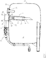
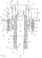
- the air and oil filter group (3) of the present invention is denoted by reference numeral (3).
- the air and oil filter group (3) is couplable to a wall (12) of an oil tank (13) at an oil inlet through-hole (22) made in the wall (12) of the oil tank (13).
- the air and oil filter group (3) comprises a housing (5) of an oil filter element (9), which: comprises an oil inlet (6); comprises an oil outlet (7); comprises a first seating (8) for receiving an oil filter element (9), which first seating (8) is arranged such that the oil coming from the oil inlet (6) can be filtered by the oil filter element (9) and be conveyed towards the oil outlet (7); comprises a first opening (10) which is dimensioned so as to enable insertion and extraction of the oil filter element (9) into and out of the first seating (8); is insertable through the inlet through-hole of the oil (22) in such a way that the oil outlet (7) is in communication with a chamber (14) of the oil tank (13).
- an oil filter element (9) which: comprises an oil inlet (6); comprises an oil outlet (7); comprises a first seating (8) for receiving an oil filter element (9), which first seating (8) is arranged such that the oil coming from the oil inlet (6) can be filtered by the oil filter element (9) and be conveyed towards the oil outlet
- the air and oil filter group (3) comprises a housing (28) of an air filter element (29), comprising: an air inlet (25); an air outlet (26); a second seating (27) for receiving an air filter element (29), which second seating (27) is arranged such that the air coming from the air inlet (25) can be filtered by the air filter element (29) and be conveyed towards the air outlet (26); a second opening (30) which is dimensioned for enabling insertion and extraction of the air filter element (29) into and out of the second seating (27).
- the air and oil filter group (3) comprises a hollow body (15) which: internally forms a chamber; is provided with a first conduit (16) which originates from the chamber (17) of the hollow body (15) and which is in communication with outside the hollow body (15); is provided with a second conduit (18) which originates from the chamber (17) of the hollow body (15) and which is in communication with outside the hollow body (15); is provided with a third conduit (19) which originates from the chamber (17) of the hollow body (15) and which is in communication with outside the hollow body (15) in order to make possible a supply of oil through the chamber (17) of the hollow body (15) and towards the first conduit (16).
- the first conduit (16) and the second conduit (18) are facing one another.
- the first conduit (16), the second conduit (18) and the chamber (17) of the hollow body (15) are dimensioned and arranged with respect to one another in such a way that the oil filter element (9) can pass respectively through the second conduit (18), the chamber (17) of the hollow body (15) and the first conduit (16), and vice versa.
- the hollow body (15) is fixable to the wall (12) of the oil tank (13) at the through-hole for introduction of the oil (22), so that the first conduit (16) is in communication with the first opening (10) of the housing (5) of the oil filter element (9) and with the oil inlet (6) of the housing (5) of the oil filter element (9) when the housing (5) of the oil filter element (9) is inserted through the through-hole for introduction of the oil (22) of the oil tank (13), making possible insertion of the oil filter element (9) in the first seating (8) of the housing (5) of the oil filter element (9) respectively through the second conduit (18), the chamber (17) of the hollow body (15) and the first conduit (16), and making possible extraction of the oil filter element (9) from the first seating (8) of the housing (5) of the oil filter element (9) respectively through the first conduit (16), the chamber (17) of the hollow body (15) and the second conduit (18).
- the hollow body (15) is provided with a fourth conduit (39) which originates from the chamber (17) of the hollow body (15) and which is in communication with outside the hollow body (15).
- the hollow body (15) and the housing (28) of the air filter element (29) are dimensioned with respect to one another so that: the housing (28) of the air filter element (29) can be inserted in and extracted from the chamber (17) of the hollow body (15) through the second conduit (18); when the housing (28) of the air filter element (29) is inserted in the chamber (17) of the hollow body (15), the housing (28) of the air filter element (29) is removably couplable to the hollow body (15) such that the air inlet (25) is in communication with the second conduit (18), the air outlet (26) is in communication with the fourth conduit (39) and the second opening (30) is in communication with the second conduit (18), enabling the air filter element (29) to be inserted in, and extracted from, the second seating (27) of the housing (28) of the air filter element (29) through the second conduit (18).
- the air and oil filter group (3) further comprises a bypass conduit (40) for placing the fourth conduit (39) in fluid communication with the chamber (14) of the oil tank (13).
- the air and oil filter group (4) is defined that comprises: the above-mentioned air and oil filter group (3); the oil filter element (9); and the air filter element (29).
- the hollow body (15) is fixable to the wall (12) of the oil tank (13) by fixing screws (38) (for example four screws).
- the housing (5) of the oil filter element can be formed as a container.
- the first opening (10) can coincide with the oil inlet (6) ( figure 6 ).
- the housing (5) of the oil filter element (9) can be borne by the hollow body (15).
- the housing (5) of the oil filter element (9) can be only partially inserted in the oil inlet through-hole (22) ( figure 6 ).
- the oil filter element (9) is tubular and is provided with a filter wall (33) and an internal chamber (34) communicating with the outside environment via a first mouth (35) and a second mouth (36).
- the second mouth (36) is connected to the oil outlet (7); the first mouth (35) is facing towards the oil inlet (6).
- the oil is filtered by passing through the filter wall (33) of the oil filter element (9).
- the air and oil filter group (4) can further comprise a by-pass valve (37) which seals the first mouth (35) and intervenes only when the oil pressure contained in the chamber (17) of the hollow body (15) exceeds a certain value, due to the reduction of the filtering capacity of the oil filter element (9): in this case the oil bypasses the filter wall (33) of the oil filter element (9) and is conveyed from the first conduit (16) of the hollow body (15) through the first mouth (35), the chamber (34) of the oil filter element (9), the second mouth (36) and the oil outlet (7).
- a by-pass valve (37) which seals the first mouth (35) and intervenes only when the oil pressure contained in the chamber (17) of the hollow body (15) exceeds a certain value, due to the reduction of the filtering capacity of the oil filter element (9): in this case the oil bypasses the filter wall (33) of the oil filter element (9) and is conveyed from the first conduit (16) of the hollow body (15) through the first mouth (35), the chamber (34) of the oil filter
- the arrows denoted by reference letter (L) indicate the pathway followed by the oil coming from the directional control valve (21) through the third conduit (19), the chamber (17) of the hollow body (15), the first conduit (16), the oil inlet (6), the oil filter element (9), the oil outlet (7) and the chamber (14) of the oil tank (13).
- the hollow body (15) and the housing (28) of the air filter element (29) are preferably reciprocally dimensioned such that the presence of the housing (28) of the air filter element (29) in the chamber (17) of the hollow body (15) does not compromise the passage of oil from the third conduit (19) to the first conduit (16).
- the housing (28) of the air filter element (29) is preferably provided with an external threading (not illustrated), and the hollow body (15) is provided with a nut screw (not illustrated) at the chamber (17) of the hollow body (15) for coupling with the external threading (41), such that the housing (28) of the air filter element (29) is screwable and unscrewable to and from the chamber (17) of the hollow body (15).
- the hollow body (15) and the housing (28) of the air filter element (29) are preferably reciprocally dimensioned such that when the housing (28) of the air filter element (29) is coupled to the hollow body (15), the housing (28) of the air filter element (29) occludes the second conduit (18); further, the air and oil filter group (3) comprises a cap (20) removably couplable to the housing (28) of the air filter element (29) so as to access the air filter element (29) when the air filter element (29) is arranged in the housing (28) of the air filter element (29).
- the housing (28) of the air filter element (29) thus prevents dirt and impurities from entering the chamber (17) of the hollow body (15), functioning as a removable closure element for the second conduit (18).
- the cap (20) and the housing (28) of the air filter element (29) can both be conformed for defining the air inlet (25); in this case the presence of the cap (20) is necessary, including in the absence of the air filter element (29).
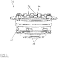
- the housing (28) of the air filter element (29) substantially has a beaker shape and comprises ( figures 4 and 5 ): a base (42), a lateral wall (43) that is substantially cylindrical and connected to the base (42); and a central portion (44) which develops internally from the base (42), faces the cylindrical lateral wall (43) and is provided with a threaded seating.
- the cap (20) centrally exhibits a threaded shank (45) for coupling with the threaded seating ( figure 6 ) and is conformed so as to abut the air filter element (29) when the air filter element (29) is arranged in the housing (28) of the air filter element (29).
- the air filter element (29) in this case has a tubular shape (see figure 6 ).
- the fourth conduit (39) is preferably identified in the bypass conduit (40) and is fashioned in the hollow body (15). As a consequence the air and oil filter group (3) is more compact.
- the invention also relates to a directional control valve group (21), comprising an air and oil filter group (3) as described in the foregoing and a directional control valve group (21).
- the directional control valve (21) is preferably fixed to the hollow body (15): in this case the body of the directional control valve (21) can be made of cast iron (by casting) for supporting the high pressures of the circulating oil, while the hollow body (15) can be made of aluminium (for example by die casting) and is therefore lighter.
- the directional control valve (21) is in a single body with the hollow body (15); in this case the body of the directional control valve (21) and the hollow body (15) can be made by a single casting, and the material they are made of is preferably cast iron.
Landscapes
- Chemical & Material Sciences (AREA)
- Chemical Kinetics & Catalysis (AREA)
- Filtering Of Dispersed Particles In Gases (AREA)
- Fluid-Pressure Circuits (AREA)
Claims (3)
- Luft- und Ölfiltergruppe (3), die an einem Durchgangsloch zum Einlassen des Öls (22), das in einer Wand (12) eines Öltanks (13) erzeugt wurde, an die Wand des Öltanks (13) koppelbar ist, wobei:die Gruppe (3) ein Gehäuse (5) eines Ölfilterelements (9) umfasst, das: einen Öleinlass (6) umfasst; einen Ölauslass (7) umfasst; einen ersten Sitz (8) zum Aufnehmen eines Ölfilterelements (9) umfasst, wobei der erste Sitz (8) derart angeordnet ist, dass das Öl aus dem Öleinlass (6) durch das Ölfilterelement (9) gefiltert und an den Ölauslass (7) geleitet werden kann; eine erste Öffnung (10) umfasst, die derart abgemessen ist, dass sie das Einführen und Herausnehmen des Ölfilterelements (9) in den ersten Sitz (8) und aus diesem heraus ermöglicht; durch das Einlassdurchgangsloch des Öls (22) derart einführbar ist, dass der Ölauslass (7) mit einer Kammer (14) des Öltanks (13) in Verbindung steht;die Gruppe (3) ein Gehäuse (28) eines Luftfilterelements (29) umfasst, umfassend: einen Lufteinlass (25); einen Luftauslass (26); einen zweiten Sitz (27) zum Aufnehmen eines Luftfilterelements (29), wobei der zweite Sitz (27) derart angeordnet ist, dass Luft aus dem Lufteinlass (25) durch da Luftfilterelement (29) gefiltert und zu dem Luftauslass (26) geleitet werden kann; eine zweite Öffnung (30), die derart abgemessen ist, dass sie das Einführen und Herausnehmen des Luftfilterelements (29) in den zweiten Sitz (27) und aus diesem heraus ermöglicht;die Gruppe (3) einen Hohlkörper (15) umfasst, der: im Inneren eine Kammer (17) bildet; mit einer ersten Leitung (16) versehen ist, die von der Kammer (17) des Hohlkörpers (15) ausgeht und mit dem Äußeren des Hohlkörpers (15) in Verbindung steht; mit einer zweiten Leitung (18) versehen ist, die von der Kammer (17) des Hohlkörpers (15) ausgeht und in Verbindung mit dem Äußeren des Hohlkörpers (15) steht; mit einer dritten Leitung (19) versehen ist, die von der Kammer (17) des Hohlkörpers (15) ausgeht und mit dem Äußeren des Hohlkörpers (15) in Verbindung steht, um eine Zufuhr von Öl durch die Kammer (17) des Hohlkörpers (15) und zur ersten Leitung (16) zu ermöglichen; die erste Leitung (16) und die zweite Leitung (18) einander zugewandt sind; die erste Leitung (16), die zweite Leitung (18) und die Kammer (17) des Hohlkörpers (15) in Bezug auf einander derart abgemessen und angeordnet sind, dass das Ölfilterelement (9) jeweils durch die zweite Leitung (18), die Kammer (17) des Hohlkörpers (15) und die erste Leitung (16) und umgekehrt treten kann;der Hohlkörper (15) an dem Durchgangsloch zum Einleiten des Öls (22) an der Wand (12) des Öltanks (13) fixierbar ist, sodass die erste Leitung (16) mit der ersten Öffnung (10) des Gehäuses (5) des Ölfilterelements (9) und mit dem Öleinlass (6) des Gehäuses (5) des Ölfilterelements (9) in Verbindung steht, wenn das Gehäuse (5) des Ölfilterelements (9) durch das Durchgangsloch zum Einleiten des Öls (22) des Öltanks (13) eingeführt ist, was das Einführen des Ölfilterelements (9) in den ersten Sitz (8) des Gehäuses (5) des Ölfilterelement (9) jeweils durch die zweite Leitung (18), die Kammer (17) des Hohlkörpers (15) und die erste Leitung (16) ermöglicht und das Herausnehmen des Ölfilterelements (9) aus dem ersten Sitz (8) des Gehäuses (5) des Ölfilterelements (9) jeweils durch die erste Leitung (16), die Kammer (17) des Hohlkörpers (15) und die zweite Leitung (18) ermöglicht;der Hohlkörper (15) mit einer vierten Leitung (39) versehen ist, die von der Kammer (17) des Hohlkörpers (15) ausgeht und mit dem Äußeren des Hohlkörpers (15) in Verbindung steht;der Hohlkörper (15) und das Gehäuse (28) des Luftfilterelements (29) in Bezug aufeinander derart abgemessen sind, dass: das Gehäuse (28) des Luftfilterelements (29) durch die zweite Leitung (18) in die Kammer (17) des Hohlkörpers (15) eingeführt und daraus herausgenommen werden kann; wenn das Gehäuse (28) des Luftfilterelements (29) in die Kammer (17) des Hohlkörpers (15) eingeführt ist, das Gehäuse (28) des Luftfilterelement (29) lösbar an den Hohlkörper (15) koppelbar ist, derart, dass der Lufteinlass (25) mit der zweiten Leitung (18) in Verbindung steht, der Luftauslass (26) mit der vierten Leitung (39) in Verbindung steht und die zweite Öffnung (30) mit der zweiten Leitung (18) in Verbindung steht, was es ermöglicht, das Luftfilterelement (29) durch die zweite Leitung (18) in den zweiten Sitz (27) des Gehäuses (28) des Luftfilterelements (29) einzuführen und daraus herauszunehmen;die Gruppe (3) eine Umgehungsleitung (40) umfasst, um die vierte Leitung (39) mit der Kammer (14) des Öltanks (13) in Fluidverbindung zu setzen; das Gehäuse (28) des Luftfilterelements (29) mit einem Außengewinde versehen ist;eine Kappe (20) umfasst, die lösbar an das Gehäuse (28) des Luftfilterelements (29) koppelbar ist, um auf das Luftfilterelement (29) zuzugreifen, wenn das Luftfilterelement (29) im Gehäuse (28) des Luftfilterelements (29) angeordnet ist;dadurch gekennzeichnet, dass:der Hohlkörper (15) mit einer Schraubmutter zum Koppeln mit dem Außengewinde an der Kammer (17) des Hohlkörpers (15) versehen ist, derart, dass das Gehäuse (28) des Luftfilterelements (29) an die Kammer (17) des Hohlkörpers (15) geschraubt und schraubend davon gelöst werden kann;der Hohlkörper (15) und das Gehäuse (28) des Luftfilterelement (29) gegenseitig derart abgemessen sind, dass, wenn das Gehäuse (28) des Luftfilterelements (29) an den Hohlkörper (15) gekoppelt ist, das Gehäuse (28) des Luftfilterelements (29) die zweite Leitung (18) versperrt.
- Gruppe nach Anspruch 1, wobei die vierte Leitung (39) in der Umgehungsleitung (40) identifiziert ist und im Hohlkörper (15) ausgebildet ist.
- Richtungssteuerungsventilgruppe (21), umfassend eine Gruppe zum Filtern von Luft und Öl nach einem der vorangehenden Ansprüche und ein Richtungssteuerungsventil (21), wobei das Richtungssteuerungsventil (21) am Hohlkörper (15) fixiert ist oder einstückig mit dem Hohlkörper (15) ist.
Applications Claiming Priority (2)
| Application Number | Priority Date | Filing Date | Title |
|---|---|---|---|
| ITBO20150015 | 2015-01-19 | ||
| PCT/IB2016/050186 WO2016116838A1 (en) | 2015-01-19 | 2016-01-15 | Air and oil filter in an oil inlet of an oil tank |
Publications (2)
| Publication Number | Publication Date |
|---|---|
| EP3247482A1 EP3247482A1 (de) | 2017-11-29 |
| EP3247482B1 true EP3247482B1 (de) | 2020-03-25 |
Family
ID=52633346
Family Applications (1)
| Application Number | Title | Priority Date | Filing Date |
|---|---|---|---|
| EP16709565.2A Active EP3247482B1 (de) | 2015-01-19 | 2016-01-15 | Luft- und ölfilter im öleinlass eines öltanks |
Country Status (4)
| Country | Link |
|---|---|
| EP (1) | EP3247482B1 (de) |
| ES (1) | ES2800300T3 (de) |
| PT (1) | PT3247482T (de) |
| WO (1) | WO2016116838A1 (de) |
Families Citing this family (2)
| Publication number | Priority date | Publication date | Assignee | Title |
|---|---|---|---|---|
| JP6839520B2 (ja) * | 2016-10-31 | 2021-03-10 | ヤマシンフィルタ株式会社 | フィルタ装置 |
| CN115949629B (zh) * | 2023-02-24 | 2025-11-21 | 成都立航科技股份有限公司 | 一种eha集成液压油箱 |
Family Cites Families (4)
| Publication number | Priority date | Publication date | Assignee | Title |
|---|---|---|---|---|
| DE4310234C1 (de) * | 1993-03-30 | 1994-08-18 | Argo Feinmechanik | Rücklauffilter für Flüssigkeiten |
| ATE232129T1 (de) * | 1995-11-10 | 2003-02-15 | Mahle Filtersysteme Gmbh | Filter für in einen geschlossenen behälter fliessende flüssigkeit |
| DE19541962A1 (de) * | 1995-11-10 | 1997-05-15 | Knecht Filterwerke Gmbh | Hydraulikfilter |
| DE102010015494A1 (de) * | 2010-04-16 | 2011-12-01 | Mahle International Gmbh | Filtereinrichtung |
-
2016
- 2016-01-15 EP EP16709565.2A patent/EP3247482B1/de active Active
- 2016-01-15 WO PCT/IB2016/050186 patent/WO2016116838A1/en not_active Ceased
- 2016-01-15 ES ES16709565T patent/ES2800300T3/es active Active
- 2016-01-15 PT PT167095652T patent/PT3247482T/pt unknown
Non-Patent Citations (1)
| Title |
|---|
| None * |
Also Published As
| Publication number | Publication date |
|---|---|
| PT3247482T (pt) | 2020-05-21 |
| WO2016116838A1 (en) | 2016-07-28 |
| ES2800300T3 (es) | 2020-12-29 |
| EP3247482A1 (de) | 2017-11-29 |
Similar Documents
| Publication | Publication Date | Title |
|---|---|---|
| DE10309428B4 (de) | Filter | |
| EP3449995B1 (de) | Schlammfiltervorrichtung | |
| EP0534672B1 (de) | Filtereinheit | |
| WO2012104185A1 (de) | Filtersystem für motoröl einer brennkraftmaschine und wechselfilter eines filtersystems | |
| DE102015003165A1 (de) | Kraftstofffilter mit einem Kraftstofffiltereinsatz mit einem Vor- und einem Hauptfilterelement | |
| DE202011104284U1 (de) | Luft- und Schmutzabscheider mit Elastomermembran-Entlüfter | |
| DE102010032394A1 (de) | Luft- und Schmutzabscheider für die Wassertechnik | |
| EP3247482A1 (de) | Luft- und ölfilter in einem öleinlass eines öltanks | |
| CN208518659U (zh) | 一种除砂效率高的除砂器 | |
| CN206860966U (zh) | 一种防堵塞阀门 | |
| CN107349667A (zh) | 一种阀门用过滤装置 | |
| CN102648034A (zh) | 压力过滤装置 | |
| CN106838349A (zh) | 一种过滤阀 | |
| DE102012012727A1 (de) | Vorrichtung zur Konditionierung von Gasen | |
| CN201058253Y (zh) | 过滤器水道结构 | |
| CN209405854U (zh) | 一种离心机过滤器防堵塞的冲洗装置 | |
| CN208327431U (zh) | 一种净水装置 | |
| CN208474923U (zh) | 一种润滑油过滤器 | |
| CN108040838A (zh) | 用于自动灌溉的智能恒压器 | |
| CN205331668U (zh) | 一种改进的油路分配器 | |
| CN208634450U (zh) | 一种方便更换过滤网的止回阀 | |
| CN204779213U (zh) | 一种永磁复合过滤设备 | |
| CN109091945A (zh) | 一种快速拆换净水器 | |
| CN107366660A (zh) | 一种带旁通的液压油过滤器 | |
| CN207561043U (zh) | 用于自动灌溉的智能恒压器 |
Legal Events
| Date | Code | Title | Description |
|---|---|---|---|
| STAA | Information on the status of an ep patent application or granted ep patent |
Free format text: STATUS: THE INTERNATIONAL PUBLICATION HAS BEEN MADE |
|
| PUAI | Public reference made under article 153(3) epc to a published international application that has entered the european phase |
Free format text: ORIGINAL CODE: 0009012 |
|
| STAA | Information on the status of an ep patent application or granted ep patent |
Free format text: STATUS: REQUEST FOR EXAMINATION WAS MADE |
|
| 17P | Request for examination filed |
Effective date: 20170802 |
|
| AK | Designated contracting states |
Kind code of ref document: A1 Designated state(s): AL AT BE BG CH CY CZ DE DK EE ES FI FR GB GR HR HU IE IS IT LI LT LU LV MC MK MT NL NO PL PT RO RS SE SI SK SM TR |
|
| AX | Request for extension of the european patent |
Extension state: BA ME |
|
| DAV | Request for validation of the european patent (deleted) | ||
| DAX | Request for extension of the european patent (deleted) | ||
| GRAP | Despatch of communication of intention to grant a patent |
Free format text: ORIGINAL CODE: EPIDOSNIGR1 |
|
| STAA | Information on the status of an ep patent application or granted ep patent |
Free format text: STATUS: GRANT OF PATENT IS INTENDED |
|
| INTG | Intention to grant announced |
Effective date: 20191016 |
|
| GRAS | Grant fee paid |
Free format text: ORIGINAL CODE: EPIDOSNIGR3 |
|
| GRAA | (expected) grant |
Free format text: ORIGINAL CODE: 0009210 |
|
| STAA | Information on the status of an ep patent application or granted ep patent |
Free format text: STATUS: THE PATENT HAS BEEN GRANTED |
|
| AK | Designated contracting states |
Kind code of ref document: B1 Designated state(s): AL AT BE BG CH CY CZ DE DK EE ES FI FR GB GR HR HU IE IS IT LI LT LU LV MC MK MT NL NO PL PT RO RS SE SI SK SM TR |
|
| REG | Reference to a national code |
Ref country code: GB Ref legal event code: FG4D |
|
| REG | Reference to a national code |
Ref country code: AT Ref legal event code: REF Ref document number: 1247907 Country of ref document: AT Kind code of ref document: T Effective date: 20200415 Ref country code: IE Ref legal event code: FG4D |
|
| REG | Reference to a national code |
Ref country code: DE Ref legal event code: R096 Ref document number: 602016032479 Country of ref document: DE |
|
| REG | Reference to a national code |
Ref country code: PT Ref legal event code: SC4A Ref document number: 3247482 Country of ref document: PT Date of ref document: 20200521 Kind code of ref document: T Free format text: AVAILABILITY OF NATIONAL TRANSLATION Effective date: 20200514 |
|
| PG25 | Lapsed in a contracting state [announced via postgrant information from national office to epo] |
Ref country code: RS Free format text: LAPSE BECAUSE OF FAILURE TO SUBMIT A TRANSLATION OF THE DESCRIPTION OR TO PAY THE FEE WITHIN THE PRESCRIBED TIME-LIMIT Effective date: 20200325 Ref country code: NO Free format text: LAPSE BECAUSE OF FAILURE TO SUBMIT A TRANSLATION OF THE DESCRIPTION OR TO PAY THE FEE WITHIN THE PRESCRIBED TIME-LIMIT Effective date: 20200625 Ref country code: FI Free format text: LAPSE BECAUSE OF FAILURE TO SUBMIT A TRANSLATION OF THE DESCRIPTION OR TO PAY THE FEE WITHIN THE PRESCRIBED TIME-LIMIT Effective date: 20200325 |
|
| PG25 | Lapsed in a contracting state [announced via postgrant information from national office to epo] |
Ref country code: LV Free format text: LAPSE BECAUSE OF FAILURE TO SUBMIT A TRANSLATION OF THE DESCRIPTION OR TO PAY THE FEE WITHIN THE PRESCRIBED TIME-LIMIT Effective date: 20200325 Ref country code: SE Free format text: LAPSE BECAUSE OF FAILURE TO SUBMIT A TRANSLATION OF THE DESCRIPTION OR TO PAY THE FEE WITHIN THE PRESCRIBED TIME-LIMIT Effective date: 20200325 Ref country code: HR Free format text: LAPSE BECAUSE OF FAILURE TO SUBMIT A TRANSLATION OF THE DESCRIPTION OR TO PAY THE FEE WITHIN THE PRESCRIBED TIME-LIMIT Effective date: 20200325 Ref country code: GR Free format text: LAPSE BECAUSE OF FAILURE TO SUBMIT A TRANSLATION OF THE DESCRIPTION OR TO PAY THE FEE WITHIN THE PRESCRIBED TIME-LIMIT Effective date: 20200626 Ref country code: BG Free format text: LAPSE BECAUSE OF FAILURE TO SUBMIT A TRANSLATION OF THE DESCRIPTION OR TO PAY THE FEE WITHIN THE PRESCRIBED TIME-LIMIT Effective date: 20200625 |
|
| REG | Reference to a national code |
Ref country code: NL Ref legal event code: MP Effective date: 20200325 |
|
| REG | Reference to a national code |
Ref country code: LT Ref legal event code: MG4D |
|
| PG25 | Lapsed in a contracting state [announced via postgrant information from national office to epo] |
Ref country code: NL Free format text: LAPSE BECAUSE OF FAILURE TO SUBMIT A TRANSLATION OF THE DESCRIPTION OR TO PAY THE FEE WITHIN THE PRESCRIBED TIME-LIMIT Effective date: 20200325 |
|
| PG25 | Lapsed in a contracting state [announced via postgrant information from national office to epo] |
Ref country code: SM Free format text: LAPSE BECAUSE OF FAILURE TO SUBMIT A TRANSLATION OF THE DESCRIPTION OR TO PAY THE FEE WITHIN THE PRESCRIBED TIME-LIMIT Effective date: 20200325 Ref country code: EE Free format text: LAPSE BECAUSE OF FAILURE TO SUBMIT A TRANSLATION OF THE DESCRIPTION OR TO PAY THE FEE WITHIN THE PRESCRIBED TIME-LIMIT Effective date: 20200325 Ref country code: RO Free format text: LAPSE BECAUSE OF FAILURE TO SUBMIT A TRANSLATION OF THE DESCRIPTION OR TO PAY THE FEE WITHIN THE PRESCRIBED TIME-LIMIT Effective date: 20200325 Ref country code: SK Free format text: LAPSE BECAUSE OF FAILURE TO SUBMIT A TRANSLATION OF THE DESCRIPTION OR TO PAY THE FEE WITHIN THE PRESCRIBED TIME-LIMIT Effective date: 20200325 Ref country code: LT Free format text: LAPSE BECAUSE OF FAILURE TO SUBMIT A TRANSLATION OF THE DESCRIPTION OR TO PAY THE FEE WITHIN THE PRESCRIBED TIME-LIMIT Effective date: 20200325 Ref country code: IS Free format text: LAPSE BECAUSE OF FAILURE TO SUBMIT A TRANSLATION OF THE DESCRIPTION OR TO PAY THE FEE WITHIN THE PRESCRIBED TIME-LIMIT Effective date: 20200725 Ref country code: CZ Free format text: LAPSE BECAUSE OF FAILURE TO SUBMIT A TRANSLATION OF THE DESCRIPTION OR TO PAY THE FEE WITHIN THE PRESCRIBED TIME-LIMIT Effective date: 20200325 |
|
| REG | Reference to a national code |
Ref country code: AT Ref legal event code: MK05 Ref document number: 1247907 Country of ref document: AT Kind code of ref document: T Effective date: 20200325 |
|
| REG | Reference to a national code |
Ref country code: DE Ref legal event code: R097 Ref document number: 602016032479 Country of ref document: DE |
|
| PG25 | Lapsed in a contracting state [announced via postgrant information from national office to epo] |
Ref country code: AT Free format text: LAPSE BECAUSE OF FAILURE TO SUBMIT A TRANSLATION OF THE DESCRIPTION OR TO PAY THE FEE WITHIN THE PRESCRIBED TIME-LIMIT Effective date: 20200325 Ref country code: DK Free format text: LAPSE BECAUSE OF FAILURE TO SUBMIT A TRANSLATION OF THE DESCRIPTION OR TO PAY THE FEE WITHIN THE PRESCRIBED TIME-LIMIT Effective date: 20200325 |
|
| PLBE | No opposition filed within time limit |
Free format text: ORIGINAL CODE: 0009261 |
|
| STAA | Information on the status of an ep patent application or granted ep patent |
Free format text: STATUS: NO OPPOSITION FILED WITHIN TIME LIMIT |
|
| PG25 | Lapsed in a contracting state [announced via postgrant information from national office to epo] |
Ref country code: PL Free format text: LAPSE BECAUSE OF FAILURE TO SUBMIT A TRANSLATION OF THE DESCRIPTION OR TO PAY THE FEE WITHIN THE PRESCRIBED TIME-LIMIT Effective date: 20200325 |
|
| 26N | No opposition filed |
Effective date: 20210112 |
|
| PG25 | Lapsed in a contracting state [announced via postgrant information from national office to epo] |
Ref country code: SI Free format text: LAPSE BECAUSE OF FAILURE TO SUBMIT A TRANSLATION OF THE DESCRIPTION OR TO PAY THE FEE WITHIN THE PRESCRIBED TIME-LIMIT Effective date: 20200325 |
|
| PG25 | Lapsed in a contracting state [announced via postgrant information from national office to epo] |
Ref country code: MC Free format text: LAPSE BECAUSE OF FAILURE TO SUBMIT A TRANSLATION OF THE DESCRIPTION OR TO PAY THE FEE WITHIN THE PRESCRIBED TIME-LIMIT Effective date: 20200325 |
|
| REG | Reference to a national code |
Ref country code: CH Ref legal event code: PL |
|
| GBPC | Gb: european patent ceased through non-payment of renewal fee |
Effective date: 20210115 |
|
| PG25 | Lapsed in a contracting state [announced via postgrant information from national office to epo] |
Ref country code: LU Free format text: LAPSE BECAUSE OF NON-PAYMENT OF DUE FEES Effective date: 20210115 |
|
| REG | Reference to a national code |
Ref country code: BE Ref legal event code: MM Effective date: 20210131 |
|
| PG25 | Lapsed in a contracting state [announced via postgrant information from national office to epo] |
Ref country code: GB Free format text: LAPSE BECAUSE OF NON-PAYMENT OF DUE FEES Effective date: 20210115 Ref country code: CH Free format text: LAPSE BECAUSE OF NON-PAYMENT OF DUE FEES Effective date: 20210131 Ref country code: LI Free format text: LAPSE BECAUSE OF NON-PAYMENT OF DUE FEES Effective date: 20210131 |
|
| PG25 | Lapsed in a contracting state [announced via postgrant information from national office to epo] |
Ref country code: IE Free format text: LAPSE BECAUSE OF NON-PAYMENT OF DUE FEES Effective date: 20210115 |
|
| PG25 | Lapsed in a contracting state [announced via postgrant information from national office to epo] |
Ref country code: BE Free format text: LAPSE BECAUSE OF NON-PAYMENT OF DUE FEES Effective date: 20210131 |
|
| PG25 | Lapsed in a contracting state [announced via postgrant information from national office to epo] |
Ref country code: HU Free format text: LAPSE BECAUSE OF FAILURE TO SUBMIT A TRANSLATION OF THE DESCRIPTION OR TO PAY THE FEE WITHIN THE PRESCRIBED TIME-LIMIT; INVALID AB INITIO Effective date: 20160115 |
|
| P01 | Opt-out of the competence of the unified patent court (upc) registered |
Effective date: 20230313 |
|
| PG25 | Lapsed in a contracting state [announced via postgrant information from national office to epo] |
Ref country code: CY Free format text: LAPSE BECAUSE OF FAILURE TO SUBMIT A TRANSLATION OF THE DESCRIPTION OR TO PAY THE FEE WITHIN THE PRESCRIBED TIME-LIMIT Effective date: 20200325 |
|
| PG25 | Lapsed in a contracting state [announced via postgrant information from national office to epo] |
Ref country code: MK Free format text: LAPSE BECAUSE OF FAILURE TO SUBMIT A TRANSLATION OF THE DESCRIPTION OR TO PAY THE FEE WITHIN THE PRESCRIBED TIME-LIMIT Effective date: 20200325 |
|
| PG25 | Lapsed in a contracting state [announced via postgrant information from national office to epo] |
Ref country code: MT Free format text: LAPSE BECAUSE OF FAILURE TO SUBMIT A TRANSLATION OF THE DESCRIPTION OR TO PAY THE FEE WITHIN THE PRESCRIBED TIME-LIMIT Effective date: 20200325 |
|
| PG25 | Lapsed in a contracting state [announced via postgrant information from national office to epo] |
Ref country code: TR Free format text: LAPSE BECAUSE OF FAILURE TO SUBMIT A TRANSLATION OF THE DESCRIPTION OR TO PAY THE FEE WITHIN THE PRESCRIBED TIME-LIMIT Effective date: 20200325 |
|
| PGFP | Annual fee paid to national office [announced via postgrant information from national office to epo] |
Ref country code: PT Payment date: 20251202 Year of fee payment: 11 |
|
| PGFP | Annual fee paid to national office [announced via postgrant information from national office to epo] |
Ref country code: ES Payment date: 20260210 Year of fee payment: 11 |
|
| PGFP | Annual fee paid to national office [announced via postgrant information from national office to epo] |
Ref country code: DE Payment date: 20260223 Year of fee payment: 11 |
|
| PGFP | Annual fee paid to national office [announced via postgrant information from national office to epo] |
Ref country code: IT Payment date: 20260130 Year of fee payment: 11 |
|
| PGFP | Annual fee paid to national office [announced via postgrant information from national office to epo] |
Ref country code: FR Payment date: 20260122 Year of fee payment: 11 |