EP3247479B1 - Verfahren zum trennen von wasser und öl mit stauchrohren zur verdampfung von wasser - Google Patents
Verfahren zum trennen von wasser und öl mit stauchrohren zur verdampfung von wasser Download PDFInfo
- Publication number
- EP3247479B1 EP3247479B1 EP15710270.8A EP15710270A EP3247479B1 EP 3247479 B1 EP3247479 B1 EP 3247479B1 EP 15710270 A EP15710270 A EP 15710270A EP 3247479 B1 EP3247479 B1 EP 3247479B1
- Authority
- EP
- European Patent Office
- Prior art keywords
- yarn
- oil
- filter
- evaporation chamber
- core
- Prior art date
- Legal status (The legal status is an assumption and is not a legal conclusion. Google has not performed a legal analysis and makes no representation as to the accuracy of the status listed.)
- Not-in-force
Links
- XLYOFNOQVPJJNP-UHFFFAOYSA-N water Substances O XLYOFNOQVPJJNP-UHFFFAOYSA-N 0.000 title claims description 63
- 238000000926 separation method Methods 0.000 title description 8
- 238000004804 winding Methods 0.000 claims description 120
- 238000001704 evaporation Methods 0.000 claims description 74
- 230000008020 evaporation Effects 0.000 claims description 74
- 238000000034 method Methods 0.000 claims description 43
- 239000000835 fiber Substances 0.000 claims description 29
- 238000001914 filtration Methods 0.000 claims description 26
- 239000012530 fluid Substances 0.000 claims description 26
- 239000011261 inert gas Substances 0.000 claims description 20
- 238000004821 distillation Methods 0.000 claims description 19
- 229920002994 synthetic fiber Polymers 0.000 claims description 18
- 239000012209 synthetic fiber Substances 0.000 claims description 16
- 238000007664 blowing Methods 0.000 claims description 14
- 239000004952 Polyamide Substances 0.000 claims description 12
- 229920002647 polyamide Polymers 0.000 claims description 12
- 239000000203 mixture Substances 0.000 claims description 11
- -1 acryl Chemical group 0.000 claims description 10
- 241000208202 Linaceae Species 0.000 claims description 9
- 235000004431 Linum usitatissimum Nutrition 0.000 claims description 9
- 229920000728 polyester Polymers 0.000 claims description 9
- 229920000742 Cotton Polymers 0.000 claims description 7
- 229920000297 Rayon Polymers 0.000 claims description 7
- 239000007792 gaseous phase Substances 0.000 claims description 7
- 238000004891 communication Methods 0.000 claims description 6
- 239000000463 material Substances 0.000 claims description 6
- 210000002268 wool Anatomy 0.000 claims description 6
- QTBSBXVTEAMEQO-UHFFFAOYSA-M Acetate Chemical compound CC([O-])=O QTBSBXVTEAMEQO-UHFFFAOYSA-M 0.000 claims description 5
- 229910052751 metal Inorganic materials 0.000 claims description 5
- 239000002184 metal Substances 0.000 claims description 5
- 239000004411 aluminium Substances 0.000 claims description 4
- 229910052782 aluminium Inorganic materials 0.000 claims description 4
- XAGFODPZIPBFFR-UHFFFAOYSA-N aluminium Chemical compound [Al] XAGFODPZIPBFFR-UHFFFAOYSA-N 0.000 claims description 4
- 239000007791 liquid phase Substances 0.000 claims description 4
- 229910001092 metal group alloy Inorganic materials 0.000 claims description 3
- 239000003921 oil Substances 0.000 description 128
- 230000006835 compression Effects 0.000 description 27
- 238000007906 compression Methods 0.000 description 27
- 239000002245 particle Substances 0.000 description 25
- 239000000356 contaminant Substances 0.000 description 21
- 239000007788 liquid Substances 0.000 description 11
- 230000005540 biological transmission Effects 0.000 description 8
- 239000010687 lubricating oil Substances 0.000 description 8
- 239000007787 solid Substances 0.000 description 7
- 230000033001 locomotion Effects 0.000 description 6
- 238000004519 manufacturing process Methods 0.000 description 5
- 239000002253 acid Substances 0.000 description 4
- 150000007513 acids Chemical class 0.000 description 4
- 230000008901 benefit Effects 0.000 description 4
- 238000010586 diagram Methods 0.000 description 4
- 239000004753 textile Substances 0.000 description 4
- 238000002485 combustion reaction Methods 0.000 description 3
- 239000000446 fuel Substances 0.000 description 3
- 239000007789 gas Substances 0.000 description 3
- 238000010438 heat treatment Methods 0.000 description 3
- 238000011835 investigation Methods 0.000 description 3
- 238000005461 lubrication Methods 0.000 description 3
- 239000010705 motor oil Substances 0.000 description 3
- 230000008859 change Effects 0.000 description 2
- 238000004140 cleaning Methods 0.000 description 2
- 238000009833 condensation Methods 0.000 description 2
- 230000005494 condensation Effects 0.000 description 2
- 230000001419 dependent effect Effects 0.000 description 2
- 239000010720 hydraulic oil Substances 0.000 description 2
- 230000002209 hydrophobic effect Effects 0.000 description 2
- 230000006872 improvement Effects 0.000 description 2
- 238000009434 installation Methods 0.000 description 2
- 230000009257 reactivity Effects 0.000 description 2
- 238000009423 ventilation Methods 0.000 description 2
- OKTJSMMVPCPJKN-UHFFFAOYSA-N Carbon Chemical compound [C] OKTJSMMVPCPJKN-UHFFFAOYSA-N 0.000 description 1
- 230000001580 bacterial effect Effects 0.000 description 1
- 238000009835 boiling Methods 0.000 description 1
- 229910052799 carbon Inorganic materials 0.000 description 1
- 238000011109 contamination Methods 0.000 description 1
- 238000005520 cutting process Methods 0.000 description 1
- 230000006866 deterioration Effects 0.000 description 1
- 230000000694 effects Effects 0.000 description 1
- 238000011068 loading method Methods 0.000 description 1
- 230000007246 mechanism Effects 0.000 description 1
- 239000002923 metal particle Substances 0.000 description 1
- 238000004064 recycling Methods 0.000 description 1
- 239000004071 soot Substances 0.000 description 1
- 238000013022 venting Methods 0.000 description 1
Images



Classifications
-
- B—PERFORMING OPERATIONS; TRANSPORTING
- B01—PHYSICAL OR CHEMICAL PROCESSES OR APPARATUS IN GENERAL
- B01D—SEPARATION
- B01D36/00—Filter circuits or combinations of filters with other separating devices
- B01D36/003—Filters in combination with devices for the removal of liquids
-
- B—PERFORMING OPERATIONS; TRANSPORTING
- B01—PHYSICAL OR CHEMICAL PROCESSES OR APPARATUS IN GENERAL
- B01D—SEPARATION
- B01D1/00—Evaporating
- B01D1/16—Evaporating by spraying
-
- B—PERFORMING OPERATIONS; TRANSPORTING
- B01—PHYSICAL OR CHEMICAL PROCESSES OR APPARATUS IN GENERAL
- B01D—SEPARATION
- B01D1/00—Evaporating
- B01D1/16—Evaporating by spraying
- B01D1/20—Sprayers
-
- B—PERFORMING OPERATIONS; TRANSPORTING
- B01—PHYSICAL OR CHEMICAL PROCESSES OR APPARATUS IN GENERAL
- B01D—SEPARATION
- B01D17/00—Separation of liquids, not provided for elsewhere, e.g. by thermal diffusion
- B01D17/02—Separation of non-miscible liquids
- B01D17/04—Breaking emulsions
- B01D17/042—Breaking emulsions by changing the temperature
-
- B—PERFORMING OPERATIONS; TRANSPORTING
- B01—PHYSICAL OR CHEMICAL PROCESSES OR APPARATUS IN GENERAL
- B01D—SEPARATION
- B01D17/00—Separation of liquids, not provided for elsewhere, e.g. by thermal diffusion
- B01D17/02—Separation of non-miscible liquids
- B01D17/04—Breaking emulsions
- B01D17/044—Breaking emulsions by changing the pressure
-
- B—PERFORMING OPERATIONS; TRANSPORTING
- B01—PHYSICAL OR CHEMICAL PROCESSES OR APPARATUS IN GENERAL
- B01D—SEPARATION
- B01D29/00—Filters with filtering elements stationary during filtration, e.g. pressure or suction filters, not covered by groups B01D24/00 - B01D27/00; Filtering elements therefor
- B01D29/88—Filters with filtering elements stationary during filtration, e.g. pressure or suction filters, not covered by groups B01D24/00 - B01D27/00; Filtering elements therefor having feed or discharge devices
- B01D29/90—Filters with filtering elements stationary during filtration, e.g. pressure or suction filters, not covered by groups B01D24/00 - B01D27/00; Filtering elements therefor having feed or discharge devices for feeding
- B01D29/906—Special treatment of the feed stream before contacting the filtering element, e.g. cutting
-
- B—PERFORMING OPERATIONS; TRANSPORTING
- B01—PHYSICAL OR CHEMICAL PROCESSES OR APPARATUS IN GENERAL
- B01D—SEPARATION
- B01D35/00—Filtering devices having features not specifically covered by groups B01D24/00 - B01D33/00, or for applications not specifically covered by groups B01D24/00 - B01D33/00; Auxiliary devices for filtration; Filter housing constructions
- B01D35/005—Filters specially adapted for use in internal-combustion engine lubrication or fuel systems
-
- C—CHEMISTRY; METALLURGY
- C10—PETROLEUM, GAS OR COKE INDUSTRIES; TECHNICAL GASES CONTAINING CARBON MONOXIDE; FUELS; LUBRICANTS; PEAT
- C10G—CRACKING HYDROCARBON OILS; PRODUCTION OF LIQUID HYDROCARBON MIXTURES, e.g. BY DESTRUCTIVE HYDROGENATION, OLIGOMERISATION, POLYMERISATION; RECOVERY OF HYDROCARBON OILS FROM OIL-SHALE, OIL-SAND, OR GASES; REFINING MIXTURES MAINLY CONSISTING OF HYDROCARBONS; REFORMING OF NAPHTHA; MINERAL WAXES
- C10G31/00—Refining of hydrocarbon oils, in the absence of hydrogen, by methods not otherwise provided for
- C10G31/06—Refining of hydrocarbon oils, in the absence of hydrogen, by methods not otherwise provided for by heating, cooling, or pressure treatment
-
- C—CHEMISTRY; METALLURGY
- C10—PETROLEUM, GAS OR COKE INDUSTRIES; TECHNICAL GASES CONTAINING CARBON MONOXIDE; FUELS; LUBRICANTS; PEAT
- C10G—CRACKING HYDROCARBON OILS; PRODUCTION OF LIQUID HYDROCARBON MIXTURES, e.g. BY DESTRUCTIVE HYDROGENATION, OLIGOMERISATION, POLYMERISATION; RECOVERY OF HYDROCARBON OILS FROM OIL-SHALE, OIL-SAND, OR GASES; REFINING MIXTURES MAINLY CONSISTING OF HYDROCARBONS; REFORMING OF NAPHTHA; MINERAL WAXES
- C10G31/00—Refining of hydrocarbon oils, in the absence of hydrogen, by methods not otherwise provided for
- C10G31/09—Refining of hydrocarbon oils, in the absence of hydrogen, by methods not otherwise provided for by filtration
-
- C—CHEMISTRY; METALLURGY
- C10—PETROLEUM, GAS OR COKE INDUSTRIES; TECHNICAL GASES CONTAINING CARBON MONOXIDE; FUELS; LUBRICANTS; PEAT
- C10G—CRACKING HYDROCARBON OILS; PRODUCTION OF LIQUID HYDROCARBON MIXTURES, e.g. BY DESTRUCTIVE HYDROGENATION, OLIGOMERISATION, POLYMERISATION; RECOVERY OF HYDROCARBON OILS FROM OIL-SHALE, OIL-SAND, OR GASES; REFINING MIXTURES MAINLY CONSISTING OF HYDROCARBONS; REFORMING OF NAPHTHA; MINERAL WAXES
- C10G33/00—Dewatering or demulsification of hydrocarbon oils
- C10G33/06—Dewatering or demulsification of hydrocarbon oils with mechanical means, e.g. by filtration
-
- B—PERFORMING OPERATIONS; TRANSPORTING
- B01—PHYSICAL OR CHEMICAL PROCESSES OR APPARATUS IN GENERAL
- B01D—SEPARATION
- B01D29/00—Filters with filtering elements stationary during filtration, e.g. pressure or suction filters, not covered by groups B01D24/00 - B01D27/00; Filtering elements therefor
- B01D29/11—Filters with filtering elements stationary during filtration, e.g. pressure or suction filters, not covered by groups B01D24/00 - B01D27/00; Filtering elements therefor with bag, cage, hose, tube, sleeve or like filtering elements
- B01D29/111—Making filtering elements
-
- C—CHEMISTRY; METALLURGY
- C10—PETROLEUM, GAS OR COKE INDUSTRIES; TECHNICAL GASES CONTAINING CARBON MONOXIDE; FUELS; LUBRICANTS; PEAT
- C10G—CRACKING HYDROCARBON OILS; PRODUCTION OF LIQUID HYDROCARBON MIXTURES, e.g. BY DESTRUCTIVE HYDROGENATION, OLIGOMERISATION, POLYMERISATION; RECOVERY OF HYDROCARBON OILS FROM OIL-SHALE, OIL-SAND, OR GASES; REFINING MIXTURES MAINLY CONSISTING OF HYDROCARBONS; REFORMING OF NAPHTHA; MINERAL WAXES
- C10G2300/00—Aspects relating to hydrocarbon processing covered by groups C10G1/00 - C10G99/00
- C10G2300/10—Feedstock materials
- C10G2300/1033—Oil well production fluids
-
- C—CHEMISTRY; METALLURGY
- C10—PETROLEUM, GAS OR COKE INDUSTRIES; TECHNICAL GASES CONTAINING CARBON MONOXIDE; FUELS; LUBRICANTS; PEAT
- C10G—CRACKING HYDROCARBON OILS; PRODUCTION OF LIQUID HYDROCARBON MIXTURES, e.g. BY DESTRUCTIVE HYDROGENATION, OLIGOMERISATION, POLYMERISATION; RECOVERY OF HYDROCARBON OILS FROM OIL-SHALE, OIL-SAND, OR GASES; REFINING MIXTURES MAINLY CONSISTING OF HYDROCARBONS; REFORMING OF NAPHTHA; MINERAL WAXES
- C10G2300/00—Aspects relating to hydrocarbon processing covered by groups C10G1/00 - C10G99/00
- C10G2300/10—Feedstock materials
- C10G2300/1037—Hydrocarbon fractions
- C10G2300/1062—Lubricating oils
-
- C—CHEMISTRY; METALLURGY
- C10—PETROLEUM, GAS OR COKE INDUSTRIES; TECHNICAL GASES CONTAINING CARBON MONOXIDE; FUELS; LUBRICANTS; PEAT
- C10G—CRACKING HYDROCARBON OILS; PRODUCTION OF LIQUID HYDROCARBON MIXTURES, e.g. BY DESTRUCTIVE HYDROGENATION, OLIGOMERISATION, POLYMERISATION; RECOVERY OF HYDROCARBON OILS FROM OIL-SHALE, OIL-SAND, OR GASES; REFINING MIXTURES MAINLY CONSISTING OF HYDROCARBONS; REFORMING OF NAPHTHA; MINERAL WAXES
- C10G2300/00—Aspects relating to hydrocarbon processing covered by groups C10G1/00 - C10G99/00
- C10G2300/20—Characteristics of the feedstock or the products
- C10G2300/201—Impurities
- C10G2300/208—Sediments, e.g. bottom sediment and water or BSW
-
- C—CHEMISTRY; METALLURGY
- C10—PETROLEUM, GAS OR COKE INDUSTRIES; TECHNICAL GASES CONTAINING CARBON MONOXIDE; FUELS; LUBRICANTS; PEAT
- C10G—CRACKING HYDROCARBON OILS; PRODUCTION OF LIQUID HYDROCARBON MIXTURES, e.g. BY DESTRUCTIVE HYDROGENATION, OLIGOMERISATION, POLYMERISATION; RECOVERY OF HYDROCARBON OILS FROM OIL-SHALE, OIL-SAND, OR GASES; REFINING MIXTURES MAINLY CONSISTING OF HYDROCARBONS; REFORMING OF NAPHTHA; MINERAL WAXES
- C10G2400/00—Products obtained by processes covered by groups C10G9/00 - C10G69/14
- C10G2400/10—Lubricating oil
Definitions
- the present invention pertains to a method and apparatus for removing water from oil.
- the present invention furthermore pertains to a method and apparatus for removing water from oil in combination with a tubular filter for filtering solid particles from said oil and a method of manufacturing said filter and a method of filtering oil.
- WO 2012/164348 A1 (Kristiansen, Ingolf ) relates to a method and an apparatus for removing alien fluids from a petrochemical product.
- Pre-heated oil is atomized, i.e. transformed into tiny droplets when passing nozzles, and the droplets are drawn out by vacuum in a ventilation chamber.
- a problem with this solution is the large power requirement.
- US 5 630 912 A (Lefebvre, Byron ) relates to an oil reclamation device with evaporation base and head mounted filter. Pre-heated oil is fed onto a heated surface to evaporate unwanted liquids from the oil. The unwanted liquids are then vented out of the evaporation chamber. A problem with this solution is the large power requirement.
- This filter alleviates some of the problems associated with the other types of filters mentioned above and known in the art.
- a first aspect of the invention pertaining to a filter for the removal of water from oil
- the filter comprising a distillation element having an inlet pipe that in one end is to be fluidly connectable to a reservoir of oil to be filtered, and in the other end being fluidly connected to a distillation head, said distillation head comprising a plurality of compression tubes for compressing said oil into an evaporation chamber, whereby eventual water within the oil evaporates from the said oil
- the filter further comprising a tubular core with a plurality of apertures and a hollow interior, said core having an open end for fluid communication with the hollow interior, a length of yarn wound around an outer surface of the core, wherein the filter further comprises means for blowing air or an inert gas into the evaporation chamber for removal of the water vapor during use of the filter.
- the oil By providing a plurality of compression tubes for injecting the oil into the evaporation chamber, the oil is compressed as a liquid into the evaporation chamber. Due to the different thermodynamic properties of the oil and the water, they react differently to changes in heat and pressure. These vaporized contaminants (steam) is then blown out of the evaporation chamber by the air or inert gas, which is blown into the evaporation chamber, while the oil is drained out in liquid form.
- a plurality of compression tubes is used in order to ensure an adequate flow rate, and the actual number of compression tubes needed may be chosen in dependence of the particular application of the inventive filter and oil types.
- said means for blowing air or an inert gas into the evaporation chamber is for example a fan that is in fluid communication with said evaporation chamber via a pipe.
- the evaporation chamber comprises an outlet for the air or inert gas, which during use is blown into the evaporation chamber.
- the compression tubes are made from a metal or metal alloy comprising aluminium, which has good heat conductivity and low reactivity with oil.
- the compression tubes have barrel sizes that are smaller than 7 mm, preferably smaller than 3 mm or between 0.5 mm and 7 mm, preferably between 0.5 mm and 3 mm, more preferably between 0.7 and 1.2 mm. Separation is achieved by selecting a barrel size that creates a significant pressure differential across the opening.
- the viscosity of different oils is largely dependent of temperature, so the barrel sizes are preferably chosen in dependence of the temperature increase the oil undergoes during friction with the barrels, and the type of oil to be filtered. To this end the applicant estimates that by using barrel sizes as mentioned above it would be possible to separate water from most types of oils.
- the compression tube have preferably a barrel that is rifled in order to thereby impart a rotational motion to the compressed injected oil and thereby enhance the separation (evaporation) of contaminants from them.
- the length of the barrel of each of the compression tubes is between 4 mm and 40 mm.
- the evaporation chamber has a sloped floor with an oil drain that during use is configured to be situated at the lowest place of the floor.
- an oil drain that during use is configured to be situated at the lowest place of the floor.
- the oil - relieved form most of the water contaminants - may be drained from the bottom of the evaporation chamber, while the gaseous phase, water steam, is removed from an upper part of the evaporation chamber by blowing in an inert gas or air.
- the terms “lower” and “upper” refers to the lower and upper parts of the evaporation chamber, when the filter is installed in its correct use position.
- the oil is pressurized, e.g. to a pressure of between 8 bars and 40 bars, before it injected through the compressing tubes.
- the evaporation chamber has a sloped floor with an oil drain that during use is configured to be situated at the lowest place of the floor.
- an oil drain that during use is configured to be situated at the lowest place of the floor.
- the oil - relieved form most of the water contaminants - may be drained from the bottom of the evaporation chamber, while the gaseous phase, water steam, is removed from an upper part of the evaporation chamber by blowing in an inert gas or air.
- the terms “lower” and “upper” refers to the lower and upper parts of the evaporation chamber, when the filter is installed in its correct use position.
- the oil is pressurized, e.g. to a pressure of between 10 bar and 20 bar, before it is compressed through the compression tubes.
- the yarn is wound in a series of at least 4 layers around the outer surface of the core, wherein the first layer closest to the surface of the core comprises at least 15 windings of the yarn, the second layer comprises at least 15 windings of the yarn and the third layer comprises at least 10 windings of the yarn, and wherein at least two consecutive layers have been wound in accordance with different winding patterns.
- this particular way of building up the filter in a layered structure of yarn that wound onto the tubular core in accordance with winding patterns that are different for three consecutive layers and wherein the layers are built up with the minimum number of windings in the first, second, and third layer as stated above, is particularly effective filtering oil, for particles having a diameter or average particle size in the range from 0.5 ⁇ m to 50 ⁇ m, without having using excessive pressure, but merely by letting the fluid flow freely through the filter at a pressure that is usually used in engines, power transmissions, such as hydraulics, gears, valves etc.
- each of the three layers have been wound in accordance with a winding pattern that is different from the winding pattern of the other layers.
- a filter wherein each layer mainly filters particles from the fluid up to a certain size.
- the first layer comprises preferably less than 20 windings of the yarn
- the second layer comprises less than 20 windings of the yarn
- the third layer comprises less than 15 windings of the yarn.
- the first layer comprises between 15 and 17 windings of the yarn
- the second aspect of the invention the second layer comprises between 15 and 20 windings of the yarn
- the third layer comprises between 10 and 15 windings of the yarn.
- each of the three layers of the filter comprises, preferably, less than 45 - 65 windings of yarn.
- One way of providing a particular winding pattern is by using a particular winding angle, and the applicant has found it advantageous if the first layer of yarn has been wound around the outer surface of the core at an angle larger than 55 degrees with respect to an axis parallel to the tubular core, and the second layer of yarn has been wound around the outer surface of the core at an angle larger than 50 degrees with respect to an axis parallel to the tubular core, and the third layer of yarn has been wound around the outer surface of the core at an angle larger than 45 degrees with respect to an axis parallel to the tubular core.
- the angle with which the yarn has been wound around the core is different for two consecutive layers, in order to facilitate winding patterns that are able to trap particles of different sizes.
- the yarn comprises a mix of natural and synthetic fibers. Since natural fibers are hydrophilic, while synthetic fibers generally are hydrophobic, a filter wherein the yarn is made of a mix of both natural and synthetic fibers has the additional advantage that in addition to being able to filter particles from the fluid, also water may be absorbed by the yarn and thereby filtered from the fluid without having to heat the filter.
- the natural fibers are chosen from a list of fibers comprising cotton and/or wool and the synthetic fibers are chosen from a list of fibers comprising any of the following materials: acryl, polyester, flax, polyamide, acetate and/or viscose.
- Cotton and wool are cheap natural fibers that are easy to mix with any or a plurality of the synthetic fibers mentioned above. Thus facilitating an effective, yet cheap yarn that for the filter.
- the yarn comprises less than 15% natural fibers. In another embodiment, the yarn comprises more than 45% acryl. In yet another embodiment the yarn comprises more than 20% polyester, and in yet even another embodiment the yarn comprises more than 25% flax.
- the yarn comprises between 4% and 5% polyamide or between 5% and 10% polyamide.
- the yarn comprises more than 2% viscose, or between 2% and 4% viscose.
- the length of yarn is wound in a series of at least four layers around an outer surface of the core, at least three of the at least four layers being wound in accordance with different winding patterns, the yarn comprising a mixture of natural and synthetic fibers, wherein the natural fibers constitutes less than 15% of the yarn, and the reminder constitutes fibers or a mix of fibers made from one or more of the following synthetic materials: acryl, polyester, flax, polyamide, acetate.
- a filter is achieved that is particularly effective for filtering particles having a diameter or an average particle size between 0.5 ⁇ m and 50 ⁇ m from oil.
- each of the three layers have been wound in accordance with a winding pattern that is different from the winding pattern of the other layers.
- a filter wherein each layer mainly filters particles from the fluid up to a certain size.
- the outer surface of the tubular core is covered with a fluid permeable sheet that covers the core at least one time, the sheet being placed between the outer surface of the core and the first layer of yarn.
- the sheet is preferably a piece of textile, preferably a tightly woven textile.
- the filter may further comprise a housing that completely encloses the tubular core and yarn.
- the housing further comprises a first opening that is fluidly connected to the hollow interior of the tubular core, and a second opening that is fluidly connected to the layers of yarn.
- the second opening functions as a fluid inlet
- the first opening functions as a fluid outlet.
- a self-contained unit that may be adapted to be mounted in connection with a power transmission system, such as an engine, hydraulics, gears, valves etc.
- this self-contained unit may be used as a bypass filter for providing additional filtering in already existing installations and power transmission systems.
- the housing is preferably made from metal.
- the housing may comprise a container and a cap that is releasable attached to the container.
- the first opening is placed in the cap and the second opening is placed in the container, and in another embodiment the second opening is placed in the cap and the first opening is placed in the container.
- both the first and the second openings are placed in the cap.
- the filter may be replaced in an easy manner without having to unplug one or both if the first and second openings of the housing.
- the container may for example just be screwed of the cap and the filter replaced.
- both the first and second opening is placed in the container.
- the longitudinal extension of the yarn-covered core is between 4 - 8 times the total radial thicknesses of the layers as measured from the outer surface of the tubular core.
- the dimensions that are chosen in any particular case may be chosen in dependence of the capacity needed, i.e. how much fluid is needed to be filtered pr. hour.
- a filter according to any aspects of the invention having a longitudinal extension between 24 cm and 70 cm will be suitable for filtering up to 300 - 2500 l/h (litters/hour).
- the method further comprises the step of winding each of the three layers in accordance with pre-programmed winding patterns different from the winding patterns of the other layers.
- the method further comprises the steps of
- the method further comprises the steps of
- the yarn comprises a mix of natural and synthetic fibers.
- the natural fibers are chosen from a list of fibers comprising cotton and/or wool and wherein the synthetic fibers are chosen from a list of fibers comprising any of the following materials: acryl, polyester, flax, polyamide, acetate.
- the yarn comprises less than 15% natural fibers, and in a further embodiment of the method, the yarn comprises more than 45% acryl, in a yet further embodiment of the method, the yarn comprises more than 20% polyester, and in an yet even further embodiment of the method, the yarn comprises more than 25% flax.
- the yarn comprises less than 10% polyamide or between 4% and 5% polyamide.
- the method further comprises the step of varying the winding resistance of the yarn by varying the speed at which the yarn is fed through the head relative to the speed of rotation of the tubular core.
- the method further comprises the step of winding the yarn around the outer surface of the core with different winding resistance in at least two of the three layers.
- the method further comprises the step of winding the yarn of the first and third layer around the outer surface of the core with a winding resistance that is larger than the winding resistance used for the second layer.
- the method further comprises the step of winding the yarn of the first layer around the outer surface of the core with a winding resistance that is larger than the winding resistance used for the second layer, and winding the yarn of the second layer around the outer surface of the core with a winding resistance that is larger than the winding resistance used for the third layer.
- the method further comprises the step of covering at least in part the outer surface of the tubular core with a fluid permeable sheet prior to the step of winding the yarn onto the core.
- the oil is pressurized to a pressure of between 8 bars to 40 bars before injecting it into the evaporation chamber through the plurality of compression tubes.
- the compression tubes have rifled barrels for imparting a rotational movement to the oil that is injected into the evaporation chamber through the compression tubes.
- the oil is pressurized to a pressure of between 10 bars to 20 bars before injecting it into the evaporation chamber through the plurality of compression tubes.
- the compression tubes have rifled barrels for imparting a rotational movement to the oil that is injected into the evaporation chamber through the compression tubes.
- the method of removing water from oil may further comprise the steps of, - leading the oil through at least four layers of yarn that are wound around an outer surface of a tubular core into an hollow interior of the core, wherein the first layer closest to the surface of the core comprises at least 15 windings of the yarn, the second layer comprises at least 15 windings of the yarn, and the third layer comprises at least 10 windings of the yarn, and wherein at least two of the at least three layers have been wound in accordance with different winding patterns.
- said method may utilize a filter manufactured according to any of the above-mentioned embodiments of manufacturing a filter according to the invention.
- a filter battery comprising a plurality of filters as described above, said filters being fluidly connected in series for consecutive filtering of oil, through said filters.
- the oil is first filtered through the first filter in the series, and then through the next, etc., until it reaches the last filter, from which it leaks back to the circuit from where it originated.
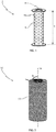
- Fig. 1 shows a tubular core 2 with a plurality of apertures 4, a hollow interior 8 and a longitudinal extension indicated by the double arrow 6.
- the tubular core 2 has an outer surface 16 onto which a yarn may be wound.
- the illustrated core 2 has a generally cylindrical shape. However, other shapes could also be envisioned.
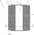
- Fig. 2 shows a filter element 10.
- the illustrated filter element 10 comprises a tubular core 2 (not visible) as illustrated in Fig. 1 onto which a yarn 12 has been wound.
- the outermost layer of yarn 12 has been wound onto the tubular core 2 at an angle ⁇ with respect to an axis 14 that is parallel with the longitudinal extension of the tubular core 2.
- the axis 14 is the symmetry axis of the tubular core 2.
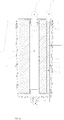
- Fig. 3 shows a cross section of a filter element 10.
- the illustrated filter element 10 comprises a tubular core 2 with a plurality of apertures 4 and a hollow interior 8.
- the tubular core 2 has an open end 18 for fluid communication with the hollow interior 8.
- a length of yarn 12 has been wound around the outer surface 16 of the tubular core 2 in a series of 3 layers, 11, 13, and 15, wherein the first layer 15 closest to the outer surface 16 of the tubular core 2 comprises at least 15 windings of the yarn 12.
- the second layer 17 comprises at least 15 windings of the yarn 12 and the third layer 10 comprises at least 10 windings of the yarn 12. At least two consecutive layers of the three layers 11, 13 and 15 have been wound in accordance with different winding patterns.
- the first layer 15 comprises between 15 and 17 windings of the yarn 12
- the second layer 17 comprises between 15 and 20 windings of the yarn 12
- the third layer 10 comprises between 10 and 15 windings of the yarn 12.
- One way of providing a particular winding pattern in the illustrated filter element 10 is by using a particular winding angle ⁇ .
- the applicant has found it advantageous if the first layer 11 of yarn 12 has been wound around the outer surface 16 of the tubular core 2 at an angle ⁇ larger than 55 degrees with respect to an axis 12 parallel to the longitudinal extension of the tubular core 2, and the second layer 17 of yarn 12 has been wound around the outer surface 10 of the tubular core 2 at an angle ⁇ larger than 45 degrees with respect to an axis 14 parallel to the longitudinal extension of the tubular core 2, and the third layer 10 of yarn 12 has been wound around the outer surface 16 of the tubular core 2 at an angle ⁇ larger than 40 degrees with respect to an axis 14 parallel to the longitudinal extension of the tubular core 2.
- the angle ⁇ with which the yarn 12 has been wound around the tubular core 2 is different for two consecutive layers 10 and 12, in order to facilitate winding patterns that are able to trap particles of different sizes.
- the filter element 10 may comprise additional layers, for example, the illustrated layer structure of 3 layers 11, 13 and 15 could be repeated for a suitable number of times.
- Fig. 4 shows a cross section of a filter comprising the synthetic filter and mounting.
- the housing further comprises an inlet opening 24 that are fluidly connected to the layers (not explicitly shown) of yarn 12.
- a self-contained filter 27 that may be adapted to be mounted in connection with a power transmission system, such as an engine, hydraulics, gears, valves etc., which is able to remove both solid particle contaminants as well as water from the oils. Furthermore, this self-contained filter 27 may be used as a bypass filter for providing additional filtering in already existing installations and power transmission systems.
- the housing 17 is preferably made from metal, such as Aluminium.
- the housing 17 may comprise a container 23 that is releasable attached to the housing 17. This releasable attachment could for example be provided by the illustrated threading 19.
- both the drainage pipe 22 and the inlet opening 24 are placed in the cap 20.
- the filter element 10 may be replaced in an easy manner without having to unplug one or both if the drainage pipe 22 and inlet opening 24 of the housing 17.
- the container 23 may for example just be screwed of the cap 20 and the filter element 10 replaced.
- the longitudinal extension 6 of the yarn 12 covered tubular cores 2 is between 5-10 times the total radial thicknesses 21 of the layers as measured from the outer surface 16 of the tubular core 2.
- the dimensions that are chosen in any particular case may be chosen in dependence of the capacity needed, i.e. how much oil is needed to be filtered pr. hour.
- a filter 10 having a longitudinal extension 6 between 24 cm and 30 cm will be suitable for filtering up to 250 - 500 l/h (liters/hour) of oil
- a filter 10 that has a longitudinal extension 6 between 45 cm and 60 cm will be suitable for filtering up to 1000 - 1500 l/h.
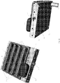
- Fig. 5 shows a perspective view of a distillation element, comprising a number of bores 90 for the compressing tubes 78.
- the bores 90 are situated in the distillation head 76.
- the oil may undergo heating up to 70 degrees Celsius due to friction and pressure in the compressing tubes 78, whereby separate heating of the distillation head 76 or oil is not needed.
- the eventual water within the oil is close to or at its boiling temperature, which implies that it easier evaporates from the pressurized oil when injected into the evaporation chamber 80.
- a larger quantity of water will evaporate from the droplets.
- the distillation head 76 are made from a metal or metal alloy comprising aluminium, which has good heat conductivity and low reactivity with oil.
- the illustrated main block 81 further having an inlet pipe 24 that in one end 79 is fluidly connected to a container, i.e. the housing 17, adapted to temporarily store the oil to be filtered, and in the other end being fluidly connected to a distillation unit 81, said distillation head comprising a plurality (only three visible) of compressing tubes 78 for injecting the oil into a evaporation chamber 80.
- a container i.e. the housing 17, adapted to temporarily store the oil to be filtered
- a distillation unit 81 said distillation head comprising a plurality (only three visible) of compressing tubes 78 for injecting the oil into a evaporation chamber 80.
- an inlet 82 for blowing air or an inert gas into said evaporation chamber 80.
- the oil is compressed as a liquid into the evaporation chamber 80. Due to the different thermodynamic properties of the oil and the water, they react differently to changes in heat and pressure. These vaporized contaminants; (steam) is then blown out of the evaporation chamber 80 through an opening in the cap 91, while the oil is drained out in liquid form through a drainage pipe 22.
- a plurality of compressing tubes 78 is used in order to ensure an adequate flow rate, and the actual number of compressing tubes 78 needed may be chosen in dependence of the particular application of the inventive filter 27.
- Fig. 6 illustrates a cross section of an embodiment of a compression tube 78.
- the compression tubes 78 have barrel openings 88 that are smaller than 7 mm, preferably smaller than 3 mm or between 0.5 mm and 7 mm, preferably between 0.5 mm and 3 mm, more preferably between 0.7 and 1.2 mm. Separation is achieved by selecting a barrel size that creates a significant pressure differential across the opening 88.
- the viscosity of different oils is largely dependent of temperature, so the barrel sizes are preferably chosen in dependence of the temperature increase the oil undergoes during friction with the barrels, and the type of oil to be filtered. To this end the applicant estimates that by using barrel sizes as mentioned above it would be possible to separate water from most types of oils.
- the compression tube 78 have preferably a barrel 90 that is rifled in order to thereby impart a rotational motion to the compressed injected oil and thereby enhance the separation (evaporation) of contaminants from them.
- the length of the barrel 90 of each of the compression tubes 78 is between 4 mm and 40 mm.
- Fig. 7 shows a perspective view of an "open" evaporation chamber 80, wherein the distillation head 76 with a number of compressing tubes 78 can be seen.
- the evaporation chamber 80 has a floor with drain 94 for leading the oil to the drainage pipe 22/106.
- the drain 94 is configured to be situated at the lowest place of the floor.
- the oil - relieved form most of the water contaminants - may be drained from the bottom of the evaporation chamber 80, while the gaseous phase, i.e. steam, blown out from an upper part of the evaporation chamber 80 by blowing air or an inert gas into said evaporation chamber 80.
- the terms “lower” and “upper” refers to the lower and upper parts of the evaporation chamber 80, when the filter 27 is installed in its correct use position.
- start block 89 Also shown is the start block 89 and end block 72.
- Fig. 8 shows a partial longitudinal cross sectional view of an embodiment of a filter element 10 according to the invention. Illustrated is a part of the tubular core 2 having a number of apertures 4. Around the outer surface 16 of the tubular core 2 is wound a yarn 12 in a number of layers (not illustrated), wherein only the first two windings of the first layer is illustrated.
- the yarn 12 comprises a number of fibers 26, 28 and 30 (of which only three have been given designation numbers in order to increase the intelligibility of the figure).
- the yarn 12 comprises a mix of natural and synthetic fibers.
- the fibers 26 and 30 may be natural, while the fiber 28 may be synthetic. Since natural fibers 26 and 30 are hydrophilic, while synthetic fibers 28 generally are hydrophobic, a filter element 10 wherein the yarn 12 is made of a mix of both natural (26 and 30) and synthetic (28) fibers has the additional advantage that in addition to being able to filter particles from the oil, also water may be absorbed by the yarn 12 and thereby filtered from the oil.
- the natural fibers 26 and 30 are chosen from a list of fibers comprising cotton and/or wool and the synthetic fibers (28) are chosen from a list of fibers comprising any of the following materials: acryl, polyester, flax, polyamide, acetate and/or viscose.
- Cotton and wool are cheap natural fibers that are easy to mix with any or a plurality of the synthetic fibers mentioned above. Thus facilitating an effective, yet cheap yarn 12 for the filter element 10.
- the yarn 12 comprises less than 15% natural fibers. In another embodiment, the yarn 12 comprises more than 45% acryl. In yet another embodiment the yarn 12 comprises more than 20% polyester, and in yet even another embodiment the yarn 12 comprises more than 25% flax.
- the yarn 12 comprises more than 2% viscose, or between 2% and 4% viscose.
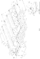
- Fig. 9 shows the embodiment of a filter element 10 as illustrated in Fig. 3 cut along the dashed line A in order to illustrate the layered structure of yarn 12 more clearly. Illustrated is the tubular core 2 with a number of apertures 4 and a hollow interior 8. Around the outer surface 16 of the tubular core two is illustrated the first layer 11 of yarn that has been wound around the tubular core 2 in accordance with a particular winding pattern. Also illustrated is the second 13 and third 15 layer of yarn 12. In addition to these layers 11, 13 and 15 additional layers may be provided in alternative embodiments as is illustrated by the layers 38 and 40.
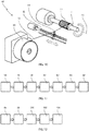
- Fig. 10 shows a tubular core 2 that has been placed in a winding machine 42.
- the tubular core 2 is rotated with respect to the axis 15, while the yarn 12 is fed through a head 44 to the tubular core 2.
- the rotation of the tubular core 2 may be manually controlled, but is preferably automatically controlled by the winding machine 42 or a computer (not illustrated) controlling the winding machine 42.
- the head 44 is moved back and forth (as illustrated by the double arrow 48) on the rail 46 parallel to the axis 14 at a controlled rate.
- varying winding patterns may be produced.
- a layered structure of yarn 12 with a certain number of windings of the yarn 12 and a certain winding pattern for each or some of the layers may be provided for.
- the yarn 12 is provided from a yarn supply 50 holding a larger quantity of yarn 12.
- the yarn 12 has been wound around the outer surface 16 of the core 2 with different winding resistance in at least two of the three layers (11, 13, and 15).
- the yarn 12 of the first 15 and third 15 layer has been wound around the outer surface 16 of the core 2 with a winding resistance that is larger than the winding resistance used for the second layer 13.
- the filter 10 may be designed to be particularly effective in filtering particles of a particular size from the oil, which means that it can be optimized for a particular use, wherein particles of a certain size are a problem.
- the winding resistance may be adjusted by varying the speed at which the yarn 12 is fed through the head 44 relative to the speed of rotation of the tubular core with respect to the axis 14.
- the winding machine 42 preferably automatically controls this adjustment of the winding resistance.
- the yarn 12 of the first layer 15 (closest to the core 2) has been wound around the outer surface 16 of the core 2 with a winding resistance that is larger than the winding resistance used for the second layer 17, and wherein the yarn 12 of the third layer 15 has been wound around the outer surface 15 of the core 2 with a winding resistance that is larger than the winding resistance used for the second layer 13.
- the fluid is slowed down more and more for each layer it passes through during its flow through the filtering media (the layers of yarn 12).
- the outer surface 16 of the tubular core 12 illustrated in any of the figures may also be covered with a fluid permeable sheet that covers the outer surface 16 of the tubular core 2 at least one time.
- the sheet thus being placed between the outer surface 16 of the core 2 and the first layer 11 of yarn 12.
- the sheet is preferably a piece of textile, preferably a tightly woven textile.
- the first layer 15 comprises 15 - 17 windings of the yarn 12 that has been wound onto the tubular core 2 at an angle ⁇ of 55 degrees (both ways)
- the second layer 17 comprises 15 - 20 windings of the yarn 12 that has been wound onto the tubular core 2 at an angle ⁇ of 55 degrees (both ways)
- the third layer 15 comprises 15 - 17 windings of the yarn 12 that has been wound onto the tubular core 2 at the angle ⁇ of 65 degrees.
- the first layer 15 may comprise 17 windings of the yarn 12
- the second layer 15 may comprise 15 windings of the yarn 12
- the third layer 15 may comprise 17 windings of the yarn 12.
- the yarn 12 comprises a mixture of fibers made from: 5% - 15% cotton, 45% - 48 % acryl, 25% - 27% flax, 20% - 22% polyester, and 4% - 5% polyamide.
- a filter element 10 as illustrated in any of the figures 2 - 4 , 8 and 9 , the layered structure of example 1 is used in combination with the composition of the yarn 12 used in example 2. Investigations have shown that a filter 10 according to this specific example 3 is even better suited for filtering particles having a diameter or average particle size of 0.5 ⁇ m - 50 ⁇ m from an oil, e.g. engine oil or hydraulic oil.
- a filter element 10 according to this example 3 with a longitudinal length of 45 - 70 cm has the capacity of filtering up to 1000 L/h - 2500 L/h of oil.
- Fig. 11 shows a flow diagram of a method of manufacturing a filter element 10 illustrated in any of the figures 2 - 4 , 8 and 9 , where the method comprises the steps
- the method illustrated by the flow diagram in Fig. 11 may further comprise the step of varying the winding resistance of the yarn 12 by varying the speed at which the yarn 12 is feed through the head 44 relative to the speed of rotation of the tubular core 2 with respect to the axis 14.
- Fig. 12 shows a flow diagram of a method for removing water from oil, the method comprising the following steps:
- Fig. 13 shows a complete unit with water removal unit start and end block.
- the oil is first led to the first filter 27 via the inlet hose 110, where it is filtered, and then through a hose to the start block 89, inlet 79, where the water is removed, and from which it leaks back to the circuit from where it originated via the outlet pipe 85.
- the filters 27 are via air/gas pipes 82 fluidly connected to a blower 92 for blowing air or an inert gas into the evaporation chamber 80 during use in order to remove the water vapor within the evaporation chamber 80.
- the blower 81 is connected to a source of inert gas (not shown).
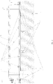
- Fig. 14 is showing a partial cross section of the complete water removing unit illustrated in Fig. 13 .
- Fig. 15 shows an example of a complete assembly of an oil cleaning unit.
Landscapes
- Chemical & Material Sciences (AREA)
- Chemical Kinetics & Catalysis (AREA)
- Oil, Petroleum & Natural Gas (AREA)
- Engineering & Computer Science (AREA)
- Physics & Mathematics (AREA)
- Thermal Sciences (AREA)
- General Chemical & Material Sciences (AREA)
- Organic Chemistry (AREA)
- Mechanical Engineering (AREA)
- Combustion & Propulsion (AREA)
- Filtering Materials (AREA)
Claims (13)
- Filter zur Entfernung von Wasser aus Öl, wobei der Filter ein Destillationselement umfasst, das ein Zuleitungsrohr aufweist, das an einem Ende mit einem zu filternden Ölbehälter in Fluidverbindung bringbar ist, und am anderen Ende in Fluidverbindung mit einem Destillationskopf (76) ist, wobei der Filter weiterhin einen rohrförmigen Kern (2) mit einer Mehrzahl von Öffnungen (4) und einen hohlen Innenraum (8) umfasst, wobei dieser Kern (2) ein offenes Ende für eine Fluidverbindung mit dem hohlen Innenraum (8) und eine um eine äußere Oberfläche (16) des Kerns (2) gewundene Garnlänge aufweist, wobei der Destillationskopf (76) eine Mehrzahl von Kompressionsschläuchen (78) zur Einspritzung des Öls in eine Verdampfungskammer (80) umfasst, wodurch allfälliges Wasser im Öl aus dem Öl verdampft, dadurch gekennzeichnet, dass
der Filter weiterhin eine Vorrichtung zum Einblasen von Luft oder eines Inertgases in die Verdampfungskammer (80) zur Entfernung des Wasserdampfes während der Verwendung des Filters aufweist. - Filter nach Anspruch 1, wobei diese Vorrichtung zum Einblasen von Luft oder eines Inertgases in die Verdampfungskammer (80) ein Gebläse ist, das über ein Rohr in Fluidverbindung mit der Verdampfungskammer (80) ist.
- Filter nach Anspruch 1 oder 2, wobei die Verdampfungskammer (80) einen Auslass für die Luft oder das Inertgas umfasst, die/das während der Verwendung in die Verdampfungskammer (80) geblasen wird.
- Filter nach Anspruch 1, 2 oder 3, wobei das Rohr und der Destillationskopf (76) aus einem Metall oder einer Metalllegierung, die Aluminium umfasst, bestehen.
- Filter nach einem der vorhergehenden Ansprüche, wobei jeder der Kompressionsschläuche (78) eine Fließkanalgröße von unter 7 mm, vorzugsweise unter 3 mm oder zwischen 0,5 mm und 7 mm, vorzugsweise zwischen 0,5 mm und 3 mm, und noch bevorzugter zwischen 0,7 und 1,2 mm aufweist.
- Filter nach einem der vorhergehenden Ansprüche, wobei die Länge des Fließkanals jedes der Kompressionsschläuche (78) zwischen 4 mm und 40 mm beträgt.
- Filter nach einem der vorhergehenden Ansprüche, wobei das Öl vor der Einspritzung durch die Kompressionsschläuche (78) druckbeaufschlagt wird.
- Filter nach einem der Ansprüche 1 - 7, wobei das Garn (12) in einer Reihe von mindestens drei Schichten um die äußere Oberfläche des Kerns (2) gewunden ist, wobei die erste Schicht, die am dichtesten an der Oberfläche des Kerns (2) liegt, mindestens 5 Wicklungen des Garns (12) umfasst; die zweite Schicht mindestens 6 Wicklungen des Garns (12) umfasst und die dritte Schicht mindestens 10 Wicklungen des Garns (12) umfasst, und wobei mindestens zwei aufeinanderfolgende Schichten nach unterschiedlichen Wicklungsmustern gewickelt wurden.
- Filter nach Anspruch 8, wobei das Garn (12) eine Kombination aus natürlichen und synthetischen Fasern umfasst, und wobei die natürlichen Fasern aus einer Liste von Fasern ausgewählt sind, die Baumwolle und/oder Wolle umfassen, und wobei die synthetischen Fasern aus einer Liste von Fasern ausgewählt sind, die eines der folgenden Materialien umfassen: Acryl, Polyester, Flachs, Polyamid, Acetat und/oder Viskose.
- Filter nach einem der Ansprüche 8 bis 9, wobei jede der mindestens drei Schichten nach einem Wicklungsmuster gewickelt wurde, das sich vom Wicklungsmuster der anderen Schichten unterscheidet.
- Filter nach einem der vorhergehenden Ansprüche, weiterhin umfassend ein Gehäuse, das den rohrförmigen Kern (2) und das Garn (12) vollständig umschließt, und wobei das Gehäuse (17) weiterhin eine erste Öffnung, die in Fluidverbindung mit dem hohlen Innenraum (8) des rohrförmigen Kerns (2) ist, sowie eine zweite Öffnung umfasst, die in Fluidverbindung mit den Schichten von Garn (12) ist.
- Verfahren zum Entfernen von Wasser aus Öl durch einen Filter nach einem der vorstehenden Ansprüche, wobei das Verfahren die folgenden Schritte umfasst:- Einspritzen des Öls unter Druck in die Verdampfungskammer (80) durch eine Mehrzahl von Kompressionsschläuchen (78), wobei das Öl bei Eintritt in die Verdampfungskammer (80) dekomprimiert wird,- Entfernen eines Teils einer gasförmigen Phase des Wassers aus der Verdampfungskammer (80) durch Einblasen von Luft oder Inertgas in die Verdampfungskammer (80) mit einer vorbestimmten Geschwindigkeit und- Ableiten einer flüssigen Phase des Öl aus der Verdampfungskammer (80).
- Filteranordnung, umfassend eine Mehrzahl von Filtern nach einem der Ansprüche 1 bis 11, die zur aufeinanderfolgenden Filterung von Öl durch diese Filter in Reihe geschaltet in Fluidverbindung stehen.
Applications Claiming Priority (1)
| Application Number | Priority Date | Filing Date | Title |
|---|---|---|---|
| PCT/NO2015/050015 WO2016118016A1 (en) | 2015-01-23 | 2015-01-23 | Water and oil separation method using compressing tubes to vaporize water |
Publications (2)
| Publication Number | Publication Date |
|---|---|
| EP3247479A1 EP3247479A1 (de) | 2017-11-29 |
| EP3247479B1 true EP3247479B1 (de) | 2018-12-12 |
Family
ID=52684615
Family Applications (1)
| Application Number | Title | Priority Date | Filing Date |
|---|---|---|---|
| EP15710270.8A Not-in-force EP3247479B1 (de) | 2015-01-23 | 2015-01-23 | Verfahren zum trennen von wasser und öl mit stauchrohren zur verdampfung von wasser |
Country Status (4)
| Country | Link |
|---|---|
| US (1) | US20170368484A1 (de) |
| EP (1) | EP3247479B1 (de) |
| CN (1) | CN107530589A (de) |
| WO (1) | WO2016118016A1 (de) |
Families Citing this family (2)
| Publication number | Priority date | Publication date | Assignee | Title |
|---|---|---|---|---|
| IL295143B2 (en) | 2020-02-13 | 2026-02-01 | Hoffmann La Roche | A method for determining the loading state of AAV particles using nuclear magnetic resonance relaxometry |
| DE102020111803A1 (de) * | 2020-04-30 | 2021-11-04 | Enmodes Gmbh | Wickelsystem zur Durchführung des Aufwickelns von verketteten Hohlfasern auf einen Wickelkern |
Family Cites Families (23)
| Publication number | Priority date | Publication date | Assignee | Title |
|---|---|---|---|---|
| US998670A (en) * | 1908-12-14 | 1911-07-25 | William P Bending | Process of treating hydrocarbon oils. |
| US2635759A (en) | 1950-01-26 | 1953-04-21 | William C Schwalge | Oil reclaimer for internal-combustion engines |
| US2785109A (en) | 1955-03-14 | 1957-03-12 | William C Schwalge | Oil reclaimer |
| US2839196A (en) | 1955-08-09 | 1958-06-17 | William C Schwalger | Oil reclaimer |
| US3550871A (en) | 1967-07-12 | 1970-12-29 | Leesona Corp | Textile machinery |
| FR2097502A5 (de) | 1970-07-09 | 1972-03-03 | Tecalemit | |
| US3616885A (en) | 1970-12-02 | 1971-11-02 | Glen R Priest | Oil reclaimer |
| US4006084A (en) | 1973-05-10 | 1977-02-01 | Priest Glen R | Oil reclaiming device |
| US3915860A (en) | 1973-12-26 | 1975-10-28 | Glen R Priest | Oil reconditioning device |
| US4146475A (en) | 1977-12-01 | 1979-03-27 | Forsland Audre C | Electrefiner |
| US4349438A (en) | 1981-07-08 | 1982-09-14 | Sims Oil, Inc. | Oil refiner |
| JPS5824318A (ja) | 1981-08-04 | 1983-02-14 | Kanebo Ltd | 「ろ」過筒 |
| EP0215061A4 (de) | 1985-02-22 | 1988-07-14 | Internat Energy Corp | Ölreinigungsvorrichtung mit spritzdüse. |
| EP0489157B1 (de) | 1989-03-16 | 1997-06-04 | Toyo Boseki Kabushiki Kaisha | Biegsames rohrförmiges filtermaterial |
| US5552065A (en) | 1995-01-10 | 1996-09-03 | The Oilguard Company Llc | Oil filtration method and element of wound cotton/paper composition |
| ZA96680B (en) * | 1995-01-31 | 1996-10-30 | Tf Purifiner Inc | Oil reclamation device with evaporator base and head connected filter |
| US5772952A (en) | 1997-02-07 | 1998-06-30 | J&M Laboratories, Inc. | Process of making meltblown yarn |
| JP2009502496A (ja) | 2005-08-01 | 2009-01-29 | ヤン・インゴルフ・クリスティアンセン | 濾過装置の製造方法 |
| CN101268174A (zh) | 2005-08-01 | 2008-09-17 | 扬·因戈尔夫·克里斯蒂安森 | 净化石化产品的方法及装置 |
| CN101265416B (zh) * | 2007-03-16 | 2012-08-29 | 中国人民解放军后勤工程学院 | 润滑油复合脱水工艺 |
| WO2012020280A1 (en) * | 2010-08-09 | 2012-02-16 | Ingolf Kristiansen | Cartridge filter |
| US9138660B2 (en) * | 2011-05-25 | 2015-09-22 | Masahiro Yamamoto | Method for reducing water content of an object to be treated |
| CN103827266B (zh) * | 2011-05-31 | 2016-08-17 | 克拉瑞迪安有限责任公司 | 用于从石化产品去除外来流体的方法和设备 |
-
2015
- 2015-01-23 EP EP15710270.8A patent/EP3247479B1/de not_active Not-in-force
- 2015-01-23 WO PCT/NO2015/050015 patent/WO2016118016A1/en not_active Ceased
- 2015-01-23 US US15/545,592 patent/US20170368484A1/en not_active Abandoned
- 2015-01-23 CN CN201580077864.6A patent/CN107530589A/zh active Pending
Non-Patent Citations (1)
| Title |
|---|
| None * |
Also Published As
| Publication number | Publication date |
|---|---|
| WO2016118016A1 (en) | 2016-07-28 |
| CN107530589A (zh) | 2018-01-02 |
| EP3247479A1 (de) | 2017-11-29 |
| US20170368484A1 (en) | 2017-12-28 |
Similar Documents
| Publication | Publication Date | Title |
|---|---|---|
| KR102208134B1 (ko) | 유합 필터 | |
| US5417851A (en) | Portable apparatus for remotely filtering contaminated liquids from a variety of machinery reservoirs by continuous recycling | |
| EP2603301B1 (de) | Patronenfilter | |
| DE2510225C2 (de) | Vorrichtung zum Abscheiden von in Gasen schwebenden Flüssigkeiten | |
| CA1128427A (en) | Oil reconditioning system | |
| DE102008020233A1 (de) | Kraftstofffiltersystem, insbesondere für Dieselmotoren | |
| TW554132B (en) | Process for reconditioning oil and apparatus for removing volatiles from engine oil | |
| EP2524723A1 (de) | Filteranordnungen und Filtervorrichtungen mit den Filteranordnungen | |
| US6132203A (en) | Method and apparatus for burning oils of varying viscosity | |
| US20170368484A1 (en) | Water and oil separation method using compressing tubes to vaporize water | |
| EP2714849B1 (de) | Verfahren und vorrichtung zum entfernen von wasser aus einem petrochemischen produkt | |
| US20090078658A1 (en) | Oil filter element of wound cotton/paper composition | |
| US20130008320A1 (en) | Cooking Oil Filtration System | |
| CN1126797A (zh) | 内燃机润滑系统 | |
| WO2018024469A1 (de) | Abscheideelement, vorrichtung sowie verfahren zur abscheidung von flüssigkeit aus rohgas oder aus rohgasgemisch einer kraftmaschine/kompressors | |
| DE102009005550A1 (de) | Beheizbarer Flüssigkeitsabscheider, insbesondere zum Reinigen von Kurbelgehäusegasen | |
| US20080073299A1 (en) | Oil filter element of wound cotton /paper composition | |
| KR101913629B1 (ko) | 풍력발전기 기어박스 오일 플러싱 및 교체 유닛 | |
| DE102009035895A1 (de) | Drehbar gelagertes Filterelement zur Ölabscheidung | |
| DE102017011691B4 (de) | Flüssigkeitsabscheider | |
| KR20220016804A (ko) | 필터 장치 | |
| DE112019002450B4 (de) | Filtersystem und filterelement mit glasfaserhaltigem filtermedium | |
| US1722808A (en) | Magazine filter | |
| BE1022383B1 (nl) | Coalescentiefilter | |
| DE102011100239A1 (de) | Umgehungsvorrichtung eines Kurbelgehäuseentlüftungssystems |
Legal Events
| Date | Code | Title | Description |
|---|---|---|---|
| STAA | Information on the status of an ep patent application or granted ep patent |
Free format text: STATUS: THE INTERNATIONAL PUBLICATION HAS BEEN MADE |
|
| PUAI | Public reference made under article 153(3) epc to a published international application that has entered the european phase |
Free format text: ORIGINAL CODE: 0009012 |
|
| STAA | Information on the status of an ep patent application or granted ep patent |
Free format text: STATUS: REQUEST FOR EXAMINATION WAS MADE |
|
| 17P | Request for examination filed |
Effective date: 20170823 |
|
| AK | Designated contracting states |
Kind code of ref document: A1 Designated state(s): AL AT BE BG CH CY CZ DE DK EE ES FI FR GB GR HR HU IE IS IT LI LT LU LV MC MK MT NL NO PL PT RO RS SE SI SK SM TR |
|
| AX | Request for extension of the european patent |
Extension state: BA ME |
|
| DAX | Request for extension of the european patent (deleted) | ||
| GRAP | Despatch of communication of intention to grant a patent |
Free format text: ORIGINAL CODE: EPIDOSNIGR1 |
|
| STAA | Information on the status of an ep patent application or granted ep patent |
Free format text: STATUS: GRANT OF PATENT IS INTENDED |
|
| INTG | Intention to grant announced |
Effective date: 20180626 |
|
| GRAS | Grant fee paid |
Free format text: ORIGINAL CODE: EPIDOSNIGR3 |
|
| GRAA | (expected) grant |
Free format text: ORIGINAL CODE: 0009210 |
|
| STAA | Information on the status of an ep patent application or granted ep patent |
Free format text: STATUS: THE PATENT HAS BEEN GRANTED |
|
| AK | Designated contracting states |
Kind code of ref document: B1 Designated state(s): AL AT BE BG CH CY CZ DE DK EE ES FI FR GB GR HR HU IE IS IT LI LT LU LV MC MK MT NL NO PL PT RO RS SE SI SK SM TR |
|
| REG | Reference to a national code |
Ref country code: GB Ref legal event code: FG4D |
|
| REG | Reference to a national code |
Ref country code: CH Ref legal event code: EP |
|
| REG | Reference to a national code |
Ref country code: AT Ref legal event code: REF Ref document number: 1075197 Country of ref document: AT Kind code of ref document: T Effective date: 20181215 |
|
| REG | Reference to a national code |
Ref country code: DE Ref legal event code: R096 Ref document number: 602015021239 Country of ref document: DE |
|
| REG | Reference to a national code |
Ref country code: IE Ref legal event code: FG4D |
|
| REG | Reference to a national code |
Ref country code: NL Ref legal event code: MP Effective date: 20181212 |
|
| REG | Reference to a national code |
Ref country code: LT Ref legal event code: MG4D |
|
| PG25 | Lapsed in a contracting state [announced via postgrant information from national office to epo] |
Ref country code: ES Free format text: LAPSE BECAUSE OF FAILURE TO SUBMIT A TRANSLATION OF THE DESCRIPTION OR TO PAY THE FEE WITHIN THE PRESCRIBED TIME-LIMIT Effective date: 20181212 Ref country code: BG Free format text: LAPSE BECAUSE OF FAILURE TO SUBMIT A TRANSLATION OF THE DESCRIPTION OR TO PAY THE FEE WITHIN THE PRESCRIBED TIME-LIMIT Effective date: 20190312 Ref country code: NO Free format text: LAPSE BECAUSE OF FAILURE TO SUBMIT A TRANSLATION OF THE DESCRIPTION OR TO PAY THE FEE WITHIN THE PRESCRIBED TIME-LIMIT Effective date: 20190312 Ref country code: LT Free format text: LAPSE BECAUSE OF FAILURE TO SUBMIT A TRANSLATION OF THE DESCRIPTION OR TO PAY THE FEE WITHIN THE PRESCRIBED TIME-LIMIT Effective date: 20181212 Ref country code: FI Free format text: LAPSE BECAUSE OF FAILURE TO SUBMIT A TRANSLATION OF THE DESCRIPTION OR TO PAY THE FEE WITHIN THE PRESCRIBED TIME-LIMIT Effective date: 20181212 Ref country code: LV Free format text: LAPSE BECAUSE OF FAILURE TO SUBMIT A TRANSLATION OF THE DESCRIPTION OR TO PAY THE FEE WITHIN THE PRESCRIBED TIME-LIMIT Effective date: 20181212 Ref country code: HR Free format text: LAPSE BECAUSE OF FAILURE TO SUBMIT A TRANSLATION OF THE DESCRIPTION OR TO PAY THE FEE WITHIN THE PRESCRIBED TIME-LIMIT Effective date: 20181212 |
|
| REG | Reference to a national code |
Ref country code: AT Ref legal event code: MK05 Ref document number: 1075197 Country of ref document: AT Kind code of ref document: T Effective date: 20181212 |
|
| PG25 | Lapsed in a contracting state [announced via postgrant information from national office to epo] |
Ref country code: RS Free format text: LAPSE BECAUSE OF FAILURE TO SUBMIT A TRANSLATION OF THE DESCRIPTION OR TO PAY THE FEE WITHIN THE PRESCRIBED TIME-LIMIT Effective date: 20181212 Ref country code: SE Free format text: LAPSE BECAUSE OF FAILURE TO SUBMIT A TRANSLATION OF THE DESCRIPTION OR TO PAY THE FEE WITHIN THE PRESCRIBED TIME-LIMIT Effective date: 20181212 Ref country code: AL Free format text: LAPSE BECAUSE OF FAILURE TO SUBMIT A TRANSLATION OF THE DESCRIPTION OR TO PAY THE FEE WITHIN THE PRESCRIBED TIME-LIMIT Effective date: 20181212 Ref country code: GR Free format text: LAPSE BECAUSE OF FAILURE TO SUBMIT A TRANSLATION OF THE DESCRIPTION OR TO PAY THE FEE WITHIN THE PRESCRIBED TIME-LIMIT Effective date: 20190313 |
|
| PG25 | Lapsed in a contracting state [announced via postgrant information from national office to epo] |
Ref country code: NL Free format text: LAPSE BECAUSE OF FAILURE TO SUBMIT A TRANSLATION OF THE DESCRIPTION OR TO PAY THE FEE WITHIN THE PRESCRIBED TIME-LIMIT Effective date: 20181212 |
|
| PG25 | Lapsed in a contracting state [announced via postgrant information from national office to epo] |
Ref country code: PL Free format text: LAPSE BECAUSE OF FAILURE TO SUBMIT A TRANSLATION OF THE DESCRIPTION OR TO PAY THE FEE WITHIN THE PRESCRIBED TIME-LIMIT Effective date: 20181212 Ref country code: CZ Free format text: LAPSE BECAUSE OF FAILURE TO SUBMIT A TRANSLATION OF THE DESCRIPTION OR TO PAY THE FEE WITHIN THE PRESCRIBED TIME-LIMIT Effective date: 20181212 Ref country code: PT Free format text: LAPSE BECAUSE OF FAILURE TO SUBMIT A TRANSLATION OF THE DESCRIPTION OR TO PAY THE FEE WITHIN THE PRESCRIBED TIME-LIMIT Effective date: 20190412 Ref country code: IT Free format text: LAPSE BECAUSE OF FAILURE TO SUBMIT A TRANSLATION OF THE DESCRIPTION OR TO PAY THE FEE WITHIN THE PRESCRIBED TIME-LIMIT Effective date: 20181212 |
|
| REG | Reference to a national code |
Ref country code: DE Ref legal event code: R119 Ref document number: 602015021239 Country of ref document: DE |
|
| PG25 | Lapsed in a contracting state [announced via postgrant information from national office to epo] |
Ref country code: IS Free format text: LAPSE BECAUSE OF FAILURE TO SUBMIT A TRANSLATION OF THE DESCRIPTION OR TO PAY THE FEE WITHIN THE PRESCRIBED TIME-LIMIT Effective date: 20190412 Ref country code: SK Free format text: LAPSE BECAUSE OF FAILURE TO SUBMIT A TRANSLATION OF THE DESCRIPTION OR TO PAY THE FEE WITHIN THE PRESCRIBED TIME-LIMIT Effective date: 20181212 Ref country code: RO Free format text: LAPSE BECAUSE OF FAILURE TO SUBMIT A TRANSLATION OF THE DESCRIPTION OR TO PAY THE FEE WITHIN THE PRESCRIBED TIME-LIMIT Effective date: 20181212 Ref country code: EE Free format text: LAPSE BECAUSE OF FAILURE TO SUBMIT A TRANSLATION OF THE DESCRIPTION OR TO PAY THE FEE WITHIN THE PRESCRIBED TIME-LIMIT Effective date: 20181212 Ref country code: SM Free format text: LAPSE BECAUSE OF FAILURE TO SUBMIT A TRANSLATION OF THE DESCRIPTION OR TO PAY THE FEE WITHIN THE PRESCRIBED TIME-LIMIT Effective date: 20181212 |
|
| REG | Reference to a national code |
Ref country code: CH Ref legal event code: PL |
|
| PG25 | Lapsed in a contracting state [announced via postgrant information from national office to epo] |
Ref country code: LU Free format text: LAPSE BECAUSE OF NON-PAYMENT OF DUE FEES Effective date: 20190123 |
|
| REG | Reference to a national code |
Ref country code: BE Ref legal event code: MM Effective date: 20190131 |
|
| PLBE | No opposition filed within time limit |
Free format text: ORIGINAL CODE: 0009261 |
|
| STAA | Information on the status of an ep patent application or granted ep patent |
Free format text: STATUS: NO OPPOSITION FILED WITHIN TIME LIMIT |
|
| REG | Reference to a national code |
Ref country code: IE Ref legal event code: MM4A |
|
| PG25 | Lapsed in a contracting state [announced via postgrant information from national office to epo] |
Ref country code: DK Free format text: LAPSE BECAUSE OF FAILURE TO SUBMIT A TRANSLATION OF THE DESCRIPTION OR TO PAY THE FEE WITHIN THE PRESCRIBED TIME-LIMIT Effective date: 20181212 Ref country code: AT Free format text: LAPSE BECAUSE OF FAILURE TO SUBMIT A TRANSLATION OF THE DESCRIPTION OR TO PAY THE FEE WITHIN THE PRESCRIBED TIME-LIMIT Effective date: 20181212 Ref country code: MC Free format text: LAPSE BECAUSE OF FAILURE TO SUBMIT A TRANSLATION OF THE DESCRIPTION OR TO PAY THE FEE WITHIN THE PRESCRIBED TIME-LIMIT Effective date: 20181212 Ref country code: SI Free format text: LAPSE BECAUSE OF FAILURE TO SUBMIT A TRANSLATION OF THE DESCRIPTION OR TO PAY THE FEE WITHIN THE PRESCRIBED TIME-LIMIT Effective date: 20181212 Ref country code: DE Free format text: LAPSE BECAUSE OF NON-PAYMENT OF DUE FEES Effective date: 20190801 |
|
| 26N | No opposition filed |
Effective date: 20190913 |
|
| GBPC | Gb: european patent ceased through non-payment of renewal fee |
Effective date: 20190312 |
|
| PG25 | Lapsed in a contracting state [announced via postgrant information from national office to epo] |
Ref country code: BE Free format text: LAPSE BECAUSE OF NON-PAYMENT OF DUE FEES Effective date: 20190131 |
|
| PG25 | Lapsed in a contracting state [announced via postgrant information from national office to epo] |
Ref country code: LI Free format text: LAPSE BECAUSE OF NON-PAYMENT OF DUE FEES Effective date: 20190131 Ref country code: CH Free format text: LAPSE BECAUSE OF NON-PAYMENT OF DUE FEES Effective date: 20190131 |
|
| PG25 | Lapsed in a contracting state [announced via postgrant information from national office to epo] |
Ref country code: GB Free format text: LAPSE BECAUSE OF NON-PAYMENT OF DUE FEES Effective date: 20190312 Ref country code: IE Free format text: LAPSE BECAUSE OF NON-PAYMENT OF DUE FEES Effective date: 20190123 |
|
| PG25 | Lapsed in a contracting state [announced via postgrant information from national office to epo] |
Ref country code: FR Free format text: LAPSE BECAUSE OF NON-PAYMENT OF DUE FEES Effective date: 20190212 |
|
| PG25 | Lapsed in a contracting state [announced via postgrant information from national office to epo] |
Ref country code: TR Free format text: LAPSE BECAUSE OF FAILURE TO SUBMIT A TRANSLATION OF THE DESCRIPTION OR TO PAY THE FEE WITHIN THE PRESCRIBED TIME-LIMIT Effective date: 20181212 |
|
| PG25 | Lapsed in a contracting state [announced via postgrant information from national office to epo] |
Ref country code: MT Free format text: LAPSE BECAUSE OF NON-PAYMENT OF DUE FEES Effective date: 20190123 |
|
| PG25 | Lapsed in a contracting state [announced via postgrant information from national office to epo] |
Ref country code: CY Free format text: LAPSE BECAUSE OF FAILURE TO SUBMIT A TRANSLATION OF THE DESCRIPTION OR TO PAY THE FEE WITHIN THE PRESCRIBED TIME-LIMIT Effective date: 20181212 |
|
| PG25 | Lapsed in a contracting state [announced via postgrant information from national office to epo] |
Ref country code: HU Free format text: LAPSE BECAUSE OF FAILURE TO SUBMIT A TRANSLATION OF THE DESCRIPTION OR TO PAY THE FEE WITHIN THE PRESCRIBED TIME-LIMIT; INVALID AB INITIO Effective date: 20150123 |
|
| PG25 | Lapsed in a contracting state [announced via postgrant information from national office to epo] |
Ref country code: MK Free format text: LAPSE BECAUSE OF FAILURE TO SUBMIT A TRANSLATION OF THE DESCRIPTION OR TO PAY THE FEE WITHIN THE PRESCRIBED TIME-LIMIT Effective date: 20181212 |