EP3247316B1 - Vorrichtung mit selbstausdehnbarem gerüst zur behandlung von aneurysmen - Google Patents
Vorrichtung mit selbstausdehnbarem gerüst zur behandlung von aneurysmen Download PDFInfo
- Publication number
- EP3247316B1 EP3247316B1 EP16740711.3A EP16740711A EP3247316B1 EP 3247316 B1 EP3247316 B1 EP 3247316B1 EP 16740711 A EP16740711 A EP 16740711A EP 3247316 B1 EP3247316 B1 EP 3247316B1
- Authority
- EP
- European Patent Office
- Prior art keywords
- stent
- cylinder
- struts
- strut
- longitudinal struts
- Prior art date
- Legal status (The legal status is an assumption and is not a legal conclusion. Google has not performed a legal analysis and makes no representation as to the accuracy of the status listed.)
- Active
Links
Images







Classifications
-
- A—HUMAN NECESSITIES
- A61—MEDICAL OR VETERINARY SCIENCE; HYGIENE
- A61F—FILTERS IMPLANTABLE INTO BLOOD VESSELS; PROSTHESES; DEVICES PROVIDING PATENCY TO, OR PREVENTING COLLAPSING OF, TUBULAR STRUCTURES OF THE BODY, e.g. STENTS; ORTHOPAEDIC, NURSING OR CONTRACEPTIVE DEVICES; FOMENTATION; TREATMENT OR PROTECTION OF EYES OR EARS; BANDAGES, DRESSINGS OR ABSORBENT PADS; FIRST-AID KITS
- A61F2/00—Filters implantable into blood vessels; Prostheses, i.e. artificial substitutes or replacements for parts of the body; Appliances for connecting them with the body; Devices providing patency to, or preventing collapsing of, tubular structures of the body, e.g. stents
- A61F2/82—Devices providing patency to, or preventing collapsing of, tubular structures of the body, e.g. stents
- A61F2/852—Two or more distinct overlapping stents
-
- A—HUMAN NECESSITIES
- A61—MEDICAL OR VETERINARY SCIENCE; HYGIENE
- A61F—FILTERS IMPLANTABLE INTO BLOOD VESSELS; PROSTHESES; DEVICES PROVIDING PATENCY TO, OR PREVENTING COLLAPSING OF, TUBULAR STRUCTURES OF THE BODY, e.g. STENTS; ORTHOPAEDIC, NURSING OR CONTRACEPTIVE DEVICES; FOMENTATION; TREATMENT OR PROTECTION OF EYES OR EARS; BANDAGES, DRESSINGS OR ABSORBENT PADS; FIRST-AID KITS
- A61F2/00—Filters implantable into blood vessels; Prostheses, i.e. artificial substitutes or replacements for parts of the body; Appliances for connecting them with the body; Devices providing patency to, or preventing collapsing of, tubular structures of the body, e.g. stents
- A61F2/82—Devices providing patency to, or preventing collapsing of, tubular structures of the body, e.g. stents
- A61F2/86—Stents in a form characterised by the wire-like elements; Stents in the form characterised by a net-like or mesh-like structure
- A61F2/90—Stents in a form characterised by the wire-like elements; Stents in the form characterised by a net-like or mesh-like structure characterised by a net-like or mesh-like structure
- A61F2/91—Stents in a form characterised by the wire-like elements; Stents in the form characterised by a net-like or mesh-like structure characterised by a net-like or mesh-like structure made from perforated sheets or tubes, e.g. perforated by laser cuts or etched holes
-
- A—HUMAN NECESSITIES
- A61—MEDICAL OR VETERINARY SCIENCE; HYGIENE
- A61F—FILTERS IMPLANTABLE INTO BLOOD VESSELS; PROSTHESES; DEVICES PROVIDING PATENCY TO, OR PREVENTING COLLAPSING OF, TUBULAR STRUCTURES OF THE BODY, e.g. STENTS; ORTHOPAEDIC, NURSING OR CONTRACEPTIVE DEVICES; FOMENTATION; TREATMENT OR PROTECTION OF EYES OR EARS; BANDAGES, DRESSINGS OR ABSORBENT PADS; FIRST-AID KITS
- A61F2/00—Filters implantable into blood vessels; Prostheses, i.e. artificial substitutes or replacements for parts of the body; Appliances for connecting them with the body; Devices providing patency to, or preventing collapsing of, tubular structures of the body, e.g. stents
- A61F2/82—Devices providing patency to, or preventing collapsing of, tubular structures of the body, e.g. stents
- A61F2/92—Stents in the form of a rolled-up sheet expanding after insertion into the vessel, e.g. with a spiral shape in cross-section
-
- A—HUMAN NECESSITIES
- A61—MEDICAL OR VETERINARY SCIENCE; HYGIENE
- A61F—FILTERS IMPLANTABLE INTO BLOOD VESSELS; PROSTHESES; DEVICES PROVIDING PATENCY TO, OR PREVENTING COLLAPSING OF, TUBULAR STRUCTURES OF THE BODY, e.g. STENTS; ORTHOPAEDIC, NURSING OR CONTRACEPTIVE DEVICES; FOMENTATION; TREATMENT OR PROTECTION OF EYES OR EARS; BANDAGES, DRESSINGS OR ABSORBENT PADS; FIRST-AID KITS
- A61F2/00—Filters implantable into blood vessels; Prostheses, i.e. artificial substitutes or replacements for parts of the body; Appliances for connecting them with the body; Devices providing patency to, or preventing collapsing of, tubular structures of the body, e.g. stents
- A61F2/82—Devices providing patency to, or preventing collapsing of, tubular structures of the body, e.g. stents
- A61F2002/823—Stents, different from stent-grafts, adapted to cover an aneurysm
-
- A—HUMAN NECESSITIES
- A61—MEDICAL OR VETERINARY SCIENCE; HYGIENE
- A61F—FILTERS IMPLANTABLE INTO BLOOD VESSELS; PROSTHESES; DEVICES PROVIDING PATENCY TO, OR PREVENTING COLLAPSING OF, TUBULAR STRUCTURES OF THE BODY, e.g. STENTS; ORTHOPAEDIC, NURSING OR CONTRACEPTIVE DEVICES; FOMENTATION; TREATMENT OR PROTECTION OF EYES OR EARS; BANDAGES, DRESSINGS OR ABSORBENT PADS; FIRST-AID KITS
- A61F2/00—Filters implantable into blood vessels; Prostheses, i.e. artificial substitutes or replacements for parts of the body; Appliances for connecting them with the body; Devices providing patency to, or preventing collapsing of, tubular structures of the body, e.g. stents
- A61F2/82—Devices providing patency to, or preventing collapsing of, tubular structures of the body, e.g. stents
- A61F2002/825—Devices providing patency to, or preventing collapsing of, tubular structures of the body, e.g. stents having longitudinal struts
-
- A—HUMAN NECESSITIES
- A61—MEDICAL OR VETERINARY SCIENCE; HYGIENE
- A61F—FILTERS IMPLANTABLE INTO BLOOD VESSELS; PROSTHESES; DEVICES PROVIDING PATENCY TO, OR PREVENTING COLLAPSING OF, TUBULAR STRUCTURES OF THE BODY, e.g. STENTS; ORTHOPAEDIC, NURSING OR CONTRACEPTIVE DEVICES; FOMENTATION; TREATMENT OR PROTECTION OF EYES OR EARS; BANDAGES, DRESSINGS OR ABSORBENT PADS; FIRST-AID KITS
- A61F2210/00—Particular material properties of prostheses classified in groups A61F2/00 - A61F2/26 or A61F2/82 or A61F9/00 or A61F11/00 or subgroups thereof
- A61F2210/0014—Particular material properties of prostheses classified in groups A61F2/00 - A61F2/26 or A61F2/82 or A61F9/00 or A61F11/00 or subgroups thereof using shape memory or superelastic materials, e.g. nitinol
-
- A—HUMAN NECESSITIES
- A61—MEDICAL OR VETERINARY SCIENCE; HYGIENE
- A61F—FILTERS IMPLANTABLE INTO BLOOD VESSELS; PROSTHESES; DEVICES PROVIDING PATENCY TO, OR PREVENTING COLLAPSING OF, TUBULAR STRUCTURES OF THE BODY, e.g. STENTS; ORTHOPAEDIC, NURSING OR CONTRACEPTIVE DEVICES; FOMENTATION; TREATMENT OR PROTECTION OF EYES OR EARS; BANDAGES, DRESSINGS OR ABSORBENT PADS; FIRST-AID KITS
- A61F2220/00—Fixations or connections for prostheses classified in groups A61F2/00 - A61F2/26 or A61F2/82 or A61F9/00 or A61F11/00 or subgroups thereof
- A61F2220/0025—Connections or couplings between prosthetic parts, e.g. between modular parts; Connecting elements
- A61F2220/0058—Connections or couplings between prosthetic parts, e.g. between modular parts; Connecting elements soldered or brazed or welded
-
- A—HUMAN NECESSITIES
- A61—MEDICAL OR VETERINARY SCIENCE; HYGIENE
- A61F—FILTERS IMPLANTABLE INTO BLOOD VESSELS; PROSTHESES; DEVICES PROVIDING PATENCY TO, OR PREVENTING COLLAPSING OF, TUBULAR STRUCTURES OF THE BODY, e.g. STENTS; ORTHOPAEDIC, NURSING OR CONTRACEPTIVE DEVICES; FOMENTATION; TREATMENT OR PROTECTION OF EYES OR EARS; BANDAGES, DRESSINGS OR ABSORBENT PADS; FIRST-AID KITS
- A61F2220/00—Fixations or connections for prostheses classified in groups A61F2/00 - A61F2/26 or A61F2/82 or A61F9/00 or A61F11/00 or subgroups thereof
- A61F2220/0025—Connections or couplings between prosthetic parts, e.g. between modular parts; Connecting elements
- A61F2220/0075—Connections or couplings between prosthetic parts, e.g. between modular parts; Connecting elements sutured, ligatured or stitched, retained or tied with a rope, string, thread, wire or cable
-
- A—HUMAN NECESSITIES
- A61—MEDICAL OR VETERINARY SCIENCE; HYGIENE
- A61F—FILTERS IMPLANTABLE INTO BLOOD VESSELS; PROSTHESES; DEVICES PROVIDING PATENCY TO, OR PREVENTING COLLAPSING OF, TUBULAR STRUCTURES OF THE BODY, e.g. STENTS; ORTHOPAEDIC, NURSING OR CONTRACEPTIVE DEVICES; FOMENTATION; TREATMENT OR PROTECTION OF EYES OR EARS; BANDAGES, DRESSINGS OR ABSORBENT PADS; FIRST-AID KITS
- A61F2230/00—Geometry of prostheses classified in groups A61F2/00 - A61F2/26 or A61F2/82 or A61F9/00 or A61F11/00 or subgroups thereof
- A61F2230/0002—Two-dimensional shapes, e.g. cross-sections
- A61F2230/0004—Rounded shapes, e.g. with rounded corners
- A61F2230/0013—Horseshoe-shaped, e.g. crescent-shaped, C-shaped, U-shaped
-
- A—HUMAN NECESSITIES
- A61—MEDICAL OR VETERINARY SCIENCE; HYGIENE
- A61F—FILTERS IMPLANTABLE INTO BLOOD VESSELS; PROSTHESES; DEVICES PROVIDING PATENCY TO, OR PREVENTING COLLAPSING OF, TUBULAR STRUCTURES OF THE BODY, e.g. STENTS; ORTHOPAEDIC, NURSING OR CONTRACEPTIVE DEVICES; FOMENTATION; TREATMENT OR PROTECTION OF EYES OR EARS; BANDAGES, DRESSINGS OR ABSORBENT PADS; FIRST-AID KITS
- A61F2250/00—Special features of prostheses classified in groups A61F2/00 - A61F2/26 or A61F2/82 or A61F9/00 or A61F11/00 or subgroups thereof
- A61F2250/0014—Special features of prostheses classified in groups A61F2/00 - A61F2/26 or A61F2/82 or A61F9/00 or A61F11/00 or subgroups thereof having different values of a given property or geometrical feature, e.g. mechanical property or material property, at different locations within the same prosthesis
- A61F2250/0015—Special features of prostheses classified in groups A61F2/00 - A61F2/26 or A61F2/82 or A61F9/00 or A61F11/00 or subgroups thereof having different values of a given property or geometrical feature, e.g. mechanical property or material property, at different locations within the same prosthesis differing in density or specific weight
- A61F2250/0017—Special features of prostheses classified in groups A61F2/00 - A61F2/26 or A61F2/82 or A61F9/00 or A61F11/00 or subgroups thereof having different values of a given property or geometrical feature, e.g. mechanical property or material property, at different locations within the same prosthesis differing in density or specific weight differing in yarn density
-
- A—HUMAN NECESSITIES
- A61—MEDICAL OR VETERINARY SCIENCE; HYGIENE
- A61F—FILTERS IMPLANTABLE INTO BLOOD VESSELS; PROSTHESES; DEVICES PROVIDING PATENCY TO, OR PREVENTING COLLAPSING OF, TUBULAR STRUCTURES OF THE BODY, e.g. STENTS; ORTHOPAEDIC, NURSING OR CONTRACEPTIVE DEVICES; FOMENTATION; TREATMENT OR PROTECTION OF EYES OR EARS; BANDAGES, DRESSINGS OR ABSORBENT PADS; FIRST-AID KITS
- A61F2250/00—Special features of prostheses classified in groups A61F2/00 - A61F2/26 or A61F2/82 or A61F9/00 or A61F11/00 or subgroups thereof
- A61F2250/0058—Additional features; Implant or prostheses properties not otherwise provided for
- A61F2250/0096—Markers and sensors for detecting a position or changes of a position of an implant, e.g. RF sensors, ultrasound markers
- A61F2250/0098—Markers and sensors for detecting a position or changes of a position of an implant, e.g. RF sensors, ultrasound markers radio-opaque, e.g. radio-opaque markers
Definitions
- This invention relates to endovascular devices such as stents for the treatment of tissue defects such as aneurysms.
- Tissue defects involve an absence of healthy tissue in a body area where such tissue would normally be present.
- a common tissue defect includes aneurysms, in which there is a defect in a blood vessel wall that causes an outpouching of the vessel tissue.
- Aneurysm may form in disparate locations such as the aorta, iliac arteries, renal arteries, popliteal arteries, splenic arteries, femoral arteries, tibial arteries, and throughout the neurovasculature.
- Other common tissue defects include arteriovenous fistulas, intestinal fistulas, colonic fistulas, anal fistulas, hernias and traumatic wounds.
- Aneurysms and other tissue defects may be treated using surgical methods, such as clipping, or endovascular methods, such as flow diversion techniques using a flow diverter (e.g., a covered stent) or coil embolization techniques using coils or a combination of coils and a stent.
- surgical methods such as clipping, or endovascular methods, such as flow diversion techniques using a flow diverter (e.g., a covered stent) or coil embolization techniques using coils or a combination of coils and a stent.
- coil embolization techniques small metallic coils are delivered to the sac of an aneurysm.
- the coils pack the sac densely to limit blood flow in the sac, thereby inducing clotting of the blood inside the sac and, eventually, healing of the aneurysm.
- coil embolization techniques can be used only with aneurysms with a narrow neck region to hold the coil in place. Further, such coil embolization techniques suffer from complications, including the risk of recanalization in which blood flow returns to the sac and further swells the sac.
- the stent is used as a device that acts as a scaffolding structure to keep the coil inside the aneurysm volume, as shown in FIGS. 1A-B .
- a delivery microcatheter is passed through a strut (also called an element) of the stent into the aneurysm dome and embolic coils are deployed through the catheter tip inside the aneurysm dome to fill the aneurysm volume.
- a significant problem with coil embolization techniques is that during the process of filling the aneurysm volume, the coils or blood clots at the embolization site sometimes herniate into the parent artery if the stent fails to provide adequate scaffolding. Coils or blood clots herniating into the parent artery may escape from the aneurysm volume and travel downstream into the blood vessel and cause a stroke or other life threatening complications.
- a flow diverter is placed in a blood vessel such that it spans the neck region of an aneurysm, thereby diverting blood flow away from the aneurysm sac.
- the stagnant blood inside the aneurysm sac may then clot and the aneurysm may heal.
- Flow diverters however, also suffer from complications. Braided devices used in the neurovasculature are bulky and often cannot access distal aneurysms. Use of these devices may also result in incomplete or delayed aneurysm occlusion, which can lead to delayed aneurysm rupture and stroke.
- covered stents are used to treat aneurysms.
- the most commonly used materials for covered stents include polytetrafluorethylene (PTFE) and polyethylene terephthalate (PET). Both of these materials add substantial bulk, making the stent unsuitable for use in certain vascular beds, such as the neurovasculature.
- these materials tend to be impermeable or only semi-permeable. This limits tissue in-growth into the stent covering and leaves a foreign body that is continuously exposed to blood. Because of this, there is a long-term risk of acute thrombosis and stenosis inside the stent. Moreover, because these stents are impermeable to blood flow they will cut-off blood flow to any vessels adjacent to the aneurysm that are covered with the stent. This can lead to ischemia of critical tissues such as the intestine. Further, blood clots formed at the covered stent implanted site may dislodge and cause a heart attack, stroke, or other life threatening complications.
- US 2014/180377A discloses an aneurysm occlusion system which includes devices positionable within a cerebral blood vessel covering a neck of an aneurysm in the blood vessel.
- a component device includes an expandable tubular body, an expandable anchor, and a link connecting the body to the anchor.
- a single device or multiple devices, used in conjunction with an embolic material or coil, may be combined to form a system.
- a stent in one or more embodiments, includes a first longitudinally extended cylinder having a C-shaped cross-section, the first cylinder comprising a plurality of first longitudinal struts and an array of first radial struts extending between the first longitudinal struts; and a second longitudinally extended cylinder having a C-shaped cross-section, the second cylinder comprising a plurality of second longitudinal struts and an array of second radial struts extending between the second longitudinal struts; wherein a part of the first cylinder and a part of the second cylinder overlap to form a dense mesh, characterized in that: the first cylinder and the second cylinder are attached at a joining location comprising a part of the first longitudinal struts and a part of the second longitudinal struts, and in that the first cylinder and the second cylinder are attached at the joining location by winding a tube or a coil around the part of the first longitudinal struts and the part of the second longitudinal struts
- the second cylinder is disposed within the first cylinder. In some embodiments, the first cylinder and the second cylinder are aligned such that an opening of the first cylinder and an opening of the second cylinder are on opposing sides of the stent radially.
- the first cylinder and the second cylinder are attached at the joining location further by a solder disposed within the wounded tube or coil.
- the tube or coil includes a radiopaque marker.
- the first and second radial struts include straight struts, sinusoidal-shaped struts, or both.
- the first and second longitudinal struts each include a central strut and two edge struts.
- the first and second longitudinal struts include S-shaped struts that connect to and extend from a corresponding central strut towards a corresponding edge strut, curve around to extend towards the corresponding central strut, and curve around to extend to and connect to the corresponding edge strut.
- a take-off angle of the first radial struts from a corresponding one of the first longitudinal struts is between 15° to 90°
- a take-off angle of the second radial struts from a corresponding one of the second longitudinal struts is between 15° to 90°.
- the first cylinder and the second cylinder are same in shape.
- a stent in one or more embodiments, includes a first longitudinally extended cylindrical-shaped member, the first member including a plurality of first longitudinal struts and an array of first radial struts extending between the first longitudinal struts.
- the stent includes an overlapping region to form a dense mesh.
- the overlapping region includes a part of the first member overlapping around another part of the first member. In some embodiments, the overlapping region includes more than half of an outer surface of the stent.
- the first member has a C-shaped cross-section
- the stent further includes a second longitudinally extended cylindrical-shaped member having a C-shaped cross-section, the second member including a plurality of second longitudinal struts and an array of second radial struts extending between the second longitudinal struts.
- the overlapping region is formed by overlapping at least a part of the first member and at least a part of the second member when assembled.
- first member and the second member are assembled, and the second member is disposed within the first member. In some embodiments, the first member and the second member are aligned such that an opening of the first member and an opening of the second member are on opposing sides of the stent radially.
- a stent is a cylindrical shape device that should be compactable so it can be delivered via a small delivery catheter and should be flexible so it can be tracked through tortuous blood vessels in the brain.
- a self-expandable stent is a type of stent that expands to the diameter of the blood vessel after it has been deployed from the delivery catheter.
- a self-expandable stent is made from a superelastic alloy such as an alloy of Nickel and Titanium, also called nitinol.
- a self-expandable stent is made from a hypotube made with superelastic alloy material.
- the stent design is first drawn as a flat pattern (how a stent would look like if sliced longitudinally and pressed flat) on a Computer-Aided-Design (CAD) software.
- CAD Computer-Aided-Design
- the same design pattern of the stent is then created on the hypotube by cutting it on to the hypotube using a powerful laser beam.
- a final stent device with its final specifications is produced.
- the stent In order to deliver the stent device to its target location in the blood vessel, the stent must have a delivery system.
- a stent delivery system can be a long wire with variable flexibility profile having some mechanism for attaching and detaching the stent.
- There are several mechanisms of detachment used in the market such as electrolytic detachment, twist-type detachment or mechanical detachment.
- a typical self-expandable stent is a one piece cylindrical device cut from a cylindrical hypotube of a superelastic alloy.
- a stent 100 is constructed with two parts 102, 104, each part representing one half of the stent and the design of one part 102 being the mirror image of the other 104 as shown in FIG. 2 .
- the first half 102 is also referred to as a first cylinder 102 or a first member 102
- the second half 104 is also referred to as a second cylinder 104 or a second member 104.
- the first half 102 and the second half 104 may be aligned and assembled such that the longitudinal strut 106 of the first half 102 and the longitudinal strut 108 of the second half 104 are on opposing sides of the stent 100, and the longitudinal opening of first half 102 and longitudinal opening of second half 104 are on opposing sides of the stent 100.
- the final assembled stent 100 results in a dense strut structure such as a dense mesh structure 110.
- the dense mesh structure 110 of the stent 100 provides the scaffold for the retention of the embolic coils.
- the struts since the struts are not weaved into each other, the struts have the agility to move and provide a passage if a catheter is to be passed through the mesh structure 110.
- the longitudinal struts 106, 108 are aligned and subsequently joined by using either soldering, marker band crimping, polymer heat shrinking or any other method with a biocompatible material at, for example, location 112.
- the strut design of the first half 102 and the second half 104 may be as shown in FIG. 4 and FIG. 5 , respectively.
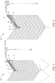
- FIG. 4 and FIG. 5 shows a complete design drawn as a flat pattern (representing how each half 102, 104 would look if pressed flat) in the CAD software.
- Each half 102, 104 consists of two different designs of radial struts (sinusoidal strut 6 and S-shaped strut 2-4) but arrayed multiple times along the length of the stent 100.
- One strut 6 runs directly from longitudinal strut 1 (such as longitudinal strut 106, 108), also referred to as a central strut 1, to a longitudinal strut 5, also referred to as an edge strut 5, at the other end.
- the strut 6 has a sinusoidal shape for enhanced flexibility.
- the other strut 2-4 includes struts 2, 3, and 4 and has an "S" shape as shown in FIG. 4 .
- the "S" shaped strut originates from the longitudinal strut 1, transverses straight as strut 2 towards the other longitudinal strut 5 at which point it turns around and transverses the same length back as strut 3 in parallel to strut 2 and turns back one more time as strut 4 that runs parallel to strut 2 and 3 and finally connects to the other longitudinal strut 5.
- This S-shaped strut 2-4 adds to the overall flexibility of the device 100 and advantageously provides the desired kink resistance that a neurovascular stent is required to possess.
- These two struts (sinusoidal 6 and S-shaped 2-4) repeat themselves (array) multiple times for the remainder of length of the device 100.
- the resulting strut structures of the final assembled stent 100 is illustrated by overlapping the two flat patterns (as if the stent has been flattened) of both parts 102, 104 on top of each other as shown in FIG. 6 .
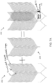
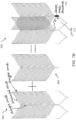
- a stent 200 includes a first half 202 and a second half 204 having sinusoidal longitudinal struts and sinusoidal radial struts as shown by the flat pattern view in FIG. 7A .
- a stent 300 includes a first half 302 and a second half 304 having straight longitudinal struts and sinusoidal radial struts as shown by the flat pattern view in FIG. 7B .
- a stent 400 including a first half 402 and a second half 404 having straight longitudinal struts and straight radial struts as shown by the flat pattern view in FIG. 7C .
- the stent 100 can be constructed using only one half (instead of two halves 102, 104 as above).
- An example of such stent 500 using only one half is shown in FIG. 8 .
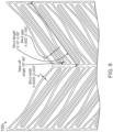
- the longitudinal struts 5 slide over each other as the stent is compressed in radial direction to a smaller diameter thereby resulting in a dense mesh structure 110 as shown in FIG. 9 .
- the length of the struts should be as long as possible.
- FIG. 9 shows a flat pattern view of a part of a stent device such as stent 100 and illustrates exemplary dimensions of stent 100 (e.g., implemented according to any of the examples shown in FIGS. 2-8 ).
- the dimensions of struts of a final assembled stent 100 can be anywhere from 12.7 ⁇ m to 76.2 ⁇ m (0.0005" to 0.003") in width depending upon the degree of flexibility desired.
- the gap between the radial struts can be anywhere from 0.0508 to 2.54 mm (0.002" to 0.100") depending upon the degree of denseness desired.
- the take-off angle of the radial struts from the longitudinal strut can be anywhere from 15° to 90° as shown in FIG. 9 .
- the length of the radial strut can be anywhere from 2.54 to 12.7 mm (0.10" to 0.50") but not limited to this range.
- the length of the stent 100 can be anywhere from 10 mm to 60 mm. However a construction of a stent 100 of length beyond this range is entirely feasible.
- the diameter of the stent 100 can be anywhere from 2mm to 7mm. However, this method of construction is scalable for the diameters greater than 7mm.
- this stent 100 To construct this stent 100, first the flat patterns of each halves 102, 1074 of the stent 100 are drawn using a CAD software, for example AutoCAD.
- the strut width in the flat pattern can be anywhere between 76.2 ⁇ m to 127 ⁇ m (0.0030" to 0.0050").
- the specification of the strut width depends upon the wall thickness of the nickel-titanium hypotube that the stent 100 is cut from.
- the electronic flat patterns are then programmed into a computerized laser-cutting equipment. After the equipment has been programmed, it drives a powerful laser beam along the edges of the design pattern and thereby cuts the exact same pattern from the nickel-titanium hypotube.
- the laser-cut stent 100 goes through a sequence of subsequent processes.
- Some of those include: stress-relief heat treatment at 500°C to remove stresses from the laser-cut parts, microblasting to remove the outside oxide layer, expansion to a larger diameter by shape setting at 500°C, chemical etching and electro-polishing to remove much of material to obtain the final strut width.
- nitinol stents 100 to get a dense mesh has been demonstrated before but only by deploying two finished stents separately, second stent inside the first one.
- the process of stenting an aneurysm in two separate deployments not only increases the clinical risks associated with the deployment but also requires the catheter access through the first deployed stent.
- One or more embodiments of the present disclosure facilitate the features of two overlapped-stents in one stent.
- Advantageous features of one or more embodiments of the present disclosure are the process of assembling the stent 100 using two parts 102, 104 and the process of joining the two parts together at a location such as location 112 as described herein.
- the stent 100 described in one or more embodiments of the present disclosure facilitate a dense mesh across the neck of an aneurysm using only a single deployment hence reducing the clinical risk. Since there is no second deployment involved with this stent 100, it eliminates the requirement of catheter access through the deployed stent.
- the longitudinal struts of the respective parts are aligned and wrapped (e.g., using a radiopaque marker) that could be in the form of a tube such as a platinum marker band as shown in FIG. 10A or a wound coil such as a platinum coil as shown in FIG. 10B .
- a tube such as a platinum marker band may be mechanically crimped prior to filling the inside of the space with the solder as shown in FIG. 12 .
- the tube may be crimped and a solder may not be applied, or the filling of the space with the solder may be performed prior to crimping the tube.
- radiopaque markers platinum or gold material
- additional radiopaque markers may be added at desired locations of the stent 100 using the method of crimping or soldering.
- the stent is then mounted on a delivery system and loaded inside an introducer sheath.
- the stent 100 since the two parts 102, 104 of an assembled stent 100 are free to slide inside one another, the stent 100 exhibits excellent resistance to kinking when deployed inside a tight curve.
- Another advantageous feature of one or more embodiments of the present disclosure is the ease of manufacturability of the stent 100.
Landscapes
- Health & Medical Sciences (AREA)
- Engineering & Computer Science (AREA)
- Biomedical Technology (AREA)
- Heart & Thoracic Surgery (AREA)
- Life Sciences & Earth Sciences (AREA)
- Cardiology (AREA)
- Oral & Maxillofacial Surgery (AREA)
- Transplantation (AREA)
- Veterinary Medicine (AREA)
- Vascular Medicine (AREA)
- Public Health (AREA)
- Animal Behavior & Ethology (AREA)
- General Health & Medical Sciences (AREA)
- Optics & Photonics (AREA)
- Physics & Mathematics (AREA)
- Prostheses (AREA)
- Surgical Instruments (AREA)
Claims (7)
- Stent (100), umfassend:
einen ersten sich in Längsrichtung erstreckenden Zylinder (102) mit einem C-förmigen Querschnitt, wobei der erste Zylinder (102) eine Mehrzahl von ersten Längsstreben (106) und eine Anordnung von ersten radialen Streben umfasst, die sich zwischen den ersten Längsstreben (106) erstrecken; undeinen zweiten, sich in Längsrichtung erstreckenden Zylinder (104) mit einem C-förmigen Querschnitt, wobei der zweite Zylinder (104) eine Mehrzahl von zweiten Längsstreben (108) und eine Anordnung von zweiten radialen Streben umfasst, die sich zwischen den zweiten Längsstreben (108) erstrecken;wobei sich ein Teil des ersten Zylinders (102) und ein Teil des zweiten Zylinders (104) überlappen, um ein dichtes Netz auszubilden, dadurch gekennzeichnet, dass:der erste Zylinder (102) und der zweite Zylinder (104) an einer Verbindungsstelle (112) befestigt sind, die einen Teil der ersten Längsstreben (106) und einen Teil der zweiten Längsstreben (108) umfasst, und dadurch, dassder erste Zylinder (102) und der zweite Zylinder (104) an der Verbindungsstelle (112) befestigt sind, indem ein Rohr oder eine Spule um den Teil der ersten Längsstreben (106) und den Teil der zweiten Längsstreben (106) gewunden wird. - Stent (100) nach Anspruch 1, wobei sich mehr als die Hälfte des ersten Zylinders (102) und mehr als die Hälfte des zweiten Zylinders (104) überlappen, um das dichte Netz (110) auszubilden, und
wobei der erste Zylinder (102) und der zweite Zylinder (104) derart ausgerichtet sind, dass sich eine Öffnung des ersten Zylinders (102) und eine Öffnung des zweiten Zylinders (104) radial auf gegenüberliegenden Seiten des Stents (100) befinden. - Stent (100) nach Anspruch 1, wobei der zweite Zylinder (104) innerhalb des ersten Zylinders (102) angeordnet ist.
- Stent (100) nach Anspruch 1, wobei der erste Zylinder (102) und der zweite Zylinder (104) an der Verbindungsstelle (112) ferner durch ein in dem verwundeten Rohr oder der verwundeten Spule angeordnetes Lot befestigt sind und das Rohr oder die Spule eine röntgendichte Markierung umfasst.
- Stent (100) nach Anspruch 1, wobei die ersten und die zweiten radialen Streben gerade Streben, sinusförmige Streben oder beides umfassen.
- Stent (100) nach Anspruch 1, wobei die ersten und die zweiten Längsstreben (106, 108) jeweils eine Mittelstrebe und zwei Randstreben umfassen und der erste Zylinder (102) und der zweite Zylinder (104) die gleiche Form aufweisen.
- Stent (100) nach Anspruch 1, wobei die ersten und die zweiten Längsstreben (106, 108) S-förmige Streben umfassen, die mit einer entsprechenden Mittelstrebe verbunden sind und sich von dieser in Richtung einer entsprechenden Randstrebe erstrecken, sich biegen, um sich in Richtung der entsprechenden Mittelstrebe zu erstrecken, und sich biegen, um sich in Richtung der entsprechenden Randstrebe zu erstrecken und sich mit dieser zu verbinden, und
wobei ein Abzugswinkel der ersten radialen Streben von einer entsprechenden einen der ersten Längsstreben (106) zwischen 15° und 90° liegt, und wobei ein Abzugswinkel der zweiten radialen Streben von einer entsprechenden einen der zweiten Längsstreben (108) zwischen 15° bis 90° liegt.
Applications Claiming Priority (2)
| Application Number | Priority Date | Filing Date | Title |
|---|---|---|---|
| US201562105432P | 2015-01-20 | 2015-01-20 | |
| PCT/US2016/014191 WO2016118669A1 (en) | 2015-01-20 | 2016-01-20 | Self-expandable scaffolding device for the treatment of aneurysms |
Publications (3)
| Publication Number | Publication Date |
|---|---|
| EP3247316A1 EP3247316A1 (de) | 2017-11-29 |
| EP3247316A4 EP3247316A4 (de) | 2019-01-16 |
| EP3247316B1 true EP3247316B1 (de) | 2024-03-06 |
Family
ID=56417711
Family Applications (1)
| Application Number | Title | Priority Date | Filing Date |
|---|---|---|---|
| EP16740711.3A Active EP3247316B1 (de) | 2015-01-20 | 2016-01-20 | Vorrichtung mit selbstausdehnbarem gerüst zur behandlung von aneurysmen |
Country Status (3)
| Country | Link |
|---|---|
| US (2) | US10507123B2 (de) |
| EP (1) | EP3247316B1 (de) |
| WO (1) | WO2016118669A1 (de) |
Families Citing this family (5)
| Publication number | Priority date | Publication date | Assignee | Title |
|---|---|---|---|---|
| EP3247316B1 (de) * | 2015-01-20 | 2024-03-06 | Monarch Biosciences, Inc. | Vorrichtung mit selbstausdehnbarem gerüst zur behandlung von aneurysmen |
| KR101821746B1 (ko) | 2016-08-24 | 2018-01-24 | 주식회사 엠아이텍 | 약물방출형 생분해성 스텐트 |
| DE102018000966A1 (de) * | 2018-02-07 | 2019-08-22 | Universität Zu Köln | Neuralhülle |
| US20220151619A1 (en) * | 2019-03-11 | 2022-05-19 | The Board Of Supervisors Of Louisiana State University And Agricultural And Mechanical College | Anastomosing stent and methods of use |
| CN114788747A (zh) * | 2021-12-07 | 2022-07-26 | 武汉拓扑转化医学研究中心有限公司 | 一种脑血管瘤血流导向装置 |
Family Cites Families (23)
| Publication number | Priority date | Publication date | Assignee | Title |
|---|---|---|---|---|
| US4877030A (en) * | 1988-02-02 | 1989-10-31 | Andreas Beck | Device for the widening of blood vessels |
| US5007926A (en) * | 1989-02-24 | 1991-04-16 | The Trustees Of The University Of Pennsylvania | Expandable transluminally implantable tubular prosthesis |
| FR2727854A1 (fr) * | 1994-12-09 | 1996-06-14 | Jean Claude Sgro | Endoprothese autoexpansible |
| US20020173839A1 (en) * | 1998-07-24 | 2002-11-21 | Leopold Eric W. | Intravascular flow modifier and reinforcement device with connected segments |
| AU2001296716A1 (en) * | 2000-10-13 | 2002-04-22 | Rex Medical, Lp | Covered stents with side branch |
| US20080140172A1 (en) * | 2004-12-13 | 2008-06-12 | Robert Hunt Carpenter | Multi-Wall Expandable Device Capable Of Drug Delivery Related Applications |
| US7815674B1 (en) * | 2005-07-27 | 2010-10-19 | Ragazzo John R | Self-expanding stent system |
| WO2007117645A2 (en) * | 2006-04-07 | 2007-10-18 | Penumbra, Inc. | Aneurysm occlusion system and method |
| US20140163664A1 (en) * | 2006-11-21 | 2014-06-12 | David S. Goldsmith | Integrated system for the ballistic and nonballistic infixion and retrieval of implants with or without drug targeting |
| US20090105806A1 (en) * | 2007-10-23 | 2009-04-23 | Endologix, Inc | Stent |
| AU2009213154A1 (en) * | 2008-02-15 | 2009-08-20 | Femoralis, Llc | Peripheral overlap stent |
| US9427302B2 (en) * | 2009-04-09 | 2016-08-30 | Medtronic Vascular, Inc. | Stent having a C-shaped body section for use in a bifurcation |
| US20110276125A1 (en) * | 2010-05-05 | 2011-11-10 | Walker Jeffrey P | Medical Devices, Methods of Producing Medical Devices, and Projection Photolithography Apparatus for Producing Medical Devices |
| DE102011009372B3 (de) | 2011-01-25 | 2012-07-12 | Acandis Gmbh & Co. Kg | Medizinische Vorrichtung mit einer Gitterstruktur und ein Behandlungssystem mit einer derartigen Gitterstruktur |
| US8951298B2 (en) * | 2011-06-21 | 2015-02-10 | Endospan Ltd. | Endovascular system with circumferentially-overlapping stent-grafts |
| DE102012101294A1 (de) | 2012-02-17 | 2013-08-22 | Acandis Gmbh & Co. Kg | Medizinsche Vorrichtung |
| EP3156006B1 (de) * | 2012-03-16 | 2022-05-18 | Terumo Corporation | Stent und stentfreisetzungssystem |
| JP5921682B2 (ja) * | 2012-06-18 | 2016-05-24 | 株式会社パイオラックスメディカルデバイス | ステント |
| US20140180377A1 (en) * | 2012-12-20 | 2014-06-26 | Penumbra, Inc. | Aneurysm occlusion system and method |
| WO2014105873A1 (en) * | 2012-12-26 | 2014-07-03 | Stryker Corporation | Multilayer stent |
| US20160006701A1 (en) * | 2013-04-03 | 2016-01-07 | Telefonaktiebolaget Lm Ericsson (Publ) | Method of and a device handling charging data in an ip-based network |
| US20160067071A1 (en) * | 2013-04-24 | 2016-03-10 | Trustees Of Tufts College | Bioresorbable biopolymer stent |
| EP3247316B1 (de) * | 2015-01-20 | 2024-03-06 | Monarch Biosciences, Inc. | Vorrichtung mit selbstausdehnbarem gerüst zur behandlung von aneurysmen |
-
2016
- 2016-01-20 EP EP16740711.3A patent/EP3247316B1/de active Active
- 2016-01-20 WO PCT/US2016/014191 patent/WO2016118669A1/en not_active Ceased
-
2017
- 2017-07-20 US US15/655,674 patent/US10507123B2/en active Active
-
2019
- 2019-12-16 US US16/716,373 patent/US11413171B2/en active Active
Also Published As
| Publication number | Publication date |
|---|---|
| US10507123B2 (en) | 2019-12-17 |
| WO2016118669A1 (en) | 2016-07-28 |
| US11413171B2 (en) | 2022-08-16 |
| US20170348119A1 (en) | 2017-12-07 |
| EP3247316A4 (de) | 2019-01-16 |
| US20200253755A1 (en) | 2020-08-13 |
| EP3247316A1 (de) | 2017-11-29 |
Similar Documents
| Publication | Publication Date | Title |
|---|---|---|
| US11413171B2 (en) | Self-expandable scaffolding device for the treatment of aneurysms | |
| EP3448270B1 (de) | Vorrichtungen zur behandlung von vaskulären aneurysmen | |
| EP3244843B1 (de) | Stent | |
| AU2018217310B2 (en) | Variable porosity intra vascular implant manufacturing method | |
| CA2773100C (en) | Systems and methods for enclosing an anatomical opening | |
| CN108882986B (zh) | 血管流动转向装置 | |
| CN111936063B (zh) | 利用薄膜镍钛诺箔的血管闭塞装置 | |
| JP6513859B2 (ja) | マーカーを有する編組拡張リング | |
| EP2004101A2 (de) | System und verfahren für aneurysmaverschluss | |
| JP2025105859A (ja) | 二又ステントグラフト、ステント、および方法 | |
| KR20200081260A (ko) | 하나 이상의 확장 링을 갖는 편조 스텐트 시스템 | |
| US11123206B2 (en) | Kink-resistant stent devices and related methods | |
| AU2010289240B2 (en) | Systems and methods for enclosing an anatomical opening |
Legal Events
| Date | Code | Title | Description |
|---|---|---|---|
| STAA | Information on the status of an ep patent application or granted ep patent |
Free format text: STATUS: THE INTERNATIONAL PUBLICATION HAS BEEN MADE |
|
| PUAI | Public reference made under article 153(3) epc to a published international application that has entered the european phase |
Free format text: ORIGINAL CODE: 0009012 |
|
| STAA | Information on the status of an ep patent application or granted ep patent |
Free format text: STATUS: REQUEST FOR EXAMINATION WAS MADE |
|
| 17P | Request for examination filed |
Effective date: 20170725 |
|
| AK | Designated contracting states |
Kind code of ref document: A1 Designated state(s): AL AT BE BG CH CY CZ DE DK EE ES FI FR GB GR HR HU IE IS IT LI LT LU LV MC MK MT NL NO PL PT RO RS SE SI SK SM TR |
|
| AX | Request for extension of the european patent |
Extension state: BA ME |
|
| DAV | Request for validation of the european patent (deleted) | ||
| DAX | Request for extension of the european patent (deleted) | ||
| RIC1 | Information provided on ipc code assigned before grant |
Ipc: A61F 2/07 20130101ALI20180827BHEP Ipc: A61F 2/852 20130101ALI20180827BHEP Ipc: A61F 2/82 20130101AFI20180827BHEP |
|
| A4 | Supplementary search report drawn up and despatched |
Effective date: 20181217 |
|
| RIC1 | Information provided on ipc code assigned before grant |
Ipc: A61F 2/852 20130101ALI20181211BHEP Ipc: A61F 2/82 20130101AFI20181211BHEP Ipc: A61F 2/07 20130101ALI20181211BHEP |
|
| GRAP | Despatch of communication of intention to grant a patent |
Free format text: ORIGINAL CODE: EPIDOSNIGR1 |
|
| STAA | Information on the status of an ep patent application or granted ep patent |
Free format text: STATUS: GRANT OF PATENT IS INTENDED |
|
| INTG | Intention to grant announced |
Effective date: 20230425 |
|
| RAP3 | Party data changed (applicant data changed or rights of an application transferred) |
Owner name: MONARCH BIOSCIENCES, INC. |
|
| GRAJ | Information related to disapproval of communication of intention to grant by the applicant or resumption of examination proceedings by the epo deleted |
Free format text: ORIGINAL CODE: EPIDOSDIGR1 |
|
| STAA | Information on the status of an ep patent application or granted ep patent |
Free format text: STATUS: REQUEST FOR EXAMINATION WAS MADE |
|
| GRAP | Despatch of communication of intention to grant a patent |
Free format text: ORIGINAL CODE: EPIDOSNIGR1 |
|
| STAA | Information on the status of an ep patent application or granted ep patent |
Free format text: STATUS: GRANT OF PATENT IS INTENDED |
|
| INTC | Intention to grant announced (deleted) | ||
| INTG | Intention to grant announced |
Effective date: 20230830 |
|
| GRAS | Grant fee paid |
Free format text: ORIGINAL CODE: EPIDOSNIGR3 |
|
| RAP3 | Party data changed (applicant data changed or rights of an application transferred) |
Owner name: MONARCH BIOSCIENCES, INC. |
|
| GRAA | (expected) grant |
Free format text: ORIGINAL CODE: 0009210 |
|
| STAA | Information on the status of an ep patent application or granted ep patent |
Free format text: STATUS: THE PATENT HAS BEEN GRANTED |
|
| AK | Designated contracting states |
Kind code of ref document: B1 Designated state(s): AL AT BE BG CH CY CZ DE DK EE ES FI FR GB GR HR HU IE IS IT LI LT LU LV MC MK MT NL NO PL PT RO RS SE SI SK SM TR |
|
| REG | Reference to a national code |
Ref country code: GB Ref legal event code: FG4D |
|
| REG | Reference to a national code |
Ref country code: CH Ref legal event code: EP |
|
| REG | Reference to a national code |
Ref country code: IE Ref legal event code: FG4D |
|
| REG | Reference to a national code |
Ref country code: DE Ref legal event code: R096 Ref document number: 602016086149 Country of ref document: DE |
|
| REG | Reference to a national code |
Ref country code: LT Ref legal event code: MG9D |
|
| PG25 | Lapsed in a contracting state [announced via postgrant information from national office to epo] |
Ref country code: LT Free format text: LAPSE BECAUSE OF FAILURE TO SUBMIT A TRANSLATION OF THE DESCRIPTION OR TO PAY THE FEE WITHIN THE PRESCRIBED TIME-LIMIT Effective date: 20240306 |
|
| REG | Reference to a national code |
Ref country code: NL Ref legal event code: MP Effective date: 20240306 |
|
| PG25 | Lapsed in a contracting state [announced via postgrant information from national office to epo] |
Ref country code: GR Free format text: LAPSE BECAUSE OF FAILURE TO SUBMIT A TRANSLATION OF THE DESCRIPTION OR TO PAY THE FEE WITHIN THE PRESCRIBED TIME-LIMIT Effective date: 20240607 |
|
| PG25 | Lapsed in a contracting state [announced via postgrant information from national office to epo] |
Ref country code: HR Free format text: LAPSE BECAUSE OF FAILURE TO SUBMIT A TRANSLATION OF THE DESCRIPTION OR TO PAY THE FEE WITHIN THE PRESCRIBED TIME-LIMIT Effective date: 20240306 Ref country code: RS Free format text: LAPSE BECAUSE OF FAILURE TO SUBMIT A TRANSLATION OF THE DESCRIPTION OR TO PAY THE FEE WITHIN THE PRESCRIBED TIME-LIMIT Effective date: 20240606 |
|
| PG25 | Lapsed in a contracting state [announced via postgrant information from national office to epo] |
Ref country code: ES Free format text: LAPSE BECAUSE OF FAILURE TO SUBMIT A TRANSLATION OF THE DESCRIPTION OR TO PAY THE FEE WITHIN THE PRESCRIBED TIME-LIMIT Effective date: 20240306 |
|
| PG25 | Lapsed in a contracting state [announced via postgrant information from national office to epo] |
Ref country code: RS Free format text: LAPSE BECAUSE OF FAILURE TO SUBMIT A TRANSLATION OF THE DESCRIPTION OR TO PAY THE FEE WITHIN THE PRESCRIBED TIME-LIMIT Effective date: 20240606 Ref country code: NO Free format text: LAPSE BECAUSE OF FAILURE TO SUBMIT A TRANSLATION OF THE DESCRIPTION OR TO PAY THE FEE WITHIN THE PRESCRIBED TIME-LIMIT Effective date: 20240606 Ref country code: LT Free format text: LAPSE BECAUSE OF FAILURE TO SUBMIT A TRANSLATION OF THE DESCRIPTION OR TO PAY THE FEE WITHIN THE PRESCRIBED TIME-LIMIT Effective date: 20240306 Ref country code: HR Free format text: LAPSE BECAUSE OF FAILURE TO SUBMIT A TRANSLATION OF THE DESCRIPTION OR TO PAY THE FEE WITHIN THE PRESCRIBED TIME-LIMIT Effective date: 20240306 Ref country code: GR Free format text: LAPSE BECAUSE OF FAILURE TO SUBMIT A TRANSLATION OF THE DESCRIPTION OR TO PAY THE FEE WITHIN THE PRESCRIBED TIME-LIMIT Effective date: 20240607 Ref country code: FI Free format text: LAPSE BECAUSE OF FAILURE TO SUBMIT A TRANSLATION OF THE DESCRIPTION OR TO PAY THE FEE WITHIN THE PRESCRIBED TIME-LIMIT Effective date: 20240306 Ref country code: ES Free format text: LAPSE BECAUSE OF FAILURE TO SUBMIT A TRANSLATION OF THE DESCRIPTION OR TO PAY THE FEE WITHIN THE PRESCRIBED TIME-LIMIT Effective date: 20240306 Ref country code: BG Free format text: LAPSE BECAUSE OF FAILURE TO SUBMIT A TRANSLATION OF THE DESCRIPTION OR TO PAY THE FEE WITHIN THE PRESCRIBED TIME-LIMIT Effective date: 20240306 |
|
| REG | Reference to a national code |
Ref country code: AT Ref legal event code: MK05 Ref document number: 1662749 Country of ref document: AT Kind code of ref document: T Effective date: 20240306 |
|
| PG25 | Lapsed in a contracting state [announced via postgrant information from national office to epo] |
Ref country code: SE Free format text: LAPSE BECAUSE OF FAILURE TO SUBMIT A TRANSLATION OF THE DESCRIPTION OR TO PAY THE FEE WITHIN THE PRESCRIBED TIME-LIMIT Effective date: 20240306 Ref country code: LV Free format text: LAPSE BECAUSE OF FAILURE TO SUBMIT A TRANSLATION OF THE DESCRIPTION OR TO PAY THE FEE WITHIN THE PRESCRIBED TIME-LIMIT Effective date: 20240306 |
|
| PG25 | Lapsed in a contracting state [announced via postgrant information from national office to epo] |
Ref country code: NL Free format text: LAPSE BECAUSE OF FAILURE TO SUBMIT A TRANSLATION OF THE DESCRIPTION OR TO PAY THE FEE WITHIN THE PRESCRIBED TIME-LIMIT Effective date: 20240306 |
|
| PG25 | Lapsed in a contracting state [announced via postgrant information from national office to epo] |
Ref country code: NL Free format text: LAPSE BECAUSE OF FAILURE TO SUBMIT A TRANSLATION OF THE DESCRIPTION OR TO PAY THE FEE WITHIN THE PRESCRIBED TIME-LIMIT Effective date: 20240306 |
|
| PG25 | Lapsed in a contracting state [announced via postgrant information from national office to epo] |
Ref country code: IS Free format text: LAPSE BECAUSE OF FAILURE TO SUBMIT A TRANSLATION OF THE DESCRIPTION OR TO PAY THE FEE WITHIN THE PRESCRIBED TIME-LIMIT Effective date: 20240706 |
|
| PG25 | Lapsed in a contracting state [announced via postgrant information from national office to epo] |
Ref country code: PT Free format text: LAPSE BECAUSE OF FAILURE TO SUBMIT A TRANSLATION OF THE DESCRIPTION OR TO PAY THE FEE WITHIN THE PRESCRIBED TIME-LIMIT Effective date: 20240708 Ref country code: SM Free format text: LAPSE BECAUSE OF FAILURE TO SUBMIT A TRANSLATION OF THE DESCRIPTION OR TO PAY THE FEE WITHIN THE PRESCRIBED TIME-LIMIT Effective date: 20240306 |
|
| PG25 | Lapsed in a contracting state [announced via postgrant information from national office to epo] |
Ref country code: CZ Free format text: LAPSE BECAUSE OF FAILURE TO SUBMIT A TRANSLATION OF THE DESCRIPTION OR TO PAY THE FEE WITHIN THE PRESCRIBED TIME-LIMIT Effective date: 20240306 Ref country code: EE Free format text: LAPSE BECAUSE OF FAILURE TO SUBMIT A TRANSLATION OF THE DESCRIPTION OR TO PAY THE FEE WITHIN THE PRESCRIBED TIME-LIMIT Effective date: 20240306 |
|
| PG25 | Lapsed in a contracting state [announced via postgrant information from national office to epo] |
Ref country code: AT Free format text: LAPSE BECAUSE OF FAILURE TO SUBMIT A TRANSLATION OF THE DESCRIPTION OR TO PAY THE FEE WITHIN THE PRESCRIBED TIME-LIMIT Effective date: 20240306 |
|
| PG25 | Lapsed in a contracting state [announced via postgrant information from national office to epo] |
Ref country code: PL Free format text: LAPSE BECAUSE OF FAILURE TO SUBMIT A TRANSLATION OF THE DESCRIPTION OR TO PAY THE FEE WITHIN THE PRESCRIBED TIME-LIMIT Effective date: 20240306 |
|
| PG25 | Lapsed in a contracting state [announced via postgrant information from national office to epo] |
Ref country code: SK Free format text: LAPSE BECAUSE OF FAILURE TO SUBMIT A TRANSLATION OF THE DESCRIPTION OR TO PAY THE FEE WITHIN THE PRESCRIBED TIME-LIMIT Effective date: 20240306 |
|
| PG25 | Lapsed in a contracting state [announced via postgrant information from national office to epo] |
Ref country code: SM Free format text: LAPSE BECAUSE OF FAILURE TO SUBMIT A TRANSLATION OF THE DESCRIPTION OR TO PAY THE FEE WITHIN THE PRESCRIBED TIME-LIMIT Effective date: 20240306 Ref country code: SK Free format text: LAPSE BECAUSE OF FAILURE TO SUBMIT A TRANSLATION OF THE DESCRIPTION OR TO PAY THE FEE WITHIN THE PRESCRIBED TIME-LIMIT Effective date: 20240306 Ref country code: RO Free format text: LAPSE BECAUSE OF FAILURE TO SUBMIT A TRANSLATION OF THE DESCRIPTION OR TO PAY THE FEE WITHIN THE PRESCRIBED TIME-LIMIT Effective date: 20240306 Ref country code: PT Free format text: LAPSE BECAUSE OF FAILURE TO SUBMIT A TRANSLATION OF THE DESCRIPTION OR TO PAY THE FEE WITHIN THE PRESCRIBED TIME-LIMIT Effective date: 20240708 Ref country code: PL Free format text: LAPSE BECAUSE OF FAILURE TO SUBMIT A TRANSLATION OF THE DESCRIPTION OR TO PAY THE FEE WITHIN THE PRESCRIBED TIME-LIMIT Effective date: 20240306 Ref country code: IS Free format text: LAPSE BECAUSE OF FAILURE TO SUBMIT A TRANSLATION OF THE DESCRIPTION OR TO PAY THE FEE WITHIN THE PRESCRIBED TIME-LIMIT Effective date: 20240706 Ref country code: EE Free format text: LAPSE BECAUSE OF FAILURE TO SUBMIT A TRANSLATION OF THE DESCRIPTION OR TO PAY THE FEE WITHIN THE PRESCRIBED TIME-LIMIT Effective date: 20240306 Ref country code: CZ Free format text: LAPSE BECAUSE OF FAILURE TO SUBMIT A TRANSLATION OF THE DESCRIPTION OR TO PAY THE FEE WITHIN THE PRESCRIBED TIME-LIMIT Effective date: 20240306 Ref country code: AT Free format text: LAPSE BECAUSE OF FAILURE TO SUBMIT A TRANSLATION OF THE DESCRIPTION OR TO PAY THE FEE WITHIN THE PRESCRIBED TIME-LIMIT Effective date: 20240306 |
|
| PG25 | Lapsed in a contracting state [announced via postgrant information from national office to epo] |
Ref country code: IT Free format text: LAPSE BECAUSE OF FAILURE TO SUBMIT A TRANSLATION OF THE DESCRIPTION OR TO PAY THE FEE WITHIN THE PRESCRIBED TIME-LIMIT Effective date: 20240306 |
|
| REG | Reference to a national code |
Ref country code: DE Ref legal event code: R097 Ref document number: 602016086149 Country of ref document: DE |
|
| PG25 | Lapsed in a contracting state [announced via postgrant information from national office to epo] |
Ref country code: IT Free format text: LAPSE BECAUSE OF FAILURE TO SUBMIT A TRANSLATION OF THE DESCRIPTION OR TO PAY THE FEE WITHIN THE PRESCRIBED TIME-LIMIT Effective date: 20240306 |
|
| PLBE | No opposition filed within time limit |
Free format text: ORIGINAL CODE: 0009261 |
|
| STAA | Information on the status of an ep patent application or granted ep patent |
Free format text: STATUS: NO OPPOSITION FILED WITHIN TIME LIMIT |
|
| PG25 | Lapsed in a contracting state [announced via postgrant information from national office to epo] |
Ref country code: DK Free format text: LAPSE BECAUSE OF FAILURE TO SUBMIT A TRANSLATION OF THE DESCRIPTION OR TO PAY THE FEE WITHIN THE PRESCRIBED TIME-LIMIT Effective date: 20240306 |
|
| PG25 | Lapsed in a contracting state [announced via postgrant information from national office to epo] |
Ref country code: DK Free format text: LAPSE BECAUSE OF FAILURE TO SUBMIT A TRANSLATION OF THE DESCRIPTION OR TO PAY THE FEE WITHIN THE PRESCRIBED TIME-LIMIT Effective date: 20240306 |
|
| 26N | No opposition filed |
Effective date: 20241209 |
|
| PG25 | Lapsed in a contracting state [announced via postgrant information from national office to epo] |
Ref country code: SI Free format text: LAPSE BECAUSE OF FAILURE TO SUBMIT A TRANSLATION OF THE DESCRIPTION OR TO PAY THE FEE WITHIN THE PRESCRIBED TIME-LIMIT Effective date: 20240306 |
|
| REG | Reference to a national code |
Ref country code: CH Ref legal event code: PL |
|
| PG25 | Lapsed in a contracting state [announced via postgrant information from national office to epo] |
Ref country code: MC Free format text: LAPSE BECAUSE OF FAILURE TO SUBMIT A TRANSLATION OF THE DESCRIPTION OR TO PAY THE FEE WITHIN THE PRESCRIBED TIME-LIMIT Effective date: 20240306 Ref country code: LU Free format text: LAPSE BECAUSE OF NON-PAYMENT OF DUE FEES Effective date: 20250120 |
|
| PG25 | Lapsed in a contracting state [announced via postgrant information from national office to epo] |
Ref country code: BE Free format text: LAPSE BECAUSE OF NON-PAYMENT OF DUE FEES Effective date: 20250131 |
|
| PG25 | Lapsed in a contracting state [announced via postgrant information from national office to epo] |
Ref country code: CH Free format text: LAPSE BECAUSE OF NON-PAYMENT OF DUE FEES Effective date: 20250131 |
|
| REG | Reference to a national code |
Ref country code: BE Ref legal event code: MM Effective date: 20250131 |
|
| PG25 | Lapsed in a contracting state [announced via postgrant information from national office to epo] |
Ref country code: IE Free format text: LAPSE BECAUSE OF NON-PAYMENT OF DUE FEES Effective date: 20250120 |
|
| PGFP | Annual fee paid to national office [announced via postgrant information from national office to epo] |
Ref country code: GB Payment date: 20260127 Year of fee payment: 11 |
|
| PGFP | Annual fee paid to national office [announced via postgrant information from national office to epo] |
Ref country code: DE Payment date: 20260128 Year of fee payment: 11 |
|
| PGFP | Annual fee paid to national office [announced via postgrant information from national office to epo] |
Ref country code: FR Payment date: 20260126 Year of fee payment: 11 |