EP3246648B1 - Dispositif de refroidissement à caloduc pulsé - Google Patents
Dispositif de refroidissement à caloduc pulsé Download PDFInfo
- Publication number
- EP3246648B1 EP3246648B1 EP17305564.1A EP17305564A EP3246648B1 EP 3246648 B1 EP3246648 B1 EP 3246648B1 EP 17305564 A EP17305564 A EP 17305564A EP 3246648 B1 EP3246648 B1 EP 3246648B1
- Authority
- EP
- European Patent Office
- Prior art keywords
- cooling device
- portions
- side edge
- support
- heat
- Prior art date
- Legal status (The legal status is an assumption and is not a legal conclusion. Google has not performed a legal analysis and makes no representation as to the accuracy of the status listed.)
- Active
Links
Images


Classifications
-
- F—MECHANICAL ENGINEERING; LIGHTING; HEATING; WEAPONS; BLASTING
- F28—HEAT EXCHANGE IN GENERAL
- F28D—HEAT-EXCHANGE APPARATUS, NOT PROVIDED FOR IN ANOTHER SUBCLASS, IN WHICH THE HEAT-EXCHANGE MEDIA DO NOT COME INTO DIRECT CONTACT
- F28D15/00—Heat-exchange apparatus with the intermediate heat-transfer medium in closed tubes passing into or through the conduit walls ; Heat-exchange apparatus employing intermediate heat-transfer medium or bodies
- F28D15/02—Heat-exchange apparatus with the intermediate heat-transfer medium in closed tubes passing into or through the conduit walls ; Heat-exchange apparatus employing intermediate heat-transfer medium or bodies in which the medium condenses and evaporates, e.g. heat pipes
-
- F—MECHANICAL ENGINEERING; LIGHTING; HEATING; WEAPONS; BLASTING
- F21—LIGHTING
- F21V—FUNCTIONAL FEATURES OR DETAILS OF LIGHTING DEVICES OR SYSTEMS THEREOF; STRUCTURAL COMBINATIONS OF LIGHTING DEVICES WITH OTHER ARTICLES, NOT OTHERWISE PROVIDED FOR
- F21V29/00—Protecting lighting devices from thermal damage; Cooling or heating arrangements specially adapted for lighting devices or systems
- F21V29/50—Cooling arrangements
- F21V29/51—Cooling arrangements using condensation or evaporation of a fluid, e.g. heat pipes
-
- F—MECHANICAL ENGINEERING; LIGHTING; HEATING; WEAPONS; BLASTING
- F21—LIGHTING
- F21V—FUNCTIONAL FEATURES OR DETAILS OF LIGHTING DEVICES OR SYSTEMS THEREOF; STRUCTURAL COMBINATIONS OF LIGHTING DEVICES WITH OTHER ARTICLES, NOT OTHERWISE PROVIDED FOR
- F21V29/00—Protecting lighting devices from thermal damage; Cooling or heating arrangements specially adapted for lighting devices or systems
- F21V29/50—Cooling arrangements
- F21V29/70—Cooling arrangements characterised by passive heat-dissipating elements, e.g. heat-sinks
- F21V29/74—Cooling arrangements characterised by passive heat-dissipating elements, e.g. heat-sinks with fins or blades
-
- F—MECHANICAL ENGINEERING; LIGHTING; HEATING; WEAPONS; BLASTING
- F28—HEAT EXCHANGE IN GENERAL
- F28D—HEAT-EXCHANGE APPARATUS, NOT PROVIDED FOR IN ANOTHER SUBCLASS, IN WHICH THE HEAT-EXCHANGE MEDIA DO NOT COME INTO DIRECT CONTACT
- F28D15/00—Heat-exchange apparatus with the intermediate heat-transfer medium in closed tubes passing into or through the conduit walls ; Heat-exchange apparatus employing intermediate heat-transfer medium or bodies
- F28D15/02—Heat-exchange apparatus with the intermediate heat-transfer medium in closed tubes passing into or through the conduit walls ; Heat-exchange apparatus employing intermediate heat-transfer medium or bodies in which the medium condenses and evaporates, e.g. heat pipes
- F28D15/0233—Heat-exchange apparatus with the intermediate heat-transfer medium in closed tubes passing into or through the conduit walls ; Heat-exchange apparatus employing intermediate heat-transfer medium or bodies in which the medium condenses and evaporates, e.g. heat pipes the conduits having a particular shape, e.g. non-circular cross-section, annular
-
- F—MECHANICAL ENGINEERING; LIGHTING; HEATING; WEAPONS; BLASTING
- F28—HEAT EXCHANGE IN GENERAL
- F28D—HEAT-EXCHANGE APPARATUS, NOT PROVIDED FOR IN ANOTHER SUBCLASS, IN WHICH THE HEAT-EXCHANGE MEDIA DO NOT COME INTO DIRECT CONTACT
- F28D15/00—Heat-exchange apparatus with the intermediate heat-transfer medium in closed tubes passing into or through the conduit walls ; Heat-exchange apparatus employing intermediate heat-transfer medium or bodies
- F28D15/02—Heat-exchange apparatus with the intermediate heat-transfer medium in closed tubes passing into or through the conduit walls ; Heat-exchange apparatus employing intermediate heat-transfer medium or bodies in which the medium condenses and evaporates, e.g. heat pipes
- F28D15/0275—Arrangements for coupling heat-pipes together or with other structures, e.g. with base blocks; Heat pipe cores
-
- F—MECHANICAL ENGINEERING; LIGHTING; HEATING; WEAPONS; BLASTING
- F21—LIGHTING
- F21Y—INDEXING SCHEME ASSOCIATED WITH SUBCLASSES F21K, F21L, F21S and F21V, RELATING TO THE FORM OR THE KIND OF THE LIGHT SOURCES OR OF THE COLOUR OF THE LIGHT EMITTED
- F21Y2115/00—Light-generating elements of semiconductor light sources
- F21Y2115/10—Light-emitting diodes [LED]
Definitions
- the present application relates to a passive cooling device capable of cooling a heat source comprising electronic and / or electrical components.
- the device uses an oscillating heat pipe in which a heat transfer fluid can circulate in a pulsed manner under the effect of heat.
- a cooling system 12 is used to cool an electronic circuit equipped with light-emitting diodes. More specifically, as represented in figure 1 , the cooling system comprises an oscillating heat pipe 11 comprising a tube in which a heat transfer fluid circulates in a pulsed manner.
- the tube is a multiport extruded tube comprising channels parallel to each other and stacked in a direction normal to a heat conduction element 13 interposed between the tube and the electronic circuit.
- the tube has the general shape of a ribbon forming a coil extending along the conduction element 13.
- the oscillating heat pipe comprises a hot part located below the conduction element 13 and cold parts located in lateral zones of the coil, disposed on either side of the hot part.
- the heat conduction element 13 transmits the heat produced by the electronic circuit to the hot parts of the heat pipe.
- the heat is then transported by the oscillations of the heat transfer fluid to the cold zones.
- the cold zones then dissipate the heat to the environment by a phenomenon of convection with the ambient air.
- the performance of the cooling device depends directly on this convection phenomenon.
- the document FR3007122A1 proposes the use of heat exchange fins 15 placed between the coils of the coil which are formed by the tube (see figure 2 ). This effective solution nevertheless has the disadvantages of making the manufacture of the device more complex and of increasing its bulk.
- means for moving the ambient air can be used to establish a forced convection of air at the cold areas.
- This solution has the disadvantage of the use of fans that consume energy and in turn produce heat.
- a fan failure significantly degrades the capabilities of the device.
- the operating time of a light emitting diode is much higher than the operating time of a fan. Therefore, it is necessary to perform regular checks of their proper operation to ensure that the light source is properly cooled to prevent damage to said source. This is why the use of a fan is not an ideal solution for cooling a cooling device.
- the solutions currently proposed are therefore not fully satisfactory.
- the present application therefore aims to propose a cooling device solving the disadvantages mentioned above.
- the present application aims to provide a cooling device comprising a pulsed heat pipe less expensive to manufacture, more economical and more reliable use, with increased performance for the same volume given the state of the technical.
- the present application proposes a cooling device capable of cooling a heat source comprising electronic and / or electrical components.
- the cooling system is characterized in that it comprises a support composed of a first plate joined to a second plate.
- the first plate has two large opposite faces interconnected by means of lateral edges.
- the first plate comprises at a first large face at least one groove extending between a first lateral edge and a second opposite lateral edge, the groove comprises first portions parallel or substantially parallel to the first side edge connected by seconds.
- the groove is covered by the second plate so as to form an oscillating heat pipe in which circulates a heat transfer fluid state change.
- the carrier is bent to form at least one conduit extending from the first side edge to the second opposite side edge, and at least one duct is partially closed by a plate in contact with the first lateral edge so as to allow a natural flow of the ambient air in the duct or ducts formed by the support.
- the oscillating heat pipe is thus delimited by the first and the second plate, and not by a tube as described by the document FR3007122A1 .
- This difference allows the heat transported by the heat transfer fluid to diffuse inside the two plates to the two large opposite faces of the support.
- This diffusion phenomenon makes it possible to distribute the heat on all the faces of the support in order to advantageously increase the heat exchange surface between the cooling device and the ambient air, without it being necessary for this to be used. fins of heat exchange.
- the duct or ducts formed by the support promote a phenomenon of natural convection of the ambient air along the support, without it being necessary to use a fan.
- the present application advantageously makes it possible to cool more efficiently and more simply a heat source more economically, for the same volume of occupation, compared with the state of the art.
- At least one duct delimited by the support has a height favoring a natural convection movement of the ambient air in the duct.
- height is meant a distance along an axis normal to the plate closing a conduit.
- the height of a duct is chosen so that the pressure differential between the inside and the outside of the duct is greater than the phenomenon of pressure drops experienced by the air flowing in the duct. The value of the height therefore depends on the power of the heat source and the ambient temperature.
- the first edge and the second lateral edge of the first plate are separated by a distance of between 1 mm and 500 mm, preferably between 10 mm and 500 mm.
- the phenomenon of pressure losses mentioned above also depends on the distance between two adjacent turns delimited by the support, that is to say, the width duct formed by said turns.
- the term "width" means a distance along an axis normal to the height of the conduit.
- the distance between two adjacent turns may be between 1mm and 300mm.
- the value of this distance may also vary depending on the power of the heat source, the ambient temperature and the desired compactness of the device.
- the total length of the first portions is greater than the total length of the second portions.
- the gap between two adjacent first portions of a groove is selected so as to allow homogeneous diffusion of heat at the surface defining a conduit.
- the duct surface tends to have a substantially homogeneous temperature which favors a greater flow of air in the ducts.
- the difference between two adjacent first portions depends in particular on the amount of heat to be dissipated, the dimensions of the grooves and the thermal conductivity coefficient of the plates.
- the difference between two adjacent first portions may be between 1mm and 50mm, preferably between 1mm and 30mm. The skilled person may consider other values according to the parameters mentioned above.
- the gap between two adjacent first portions may vary between the first side face and the second side face, so that the oscillating heat pipe can diffuse a greater amount of heat at the portions of the support which are the further away from the thermal conduction plate.
- This embodiment is particularly advantageous when the coefficient of thermal conductivity of the support is low.
- the gaps between the first sections can be adapted to compensate for a limited diffusion of heat in the support.
- the length of the second portions is less than 30 mm.
- the second portions may be longer than the gap between two adjacent first portions so as to form curved portions.
- the second portions have a radius of curvature favoring the flow of the coolant in the oscillating heat pipe.
- the radius of curvature can be between 1mm and 50mm, preferably between 5mm and 25mm.
- the diameter of the heat pipe is chosen so that the capillary forces exerted on the phase change fluid are greater than the forces exerted on said fluid by the gravity.
- the diameter of the heat pipe depends on the characteristics of the coolant, for example its viscosity.
- the hydraulic diameter of the passage section of the heat pipe may be greater than 1 mm and / or less than a diameter equivalent to a number of Eötvös of 4 for the heat transfer fluid chosen.
- the first plate comprises at a second large face at least one groove extending from the first lateral edge to the second opposite lateral edge, forming several bends.
- the groove comprises first portions parallel or substantially parallel to a lateral edge connected by second portions.
- the groove is covered by a third plate so as to form an oscillating heat pipe in which circulates a heat transfer fluid state change.
- the total length of the first portions is less than the total length of the second portions.
- the first portions of the groove of a large face are then parallel to a first lateral edge of the first turntable while the first portions of the groove of the other major face are normal to the first edge of the first turntable.
- the first large face promotes a dissipation of the heat produced by the heat source in a direction parallel or substantially parallel to the first side edge of the first plate.
- the second large face promotes a dissipation of heat in a normal direction or substantially normal to said first side edge. This variant therefore favors the dissipation of heat in different directions on each large face of the first plate, which makes it possible to optimize a more homogeneous distribution of heat at the outer faces of the support.
- the first plate may comprise several separate grooves so as to form at least one independent heat pipe at each duct formed by the support.
- the coolant fills between 30% and 70% of the volume of the heat pipe.
- the support is curved so as to form a coil with parallel and / or square and / or circular turns, each turn delimiting a duct allowing a flow of ambient air along the support.
- the cooling device may comprise one or more means for moving the ambient air so as to increase more or less punctually the flow of air in the ducts.
- these means make it possible to increase episodically, for example, the cooling capacities of the device in order to respond to a peak of heat produced by said source.
- the present application also relates to a cooling device described above, the plate of which is in contact with a heat source comprising electronic and / or electrical components.
- the heat source has a thermal power of between 10W and 300W.
- the figures illustrating various embodiments of the invention each comprise an orthonormal reference with a lateral direction X, a longitudinal direction Y perpendicular to the direction X and a vertical direction Z perpendicular to the plane defined by the X and Y directions.
- FIG. figure 3 presents an embodiment of a cooling device 200 comprising a coil-shaped support 210, on which rests a heat conduction plate 220 intended to be in contact with a heat source 300 to be cooled.
- the support 210 comprises a first large surface 211 and a second large surface 212, both of flat surface and interconnected by lateral edges so that said large faces are parallel to each other.
- the support 210 is curved so as to form parallel turns in the longitudinal direction Y. More specifically, each turn forms a conduit 213 defined alternately by the first major face 211 and the second major face 212.
- the duct 213 forms a chimney.
- the thermal conduction plate 220 is of rectangular shape and intended to be in contact at an upper face 221 with a heat source 300.
- the plate 220 is fixed at a lower face 222 at an upper lateral edge 214 of the support 210.
- the function of the plate is to transmit the heat produced by the heat source 300 to the support 210.
- the plate 220 is attached to the support 210 by brazing, welding, bonding or any equivalent means and adapted to the desired function.
- the heat source 300 heats through the plate 220 the parts of the support 210 located below the plate.
- the support comprises so-called hot parts below the plate 220, in a central zone of the coil in the longitudinal direction Y, and two so-called cold portions not covered by the plate which are arranged on either side of the plate the hot part in the lateral direction X.
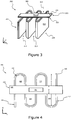
- the figure 5 now shows a longitudinal section of the support 210, in a plane defined by the directions Y and Z.
- the support comprises a first plate 230 and a second plate 240, joined together at their first large face, respectively 231 and 241.
- the first plate comprises at its first large face 231 a groove 232 covered by the first large face 241 of the second plate, so as to form a single channel 250.
- the figure 6 presents a flattened view of the first plate 230 to facilitate the reader's understanding of the arrangement of the groove 232 on the first large surface 231.
- the groove 232 extends between two opposite lateral edges delimiting the first large face 231. More specifically, the groove extends between a first lateral edge 233 in contact with the plate 220 and a second opposite lateral edge 234.
- the groove comprises first portions 235 parallel or substantially parallel to the first side edge 233 connected by second portions 236.
- the groove 232 thus has a serpentine configuration.
- the total length of the first portions is greater than the total length of the second portions.
- the second portions form bends but they could also have a straight portion normal to the first portions.
- the present application proposes a cooling device comprising a pulsed heat pipe, less expensive to produce, more economical to use and more efficient, for the same given volume, compared to the state of the art.
- the height "H” may for example be between 10mm and 1000mm, preferably between 100mm and 500mm, when the heat source has a power between 10W and 300W.
- the total length of the support 210 is chosen so that the surface of its first large face 211 and of its second large face 212 is between 90mm and 4000mm, it is preferably equal to or less than 1350mm, when the heat source has a power between 10W and 300W.
- the values mentioned above depend on external parameters such as, for example, the power of the heat source and the ambient temperature, but also parameters intrinsic to the device, for example its thermal conductivity coefficient. Therefore, the invention is not limited to the ranges of values mentioned above.
- the distance "B” depends on the ambient temperature and the power of the heat source to be cooled.
- the distance “B” may for example be between 1 mm and 300 mm, preferably between 5mm and 100mm, when the heat source has a power between 10W and 300W.
- the thermal conduction plate 220 partially covers each duct 213 to allow evacuation of the air present in the ducts 213.
- Each duct has a length "C" in the lateral direction X greater than the length "C" of the plate 220.
- the ratio between the lengths "C” and “C” may be greater than 0.02, preferably between 0.03 and 0.5.
- the plate can cover less than 50% of the surface of each conduit 213, preferably covering between 10% and 40% of their surface.
- the thermal conduction plate 220 transmits the heat produced by the heat source 300 to the support 210.
- the latter comprises a channel 250 delimited by the first plate 230 and the second 240. More precisely, the channel 250 with a rectangular section as illustrated in FIG. figure 5 however, the section of the channel may have other shapes, although less favorable to a flow of a liquid in the channel, of circular, oval or triangular type.
- the hydraulic diameter of the channel 250 is chosen so that the capillary forces acting on a fluid present in said channel, dominate with respect to the gravitational forces.
- the hydraulic diameter of the channel is chosen so that the channel 250 is characterized by a number of Eotvos at most equal to 4.
- the hydraulic diameter of the channel 250 may be less than 3 mm, preferably included between 500 ⁇ m and 2mm.
- the channel 250 comprises first portions 235 parallel or substantially parallel to the first lateral edge 233 of the first plate 230.
- the distance between two adjacent first portions is chosen so as to promote a homogeneous diffusion of the heat produced by the heat source 300 at the large faces 211 and 212 of the support.
- the distance between two first portions is chosen so as to minimize the non-isothermality or, in other words, to guarantee a uniform temperature between the first portions. More precisely, the value of this distance is chosen so that the temperature gradient between two first adjacent portions 235 does not exceed 5K.
- the value of this distance "T" is according to the present example, between 10mm and 150mm, preferably between 50mm and 120mm.
- the total length of the channel 250 is chosen so as to sufficiently dissipate the heat produced by the heat source 300 at the support 210.
- this total length depends on external parameters, such as for example the power of the heat source. and the ambient temperature, but also parameters intrinsic to the device such as its surface, the number of ducts formed and its coefficient of thermal conductivity.
- the total length of the channel 250 may be between 180mm and 4000mm, it is preferably equal to or less than 300mm.
- the channel 250 contains a heat transfer fluid 251 to change state to form an oscillating heat pipe 252, also known by the name of "heat pipe” or under the acronym “PHP” for "pulsating heat pipe” in English terminology.
- the channel 250 is partially filled with heat transfer fluid which naturally takes the form of a succession of vapor bubbles and liquid plugs when heated.
- the heat transfer fluid 251 is according to the present example of acetone, filling 50% of the volume of the channel at room temperature, that is to say at a temperature of about 20 ° C.
- This phase separation results mainly from surface tension forces.
- the oscillating heat pipe 252 is heated in a hot part and cooled in a cold part, the resulting temperature differences generate both temporal and spatial pressure fluctuations, which are themselves associated with the generation and growth of vapor bubbles. in the evaporator and their implosion in the condenser. These fluctuations act as a pumping system to transport liquid and vapor bubbles between hot and cold parts.
- the hot parts of the oscillating heat pipe are located opposite the plate 220.
- the plates 230 and 240 are made from the same material.
- the thickness of the plates is as thin as possible to minimize the amount of material used and allow easier folding of the support 210 after the two plates are joined together.
- the thickness of the first plate is sufficient to allow the machining of the channel 250 in the first large face 231 of the first plate 230.
- a second channel may be formed in a first large face 241 of the second plate 240 so that said channels are superimposed and form a single channel 250.
- the plates used to form the support 210 have a high coefficient of thermal conductivity, preferably greater than 150 W.m -1 .K -1 in order to quickly dissipate the heat produced by the heat source 300 in the support 210.
- a support characterized by a high coefficient of thermal conductivity makes it possible to space the first portions of the channel 250 more widely. As a result, the total length of the channel can be reduced, which saves time and cost. during its production, this also makes it possible to use less heat transfer fluid 251.
- the plate is advantageously metallic: it may preferably consist of aluminum or an alloy of aluminum or copper.
- a cooling device is characterized by several parameters described above which depend on the ambient temperature as well as the thermal power dissipated by the heat source 300.
- Table 1 shown in FIG. figure 7 illustrates several embodiments of the invention from a device as described above. More specifically, each of the examples mentioned in Table 1 comprises an aluminum thermal conduction plate 210, whose thickness is 3 mm. Of course, the plate is centered in the middle of the ducts as shown in FIG. figure 4 .
- the cooling devices described in Table 1 are also characterized by a channel 250 of square section of 1.5 mm side, filled with an ethanol-type heat transfer fluid. The first and second platinum each have a thickness equal to 1.5mm.
- the other technical characteristics of each embodiment are mentioned in Table 1. Of course, other embodiments can be envisaged as a function of other heat source powers and other ambient temperature ranges, so that the This application is not limited to these examples.
- the support 210 may advantageously be manufactured by a three-dimensional printing technique, preferably from one of the materials mentioned above.
- This method of manufacture offers the advantage of being able to produce elaborate shapes of coils without it being necessary for this purpose to mechanically bend the support 210.
- This method of manufacture thus makes it possible to produce more complex serpentine shapes while limiting the risk of damage to the support 210 during its shaping.
- the materials generally used for three-dimensional printing are materials based on synthetic or artificial polymers, characterized by a low coefficient of thermal conductivity thereby limiting the diffusion of heat at the large faces of the support 210
- the figure 8 shows an embodiment of a cooling device 400 according to the invention. It should be noted that the numbers comprising the same tens designate elements whose functions are identical or similar to the device 200 described above.
- the figure 8 shows a longitudinal section of the support 410, in a plane defined by the directions Y and Z.
- the cooling device 400 is similar to the cooling device 200 described above, except that the support 410 comprises a second groove 437 on the second major face 438 of the first turntable 430.
- the second groove 437 is closed by a third turntable 460 joined to the first turntable 430.
- the support 400 comprises a second channel 451 present between the first turntable 430 and the Third platen 460.
- the second channel advantageously allows the heat produced by the heat source 300 to heat homogeneously the support 410 when its coefficient of thermal conductivity is low.
- the shape of the second channel 451 is preferably identical to that of the first channel 450. However, their shape and their arrangement may be different or complementary.
- the plates covering the grooves present on each side of the first plate 430 are of thickness thinner than the thickness of the first plate in order to promote the diffusion of heat on the surface of the support 410.
- the second and the third stage can be made from materials whose thermal diffusion coefficient is greater than that of the first platinum.
- the first platen 430 may be made from polymers and the second and third platinum metal based such as aluminum.
- a thermal interface material may be interposed between one or more elements composing a cooling device described above.
- the thermal interface material may be interposed between the two plates 230 and 240 and / or between the plate 220 and the support 210.
- a heat source 300 mentioned above may designate at least one of the following elements: a lighting device comprising power LEDs, a photovoltaic device, an electronic circuit, a thyristor type electronic power component or a insulated gate bipolar transistor, a battery, a fuel cell or any other power system.
Landscapes
- Engineering & Computer Science (AREA)
- General Engineering & Computer Science (AREA)
- Life Sciences & Earth Sciences (AREA)
- Sustainable Development (AREA)
- Physics & Mathematics (AREA)
- Thermal Sciences (AREA)
- Mechanical Engineering (AREA)
- Cooling Or The Like Of Electrical Apparatus (AREA)
Applications Claiming Priority (1)
| Application Number | Priority Date | Filing Date | Title |
|---|---|---|---|
| FR1654384A FR3051548B1 (fr) | 2016-05-17 | 2016-05-17 | Dispositif de refroidissement a caloduc pulse |
Publications (2)
| Publication Number | Publication Date |
|---|---|
| EP3246648A1 EP3246648A1 (fr) | 2017-11-22 |
| EP3246648B1 true EP3246648B1 (fr) | 2019-08-28 |
Family
ID=57348758
Family Applications (1)
| Application Number | Title | Priority Date | Filing Date |
|---|---|---|---|
| EP17305564.1A Active EP3246648B1 (fr) | 2016-05-17 | 2017-05-16 | Dispositif de refroidissement à caloduc pulsé |
Country Status (4)
| Country | Link |
|---|---|
| EP (1) | EP3246648B1 (es) |
| ES (1) | ES2755905T3 (es) |
| FR (1) | FR3051548B1 (es) |
| PT (1) | PT3246648T (es) |
Family Cites Families (3)
| Publication number | Priority date | Publication date | Assignee | Title |
|---|---|---|---|---|
| JPH0914875A (ja) * | 1995-06-29 | 1997-01-17 | Akutoronikusu Kk | 多孔扁平金属管ヒートパイプ式熱交換器 |
| CN100572908C (zh) * | 2006-11-17 | 2009-12-23 | 富准精密工业(深圳)有限公司 | 发光二极管灯具 |
| FR3007122B1 (fr) * | 2013-06-18 | 2017-09-08 | Commissariat Energie Atomique | Refroidissement de composants electroniques et/ou electriques par caloduc pulse et element de conduction thermique |
-
2016
- 2016-05-17 FR FR1654384A patent/FR3051548B1/fr not_active Expired - Fee Related
-
2017
- 2017-05-16 EP EP17305564.1A patent/EP3246648B1/fr active Active
- 2017-05-16 PT PT173055641T patent/PT3246648T/pt unknown
- 2017-05-16 ES ES17305564T patent/ES2755905T3/es active Active
Non-Patent Citations (1)
| Title |
|---|
| None * |
Also Published As
| Publication number | Publication date |
|---|---|
| EP3246648A1 (fr) | 2017-11-22 |
| FR3051548B1 (fr) | 2018-05-25 |
| PT3246648T (pt) | 2019-11-22 |
| FR3051548A1 (fr) | 2017-11-24 |
| ES2755905T3 (es) | 2020-04-24 |
Similar Documents
| Publication | Publication Date | Title |
|---|---|---|
| EP2770809B1 (fr) | Carte électronique | |
| EP3011249B1 (fr) | Refroidissement de composants électroniques et/ou électriques par caloduc pulsé et élément de conduction thermique | |
| EP2223583B1 (fr) | Dispositif de refroidissement d'une carte electronique par conduction a l'aide de caloducs, et procede de fabrication correspondant. | |
| EP2081422B1 (fr) | Boîtier en profilés extrudés métalliques multi-positions pour la fabrication d'un dispositif électronique de puissance étanche | |
| EP2795226B1 (fr) | Dispositif de refroidissement | |
| FR3024770A1 (fr) | Plaque d'echange thermique pour gestion thermique de pack batteries | |
| FR3076085A1 (fr) | Couvercle d’element electrochimique a conduction thermique renforcee | |
| FR3056290A1 (fr) | Dispositif de regulation thermique | |
| FR3016479A1 (fr) | Plaque d'echange thermique pour gestion thermique de batterie et procede de fabrication associe | |
| EP3008772B1 (fr) | Bloc batterie pour véhicule automobile | |
| EP3246648B1 (fr) | Dispositif de refroidissement à caloduc pulsé | |
| WO2018060604A1 (fr) | Dispositif de regulation thermique | |
| WO2018020139A1 (fr) | Echangeur de chaleur, notamment pour la regulation thermique d'une unite de reserve d'energie, et ensemble forme dudit echangeur et de ladite unite | |
| FR2989841A1 (fr) | Dispositif de regulation thermique pour module de batteries. | |
| FR3062522A1 (fr) | Batterie refroidie et systeme comportant une telle batterie | |
| EP2591513B1 (fr) | Dispositif de génération de courant et/ou de tension à base de module thermoélectrique disposé dans un flux de fluide | |
| FR3056829A1 (fr) | Dispositif de regulation thermique de batterie | |
| FR3056828A1 (fr) | Dispositif de regulation thermique | |
| EP3394552B1 (fr) | Dispositif de mise en temperature d'un objet | |
| FR3073612B1 (fr) | Tube pour echangeur de chaleur avec dispositif de perturbation | |
| EP3341977B1 (fr) | Convertisseur thermoelectrique thermiquement transparent | |
| FR3079354A1 (fr) | Systeme de regulation thermique d’au moins un module de stockage d’energie electrique | |
| FR3113336A1 (fr) | Dispositif de refroidissement de deux cellules électrochimiques, ensemble électrochimique et procédé correspondants | |
| FR3073611B1 (fr) | Tube pour echangeur de chaleur avec dispositif de perturbation de geometrie variable | |
| FR3056715B1 (fr) | Module thermoelectrique et dispositif comprenant un tel module |
Legal Events
| Date | Code | Title | Description |
|---|---|---|---|
| PUAI | Public reference made under article 153(3) epc to a published international application that has entered the european phase |
Free format text: ORIGINAL CODE: 0009012 |
|
| STAA | Information on the status of an ep patent application or granted ep patent |
Free format text: STATUS: THE APPLICATION HAS BEEN PUBLISHED |
|
| AK | Designated contracting states |
Kind code of ref document: A1 Designated state(s): AL AT BE BG CH CY CZ DE DK EE ES FI FR GB GR HR HU IE IS IT LI LT LU LV MC MK MT NL NO PL PT RO RS SE SI SK SM TR |
|
| AX | Request for extension of the european patent |
Extension state: BA ME |
|
| STAA | Information on the status of an ep patent application or granted ep patent |
Free format text: STATUS: REQUEST FOR EXAMINATION WAS MADE |
|
| 17P | Request for examination filed |
Effective date: 20180314 |
|
| RAV | Requested validation state of the european patent: fee paid |
Extension state: MA Effective date: 20180314 |
|
| RBV | Designated contracting states (corrected) |
Designated state(s): AL AT BE BG CH CY CZ DE DK EE ES FI FR GB GR HR HU IE IS IT LI LT LU LV MC MK MT NL NO PL PT RO RS SE SI SK SM TR |
|
| RIC1 | Information provided on ipc code assigned before grant |
Ipc: F28D 15/02 20060101AFI20180712BHEP Ipc: F21V 29/00 20150101ALI20180712BHEP |
|
| GRAP | Despatch of communication of intention to grant a patent |
Free format text: ORIGINAL CODE: EPIDOSNIGR1 |
|
| STAA | Information on the status of an ep patent application or granted ep patent |
Free format text: STATUS: GRANT OF PATENT IS INTENDED |
|
| INTG | Intention to grant announced |
Effective date: 20180817 |
|
| GRAS | Grant fee paid |
Free format text: ORIGINAL CODE: EPIDOSNIGR3 |
|
| RAP1 | Party data changed (applicant data changed or rights of an application transferred) |
Owner name: EUROPHANE SAS |
|
| GRAA | (expected) grant |
Free format text: ORIGINAL CODE: 0009210 |
|
| STAA | Information on the status of an ep patent application or granted ep patent |
Free format text: STATUS: THE PATENT HAS BEEN GRANTED |
|
| AK | Designated contracting states |
Kind code of ref document: B1 Designated state(s): AL AT BE BG CH CY CZ DE DK EE ES FI FR GB GR HR HU IE IS IT LI LT LU LV MC MK MT NL NO PL PT RO RS SE SI SK SM TR |
|
| REG | Reference to a national code |
Ref country code: GB Ref legal event code: FG4D Free format text: NOT ENGLISH |
|
| REG | Reference to a national code |
Ref country code: CH Ref legal event code: EP |
|
| REG | Reference to a national code |
Ref country code: AT Ref legal event code: REF Ref document number: 1172932 Country of ref document: AT Kind code of ref document: T Effective date: 20190915 |
|
| REG | Reference to a national code |
Ref country code: IE Ref legal event code: FG4D Free format text: LANGUAGE OF EP DOCUMENT: FRENCH |
|
| REG | Reference to a national code |
Ref country code: DE Ref legal event code: R096 Ref document number: 602017006568 Country of ref document: DE |
|
| REG | Reference to a national code |
Ref country code: CH Ref legal event code: NV Representative=s name: ABREMA AGENCE BREVETS ET MARQUES, GANGUILLET, CH |
|
| REG | Reference to a national code |
Ref country code: PT Ref legal event code: SC4A Ref document number: 3246648 Country of ref document: PT Date of ref document: 20191122 Kind code of ref document: T Free format text: AVAILABILITY OF NATIONAL TRANSLATION Effective date: 20191113 |
|
| REG | Reference to a national code |
Ref country code: NL Ref legal event code: MP Effective date: 20190828 |
|
| REG | Reference to a national code |
Ref country code: LT Ref legal event code: MG4D |
|
| PG25 | Lapsed in a contracting state [announced via postgrant information from national office to epo] |
Ref country code: FI Free format text: LAPSE BECAUSE OF FAILURE TO SUBMIT A TRANSLATION OF THE DESCRIPTION OR TO PAY THE FEE WITHIN THE PRESCRIBED TIME-LIMIT Effective date: 20190828 Ref country code: HR Free format text: LAPSE BECAUSE OF FAILURE TO SUBMIT A TRANSLATION OF THE DESCRIPTION OR TO PAY THE FEE WITHIN THE PRESCRIBED TIME-LIMIT Effective date: 20190828 Ref country code: SE Free format text: LAPSE BECAUSE OF FAILURE TO SUBMIT A TRANSLATION OF THE DESCRIPTION OR TO PAY THE FEE WITHIN THE PRESCRIBED TIME-LIMIT Effective date: 20190828 Ref country code: NO Free format text: LAPSE BECAUSE OF FAILURE TO SUBMIT A TRANSLATION OF THE DESCRIPTION OR TO PAY THE FEE WITHIN THE PRESCRIBED TIME-LIMIT Effective date: 20191128 Ref country code: BG Free format text: LAPSE BECAUSE OF FAILURE TO SUBMIT A TRANSLATION OF THE DESCRIPTION OR TO PAY THE FEE WITHIN THE PRESCRIBED TIME-LIMIT Effective date: 20191128 Ref country code: LT Free format text: LAPSE BECAUSE OF FAILURE TO SUBMIT A TRANSLATION OF THE DESCRIPTION OR TO PAY THE FEE WITHIN THE PRESCRIBED TIME-LIMIT Effective date: 20190828 Ref country code: NL Free format text: LAPSE BECAUSE OF FAILURE TO SUBMIT A TRANSLATION OF THE DESCRIPTION OR TO PAY THE FEE WITHIN THE PRESCRIBED TIME-LIMIT Effective date: 20190828 |
|
| PG25 | Lapsed in a contracting state [announced via postgrant information from national office to epo] |
Ref country code: GR Free format text: LAPSE BECAUSE OF FAILURE TO SUBMIT A TRANSLATION OF THE DESCRIPTION OR TO PAY THE FEE WITHIN THE PRESCRIBED TIME-LIMIT Effective date: 20191129 Ref country code: LV Free format text: LAPSE BECAUSE OF FAILURE TO SUBMIT A TRANSLATION OF THE DESCRIPTION OR TO PAY THE FEE WITHIN THE PRESCRIBED TIME-LIMIT Effective date: 20190828 Ref country code: AL Free format text: LAPSE BECAUSE OF FAILURE TO SUBMIT A TRANSLATION OF THE DESCRIPTION OR TO PAY THE FEE WITHIN THE PRESCRIBED TIME-LIMIT Effective date: 20190828 Ref country code: IS Free format text: LAPSE BECAUSE OF FAILURE TO SUBMIT A TRANSLATION OF THE DESCRIPTION OR TO PAY THE FEE WITHIN THE PRESCRIBED TIME-LIMIT Effective date: 20191228 Ref country code: RS Free format text: LAPSE BECAUSE OF FAILURE TO SUBMIT A TRANSLATION OF THE DESCRIPTION OR TO PAY THE FEE WITHIN THE PRESCRIBED TIME-LIMIT Effective date: 20190828 |
|
| REG | Reference to a national code |
Ref country code: AT Ref legal event code: MK05 Ref document number: 1172932 Country of ref document: AT Kind code of ref document: T Effective date: 20190828 |
|
| PG25 | Lapsed in a contracting state [announced via postgrant information from national office to epo] |
Ref country code: TR Free format text: LAPSE BECAUSE OF FAILURE TO SUBMIT A TRANSLATION OF THE DESCRIPTION OR TO PAY THE FEE WITHIN THE PRESCRIBED TIME-LIMIT Effective date: 20190828 |
|
| REG | Reference to a national code |
Ref country code: ES Ref legal event code: FG2A Ref document number: 2755905 Country of ref document: ES Kind code of ref document: T3 Effective date: 20200424 |
|
| PG25 | Lapsed in a contracting state [announced via postgrant information from national office to epo] |
Ref country code: PL Free format text: LAPSE BECAUSE OF FAILURE TO SUBMIT A TRANSLATION OF THE DESCRIPTION OR TO PAY THE FEE WITHIN THE PRESCRIBED TIME-LIMIT Effective date: 20190828 Ref country code: EE Free format text: LAPSE BECAUSE OF FAILURE TO SUBMIT A TRANSLATION OF THE DESCRIPTION OR TO PAY THE FEE WITHIN THE PRESCRIBED TIME-LIMIT Effective date: 20190828 Ref country code: RO Free format text: LAPSE BECAUSE OF FAILURE TO SUBMIT A TRANSLATION OF THE DESCRIPTION OR TO PAY THE FEE WITHIN THE PRESCRIBED TIME-LIMIT Effective date: 20190828 Ref country code: AT Free format text: LAPSE BECAUSE OF FAILURE TO SUBMIT A TRANSLATION OF THE DESCRIPTION OR TO PAY THE FEE WITHIN THE PRESCRIBED TIME-LIMIT Effective date: 20190828 Ref country code: IT Free format text: LAPSE BECAUSE OF FAILURE TO SUBMIT A TRANSLATION OF THE DESCRIPTION OR TO PAY THE FEE WITHIN THE PRESCRIBED TIME-LIMIT Effective date: 20190828 Ref country code: DK Free format text: LAPSE BECAUSE OF FAILURE TO SUBMIT A TRANSLATION OF THE DESCRIPTION OR TO PAY THE FEE WITHIN THE PRESCRIBED TIME-LIMIT Effective date: 20190828 |
|
| PG25 | Lapsed in a contracting state [announced via postgrant information from national office to epo] |
Ref country code: SK Free format text: LAPSE BECAUSE OF FAILURE TO SUBMIT A TRANSLATION OF THE DESCRIPTION OR TO PAY THE FEE WITHIN THE PRESCRIBED TIME-LIMIT Effective date: 20190828 Ref country code: CZ Free format text: LAPSE BECAUSE OF FAILURE TO SUBMIT A TRANSLATION OF THE DESCRIPTION OR TO PAY THE FEE WITHIN THE PRESCRIBED TIME-LIMIT Effective date: 20190828 Ref country code: SM Free format text: LAPSE BECAUSE OF FAILURE TO SUBMIT A TRANSLATION OF THE DESCRIPTION OR TO PAY THE FEE WITHIN THE PRESCRIBED TIME-LIMIT Effective date: 20190828 Ref country code: IS Free format text: LAPSE BECAUSE OF FAILURE TO SUBMIT A TRANSLATION OF THE DESCRIPTION OR TO PAY THE FEE WITHIN THE PRESCRIBED TIME-LIMIT Effective date: 20200224 |
|
| REG | Reference to a national code |
Ref country code: DE Ref legal event code: R097 Ref document number: 602017006568 Country of ref document: DE |
|
| PLBE | No opposition filed within time limit |
Free format text: ORIGINAL CODE: 0009261 |
|
| STAA | Information on the status of an ep patent application or granted ep patent |
Free format text: STATUS: NO OPPOSITION FILED WITHIN TIME LIMIT |
|
| PG2D | Information on lapse in contracting state deleted |
Ref country code: IS |
|
| 26N | No opposition filed |
Effective date: 20200603 |
|
| PG25 | Lapsed in a contracting state [announced via postgrant information from national office to epo] |
Ref country code: SI Free format text: LAPSE BECAUSE OF FAILURE TO SUBMIT A TRANSLATION OF THE DESCRIPTION OR TO PAY THE FEE WITHIN THE PRESCRIBED TIME-LIMIT Effective date: 20190828 |
|
| REG | Reference to a national code |
Ref country code: CH Ref legal event code: PFUS Owner name: EUROPHANE SAS, FR Free format text: FORMER OWNER: EUROPHANE SAS, FR |
|
| REG | Reference to a national code |
Ref country code: DE Ref legal event code: R119 Ref document number: 602017006568 Country of ref document: DE |
|
| PG25 | Lapsed in a contracting state [announced via postgrant information from national office to epo] |
Ref country code: MC Free format text: LAPSE BECAUSE OF FAILURE TO SUBMIT A TRANSLATION OF THE DESCRIPTION OR TO PAY THE FEE WITHIN THE PRESCRIBED TIME-LIMIT Effective date: 20190828 Ref country code: LI Free format text: LAPSE BECAUSE OF NON-PAYMENT OF DUE FEES Effective date: 20200531 Ref country code: CH Free format text: LAPSE BECAUSE OF NON-PAYMENT OF DUE FEES Effective date: 20200531 |
|
| REG | Reference to a national code |
Ref country code: BE Ref legal event code: MM Effective date: 20200531 |
|
| PG25 | Lapsed in a contracting state [announced via postgrant information from national office to epo] |
Ref country code: LU Free format text: LAPSE BECAUSE OF NON-PAYMENT OF DUE FEES Effective date: 20200516 |
|
| PG25 | Lapsed in a contracting state [announced via postgrant information from national office to epo] |
Ref country code: FR Free format text: LAPSE BECAUSE OF NON-PAYMENT OF DUE FEES Effective date: 20200531 Ref country code: IE Free format text: LAPSE BECAUSE OF NON-PAYMENT OF DUE FEES Effective date: 20200516 Ref country code: PT Free format text: LAPSE BECAUSE OF NON-PAYMENT OF DUE FEES Effective date: 20210315 |
|
| PG25 | Lapsed in a contracting state [announced via postgrant information from national office to epo] |
Ref country code: BE Free format text: LAPSE BECAUSE OF NON-PAYMENT OF DUE FEES Effective date: 20200531 Ref country code: DE Free format text: LAPSE BECAUSE OF NON-PAYMENT OF DUE FEES Effective date: 20201201 |
|
| VS25 | Lapsed in a validation state [announced via postgrant information from nat. office to epo] |
Ref country code: MA Free format text: LAPSE BECAUSE OF FAILURE TO SUBMIT A TRANSLATION OF THE DESCRIPTION OR TO PAY THE FEE WITHIN THE PRESCRIBED TIME-LIMIT Effective date: 20190828 |
|
| PG25 | Lapsed in a contracting state [announced via postgrant information from national office to epo] |
Ref country code: ES Free format text: LAPSE BECAUSE OF NON-PAYMENT OF DUE FEES Effective date: 20200517 |
|
| GBPC | Gb: european patent ceased through non-payment of renewal fee |
Effective date: 20210516 |
|
| PG25 | Lapsed in a contracting state [announced via postgrant information from national office to epo] |
Ref country code: GB Free format text: LAPSE BECAUSE OF NON-PAYMENT OF DUE FEES Effective date: 20210516 |
|
| PG25 | Lapsed in a contracting state [announced via postgrant information from national office to epo] |
Ref country code: MT Free format text: LAPSE BECAUSE OF FAILURE TO SUBMIT A TRANSLATION OF THE DESCRIPTION OR TO PAY THE FEE WITHIN THE PRESCRIBED TIME-LIMIT Effective date: 20190828 Ref country code: CY Free format text: LAPSE BECAUSE OF FAILURE TO SUBMIT A TRANSLATION OF THE DESCRIPTION OR TO PAY THE FEE WITHIN THE PRESCRIBED TIME-LIMIT Effective date: 20190828 |
|
| PG25 | Lapsed in a contracting state [announced via postgrant information from national office to epo] |
Ref country code: MK Free format text: LAPSE BECAUSE OF FAILURE TO SUBMIT A TRANSLATION OF THE DESCRIPTION OR TO PAY THE FEE WITHIN THE PRESCRIBED TIME-LIMIT Effective date: 20190828 |