EP3246581A1 - Halter zum befestigen einer sanitärkomponente an einer wand - Google Patents
Halter zum befestigen einer sanitärkomponente an einer wand Download PDFInfo
- Publication number
- EP3246581A1 EP3246581A1 EP17171294.6A EP17171294A EP3246581A1 EP 3246581 A1 EP3246581 A1 EP 3246581A1 EP 17171294 A EP17171294 A EP 17171294A EP 3246581 A1 EP3246581 A1 EP 3246581A1
- Authority
- EP
- European Patent Office
- Prior art keywords
- holder
- adhesive component
- chamber
- adhesive
- wall
- Prior art date
- Legal status (The legal status is an assumption and is not a legal conclusion. Google has not performed a legal analysis and makes no representation as to the accuracy of the status listed.)
- Granted
Links
Images

Classifications
-
- F—MECHANICAL ENGINEERING; LIGHTING; HEATING; WEAPONS; BLASTING
- F16—ENGINEERING ELEMENTS AND UNITS; GENERAL MEASURES FOR PRODUCING AND MAINTAINING EFFECTIVE FUNCTIONING OF MACHINES OR INSTALLATIONS; THERMAL INSULATION IN GENERAL
- F16B—DEVICES FOR FASTENING OR SECURING CONSTRUCTIONAL ELEMENTS OR MACHINE PARTS TOGETHER, e.g. NAILS, BOLTS, CIRCLIPS, CLAMPS, CLIPS OR WEDGES; JOINTS OR JOINTING
- F16B11/00—Connecting constructional elements or machine parts by sticking or pressing them together, e.g. cold pressure welding
- F16B11/006—Connecting constructional elements or machine parts by sticking or pressing them together, e.g. cold pressure welding by gluing
-
- F—MECHANICAL ENGINEERING; LIGHTING; HEATING; WEAPONS; BLASTING
- F16—ENGINEERING ELEMENTS AND UNITS; GENERAL MEASURES FOR PRODUCING AND MAINTAINING EFFECTIVE FUNCTIONING OF MACHINES OR INSTALLATIONS; THERMAL INSULATION IN GENERAL
- F16B—DEVICES FOR FASTENING OR SECURING CONSTRUCTIONAL ELEMENTS OR MACHINE PARTS TOGETHER, e.g. NAILS, BOLTS, CIRCLIPS, CLAMPS, CLIPS OR WEDGES; JOINTS OR JOINTING
- F16B47/00—Suction cups for attaching purposes; Equivalent means using adhesives
- F16B47/003—Suction cups for attaching purposes; Equivalent means using adhesives using adhesives for attaching purposes
Definitions
- the present invention relates to a holder for fixing a sanitary component to a wall.
- accessories such as soap dispensers, paper holders, toilet brush sets, (clothing) hooks, etc., or shower bars can be fastened to walls of sanitary rooms with such holders.
- the object of the invention is therefore to solve the problems described with reference to the prior art at least partially and in particular to provide a holder for attaching a sanitary component to a wall that can be fastened easily and without damaging tiles on a wall of a sanitary room and at the same time a particularly durable bond allows.
- the holder for attaching a sanitary component to a wall has a housing with at least one chamber for at least one adhesive component, wherein the at least one adhesive component can be pressed out of the at least one chamber by means of a mechanical actuator, so that the at least one first adhesive component of at least one opening of the Housing outlet, wherein the at least one opening opens into at least one curing chamber for the at least one adhesive component and wherein the at least one curing chamber is limited by at least one grid, so when curing the at least one adhesive component in the at least one curing chamber ambient air through the at least one grid the at least one adhesive component passes.
- the proposed holder is used in particular to attach a sanitary component to a wall.
- a sanitary component may be, for example, accessories, such as soap dispensers, paper holders, toilet brush sets, (clothes) hooks, etc., and / or shower bars.
- the holder may be a separate component to which the sanitary component can be fastened. Furthermore, the holder can also be formed integrally with the sanitary component.
- the holder has an (outer) housing, which is in particular at least partially made of metal or plastic.
- the holder is designed in particular with a wall mounting device.
- the wall mounting device may comprise at least one bore for mounting the holder to the wall by means of screws, clips and the like.
- the wall mounting device may also be one to the sanitary component aligned, (in particular opposite or remote) contact surface towards the wall include, which is preferably flat.
- the housing in particular has an (internal) cavity in which at least partially (preferably completely) at least one chamber for at least one adhesive component, in particular a first chamber for a first adhesive component, a second chamber for a second adhesive component and / or a third Chamber for a third adhesive component, is arranged.
- the at least one adhesive component may in particular be a one-component adhesive with a single adhesive component, a two-component adhesive with a first adhesive component and second adhesive component or a three-component adhesive with a first adhesive component, second adhesive component and third adhesive component.
- a one-component adhesive it can in particular be an adhesive based on silane-modified polymers (MS polymer, hybrid polymer, STPU, etc.).
- Such hybrid adhesives require moisture or humidity for curing.
- the first adhesive component is resin and the second adhesive component is, for example, a hardener. By mixing the first adhesive component and the second adhesive component, a curing reaction is started.
- the at least one adhesive component (and preferably all the adhesive components) can be pressed out of the at least one chamber by means of (at least) one mechanical actuator, such that with a movement of the actuator at the same time all the adhesive components through the at least one opening of the housing (together) enter the at least one curing chamber.
- the mechanical actuator can be, for example, a key of the holder, wherein the at least one adhesive component can be pressed out of the at least one chamber by pressing the key.
- the at least one opening of the housing opens into the at least one curing chamber, in which the at least one adhesive component in particular forms an adhesive gap (adjacent to the housing), so that the at least one adhesive component at least partially fills the at least one curing chamber.
- the holder is particularly easy to attach to a wall by actuation of the mechanical actuator.
- the at least one curing chamber is delimited by at least one grid, so that upon curing of the at least one adhesive component in the at least one curing chamber, ambient air passes through the at least one grid to the at least one adhesive component.
- the at least one curing chamber is a region of the housing in which the at least one adhesive component hardens when the holder is adhesively bonded to a wall. The at least one curing chamber therefore immediately adjoins the wall after the mounting of the holder.
- the adhesive gap is thus preferably formed in the at least one curing chamber.
- the at least one curing chamber is delimited by at least one grid, so that upon curing of the at least one adhesive component in the at least one curing chamber, ambient air passes through the at least one grid to the at least one adhesive component.
- the ambient air contains moisture, which is particularly required in the curing of one-component adhesives.
- the at least one grid thus allows ventilation, so that the use of corresponding one-component adhesives is made possible.
- the at least one grid span is advantageous if the at least one grid spans at least 30% of a contact surface of the housing to the wall. It is preferred that the at least one grid spans at least 40%, particularly preferably at least 50% of a contact surface of the housing to the wall. This ensures that the at least one adhesive component when curing in the at least one curing chamber for a rapid curing sufficient moisture is available.
- the at least one grid serves as the adhesive surface for the at least one adhesive component.
- the at least one adhesive component carries the holder after hardening of the at least one adhesive component (also) via the at least one grid.
- the at least one adhesive component also at least partially enters the at least one grid, so that after curing of the at least one adhesive component creates a particularly strong connection with the holder.
- a contact surface of the housing with the wall has at least one adhesive for pre-fixing the holder to the wall.
- the adhesive may be, for example, an (annular) adhesive film which fixes the holder to the wall before the at least one adhesive component has cured.
- the holder has a fastening means for fastening at least one cartridge which at least partially forms the at least one chamber for the at least one adhesive component.
- the fastening means may be, for example, a thread with which the cartridge can be screwed to the housing.
- the fastening means has at least one mandrel.
- the mandrel is an element of the housing which (automatically) opens the closure of the at least one chamber, in particular when the cartridge is attached to the fastening means. In this way, a hand contact with the at least one adhesive component in the attachment of the holder can be effectively prevented.
- the at least one grid has a plurality of grid structures, between which at least one ventilation slot is formed, and wherein the at least one ventilation slot has a maximum width of 1 mm.
- the at least one ventilation slot preferably has a width of 0.3 mm (millimeters) to 0.7 mm.
- such a width of the at least one ventilation slit ensures that the at least one adhesive component distributes uniformly in the at least one curing chamber, without a substantial proportion of the at least one adhesive component running out of the at least one curing chamber through the at least one grid, and, on the other hand, that sufficient Ambient air reaches the at least one adhesive component during curing.
- the at least one ventilation slot tapers in the direction of the at least one curing chamber. This has the advantage that the at least one adhesive component can settle like a wedge in the at least one grid after it has cured, resulting in a particularly stable connection.
- the at least one grid delimits the at least one curing chamber at a depth of the at least one curing chamber of not more than 1 mm.
- the at least one grid limits the at least one curing chamber at a depth of the at least one curing chamber of 0.7 mm to 0.9 mm. In this way, a particularly high strength of the holder can be achieved on the wall.
- the housing has a first chamber for a first adhesive component and a second chamber for a second adhesive component, wherein the first adhesive component and the second adhesive component can be pressed out of the first chamber and the second chamber by means of the mechanical actuator, so that the first adhesive component and the second adhesive component emerge from the at least one opening of the housing.
- the at least one opening is arranged on a contact surface of the housing to the wall.
- the contact surface of the housing is in particular that side of the housing which is in contact with the wall after the attachment of the holder.
- the at least one chamber is a, in particular elastic, adhesive cartridge.
- the at least one chamber can be formed at least partially from a plastic film.
- the at least one adhesive component can thus be pressed out of the at least one chamber in a particularly simple manner by pressure of the mechanical actuator on the at least one chamber.
- the at least one chamber has at least one closure.
- the at least one closure is in particular designed such that it automatically opens by pressure of the mechanical actuator to the at least one chamber.
- the at least one closure can in particular have predetermined breaking points which yield at a certain pressure level in the at least one chamber.
- the mechanical actuator is at least partially adjustable into the housing. That means in other words z.
- the actuator extends both outside and inside the housing, and can be moved inside by means of an external actuation.
- the holder it is advantageous for the holder to have a mixing chamber in which the at least one adhesive component can be mixed before it leaves the at least one opening.
- mixing structures can be arranged which ensure as complete a mixing as possible of the at least one adhesive component.
- the holder has a channel, via which the at least one adhesive component after pressing out of the at least one chamber one of visible outside of the housing can be fed so that curing of the at least one adhesive component can be tested.
- the channel can guide the at least one adhesive component in the direction or to the mechanical actuator.
- the mechanical actuator may also be at least partially transparent, so that the at least one adhesive component is visible from the outside by the mechanical actuator.
- the at least one adhesive component can be designed such that it undergoes a color change during curing. This can be checked by a visual inspection, whether the adhesive has cured.
- the housing on a contact surface to the wall has a recess for forming a bonding gap between the housing and the wall.
- the at least one opening of the housing opens in particular in this recess, so that the at least one adhesive component at least partially fills the return after the bonding.
- the holder forms in particular opposite to the holding means (hook, clip, socket, etc.) the bond.
- step c it is also possible to apply a plurality of adhesive components, in particular simultaneously.
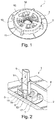
- the Fig. 1 shows a first embodiment of the holder 1 for attaching a sanitary component, not shown here on a wall 8 in a perspective view.
- a housing 2 of the holder 1 here has in a central region a chamber 3 with a fastening means 18, which is a thread.
- a cartridge 14 attachable on the fastening means 18, as in the following Fig. 2 shown.
- the housing 2 of the holder 1 also has a grid 16 with grid structures 11 and ventilation slots 10.
- the Fig. 2 shows the first embodiment of the holder 1 in a perspective sectional view.
- the housing 2 of the holder 1 rests with its docking surface 7 on the wall 8 and is pre-fixed to the wall 8 with an annular adhesive 17, which is an adhesive tape here.
- Attached to the attachment means 18 of the housing 2 is a cartridge 14 with a mechanical actuator 5.
- the cartridge 14 forms with the housing 2 the chamber 3 for a one-component adhesive.
- the one-component adhesive can be pressed out of the chamber 3 by means of the mechanical actuator 5 through an opening 6 in a curing chamber 15 between the wall 8 and the housing 2, wherein the curing chamber 15 is formed here as a recess 13.
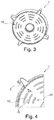
- the Fig. 3 shows a second embodiment of the holder 1 in a perspective view.
- the grid 16 can be seen here.
- the Fig. 4 shows the second embodiment of the holder 1 in a partial view.
- the grid 16 has a plurality of grid structures 11, between which ventilation slots 10 are formed.
- the ventilation slots 10 here have a width 4 of 0.5 mm.
- the Fig. 5 shows the fourth embodiment of the holder 1 in a sectional view. Again, the width 4 of the ventilation slots 10 between the grid structures 11 of the Grid 16 shown. Furthermore, the ventilation slots 10 taper in the direction of the curing chamber 15. The curing chamber 15 is limited by the grid structures 11 of the grid 16, starting from the contact surface 7 of the housing 2 at a depth 9 of 0.8 mm.
- the Fig. 6 shows a third embodiment of the holder 1 in a perspective partial view.
- the housing 2 has here in the region of the fastening means 18 three mandrels 12, with which a not shown here closure 10 of the cartridge 14 when inserted into the fastener 18 can be opened automatically.
- the third embodiment of the holder 1 corresponds to the second embodiment of the holder 1.
- the holder of the invention is characterized by an easy attachability without damaging tiles and a high-strength adhesive bond.
Landscapes
- Engineering & Computer Science (AREA)
- General Engineering & Computer Science (AREA)
- Mechanical Engineering (AREA)
- Supports Or Holders For Household Use (AREA)
- Standing Axle, Rod, Or Tube Structures Coupled By Welding, Adhesion, Or Deposition (AREA)
Abstract
Description
- Die vorliegende Erfindung betrifft einen Halter zum Befestigen einer Sanitärkomponente an einer Wand. Mit solchen Haltern können insbesondere Accessoires, wie zum Beispiel Seifenspender, Papierhalter, Toilettenbürstengarnituren, (Kleider-)Haken etc., oder Brausestangen an Wänden von Sanitärräumen befestigt werden.
- Bekannte Halter zum Befestigen von Sanitärkomponenten werden regelmäßig mit Schrauben an einer Wand befestigt. Problematisch ist häufig, dass Wände in Sanitärräumen mit Fliesen verkleidet sind, die durch die Verschraubung beschädigt werden können. Weiterhin ist die Befestigung von Haltern mit Klebestreifen oder Kleber bekannt, wodurch eine Beschädigung der Fliesen vermieden werden kann. Nachteilig hieran ist jedoch, dass die Verklebung häufig nicht die erforderliche Haltbarkeit erreicht und die Anwendung von Klebesystemen sehr aufwendig ist. Zur Gewährleistung einer hohen Klebekraft werden unter anderem Hybridkleber verwendet, die zur Aushärtung Feuchtigkeit bzw. Luftfeuchtigkeit benötigen. Es wurde daher bereits versucht in Haltern poröses Material einzusetzen, durch das Umgebungsluft an den Klebstoff gelangen kann. Dieses Material hat jedoch die Haftung des Klebstoffs an dem Halter reduziert, sodass die Verklebung hohen Qualitätsansprüchen häufig nicht genügen konnte.
- Aufgabe der Erfindung ist daher, die mit Bezug auf den Stand der Technik geschilderten Probleme zumindest teilweise zu lösen und insbesondere einen Halter zum Befestigen einer Sanitärkomponente an einer Wand anzugeben, der einfach und ohne Beschädigung von Fliesen an einer Wand eines Sanitärraums befestigbar ist und der gleichzeitig eine besonders haltbare Verklebung ermöglicht.
- Diese Aufgaben werden gelöst mit einem Halter gemäß den Merkmalen des unabhängigen Patentanspruchs. Weitere vorteilhafte Ausgestaltungen des Halters sind in den abhängig formulierten Patentansprüchen angegeben. Es ist darauf hinzuweisen, dass die in den abhängig formulierten Patentansprüchen einzeln aufgeführten Merkmale in beliebiger technologisch sinnvoller Weise miteinander kombiniert werden können und weitere Ausgestaltungen der Erfindung definieren. Darüber hinaus werden die in den Patentansprüchen angegeben Merkmale in der Beschreibung näher präzisiert und erläutert, wobei weitere bevorzugte Ausgestaltungen der Erfindung dargestellt werden.
- Der Halter zum Befestigen einer Sanitärkomponente an einer Wand weist ein Gehäuse mit zumindest einer Kammer für zumindest eine Klebstoffkomponente auf, wobei die zumindest eine Klebstoffkomponente mittels eines mechanischen Stellglieds aus der zumindest einen Kammer herauspressbar ist, sodass die zumindest eine erste Klebstoffkomponente aus zumindest einer Öffnung des Gehäuses austritt, wobei die zumindest eine Öffnung in zumindest eine Aushärtekammer für die zumindest eine Klebstoffkomponente mündet und wobei die zumindest eine Aushärtekammer durch zumindest ein Gitter begrenzt wird, sodass beim Aushärten der zumindest einen Klebstoffkomponente in der zumindest einen Aushärtekammer Umgebungsluft durch das zumindest eine Gitter an die zumindest eine Klebstoffkomponente gelangt.
- Der vorgeschlagene Halter dient insbesondere der Befestigung einer Sanitärkomponente an einer Wand. Bei einer solchen Sanitärkomponente kann es sich beispielsweise um Accessoires, wie zum Beispiel Seifenspender, Papierhalter, Toilettenbürstengarnituren, (Kleider-)Haken etc., und/oder Brausestangen handeln. Bei dem Halter kann es sich um ein separates Bauteil handeln, an dem die Sanitärkomponente befestigbar ist. Weiterhin kann der Halter aber auch einstückig mit der Sanitärkomponente ausgebildet sein. Der Halter weist ein (äußeres) Gehäuse auf, das insbesondere zumindest teilweise aus Metall oder Kunststoff besteht. Der Halter ist insbesondere mit einer Wandmontageeinrichtung ausgeführt. Die Wandmontageeinrichtung kann mindestens eine Bohrung für die Montage des Halters an die Wand mittels Schrauben, Clips und dergleichen umfassen. Die Wandmontageeinrichtung kann auch eine zu der Sanitärkomponente ausgerichtete, (insbesondere gegenüberliegende bzw. abgewandte) Anlagefläche hin zur Wand umfassen, die bevorzugt plan ist.
- Zudem weist das Gehäuse insbesondere einen (innen liegenden) Hohlraum auf, in dem zumindest teilweise (bevorzugt vollständig) zumindest eine Kammer für zumindest eine Klebstoffkomponente, insbesondere eine erste Kammer für eine erste Klebstoffkomponente, eine zweite Kammer für eine zweite Klebstoffkomponente und/oder eine dritte Kammer für eine dritte Klebstoffkomponente, angeordnet ist. Bei der zumindest einen Klebstoffkomponente kann es sich insbesondere um einen Einkomponentenklebstoff mit einer einzigen Klebstoffkomponente, einem Zweikomponentenklebstoff mit einer ersten Klebstoffkomponente und zweiten Klebstoffkomponente oder um einen Dreikomponentenklebstoff mit einer ersten Klebstoffkomponente, zweiten Klebstoffkomponente und dritten Klebstoffkomponente handeln.
- Im Falle eines Einkomponentenklebstoffs kann es sich insbesondere um einen Klebstoff auf Basis von silanmodifizierter Polymere (MS-Polymer, Hybrid-Polymer, STPU usw.) handeln. Solche Hybrid-Klebstoffe benötigen Feuchtigkeit bzw. Luftfeuchtigkeit zum Aushärten. Im Falle eines Zweikomponentenklebstoffs handelt es sich bei der ersten Klebstoffkomponente beispielsweise um Harz und bei der zweiten Klebstoffkomponente beispielsweise um einen Härter. Durch Vermischen der ersten Klebstoffkomponente und der zweiten Klebstoffkomponente wird eine Aushärtereaktion gestartet.
- Die zumindest eine Klebstoffkomponente (und bevorzugt alle Klebstoffkomponenten) ist mittels (mindestens) eines mechanischen Stellglieds aus der zumindest einen Kammer herauspressbar, insbesondere in der Art, dass mit einer Bewegung des Stellglieds gleichzeitig alle Klebstoffkomponenten durch die zumindest eine Öffnung des Gehäuses (miteinander) in die zumindest eine Aushärtekammer eintreten. Bei dem mechanischen Stellglied kann es sich beispielsweise um eine Taste des Halters handeln, wobei durch Drücken der Taste die zumindest eine Klebstoffkomponente aus der zumindest einen Kammer herauspressbar ist. Durch das Herauspressen der zumindest einen Klebstoffkomponente tritt die zumindest eine Klebstoffkomponente, insbesondere alle Klebstoffkomponenten gemeinsam und/oder miteinander gemischt, aus der zumindest einen Öffnung (ggf. einer Lochplatte) des Gehäuses aus. Die zumindest eine Öffnung des Gehäuses mündet in die zumindest eine Aushärtekammer, in der die zumindest eine Klebstoffkomponente insbesondere einen Klebespalt (angrenzend zum Gehäuse) ausbildet, sodass die zumindest eine Klebstoffkomponente die zumindest eine Aushärtekammer zumindest teilweise ausfüllt. Hierdurch ist der Halter durch Betätigung des mechanischen Stellglieds besonders einfach an einer Wand befestigbar.
- Die zumindest eine Aushärtekammer wird durch zumindest ein Gitter begrenzt, sodass beim Aushärten der zumindest einen Klebstoffkomponente in der zumindest einen Aushärtekammer Umgebungsluft durch das zumindest eine Gitter an die zumindest eine Klebstoffkomponente gelangt. Bei der zumindest einen Aushärtekammer handelt es sich um einen Bereich des Gehäuses, in dem die zumindest eine Klebstoffkomponente beim Ankleben des Halters an eine Wand aushärtet. Die zumindest eine Aushärtekammer grenzt daher nach der Montage des Halters unmittelbar an die Wand. In der zumindest einen Aushärtekammer wird somit vorzugsweise der Klebespalt ausgebildet. Die zumindest eine Aushärtekammer wird durch zumindest ein Gitter begrenzt, sodass beim Aushärten der zumindest einen Klebstoffkomponente in der zumindest einen Aushärtekammer Umgebungsluft durch das zumindest eine Gitter an die zumindest eine Klebstoffkomponente gelangt. Die Umgebungsluft enthält Feuchtigkeit, die insbesondere bei der Aushärtung von Einkomponentenklebstoffen erforderlich ist. Das zumindest eine Gitter ermöglicht somit eine Belüftung, sodass die Verwendung entsprechender Einkomponentenklebstoffe erst ermöglicht wird.
- Zudem ist es vorteilhaft, wenn das zumindest eine Gitter mindestens 30 % einer Anlagefläche des Gehäuses zu der Wand überspannt. Bevorzugt ist, dass das zumindest eine Gitter mindestens 40 %, besonders bevorzugt mindestens 50 % einer Anlagefläche des Gehäuses zu der Wand überspannt. Damit wird gewährleistet, dass der zumindest einen Klebstoffkomponente beim Aushärten in der zumindest einen Aushärtekammer für eine zügige Aushärtung genügen Feuchtigkeit zur Verfügung steht.
- Besonders vorteilhaft ist es, wenn das zumindest eine Gitter als Klebefläche für die zumindest eine Klebstoffkomponente dient. Dies bedeutet, dass die zumindest eine Klebstoffkomponente den Halter nach dem Aushärten der zumindest einen Klebstoffkomponente (auch) über das zumindest eine Gitter trägt. Hierbei kann die zumindest eine Klebstoffkomponente auch zumindest teilweise in das zumindest eine Gitter eintretet, sodass nach dem Aushärten der zumindest einen Klebstoffkomponente eine besonders feste Verbindung mit dem Halter entsteht.
- Vorzugsweise weist eine Anlagefläche des Gehäuses zu der Wand zumindest ein Klebemittel zur Vorfixierung des Halters an der Wand auf. Bei dem Klebemittel kann es sich beispielsweise um eine (ringförmige) Klebefolie handeln, die den Halter an der Wand fixiert, bevor die zumindest eine Klebstoffkomponente ausgehärtet ist.
- Darüber hinaus ist es vorteilhaft, wenn der Halter ein Befestigungsmittel zur Befestigung zumindest einer Kartusche aufweist, die zumindest teilweise die zumindest eine Kammer für die zumindest eine Klebstoffkomponente bildet. Bei dem Befestigungsmittel kann es sich beispielweise um ein Gewinde handeln, mit dem die Kartusche an das Gehäuse schraubbar ist.
- Vorzugsweise weist das Befestigungsmittel zumindest einen Dorn auf. Bei dem Dorn handelt es sich insbesondere um ein Element des Gehäuses, dass den Verschluss der zumindest einen Kammer insbesondere beim Anbringen der Kartusche an dem Befestigungsmittel (automatisch) öffnet. Hierdurch kann ein Handkontakt mit der zumindest einen Klebstoffkomponente bei der Befestigung des Halters wirksam verhindert werden.
- Des Weiteren ist es vorteilhaft, wenn das zumindest eine Gitter eine Mehrzahl von Gitterstrukturen aufweist, zwischen denen zumindest ein Lüftungsschlitz ausgebildet ist und wobei der zumindest eine Lüftungsschlitz eine Breite von maximal 1 mm aufweist. Der zumindest eine Lüftungsschlitz weist bevorzugt eine Breite von 0,3 mm (Millimeter) bis 0,7 mm auf. Eine solche Breite des zumindest einen Lüftungsschlitzes gewährleistet einerseits, dass sich die zumindest eine Klebstoffkomponente gleichmäßig in der zumindest einen Aushärtekammer verteilt, ohne dass ein wesentlicher Anteil der zumindest einen Klebstoffkomponente durch das zumindest eine Gitter aus der zumindest eine Aushärtekammer herausläuft, und andererseits, dass genügenden Umgebungsluft an die zumindest eine Klebstoffkomponente beim Aushärten gelangt.
- Weiterhin ist es vorteilhaft, wenn sich der zumindest eine Lüftungsschlitz in Richtung der zumindest einen Aushärtekammer verjüngt. Dies hat den Vorteil, dass sich die zumindest eine Klebstoffkomponente nach ihrer Aushärtung keilartig in dem zumindest einen Gitter festsetzen kann, wodurch eine besonders stabile Verbindung entsteht.
- Zudem ist es vorteilhaft, wenn das zumindest eine Gitter die zumindest eine Aushärtekammer in einer Tiefe der zumindest einen Aushärtekammer von maximal 1 mm begrenzt. Bevorzugt begrenzt das zumindest eine Gitter die zumindest eine Aushärtekammer in einer Tiefe der zumindest einen Aushärtekammer von 0,7 mm bis 0,9 mm. Hierdurch kann eine besonders hohe Festigkeit des Halters an der Wand erreicht werden.
- Ebenfalls vorteilhaft ist es, wenn das Gehäuse eine erste Kammer für eine erste Klebstoffkomponente und eine zweite Kammer für eine zweite Klebstoffkomponente aufweist, wobei die erste Klebstoffkomponente und die zweite Klebstoffkomponente mittels des mechanischen Stellglieds aus der ersten Kammer und der zweiten Kammer herauspressbar sind, sodass die erste Klebstoffkomponente und die zweite Klebstoffkomponente aus der zumindest einen Öffnung des Gehäuses austreten.
- Zudem ist es vorteilhaft, wenn die mindestens eine Öffnung an einer Anlagefläche des Gehäuses zu der Wand angeordnet ist. Die Anlagefläche des Gehäuses ist insbesondere diejenige Seite des Gehäuses, die nach der Befestigung des Halters mit in der Wand in Kontakt steht.
- Ebenso ist es vorteilhaft, wenn es sich bei der zumindest einen Kammer um eine, insbesondere elastische, Klebepatrone handelt. Die zumindest eine Kammer kann zumindest teilweise aus einer Kunststofffolie gebildet sein. Die zumindest eine Klebstoffkomponente ist somit durch Druck des mechanischen Stellglieds auf die zumindest eine Kammer besonders einfach aus der zumindest einen Kammer herauspressbar.
- Weiterhin ist es vorteilhaft, wenn die zumindest eine Kammer einen zumindest einen Verschluss aufweist. Der zumindest eine Verschluss ist insbesondere derart ausgebildet, dass dieser durch Druck des mechanischen Stellglieds auf die zumindest eine Kammer automatisch öffnet. Der zumindest eine Verschluss kann hierzu insbesondere Sollbruchstellen aufweisen, die ab einem bestimmten Druckniveau in der zumindest einen Kammer nachgeben.
- Darüber hinaus ist es vorteilhaft, wenn das mechanische Stellglied zumindest teilweise in das Gehäuse hinein verstellbar ist. Das heißt mit anderen Worten z. B. auch, dass das Stellglied sich sowohl außerhalb als auch innerhalb des Gehäuses erstreckt, und mittels einer äußern Betätigung innen verlagert werden kann.
- Zudem ist es vorteilhaft, wenn der Halter eine Mischkammer aufweist, in der die zumindest eine Klebstoffkomponente vor dem Austreten aus der mindestens einen Öffnung mischbar ist. In der Mischkammer können Mischstrukturen angeordnet sein, die eine möglichst vollständige Durchmischung der zumindest einen Klebstoffkomponente gewährleisten.
- Ebenfalls vorteilhaft ist es, wenn der Halter einen Kanal aufweist, über den die zumindest eine Klebstoffkomponente nach dem Herauspressen aus der zumindest einen Kammer einem von außen sichtbaren Bereich des Gehäuses zuführbar sind, sodass ein Aushärten der zumindest einen Klebstoffkomponente prüfbar ist. Hierdurch wird eine Kontrolle des Aushärtevorgangs der zumindest einen Klebstoffkomponente nach deren Durchmischung ermöglicht. Insbesondere kann der Kanal die zumindest eine Klebstoffkomponente in Richtung beziehungsweise zu dem mechanischen Stellglied führen. Das mechanische Stellglied kann zudem zumindest teilweise transparent ausgebildet sein, sodass die zumindest eine Klebstoffkomponente durch das mechanische Stellglied von außen sichtbar ist. Zur Vereinfachung der Prüfung des Aushärtevorgangs können die zumindest eine Klebstoffkomponente derart ausgestaltet sein, dass diese beim Aushärten einer Farbveränderung unterliegen. Hierdurch kann durch eine Sichtkontrolle geprüft werden, ob der Kleber ausgehärtet ist.
- Des Weiteren ist es vorteilhaft, wenn das Gehäuse an einer Anlagefläche zu der Wand einen Rücksprung zur Ausbildung eines Klebespalts zwischen dem Gehäuse und der Wand aufweist. Die zumindest eine Öffnung des Gehäuses mündet insbesondere in diesen Rücksprung, sodass die zumindest eine Klebstoffkomponente den Rücksprung nach der Verklebung zumindest teilweise ausfüllt.
- Mit dem hier angeführten Halter lässt sich insbesondere für Accessoires und/oder Brausestangen ein Montageverfahren mit folgenden Schritten realisieren:
- a) Anordnen mindestens eines hier vorgeschlagenen Halters an einer Wand,
- b) Betätigen des Stellgliedes,
- c) Gezieltes Applizieren der zumindest einen Klebstoffkomponente an der Wand, die an das Gehäuse angrenzt,
- d) Ausbilden einer Verklebung, bei der Umgebungsluft durch zumindest ein Gitter an die zumindest eine Klebstoffkomponente gelangt,
- e) Befestigen eines Accessoires und/oder einer Brausestange.
- Die im Zusammenhang mit der Ausbildung und Funktion des hier vorgeschlagenen Halters genannten Aspekte - auch nachfolgend zu den Figuren - können zur Charakterisierung des Montageverfahrens gleichermaßen herangezogen werden.
- Der Halter bildet insbesondere gegenüberliegend zu den Haltemitteln (Haken, Klammer, Fassung, etc.) die Verklebung aus.
- Mittels Schritt c) können auch - insbesondere gleichzeitig - mehrere Klebstoffkomponenten appliziert werden.
- Die Erfindung sowie das technische Umfeld werden nachfolgend anhand der Figuren näher erläutert. Es ist darauf hinzuweisen, dass die Figuren besonders bevorzugte Ausführungsvarianten der Erfindung zeigen, diese jedoch nicht darauf beschränkt ist. Dabei sind gleiche Bauteile in den Figuren mit denselben Bezugszeichen versehen. Es zeigen schematisch:
- Fig. 1:
- eine erste Ausführungsvariante des Halters in einer perspektivischen Darstellung;
- Fig. 2:
- die erste Ausführungsvariante des Halters in einer perspektivischen Schnittdarstellung;
- Fig. 3:
- eine zweite Ausführungsvariante des Halters in einer perspektivischen Darstellung;
- Fig. 4:
- die zweit Ausführungsvariante des Halters in einer Teilansicht;
- Fig. 5:
- die zweite Ausführungsvariante des Halters in einer Schnittdarstellung; und
- Fig. 6:
- eine dritte Ausführungsvariante des Halters in einer perspektivischen Teilansicht.
- Die
Fig. 1 zeigt eine erste Ausführungsvariante des Halters 1 zum Befestigen einer hier nicht gezeigten Sanitärkomponente an einer Wand 8 in einer perspektivischen Darstellung. Ein Gehäuse 2 des Halters 1 weist hier in einem zentralen Bereich eine Kammer 3 mit einem Befestigungsmittel 18 auf, bei dem es sich um ein Gewinde handelt. An dem Befestigungsmittel 18 ist, wie nachfolgend in derFig. 2 gezeigt, eine Kartusche 14 befestigbar. Das Gehäuse 2 des Halters 1 weist zudem ein Gitter 16 mit Gitterstrukturen 11 und Lüftungsschlitzen 10 auf. - Die
Fig. 2 zeigt die erste Ausführungsvariante des Halters 1 in einer perspektivischen Schnittdarstellung. Das Gehäuse 2 des Halters 1 liegt mit seiner Anklagefläche 7 an der Wand 8 an und ist mit einem ringförmigen Klebemittel 17, bei dem es sich hier um ein Klebeband handelt, an der Wand 8 vorfixiert. An dem Befestigungsmittel 18 des Gehäuses 2 ist eine Kartusche 14 mit einem mechanischen Stellglied 5 befestigt. Die Kartusche 14 bildet mit dem Gehäuse 2 die Kammer 3 für einen Einkomponentenklebstoff. Der Einkomponentenklebstoff kann mittels des mechanischen Stellglieds 5 aus der Kammer 3 durch eine Öffnung 6 in eine Aushärtekammer 15 zwischen der Wand 8 und dem Gehäuse 2 herausgepresst werden, wobei die Aushärtekammer 15 hier als Rücksprung 13 ausgebildet ist. - Die
Fig. 3 zeigt eine zweite Ausführungsvariante des Halters 1 in einer perspektivischen Darstellung. Zu erkennen ist hier insbesondere das Gitter 16. - Die
Fig. 4 zeigt die zweite Ausführungsvariante des Halters 1 in einer Teilansicht. Das Gitter 16 weist eine Mehrzahl von Gitterstrukturen 11 auf, zwischen denen Lüftungsschlitze 10 ausgebildet sind. Die Lüftungsschlitze 10 weisen hier eine Breite 4 von 0,5 mm auf. - Die
Fig. 5 zeigt die vierte Ausführungsvariante des Halters 1 in einer Schnittdarstellung. Auch hier wird noch einmal die Breite 4 der Lüftungsschlitze 10 zwischen den Gitterstrukturen 11 des Gitters 16 gezeigt. Weiterhin verjüngen sich die Lüftungsschlitze 10 in Richtung der Aushärtekammer 15. Die Aushärtekammer 15 wird durch die Gitterstrukturen 11 des Gitters 16 ausgehend von der Anlagefläche 7 des Gehäuses 2 in einer Tiefe 9 von 0,8 mm begrenzt. - Die
Fig. 6 zeigt eine dritte Ausführungsvariante des Halters 1 in einer perspektivischen Teilansicht. Das Gehäuse 2 weist hier im Bereich des Befestigungsmittels 18 drei Dorne 12 auf, mit denen ein hier nicht gezeigter Verschluss 10 der Kartusche 14 beim Einsetzen in das Befestigungselement 18 automatisch geöffnet werden kann. Die dritte Ausführungsvariante des Halters 1 entspricht im Übrigen der zweiten Ausführungsvariante des Halters 1. - Der erfindungsgemäße Halter zeichnet sich durch eine leichte Befestigbarkeit ohne Beschädigung von Fliesen sowie eine hochfeste Klebeverbindung aus.
-
- 1
- Halter
- 2
- Gehäuse
- 3
- Kammer
- 4
- Breite
- 5
- Mechanisches Stellglied
- 6
- Öffnung
- 7
- Anlagefläche
- 8
- Wand
- 9
- Tiefe
- 10
- Lüftungsschlitz
- 11
- Gitterstrukturen
- 12
- Dorn
- 13
- Rücksprung
- 14
- Kartusche
- 15
- Aushärtekammer
- 16
- Gitter
- 17
- Klebemittel
- 18
- Befestigungsmittel
Claims (10)
- Halter (1) zum Befestigen einer Sanitärkomponente an einer Wand (8), aufweisend ein Gehäuse (2) mit zumindest einer Kammer (3, 4) für zumindest eine Klebstoffkomponente, wobei die zumindest eine Klebstoffkomponente mittels eines mechanischen Stellglieds (5) aus der zumindest einen Kammer (3, 4) herauspressbar ist, sodass die zumindest eine Klebstoffkomponente aus zumindest einer Öffnung (6) des Gehäuses (2) austritt, wobei die zumindest eine Öffnung (6) in zumindest eine Aushärtekammer (15) für die zumindest eine Klebstoffkomponente mündet und wobei die zumindest eine Aushärtekammer (15) durch zumindest ein Gitter (16) begrenzt wird, sodass beim Aushärten der zumindest einen Klebstoffkomponente in der zumindest einen Aushärtekammer (15) Umgebungsluft durch das zumindest eine Gitter (16) an die zumindest eine Klebstoffkomponente gelangt.
- Halter (1) nach Patentanspruch 1, wobei das zumindest eine Gitter (16) mindestens 30 % einer Anlagefläche (7) des Gehäuses (2) zu der Wand (8) überspannt.
- Halter (1) nach einem der vorhergehenden Patentansprüche, wobei das zumindest eine Gitter (16) als Klebefläche für die zumindest eine Klebstoffkomponente dient.
- Halter (1) nach einem der vorhergehenden Patentansprüche, wobei eine Anlagefläche (7) des Gehäuses (2) zu der Wand (8) zumindest ein Klebemittel (17) zur Vorfixierung des Halters (1) an der Wand (8) aufweist.
- Halter (1) nach einem der vorhergehenden Patentansprüche, aufweisend ein Befestigungsmittel (18) zur Befestigung zumindest einer Kartusche (14), die zumindest teilweise die zumindest eine Kammer (3, 4) für die zumindest eine Klebstoffkomponente bildet.
- Halter (1) nach Patentanspruch 5, wobei das Befestigungsmittel (18) zumindest einen Dorn (12) aufweist.
- Halter (1) nach einem der vorhergehenden Patentansprüche, wobei das zumindest eine Gitter (16) eine Mehrzahl von Gitterstrukturen (11) aufweist, zwischen denen zumindest ein Lüftungsschlitz (10) ausgebildet ist und wobei der zumindest eine Lüftungsschlitz (10) eine Breite (12) von maximal 1 mm aufweist.
- Halter (1) nach Patentanspruch 7, wobei sich der zumindest eine Lüftungsschlitz (10) in Richtung der zumindest einen Aushärtekammer (15) verjüngt.
- Halter (1) nach einem der vorhergehenden Patentansprüche, wobei das zumindest eine Gitter (16) die zumindest eine Aushärtekammer (15) in einer Tiefe (9) der zumindest einen Aushärtekammer (15) von maximal 1 mm begrenzt.
- Halter (1) nach einem der vorhergehenden Patentansprüche, wobei das Gehäuse (2) an einer Anlagefläche (7) zu der Wand (8) einen Rücksprung (13) zur Ausbildung eines Klebespalts zwischen dem Gehäuse (2) und der Wand (8) aufweist.
Applications Claiming Priority (1)
| Application Number | Priority Date | Filing Date | Title |
|---|---|---|---|
| DE102016006054.9A DE102016006054A1 (de) | 2015-05-18 | 2016-05-18 | Halter zum Befestigen einer Sanitärkomponente an einer Wand |
Publications (2)
| Publication Number | Publication Date |
|---|---|
| EP3246581A1 true EP3246581A1 (de) | 2017-11-22 |
| EP3246581B1 EP3246581B1 (de) | 2020-07-01 |
Family
ID=58772698
Family Applications (1)
| Application Number | Title | Priority Date | Filing Date |
|---|---|---|---|
| EP17171294.6A Active EP3246581B1 (de) | 2016-05-18 | 2017-05-16 | Halter zum befestigen einer sanitärkomponente an einer wand |
Country Status (1)
| Country | Link |
|---|---|
| EP (1) | EP3246581B1 (de) |
Cited By (1)
| Publication number | Priority date | Publication date | Assignee | Title |
|---|---|---|---|---|
| US20210179201A1 (en) * | 2017-10-31 | 2021-06-17 | Mitsubishi Fuso Truck And Bus Corporation | Resin bracket |
Citations (3)
| Publication number | Priority date | Publication date | Assignee | Title |
|---|---|---|---|---|
| WO2007021170A1 (en) * | 2004-10-07 | 2007-02-22 | Ir. A.R. Enserink Holding B.V. | Apparatus for gluing an object to a surface by means of two or more component glue |
| US20100230565A1 (en) * | 2009-03-13 | 2010-09-16 | Henkel Corporation | Surface attachment device |
| WO2016184567A1 (de) * | 2015-05-18 | 2016-11-24 | Grohe Ag | Halter zum befestigen einer sanitärkomponente an einer wand |
-
2017
- 2017-05-16 EP EP17171294.6A patent/EP3246581B1/de active Active
Patent Citations (3)
| Publication number | Priority date | Publication date | Assignee | Title |
|---|---|---|---|---|
| WO2007021170A1 (en) * | 2004-10-07 | 2007-02-22 | Ir. A.R. Enserink Holding B.V. | Apparatus for gluing an object to a surface by means of two or more component glue |
| US20100230565A1 (en) * | 2009-03-13 | 2010-09-16 | Henkel Corporation | Surface attachment device |
| WO2016184567A1 (de) * | 2015-05-18 | 2016-11-24 | Grohe Ag | Halter zum befestigen einer sanitärkomponente an einer wand |
Cited By (1)
| Publication number | Priority date | Publication date | Assignee | Title |
|---|---|---|---|---|
| US20210179201A1 (en) * | 2017-10-31 | 2021-06-17 | Mitsubishi Fuso Truck And Bus Corporation | Resin bracket |
Also Published As
| Publication number | Publication date |
|---|---|
| EP3246581B1 (de) | 2020-07-01 |
Similar Documents
| Publication | Publication Date | Title |
|---|---|---|
| DE19539685B4 (de) | Verbindungseinheit, Verbindungsverfahren und Niet zu ihrer Herstellung | |
| EP1440246B1 (de) | Montagesystem zur anbringung von befestigungselementen an einer wand | |
| DE112018004757B4 (de) | Kabelbaum-Befestigungsstruktur | |
| DE2911058A1 (de) | Einbauelement fuer schichtverbundplatten | |
| DE3933416C2 (de) | ||
| DE68920956T2 (de) | Lautsprecher-Dämpfungsanordnung. | |
| DE102016006054A1 (de) | Halter zum Befestigen einer Sanitärkomponente an einer Wand | |
| EP3246581B1 (de) | Halter zum befestigen einer sanitärkomponente an einer wand | |
| DE112018004556T5 (de) | Kabelstrang-Befestigungsanordnung | |
| DE10300447B4 (de) | Verbundanordnung von Befestigungselementen | |
| DE102014223420A1 (de) | Steuergerät, System aus einem Steuergerät und einer das Steuergerät aufnehmenden Halterung, Verfahren zur Ausbildung einer Gehäusevariante eines Steuergerätes | |
| DE60308272T2 (de) | Verfahren zum Wiederverbinden eines gelösten Teils | |
| DE102015201348A1 (de) | Verfahren zum Ausbilden eines Funktionsabschnitts an einem Faserverbundbauteil | |
| DE102008041259A1 (de) | Klebehalter zur Anbindung eines leichtgewichtigen Bauteils | |
| EP2037130A1 (de) | Befestigungsmittel | |
| DE102015008645A1 (de) | Verfahren zum Verbinden zweier Bauteile | |
| DE102007026731B4 (de) | Universell verwendbares Befestigungssystem | |
| DE820824C (de) | Vorrichtung zum Vereinigen von mittels Metallschrauben direkt nur schwer zu verbindenden Teilen | |
| DE102024120731B4 (de) | Paneel, Verfahren zum Herstellen eines Paneels | |
| DE102015104559A1 (de) | Verbindungsvorrichtung sowie Verbindungssystem und Verfahren zum Verbinden von Bauteilen eines Geräts | |
| DE102010015228B4 (de) | Befestigungsmittel zur Befestigung einer Dämmplatte | |
| EP3441535A1 (de) | Vorrichtung zur befestigung einer sanitäreinheit | |
| DE2818336C3 (de) | Verbindung zwischen zwei Maschinenelementen | |
| DE102007044239A1 (de) | Kochfeld mit einem Zierrahmen und einem damit verbundenen Montagerahmen und Verfahren zum Verbinden des Zierrahmens mit dem Montagerahmen | |
| DE102022109514A1 (de) | Elektronik-einhausung mit andrückelement und damit ausgestattete elektronik-baugruppe |
Legal Events
| Date | Code | Title | Description |
|---|---|---|---|
| PUAI | Public reference made under article 153(3) epc to a published international application that has entered the european phase |
Free format text: ORIGINAL CODE: 0009012 |
|
| STAA | Information on the status of an ep patent application or granted ep patent |
Free format text: STATUS: THE APPLICATION HAS BEEN PUBLISHED |
|
| AK | Designated contracting states |
Kind code of ref document: A1 Designated state(s): AL AT BE BG CH CY CZ DE DK EE ES FI FR GB GR HR HU IE IS IT LI LT LU LV MC MK MT NL NO PL PT RO RS SE SI SK SM TR |
|
| AX | Request for extension of the european patent |
Extension state: BA ME |
|
| STAA | Information on the status of an ep patent application or granted ep patent |
Free format text: STATUS: REQUEST FOR EXAMINATION WAS MADE |
|
| 17P | Request for examination filed |
Effective date: 20180522 |
|
| RBV | Designated contracting states (corrected) |
Designated state(s): AL AT BE BG CH CY CZ DE DK EE ES FI FR GB GR HR HU IE IS IT LI LT LU LV MC MK MT NL NO PL PT RO RS SE SI SK SM TR |
|
| GRAP | Despatch of communication of intention to grant a patent |
Free format text: ORIGINAL CODE: EPIDOSNIGR1 |
|
| STAA | Information on the status of an ep patent application or granted ep patent |
Free format text: STATUS: GRANT OF PATENT IS INTENDED |
|
| INTG | Intention to grant announced |
Effective date: 20200206 |
|
| GRAS | Grant fee paid |
Free format text: ORIGINAL CODE: EPIDOSNIGR3 |
|
| GRAA | (expected) grant |
Free format text: ORIGINAL CODE: 0009210 |
|
| STAA | Information on the status of an ep patent application or granted ep patent |
Free format text: STATUS: THE PATENT HAS BEEN GRANTED |
|
| AK | Designated contracting states |
Kind code of ref document: B1 Designated state(s): AL AT BE BG CH CY CZ DE DK EE ES FI FR GB GR HR HU IE IS IT LI LT LU LV MC MK MT NL NO PL PT RO RS SE SI SK SM TR |
|
| REG | Reference to a national code |
Ref country code: CH Ref legal event code: EP Ref country code: AT Ref legal event code: REF Ref document number: 1286462 Country of ref document: AT Kind code of ref document: T Effective date: 20200715 |
|
| REG | Reference to a national code |
Ref country code: IE Ref legal event code: FG4D Free format text: LANGUAGE OF EP DOCUMENT: GERMAN |
|
| REG | Reference to a national code |
Ref country code: DE Ref legal event code: R096 Ref document number: 502017005931 Country of ref document: DE |
|
| REG | Reference to a national code |
Ref country code: NL Ref legal event code: FP |
|
| REG | Reference to a national code |
Ref country code: LT Ref legal event code: MG4D |
|
| PG25 | Lapsed in a contracting state [announced via postgrant information from national office to epo] |
Ref country code: BG Free format text: LAPSE BECAUSE OF FAILURE TO SUBMIT A TRANSLATION OF THE DESCRIPTION OR TO PAY THE FEE WITHIN THE PRESCRIBED TIME-LIMIT Effective date: 20201001 |
|
| PG25 | Lapsed in a contracting state [announced via postgrant information from national office to epo] |
Ref country code: CZ Free format text: LAPSE BECAUSE OF FAILURE TO SUBMIT A TRANSLATION OF THE DESCRIPTION OR TO PAY THE FEE WITHIN THE PRESCRIBED TIME-LIMIT Effective date: 20200701 Ref country code: HR Free format text: LAPSE BECAUSE OF FAILURE TO SUBMIT A TRANSLATION OF THE DESCRIPTION OR TO PAY THE FEE WITHIN THE PRESCRIBED TIME-LIMIT Effective date: 20200701 Ref country code: LT Free format text: LAPSE BECAUSE OF FAILURE TO SUBMIT A TRANSLATION OF THE DESCRIPTION OR TO PAY THE FEE WITHIN THE PRESCRIBED TIME-LIMIT Effective date: 20200701 Ref country code: PT Free format text: LAPSE BECAUSE OF FAILURE TO SUBMIT A TRANSLATION OF THE DESCRIPTION OR TO PAY THE FEE WITHIN THE PRESCRIBED TIME-LIMIT Effective date: 20201102 Ref country code: SE Free format text: LAPSE BECAUSE OF FAILURE TO SUBMIT A TRANSLATION OF THE DESCRIPTION OR TO PAY THE FEE WITHIN THE PRESCRIBED TIME-LIMIT Effective date: 20200701 Ref country code: FI Free format text: LAPSE BECAUSE OF FAILURE TO SUBMIT A TRANSLATION OF THE DESCRIPTION OR TO PAY THE FEE WITHIN THE PRESCRIBED TIME-LIMIT Effective date: 20200701 Ref country code: NO Free format text: LAPSE BECAUSE OF FAILURE TO SUBMIT A TRANSLATION OF THE DESCRIPTION OR TO PAY THE FEE WITHIN THE PRESCRIBED TIME-LIMIT Effective date: 20201001 Ref country code: GR Free format text: LAPSE BECAUSE OF FAILURE TO SUBMIT A TRANSLATION OF THE DESCRIPTION OR TO PAY THE FEE WITHIN THE PRESCRIBED TIME-LIMIT Effective date: 20201002 |
|
| PG25 | Lapsed in a contracting state [announced via postgrant information from national office to epo] |
Ref country code: LV Free format text: LAPSE BECAUSE OF FAILURE TO SUBMIT A TRANSLATION OF THE DESCRIPTION OR TO PAY THE FEE WITHIN THE PRESCRIBED TIME-LIMIT Effective date: 20200701 Ref country code: RS Free format text: LAPSE BECAUSE OF FAILURE TO SUBMIT A TRANSLATION OF THE DESCRIPTION OR TO PAY THE FEE WITHIN THE PRESCRIBED TIME-LIMIT Effective date: 20200701 Ref country code: PL Free format text: LAPSE BECAUSE OF FAILURE TO SUBMIT A TRANSLATION OF THE DESCRIPTION OR TO PAY THE FEE WITHIN THE PRESCRIBED TIME-LIMIT Effective date: 20200701 Ref country code: IS Free format text: LAPSE BECAUSE OF FAILURE TO SUBMIT A TRANSLATION OF THE DESCRIPTION OR TO PAY THE FEE WITHIN THE PRESCRIBED TIME-LIMIT Effective date: 20201101 |
|
| REG | Reference to a national code |
Ref country code: ES Ref legal event code: FG2A Ref document number: 2811450 Country of ref document: ES Kind code of ref document: T3 Effective date: 20210312 |
|
| REG | Reference to a national code |
Ref country code: DE Ref legal event code: R097 Ref document number: 502017005931 Country of ref document: DE |
|
| PG25 | Lapsed in a contracting state [announced via postgrant information from national office to epo] |
Ref country code: EE Free format text: LAPSE BECAUSE OF FAILURE TO SUBMIT A TRANSLATION OF THE DESCRIPTION OR TO PAY THE FEE WITHIN THE PRESCRIBED TIME-LIMIT Effective date: 20200701 Ref country code: SM Free format text: LAPSE BECAUSE OF FAILURE TO SUBMIT A TRANSLATION OF THE DESCRIPTION OR TO PAY THE FEE WITHIN THE PRESCRIBED TIME-LIMIT Effective date: 20200701 Ref country code: RO Free format text: LAPSE BECAUSE OF FAILURE TO SUBMIT A TRANSLATION OF THE DESCRIPTION OR TO PAY THE FEE WITHIN THE PRESCRIBED TIME-LIMIT Effective date: 20200701 Ref country code: DK Free format text: LAPSE BECAUSE OF FAILURE TO SUBMIT A TRANSLATION OF THE DESCRIPTION OR TO PAY THE FEE WITHIN THE PRESCRIBED TIME-LIMIT Effective date: 20200701 |
|
| PLBE | No opposition filed within time limit |
Free format text: ORIGINAL CODE: 0009261 |
|
| STAA | Information on the status of an ep patent application or granted ep patent |
Free format text: STATUS: NO OPPOSITION FILED WITHIN TIME LIMIT |
|
| RAP4 | Party data changed (patent owner data changed or rights of a patent transferred) |
Owner name: GROHE AG |
|
| PG25 | Lapsed in a contracting state [announced via postgrant information from national office to epo] |
Ref country code: AL Free format text: LAPSE BECAUSE OF FAILURE TO SUBMIT A TRANSLATION OF THE DESCRIPTION OR TO PAY THE FEE WITHIN THE PRESCRIBED TIME-LIMIT Effective date: 20200701 |
|
| 26N | No opposition filed |
Effective date: 20210406 |
|
| PG25 | Lapsed in a contracting state [announced via postgrant information from national office to epo] |
Ref country code: SK Free format text: LAPSE BECAUSE OF FAILURE TO SUBMIT A TRANSLATION OF THE DESCRIPTION OR TO PAY THE FEE WITHIN THE PRESCRIBED TIME-LIMIT Effective date: 20200701 |
|
| PG25 | Lapsed in a contracting state [announced via postgrant information from national office to epo] |
Ref country code: SI Free format text: LAPSE BECAUSE OF FAILURE TO SUBMIT A TRANSLATION OF THE DESCRIPTION OR TO PAY THE FEE WITHIN THE PRESCRIBED TIME-LIMIT Effective date: 20200701 |
|
| REG | Reference to a national code |
Ref country code: CH Ref legal event code: PL |
|
| GBPC | Gb: european patent ceased through non-payment of renewal fee |
Effective date: 20210516 |
|
| PG25 | Lapsed in a contracting state [announced via postgrant information from national office to epo] |
Ref country code: CH Free format text: LAPSE BECAUSE OF NON-PAYMENT OF DUE FEES Effective date: 20210531 Ref country code: LU Free format text: LAPSE BECAUSE OF NON-PAYMENT OF DUE FEES Effective date: 20210516 Ref country code: MC Free format text: LAPSE BECAUSE OF FAILURE TO SUBMIT A TRANSLATION OF THE DESCRIPTION OR TO PAY THE FEE WITHIN THE PRESCRIBED TIME-LIMIT Effective date: 20200701 Ref country code: LI Free format text: LAPSE BECAUSE OF NON-PAYMENT OF DUE FEES Effective date: 20210531 |
|
| REG | Reference to a national code |
Ref country code: BE Ref legal event code: MM Effective date: 20210531 |
|
| PG25 | Lapsed in a contracting state [announced via postgrant information from national office to epo] |
Ref country code: IE Free format text: LAPSE BECAUSE OF NON-PAYMENT OF DUE FEES Effective date: 20210516 Ref country code: GB Free format text: LAPSE BECAUSE OF NON-PAYMENT OF DUE FEES Effective date: 20210516 |
|
| PG25 | Lapsed in a contracting state [announced via postgrant information from national office to epo] |
Ref country code: BE Free format text: LAPSE BECAUSE OF NON-PAYMENT OF DUE FEES Effective date: 20210531 |
|
| PG25 | Lapsed in a contracting state [announced via postgrant information from national office to epo] |
Ref country code: HU Free format text: LAPSE BECAUSE OF FAILURE TO SUBMIT A TRANSLATION OF THE DESCRIPTION OR TO PAY THE FEE WITHIN THE PRESCRIBED TIME-LIMIT; INVALID AB INITIO Effective date: 20170516 |
|
| PG25 | Lapsed in a contracting state [announced via postgrant information from national office to epo] |
Ref country code: CY Free format text: LAPSE BECAUSE OF FAILURE TO SUBMIT A TRANSLATION OF THE DESCRIPTION OR TO PAY THE FEE WITHIN THE PRESCRIBED TIME-LIMIT Effective date: 20200701 |
|
| P01 | Opt-out of the competence of the unified patent court (upc) registered |
Effective date: 20230526 |
|
| REG | Reference to a national code |
Ref country code: AT Ref legal event code: MM01 Ref document number: 1286462 Country of ref document: AT Kind code of ref document: T Effective date: 20220516 |
|
| PG25 | Lapsed in a contracting state [announced via postgrant information from national office to epo] |
Ref country code: AT Free format text: LAPSE BECAUSE OF NON-PAYMENT OF DUE FEES Effective date: 20220516 |
|
| PG25 | Lapsed in a contracting state [announced via postgrant information from national office to epo] |
Ref country code: MK Free format text: LAPSE BECAUSE OF FAILURE TO SUBMIT A TRANSLATION OF THE DESCRIPTION OR TO PAY THE FEE WITHIN THE PRESCRIBED TIME-LIMIT Effective date: 20200701 |
|
| PG25 | Lapsed in a contracting state [announced via postgrant information from national office to epo] |
Ref country code: MT Free format text: LAPSE BECAUSE OF FAILURE TO SUBMIT A TRANSLATION OF THE DESCRIPTION OR TO PAY THE FEE WITHIN THE PRESCRIBED TIME-LIMIT Effective date: 20200701 |
|
| PGFP | Annual fee paid to national office [announced via postgrant information from national office to epo] |
Ref country code: NL Payment date: 20250501 Year of fee payment: 9 |
|
| PGFP | Annual fee paid to national office [announced via postgrant information from national office to epo] |
Ref country code: DE Payment date: 20250512 Year of fee payment: 9 |
|
| PGFP | Annual fee paid to national office [announced via postgrant information from national office to epo] |
Ref country code: ES Payment date: 20250603 Year of fee payment: 9 |
|
| PGFP | Annual fee paid to national office [announced via postgrant information from national office to epo] |
Ref country code: IT Payment date: 20250520 Year of fee payment: 9 |
|
| PGFP | Annual fee paid to national office [announced via postgrant information from national office to epo] |
Ref country code: FR Payment date: 20250502 Year of fee payment: 9 |
|
| PG25 | Lapsed in a contracting state [announced via postgrant information from national office to epo] |
Ref country code: TR Free format text: LAPSE BECAUSE OF FAILURE TO SUBMIT A TRANSLATION OF THE DESCRIPTION OR TO PAY THE FEE WITHIN THE PRESCRIBED TIME-LIMIT Effective date: 20200701 |