EP3246207A1 - Method and device for controlling vertical cut-off lines for headlights - Google Patents
Method and device for controlling vertical cut-off lines for headlights Download PDFInfo
- Publication number
- EP3246207A1 EP3246207A1 EP17176935.9A EP17176935A EP3246207A1 EP 3246207 A1 EP3246207 A1 EP 3246207A1 EP 17176935 A EP17176935 A EP 17176935A EP 3246207 A1 EP3246207 A1 EP 3246207A1
- Authority
- EP
- European Patent Office
- Prior art keywords
- motor vehicle
- road
- control device
- light
- vehicle
- Prior art date
- Legal status (The legal status is an assumption and is not a legal conclusion. Google has not performed a legal analysis and makes no representation as to the accuracy of the status listed.)
- Granted
Links
- 238000000034 method Methods 0.000 title claims description 17
- 238000005286 illumination Methods 0.000 description 3
- 238000011161 development Methods 0.000 description 2
- 230000018109 developmental process Effects 0.000 description 2
- 230000004313 glare Effects 0.000 description 2
Images


Classifications
-
- B—PERFORMING OPERATIONS; TRANSPORTING
- B60—VEHICLES IN GENERAL
- B60Q—ARRANGEMENT OF SIGNALLING OR LIGHTING DEVICES, THE MOUNTING OR SUPPORTING THEREOF OR CIRCUITS THEREFOR, FOR VEHICLES IN GENERAL
- B60Q1/00—Arrangement of optical signalling or lighting devices, the mounting or supporting thereof or circuits therefor
- B60Q1/02—Arrangement of optical signalling or lighting devices, the mounting or supporting thereof or circuits therefor the devices being primarily intended to illuminate the way ahead or to illuminate other areas of way or environments
- B60Q1/04—Arrangement of optical signalling or lighting devices, the mounting or supporting thereof or circuits therefor the devices being primarily intended to illuminate the way ahead or to illuminate other areas of way or environments the devices being headlights
- B60Q1/14—Arrangement of optical signalling or lighting devices, the mounting or supporting thereof or circuits therefor the devices being primarily intended to illuminate the way ahead or to illuminate other areas of way or environments the devices being headlights having dimming means
- B60Q1/1415—Dimming circuits
- B60Q1/1423—Automatic dimming circuits, i.e. switching between high beam and low beam due to change of ambient light or light level in road traffic
- B60Q1/143—Automatic dimming circuits, i.e. switching between high beam and low beam due to change of ambient light or light level in road traffic combined with another condition, e.g. using vehicle recognition from camera images or activation of wipers
-
- B—PERFORMING OPERATIONS; TRANSPORTING
- B60—VEHICLES IN GENERAL
- B60Q—ARRANGEMENT OF SIGNALLING OR LIGHTING DEVICES, THE MOUNTING OR SUPPORTING THEREOF OR CIRCUITS THEREFOR, FOR VEHICLES IN GENERAL
- B60Q1/00—Arrangement of optical signalling or lighting devices, the mounting or supporting thereof or circuits therefor
- B60Q1/02—Arrangement of optical signalling or lighting devices, the mounting or supporting thereof or circuits therefor the devices being primarily intended to illuminate the way ahead or to illuminate other areas of way or environments
- B60Q1/04—Arrangement of optical signalling or lighting devices, the mounting or supporting thereof or circuits therefor the devices being primarily intended to illuminate the way ahead or to illuminate other areas of way or environments the devices being headlights
- B60Q1/06—Arrangement of optical signalling or lighting devices, the mounting or supporting thereof or circuits therefor the devices being primarily intended to illuminate the way ahead or to illuminate other areas of way or environments the devices being headlights adjustable, e.g. remotely-controlled from inside vehicle
- B60Q1/08—Arrangement of optical signalling or lighting devices, the mounting or supporting thereof or circuits therefor the devices being primarily intended to illuminate the way ahead or to illuminate other areas of way or environments the devices being headlights adjustable, e.g. remotely-controlled from inside vehicle automatically
- B60Q1/12—Arrangement of optical signalling or lighting devices, the mounting or supporting thereof or circuits therefor the devices being primarily intended to illuminate the way ahead or to illuminate other areas of way or environments the devices being headlights adjustable, e.g. remotely-controlled from inside vehicle automatically due to steering position
-
- B—PERFORMING OPERATIONS; TRANSPORTING
- B60—VEHICLES IN GENERAL
- B60Q—ARRANGEMENT OF SIGNALLING OR LIGHTING DEVICES, THE MOUNTING OR SUPPORTING THEREOF OR CIRCUITS THEREFOR, FOR VEHICLES IN GENERAL
- B60Q2300/00—Indexing codes for automatically adjustable headlamps or automatically dimmable headlamps
- B60Q2300/05—Special features for controlling or switching of the light beam
- B60Q2300/056—Special anti-blinding beams, e.g. a standard beam is chopped or moved in order not to blind
-
- B—PERFORMING OPERATIONS; TRANSPORTING
- B60—VEHICLES IN GENERAL
- B60Q—ARRANGEMENT OF SIGNALLING OR LIGHTING DEVICES, THE MOUNTING OR SUPPORTING THEREOF OR CIRCUITS THEREFOR, FOR VEHICLES IN GENERAL
- B60Q2300/00—Indexing codes for automatically adjustable headlamps or automatically dimmable headlamps
- B60Q2300/30—Indexing codes relating to the vehicle environment
- B60Q2300/31—Atmospheric conditions
- B60Q2300/314—Ambient light
-
- B—PERFORMING OPERATIONS; TRANSPORTING
- B60—VEHICLES IN GENERAL
- B60Q—ARRANGEMENT OF SIGNALLING OR LIGHTING DEVICES, THE MOUNTING OR SUPPORTING THEREOF OR CIRCUITS THEREFOR, FOR VEHICLES IN GENERAL
- B60Q2300/00—Indexing codes for automatically adjustable headlamps or automatically dimmable headlamps
- B60Q2300/30—Indexing codes relating to the vehicle environment
- B60Q2300/32—Road surface or travel path
-
- B—PERFORMING OPERATIONS; TRANSPORTING
- B60—VEHICLES IN GENERAL
- B60Q—ARRANGEMENT OF SIGNALLING OR LIGHTING DEVICES, THE MOUNTING OR SUPPORTING THEREOF OR CIRCUITS THEREFOR, FOR VEHICLES IN GENERAL
- B60Q2300/00—Indexing codes for automatically adjustable headlamps or automatically dimmable headlamps
- B60Q2300/40—Indexing codes relating to other road users or special conditions
- B60Q2300/41—Indexing codes relating to other road users or special conditions preceding vehicle
-
- B—PERFORMING OPERATIONS; TRANSPORTING
- B60—VEHICLES IN GENERAL
- B60Q—ARRANGEMENT OF SIGNALLING OR LIGHTING DEVICES, THE MOUNTING OR SUPPORTING THEREOF OR CIRCUITS THEREFOR, FOR VEHICLES IN GENERAL
- B60Q2300/00—Indexing codes for automatically adjustable headlamps or automatically dimmable headlamps
- B60Q2300/40—Indexing codes relating to other road users or special conditions
- B60Q2300/42—Indexing codes relating to other road users or special conditions oncoming vehicle
Definitions
- a motor vehicle headlight in which the vertical cut-off limits can be adjusted.
- the vertical cut-off lines are automatically adjusted by the headlamp in such a way as to avoid dazzling the traffic ahead or oncoming traffic as much as possible.
- the vertical bright-dark boundaries of the light emitted by the headlight can be shifted to the right or left.
- the shift of the cut-off lines is carried out so that the left headlight of the vehicle lights on the left past the object whose driver could possibly be dazzled.
- the right-hand headlamp is adjusted so that the light emitted by this headlamp is to the right of the vehicle that is glaring.
- the tunnel is bounded by the left and right cut-off lines.
- the headlight has a sensor system.
- the sensor system detects light sources of the preceding or oncoming vehicle, d. H. either the headlights or the taillights of the vehicle.
- headlamps are control devices for headlamps, which have a first input for a first signal.
- This first signal indicates, with respect to the longitudinal axis of the vehicle, a direction in which the motor vehicle has a Light source of a second vehicle accommodates or moves away from the first vehicle in the same direction.
- the control device can generate an actuating signal for both the right-hand headlight and the left-hand headlight.
- the control signals serve to set the vertical light-dark limits as a function of the first signal.
- the right vertical cut-off line of the tunnel is pivoted to fade an oncoming or preceding second vehicle.
- the tunnel's left vertical cut-off line is panned to de-dazzle an oncoming or preceding second vehicle.
- first signal indicating the direction of the oncoming or Vorrausfahrenden vehicle but two first signals, wherein the first signal, the direction of a left edge of a leftmost light source and the other first signal, the direction of a indicates the right edge of an extreme right light source of the oncoming or advancing vehicle.
- first signal the direction of a left edge of a leftmost light source
- second first signal the direction of a indicates the right edge of an extreme right light source of the oncoming or advancing vehicle.
- the object angles read in via the first input, under which the preceding or oncoming second vehicle is determined, serve as the basis for determining the vertical light-dark boundaries. It should be noted that the object angle usually does not relate to the contour of the second vehicle as a whole, but only to the position of the respectively outermost light source of the second vehicle, which are detected by a sensor system. This is the right or left headlights for oncoming vehicles and the right or left rear lights for vehicles ahead.
- the known control devices are usually designed such that the right-hand light-dark boundary and the left light-dark boundary can only be set within a predetermined range. For example, these areas are selected such that the right-hand light / dark boundary does not lie to the left of the vehicle's longitudinal direction and the left-hand light / dark boundary does not lie to the right of the vehicle's longitudinal direction can.
- This has the purpose that road users outside the lanes, eg work machines on adjacent fields, vehicles in parking lots or the like, are not dazzled.
- Limiting the slew range of the vertical cut-off limits prevents the tunnel from being made as narrow as necessary when cornering, as it is necessary to de-emphasize the preceding or oncoming traffic.
- the tunnel is rather larger than absolutely necessary, which means that the road is not always illuminated when cornering.
- the invention is therefore an object of the invention to improve a control device and a method for controlling the vertical light-dark limits in headlights so that with activated control of vertical light-dark boundaries in curve sections and in straight sections always optimal illumination of the apron Motor vehicle is achieved and at the same time vehicles or objects are blended next to the road.
- the control device or the method should in particular be improved so that even when cornering optimal illumination of the road is guaranteed and the unlit tunnel is as narrow as necessary.
- the object is achieved in that a secure glare of objects outside the course of the road is ensured by the fact that the light-dark boundaries are aligned to the directions in which the first signals, the right edge of the extreme right light source and the left show the leftmost light source.
- Sufficient illumination of the apron of the motor vehicle is achieved in that the control device via a third input a third signal reads, which indicates the road ahead of the motor vehicle road.
- the control device is suitable and set up, the right-hand light-dark boundary or the left light-dark boundary in dependence on the align the first signals or disable the control of this cut-off and limit the other light-dark boundary in response to the first signals or to specify instead of depending on the first signal in response to the third signal.
- a camera system can be connected or connectable to the third input of the control device according to the invention. It is also possible that a satellite-based, electronic card system is connected to the third input or can be connected.
- the control device reads according to the invention via a first input first signals indicating the directions on a longitudinal axis of the motor vehicle directions in which in front of the motor vehicle left edge of a leftmost light source and a right edge of an extreme right light source of an object, in particular an oncoming vehicle or lie in front of the motor vehicle in the same direction of travel vehicle.
- the control device generates a control signal for the right-hand headlight and a control signal for the left-hand headlight of the motor vehicle for adjusting the vertical light-dark limits as a function of the first signals.
- the control signal is used to set a right-hand vertical cut-off and a left-hand vertical cut-off to hide the object.
- control device reads in a third signal via a third input, which indicates the road ahead of the motor vehicle.
- the control device aligns the bright-dark boundary of the headlight, on the side of which the object to be blended with respect to the longitudinal axis of the motor vehicle, either on the object or the controller deactivates the cut-off of this headlight.
- control device aligns the light-dark boundary of the headlight, on the side facing away from the object with respect to the longitudinal axis of the motor vehicle, either on the object or on the road ahead of the motor vehicle.
- the control device checks according to the inventive method, whether the object is located in front of the motor vehicle road. If the object is not in the road ahead of the motor vehicle, the control device further checks according to claim 2, whether the brightness in an apron of the motor vehicle is sufficient when the light-dark boundary of the headlamp, on whose side the object with respect Longitudinal axis of the motor vehicle is located on the object is aligned and the cut-off of the other headlight is aligned with the road. If there is sufficient brightness in advance, the object to be glazed is located in an area in the vicinity of the road ahead of the motor vehicle.
- the control device can (further) in the direction of the outer edge of a light source of the object on the side facing away from the longitudinal axis of the motor vehicle, the light-dark boundary when lying on the side of the object headlight are directed. The light-dark border of the other headlamp is then (further) placed in the direction of the road.
- the control device can deactivate, according to a method according to the invention, the control of the headlight cut-off of the side of the vehicle on which the object is located with respect to the longitudinal axis of the vehicle.
- the headlamp whose control of the vertical cut-off line is deactivated, is set to an alternative light distribution, such as dipped beam.
- a control of the cornering light can be activated or remain according to a method of the invention.
- the light-dark border of the headlight on the object opposite side of the motor vehicle preferably aligned with the road.
- the control device can adjust the vertical light-dark boundary of the right headlight based on the direction of the right edge of an extreme right light source of the object and the vertical light source. Dark border of the left headlamp based on the direction of the left edge of a leftmost light source of the object. A limitation of the swivel range for the right or the left cut-off line is not carried out. Since the object to be blended is located in the road ahead of the motor vehicle, it is ensured that by adjusting the cut-off limits, on the one hand, the object is blinding and the road ahead of the motor vehicle is adequately illuminated.
- the examination of the distance of the object to the course of the road can take the place of the examination of the brightness in advance of the motor vehicle in the case of an object located outside the course of the road.
- the Figures 2 and 3 show the result of the method according to the invention for the case of an off-the-road F 2 object located at a short distance to the road.
- the result in both driving situations is that the vertical light-dark limit of the head lamp, which is on the object F 2 side facing the longitudinal axis L of the motor vehicle F 1 is aligned to the object f 2. That is in the in FIG. 2 illustrated driving situation, the vertical light-dark boundary of the left headlamp, which is aligned at the on the left edge of the leftmost light source of the object F 2 .
- Driving situation shown is the vertical light-dark boundary of the right headlamp, which is aligned to the right edge of the extreme right light source of the object F 2 .
Abstract
Die Erfindung betrifft eine Vorrichtung zum Steuern von vertikalen Hell-Dunkel-Grenzen bei Scheinwerfern eines Kraftfahrzeugs, wobei die Steuervorrichtung (10) einen ersten Eingang (12) für erste Signale aufweist, welche die Position der Kante eines entgegenkommenden oder sich vor dem Kraftfahrzeug (F1) in gleicher Fahrtrichtung fortbewegen Fahrzeug (F2), wobei die Steuervorrichtung (10) geeignet und eingerichtet ist, festzustellen, ob das Objekt sich auf dem Straßenverlauf befindet oder nicht, wobei entweder die Steuervorrichtung (10) geeignet und eingerichtet ist, bei einem Objekt, das sich nicht auf dem Straßenverlauf befindet, festzustellen, ob sich das Objekt weit weg vom Straßenverlauf befindet oder nicht, oder die Steuervorrichtung (10) geeignet und eingerichtet ist, bei einem Objekt, das sich nicht auf dem Straßenverlauf befindet, festzustellen, ob die Helligkeit in einem Vorfeld des Kraftfahrzeuges ausreichend ist oder nicht.

Description
Verfahren und Vorrichtung zum Steuern von vertikalen Hell-Dunkel-Grenzen bei Scheinwerfern innerhalb eines Schwenkbereichs eines Kraftfahrzeugs.Method and device for controlling vertical cut-off lines in headlamps within a swivel range of a motor vehicle.
Aus der Offenlegungsschrift mit der Veröffentlichungsnummer
Um ein automatisches Einstellen der vertikalen Hell-Dunkel-Grenzen der Scheinwerfer erreichen zu können, weist der Scheinwerfer ein Sensorsystem auf. Das Sensorsystem erkennt Lichtquellen des vorausfahrenden oder entgegenkommenden Fahrzeugs, d. h. entweder die Frontscheinwerfer oder aber die Rückleuchten des Fahrzeugs.In order to be able to automatically adjust the vertical light-dark limits of the headlights, the headlight has a sensor system. The sensor system detects light sources of the preceding or oncoming vehicle, d. H. either the headlights or the taillights of the vehicle.
Weiterentwicklungen zu dem in der genannten Offenlegungsschrift
Gegenstand der Weiterentwicklungen ist auch, dass nicht ein erstes Signal berücksichtigt wird, das die Richtung des entgegenkommenden oder vorrausfahrenden Fahrzeugs anzeigt sondern zwei erste Signale, wobei das eine erste Signal die Richtung einer linken Kante einer äußerst linken Lichtquelle und das andere erste Signal die Richtung einer rechten Kante einer äußerst rechten Lichtquelle des entgegenkommenden oder vorrausfahrenden Fahrzeugs anzeigt. Diese Richtungen werden auch als Objektwinkel bezeichnet.Subject of the developments is also that not a first signal is considered, indicating the direction of the oncoming or Vorrausfahrenden vehicle but two first signals, wherein the first signal, the direction of a left edge of a leftmost light source and the other first signal, the direction of a indicates the right edge of an extreme right light source of the oncoming or advancing vehicle. These directions are also called object angles.
Als Grundlage für die Ermittlung der vertikalen Hell-Dunkel-Grenzen dienen die über den ersten Eingang eingelesenen Objektwinkel, unter welchen das vorausfahrende oder entgegenkommende zweite Fahrzeug ermittelt wird. Es sei darauf hingewiesen, dass der Objektwinkel sich in der Regel nicht auf die Kontur des zweiten Fahrzeugs im Ganzen, sondern nur auf die Position der jeweils äußersten Lichtquelle des zweiten Fahrzeugs bezieht, die von einem Sensorsystem erkannt werden. Dieses ist bei entgegenkommenden Fahrzeugen der rechte oder linke Frontscheinwerfer und bei vorausfahrenden Fahrzeugen das rechte oder linke Rücklicht.The object angles read in via the first input, under which the preceding or oncoming second vehicle is determined, serve as the basis for determining the vertical light-dark boundaries. It should be noted that the object angle usually does not relate to the contour of the second vehicle as a whole, but only to the position of the respectively outermost light source of the second vehicle, which are detected by a sensor system. This is the right or left headlights for oncoming vehicles and the right or left rear lights for vehicles ahead.
Die bekannten Steuervorrichtungen sind in der Regel so ausgestaltet, dass die rechte Hell-Dunkel-Grenze und die linke Hell-Dunkel-Grenze nur innerhalb eines vorgegebenen Bereichs eingestellt werden können. Diese Bereiche sind beispielsweise so gewählt, dass die rechte Hell-Dunkel-Grenze nicht links von der Fahrzeuglängsrichtung und die linke Hell-Dunkel-Grenze nicht rechts von der Fahrzeuglängsrichtung liegen kann. Dieses hat den Zweck, dass Verkehrsteilnehmer außerhalb der Fahrbahnen, z.B. Arbeitsmaschinen auf angrenzenden Feldern, Fahrzeuge auf Parkplätzen oder dergleichen, nicht geblendet werden.The known control devices are usually designed such that the right-hand light-dark boundary and the left light-dark boundary can only be set within a predetermined range. For example, these areas are selected such that the right-hand light / dark boundary does not lie to the left of the vehicle's longitudinal direction and the left-hand light / dark boundary does not lie to the right of the vehicle's longitudinal direction can. This has the purpose that road users outside the lanes, eg work machines on adjacent fields, vehicles in parking lots or the like, are not dazzled.
Durch die Begrenzung des Schwenkbereichs der vertikalen Hell-Dunkel-Grenzen wird allerdings verhindert, dass bei einer Kurvenfahrt der Tunnel nur so schmal gemacht wird, wie es notwendig ist, um den vorausfahrenden oder entgegenkommenden Verkehr zu entblenden. Der Tunnel ist vielmehr größer als unbedingt notwendig, was dazu führt, dass die Fahrbahn bei einer Kurvenfahrt nicht immer ausgeleuchtet ist.Limiting the slew range of the vertical cut-off limits, however, prevents the tunnel from being made as narrow as necessary when cornering, as it is necessary to de-emphasize the preceding or oncoming traffic. The tunnel is rather larger than absolutely necessary, which means that the road is not always illuminated when cornering.
Der Erfindung liegt daher die Aufgabe zugrunde eine Steuervorrichtung und ein Verfahren zum Steuern der vertikalen Hell-Dunkel-Grenzen bei Scheinwerfern so zu verbessern, das bei aktivierter Steuerung der vertikalen Hell-Dunkel-Grenzen in Kurvenabschnitten und in Geradeausabschnitten stets eine optimale Ausleuchtung des Vorfeldes des Kraftfahrzeuges erreicht wird und zugleich Fahrzeuge oder Objekte neben dem Straßenverlauf entblendet werden. Die Steuervorrichtung bzw. das Verfahren soll insbesondere so verbessert werden, dass auch bei Kurvenfahrten eine optimale Ausleuchtung der Fahrbahn gewährleistet ist und der unbeleuchtete Tunnel so eng wie notwendig ist.The invention is therefore an object of the invention to improve a control device and a method for controlling the vertical light-dark limits in headlights so that with activated control of vertical light-dark boundaries in curve sections and in straight sections always optimal illumination of the apron Motor vehicle is achieved and at the same time vehicles or objects are blended next to the road. The control device or the method should in particular be improved so that even when cornering optimal illumination of the road is guaranteed and the unlit tunnel is as narrow as necessary.
Diese Aufgabe wird erfindungsgemäß durch eine Steuervorrichtung nach Anspruch 1 und ein Verfahren nach Anspruch 2 gelöst.This object is achieved by a control device according to
Gemäß Anspruch 1 wird die Aufgabe dadurch gelöst, dass eine sichere Entblendung von Objekten außerhalb des Straßenverlaufs dadurch gewährleistet wird, dass die Hell-Dunkel-Grenzen an den Richtungen ausgerichtet werden, in denen die ersten Signale die rechte Kante der äußerst rechten Lichtquelle und die linke der äußerst linken Lichtquelle anzeigen. Eine ausreichende Ausleuchtung des Vorfeldes des Kraftfahrzeuges wird dadurch erreicht, dass die Steuervorrichtung über einen dritten Eingang ein drittes Signal einliest, welches den vor dem Kraftfahrzeug liegenden Straßenverlauf anzeigt. Ferner ist die Steuervorrichtung geeignet und eingerichtet, die rechte Hell-Dunkel-Grenze oder die linke Hell-Dunkel-Grenze in Abhängigkeit von den ersten Signalen auszurichten oder die Steuerung dieser Hell-Dunkel-Grenze zu deaktivieren und die andere Hell-Dunkel-Grenze in Abhängigkeit von den ersten Signalen vorzugeben oder anstelle zur Abhängigkeit von den ersten Signalen in Abhängigkeit von dem dritten Signal vorzugeben.According to
An den dritten Eingang der erfindungsgemäßen Steuervorrichtung kann ein Kamerasystem angeschlossen oder anschließbar sein. Ebenso ist es möglich, dass an den dritten Eingang ein satellitengestütztes, elektronisches Kartensystem angeschlossen ist oder anschließbar ist.A camera system can be connected or connectable to the third input of the control device according to the invention. It is also possible that a satellite-based, electronic card system is connected to the third input or can be connected.
Bei einem erfindungsgemäßen Verfahren nach Anspruch 8 zum Steuern von vertikalen Hell-Dunkel-Grenzen bei Scheinwerfern eines Kraftfahrzeugs, liest erfindungsgemäß die Steuervorrichtung über einen ersten Eingang erste Signale ein, welche die auf eine Längsachse des Kraftfahrzeugs bezogenen Richtungen angeben, in welchen vor dem Kraftfahrzeug eine linke Kante einer äußerst linken Lichtquelle und eine rechte Kante einer äußerst rechten Lichtquelle eines Objektes, insbesondere eines entgegenkommenden Fahrzeugs oder sich vor dem Kraftfahrzeug in gleicher Fahrtrichtung fortbewegenden Fahrzeugs liegen. Die Steuervorrichtung erzeugt in Abhängigkeit von den ersten Signalen ein Stellsignal für den rechten Scheinwerfer und ein Stellsignal für den linken Scheinwerfer des Kraftfahrzeugs zum Einstellen der vertikalen Hell-Dunkel-Grenzen. Mit dem Stellsignal werden eine rechte vertikale Hell-Dunkel-Grenze und eine linke vertikale Hell-Dunkel-Grenze zum Entblenden des Objektes eingestellt.In a method according to the invention for controlling vertical light-dark boundaries in headlamps of a motor vehicle, the control device reads according to the invention via a first input first signals indicating the directions on a longitudinal axis of the motor vehicle directions in which in front of the motor vehicle left edge of a leftmost light source and a right edge of an extreme right light source of an object, in particular an oncoming vehicle or lie in front of the motor vehicle in the same direction of travel vehicle. The control device generates a control signal for the right-hand headlight and a control signal for the left-hand headlight of the motor vehicle for adjusting the vertical light-dark limits as a function of the first signals. The control signal is used to set a right-hand vertical cut-off and a left-hand vertical cut-off to hide the object.
Das besondere ist nun, dass die Steuervorrichtung über einen dritten Eingang ein drittes Signal einliest, welches den vor dem Kraftfahrzeug liegenden Straßenverlauf anzeigt. Die Steuervorrichtung richtet die Hell-Dunkel-Grenze des Scheinwerfers, auf dessen Seite sich das zu entblendende Objekt bezüglich der Längsachse des Kraftfahrzeugs befindet, entweder an dem Objekt aus oder die Steuerung deaktiviert die Hell-Dunkel-Grenze dieses Scheinwerfers. Ferner richtet die Steuervorrichtung die Hell-Dunkel-Grenze des Scheinwerfers, auf der dem Objekt bezüglich der Längsachse des Kraftfahrzeugs abgewandten Seite, entweder an dem Objekt oder am vor dem Kraftfahrzeug liegenden Straßenverlauf aus.The special feature is that the control device reads in a third signal via a third input, which indicates the road ahead of the motor vehicle. The control device aligns the bright-dark boundary of the headlight, on the side of which the object to be blended with respect to the longitudinal axis of the motor vehicle, either on the object or the controller deactivates the cut-off of this headlight. Furthermore, the control device aligns the light-dark boundary of the headlight, on the side facing away from the object with respect to the longitudinal axis of the motor vehicle, either on the object or on the road ahead of the motor vehicle.
Die Steuervorrichtung prüft nach dem erfindungsgemäßen Verfahren, ob sich das Objekt im vor dem Kraftfahrzeug liegenden Straßenverlauf befindet. Falls das Objekt sich nicht im vor dem Kraftfahrzeug liegenden Straßenverlauf befindet, prüft die Steuervorrichtung nach Anspruch 2 weiter, ob die Helligkeit in einem Vorfeld des Kraftfahrzeuges ausreichend ist, wenn die Hell-Dunkel-Grenze des Scheinwerfers, auf dessen Seite sich das Objekt bezüglich der Längsachse des Kraftfahrzeugs befindet, an dem Objekt ausgerichtet wird und die Hell-Dunkel-Grenze des anderen Scheinwerfers an dem Straßenverlauf ausgerichtet wird. Liegt dann im Vorfeld eine ausreichende Helligkeit vor, befindet sich das zu entblendende Objekt in einem Bereich in der Nähe des vor dem Kraftfahrzeug liegenden Straßenverlauf. Eine Entblendung eines solchen Objektes in diesem Bereich kann erreicht werden, ohne dass das Vorfeld des Kraftfahrzeugs bei Ausrichtung der Hell-Dunkel-Grenze des an dem Objekt zugewandten Scheinwerfers zu gering beleuchtet ist. Nach einem erfindungsgemäßen Verfahren kann die Steuervorrichtung die Hell-Dunkel-Grenze beim auf der Seite des Objektes liegenden Scheinwerfers (weiterhin) in die Richtung der äußeren Kante einer Lichtquelle des Objektes auf der der Längsachse des Kraftfahrzeugs abgewandeten Seite gerichtet werden. Die Hell-Dunkel-Grenze des anderen Scheinwerfers wird dann (weiterhin) in die Richtung des Straßenverlaufs gelegt.The control device checks according to the inventive method, whether the object is located in front of the motor vehicle road. If the object is not in the road ahead of the motor vehicle, the control device further checks according to
Bei nicht ausreichender Helligkeit im Vorfeld des Kraftfahrzeuges ist der die Hell-Dunkel-Grenze des dem Objekt zugewandten Scheinwerfers so weit nach außen geschwenkt, dass das Vorfeld des Kraftfahrzeuges zu dunkel ist. Die Steuervorrichtung kann nach einem erfindungsgemäßen Verfahren die Steuerung der Hell-Dunkel-Grenze des Scheinwerfers der Seite des Fahrzeuges deaktivieren, auf der sich das Objekt bezüglich der Längsachse des Fahrzeuges befindet. Der Scheinwerfer, dessen Steuerung der vertikalen Hell-Dunkel-Grenze deaktiviert ist, wird auf eine alternative Lichtverteilung eingestellt, beispielsweise Abblendlicht. Zu dem Scheinwerfer, dessen Steuerung der vertikalen Hell-Dunkel-Grenze deaktiviert ist, kann nach einem erfindungsgemäßen Verfahren eine Steuerung des Kurvenlichts aktiviert werden oder bleiben. Dagegen wird die Hell-Dunkel-Grenze des Scheinwerfers auf der dem Objekt entgegengesetzten Seite des Kraftfahrzeugs vorzugsweise an dem Straßenverlauf ausgerichtet.If there is insufficient brightness in advance of the motor vehicle, the light-dark boundary of the headlight facing the object is pivoted so far outward that the apron of the motor vehicle is too dark. The control device can deactivate, according to a method according to the invention, the control of the headlight cut-off of the side of the vehicle on which the object is located with respect to the longitudinal axis of the vehicle. The headlamp, whose control of the vertical cut-off line is deactivated, is set to an alternative light distribution, such as dipped beam. To the headlamp, whose control of the vertical cut-off line is deactivated, a control of the cornering light can be activated or remain according to a method of the invention. In contrast, the light-dark border of the headlight on the object opposite side of the motor vehicle preferably aligned with the road.
Anstelle der Prüfung der Helligkeit im Vorfeld des Kraftfahrzeuges bei an dem Objekt ausgerichteten vertikalen Hell-Dunkel-Grenzen kann nach Anspruch 2 auch eine Prüfung gemäß einem erfindungsgemäßen Verfahren treten, bei dem die Entfernung des zu entblendenden Objektes vom vor dem Kraftfahrzeug liegenden Straßenverlauf festgestellt wird und mit einem zuvor festgelegten Wert verglichen wird. Ist die Entfernung des Objektes kleiner als der zuvor festgelegte Wert, kann davon ausgegangen werden, dass bei aktiver Steuerung und Ausrichtung der vertikalen Hell-Dunkel-Grenzen eine ausreichende Helligkeit im Vorfeld des Kraftfahrzeuges vorliegt. Ist die Entfernung größer als der zuvor festgelegte Wert, kann man davon ausgehen, dass eine Ausrichtung der Hell-Dunkel-Grenzen an dem Objekt zu einer zu geringen Helligkeit im Vorfeld des Kraftfahrzeugs führt.Instead of checking the brightness in advance of the motor vehicle with aligned on the object vertical light-dark boundaries can occur according to
Falls das Objekt sich im vor dem Kraftfahrzeug liegenden Straßenverlauf befindet, kann nach einem erfindungsgemäßen Verfahren gemäß Anspruch 3 die Steuervorrichtung die vertikale Hell-Dunkel-Grenze des rechten Scheinwerfers basierend auf der Richtung der rechten Kante einer äußerst rechten Lichtquelle des Objektes und die vertikale Hell-Dunkel-Grenze des linken Scheinwerfers basierend auf der Richtung der linken Kante einer äußerst linken Lichtquelle des Objektes liegen. Eine Begrenzung des Schwenkbereichs für die rechte oder die linke Hell-Dunkel-Grenze erfolgt dabei nicht. Da sich das zu entblendende Objekt im vor dem Kraftfahrzeug liegenden Straßenverlauf befindet, ist sichergestellt, dass durch das Einstellen der Hell-Dunkel-Grenzen einerseits das Objekt entblendet und der vor dem Kraftfahrzeug liegende Straßenverlauf hinreichend beleuchtet ist.If the object is in the road ahead of the motor vehicle, according to a method of the invention, the control device can adjust the vertical light-dark boundary of the right headlight based on the direction of the right edge of an extreme right light source of the object and the vertical light source. Dark border of the left headlamp based on the direction of the left edge of a leftmost light source of the object. A limitation of the swivel range for the right or the left cut-off line is not carried out. Since the object to be blended is located in the road ahead of the motor vehicle, it is ensured that by adjusting the cut-off limits, on the one hand, the object is blinding and the road ahead of the motor vehicle is adequately illuminated.
Anhand der beigefügten Zeichnungen wird die Erfindung nachfolgend näher erläutert. Dabei zeigt:
-
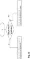
Fig. 1 ein Flussdiagramm zur Darstellung eines erfindungsgemäßen Verfahrens bis 1 bohne Festlegung von Schwenkbereichen der vertikalen Hell-Dunkel-Grenzen, -
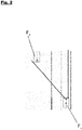
Fig. 2 eine Darstellung einer Fahrsituation in der Draufsicht, mit einer an dem vor einem Kraftfahrzeug liegenden Straßenverlauf ausgerichteter vertikalen Hell-Dunkel-Grenze des rechten Scheinwerfers und einer an dem Objekt ausgerichteter vertikalen Hell-Dunkel-Grenze des linken Scheinwerfers bei einer Geradeausfahrt des Fahrzeugs, -
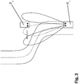
Fig. 3 eine Darstellung einer Fahrsituation in der Draufsicht, mit einer an dem vor einem Kraftfahrzeug liegenden Straßenverlauf ausgerichteter rechten vertikalen Hell-Dunkel-Grenze des linken Scheinwerfers und einer an dem Objekt ausgerichteter linken vertikalen Hell-Dunkel-Grenze des rechten Scheinwerfers bei einer Kurvenfahrt des Fahrzeugs,
-
Fig. 1 1 is a flow chart for illustrating a method according to the invention without definition of pivot ranges of the vertical light-dark boundaries; -
Fig. 2 a representation of a driving situation in the plan view, with an aligned on the lying in front of a motor vehicle roadway vertical light-dark boundary of the right headlight and a aligned on the object vertical bright-dark boundary of the left headlamp when driving straight ahead of the vehicle, -
Fig. 3 a representation of a driving situation in the plan view, with an aligned on the lying in front of a motor vehicle road right vertical cut-off of the left headlamp and a aligned on the object left vertical cut-off of the right headlamp when cornering the vehicle,
In den
Die
Dagegen sind in beiden Fahrsituationen die vertikalen Hell-Dunkel-Grenzen des bezüglich der Längsachse des Kraftfahrzeugs F1 vom Objekt abgewandten Scheinwerfers auf den weiteren Straßenverlauf ausgerichtet. In
- F1 F 1
- erstes Kraftfahrzeugfirst motor vehicle
- F2 F 2
- entgegenkommendes Fahrzeugoncoming vehicle
- II
- Längsachse des ersten KraftfahrzeugsLongitudinal axis of the first motor vehicle
Claims (3)
Applications Claiming Priority (3)
| Application Number | Priority Date | Filing Date | Title |
|---|---|---|---|
| DE102008047025A DE102008047025A1 (en) | 2008-09-13 | 2008-09-13 | Method and apparatus for controlling vertical cut-offs on headlamps within a swivel range |
| PCT/EP2009/061680 WO2010029102A1 (en) | 2008-09-13 | 2009-09-09 | Method and device for controlling vertical light-dark limits in headlights within a tilt range |
| EP09782809.9A EP2326533B1 (en) | 2008-09-13 | 2009-09-09 | Method and device for controlling vertical light-dark limits in headlights within a tilt range |
Related Parent Applications (2)
| Application Number | Title | Priority Date | Filing Date |
|---|---|---|---|
| EP09782809.9A Division EP2326533B1 (en) | 2008-09-13 | 2009-09-09 | Method and device for controlling vertical light-dark limits in headlights within a tilt range |
| EP09782809.9A Division-Into EP2326533B1 (en) | 2008-09-13 | 2009-09-09 | Method and device for controlling vertical light-dark limits in headlights within a tilt range |
Publications (2)
| Publication Number | Publication Date |
|---|---|
| EP3246207A1 true EP3246207A1 (en) | 2017-11-22 |
| EP3246207B1 EP3246207B1 (en) | 2019-02-13 |
Family
ID=41263634
Family Applications (2)
| Application Number | Title | Priority Date | Filing Date |
|---|---|---|---|
| EP09782809.9A Active EP2326533B1 (en) | 2008-09-13 | 2009-09-09 | Method and device for controlling vertical light-dark limits in headlights within a tilt range |
| EP17176935.9A Active EP3246207B1 (en) | 2008-09-13 | 2009-09-09 | Method and device for controlling vertical cut-off lines for headlights |
Family Applications Before (1)
| Application Number | Title | Priority Date | Filing Date |
|---|---|---|---|
| EP09782809.9A Active EP2326533B1 (en) | 2008-09-13 | 2009-09-09 | Method and device for controlling vertical light-dark limits in headlights within a tilt range |
Country Status (4)
| Country | Link |
|---|---|
| US (1) | US8862335B2 (en) |
| EP (2) | EP2326533B1 (en) |
| DE (1) | DE102008047025A1 (en) |
| WO (1) | WO2010029102A1 (en) |
Families Citing this family (6)
| Publication number | Priority date | Publication date | Assignee | Title |
|---|---|---|---|---|
| JP5438405B2 (en) * | 2009-07-10 | 2014-03-12 | 株式会社小糸製作所 | Vehicle headlamp device |
| DE102011002338A1 (en) * | 2011-04-29 | 2012-10-31 | Hella Kgaa Hueck & Co. | Device for controlling right and left headlamp of motor vehicle, has interface and processing unit, where control signals are produced, with which low-beam light distribution is adjusted at right headlamp |
| AT518039B1 (en) * | 2015-11-25 | 2018-02-15 | Zkw Group Gmbh | Motor vehicle headlight with a smart highway flare |
| DE102016122492A1 (en) * | 2016-11-22 | 2018-05-24 | HELLA GmbH & Co. KGaA | Generation of a homogeneous light distribution as a function of the topography and the measured luminance |
| DE102017129946A1 (en) * | 2017-12-14 | 2019-06-19 | HELLA GmbH & Co. KGaA | Method for detecting incorrect settings of the cut-off of a headlight |
| CN111268007B (en) * | 2020-02-27 | 2021-05-18 | 衢州市云端智能科技有限公司 | Motorcycle headlight follow-up steering system |
Citations (5)
| Publication number | Priority date | Publication date | Assignee | Title |
|---|---|---|---|---|
| GB1352999A (en) * | 1970-09-18 | 1974-05-15 | Lucas Industries Ltd | Road vehicle lighting systems |
| DE19602622A1 (en) * | 1995-02-07 | 1996-08-08 | Honda Motor Co Ltd | Motor vehicle headlamp arrangement |
| WO2008037388A2 (en) * | 2006-09-27 | 2008-04-03 | Volkswagen Aktiengesellschaft | Headlight arrangement for a vehicle and method for controlling a headlight arrangement |
| DE102007000600A1 (en) * | 2006-10-31 | 2008-08-07 | Denso Corp., Kariya | Device for controlling tilt angles of vehicle headlights |
| DE102008012327A1 (en) * | 2007-03-01 | 2008-09-04 | Denso Corp., Kariya | System for controlling a headlamp of a vehicle comprises a unit for determining the distance between a controlled vehicle and a vehicle in front, a unit for determining a distance for an optical axis of the headlamp and an adjusting unit |
Family Cites Families (15)
| Publication number | Priority date | Publication date | Assignee | Title |
|---|---|---|---|---|
| JP2004098970A (en) * | 2002-09-12 | 2004-04-02 | Koito Mfg Co Ltd | Headlamp device for vehicle |
| JP4131845B2 (en) * | 2003-09-29 | 2008-08-13 | 株式会社小糸製作所 | Lamp unit and vehicle headlamp |
| DE102005014953A1 (en) | 2005-04-01 | 2006-10-05 | Audi Ag | Motor vehicle with a lighting device with variable illumination volume |
| CZ302547B6 (en) * | 2005-07-04 | 2011-07-07 | Visteon Global Technologies, Inc. | Adaptive headlight system of motor vehicles |
| US8419232B2 (en) * | 2005-07-28 | 2013-04-16 | Light Prescriptions Innovators, Llc | Free-form lenticular optical elements and their application to condensers and headlamps |
| EP1757486B1 (en) * | 2005-08-26 | 2014-04-30 | Nissan Motor Co., Ltd. | Device and method for controlling vehicle headlamps |
| US7563008B2 (en) * | 2006-03-28 | 2009-07-21 | Visteon Global Technologies, Inc. | LED projector headlamps using single or multi-faceted lenses |
| JP4473232B2 (en) * | 2006-04-26 | 2010-06-02 | 株式会社日本自動車部品総合研究所 | Vehicle front environment detecting device for vehicle and lighting device for vehicle |
| JP4586777B2 (en) * | 2006-08-10 | 2010-11-24 | 市光工業株式会社 | Vehicle headlamp |
| JP4926770B2 (en) * | 2007-03-15 | 2012-05-09 | 株式会社小糸製作所 | Vehicle headlamp device |
| FR2923890A1 (en) * | 2007-11-16 | 2009-05-22 | Valeo Vision Sa | LIGHTING DEVICE FOR MOTOR VEHICLE |
| JP4995748B2 (en) * | 2008-01-29 | 2012-08-08 | 株式会社小糸製作所 | Vehicle headlamp device and control method for vehicle headlamp device |
| JP2009214812A (en) * | 2008-03-12 | 2009-09-24 | Koito Mfg Co Ltd | Vehicular headlight device and its control method |
| DE102008038536A1 (en) | 2008-08-20 | 2010-02-25 | Hella Kgaa Hueck & Co. | Method and device for controlling the vertical cut-off for headlamps |
| FR2936591B1 (en) * | 2008-09-30 | 2014-09-12 | Valeo Vision Sas | OPTICAL MODULE FOR A MOTOR VEHICLE FOR SELECTIVELY LIGHTING A ZONE |
-
2008
- 2008-09-13 DE DE102008047025A patent/DE102008047025A1/en not_active Withdrawn
-
2009
- 2009-09-09 WO PCT/EP2009/061680 patent/WO2010029102A1/en active Application Filing
- 2009-09-09 US US13/063,728 patent/US8862335B2/en active Active
- 2009-09-09 EP EP09782809.9A patent/EP2326533B1/en active Active
- 2009-09-09 EP EP17176935.9A patent/EP3246207B1/en active Active
Patent Citations (5)
| Publication number | Priority date | Publication date | Assignee | Title |
|---|---|---|---|---|
| GB1352999A (en) * | 1970-09-18 | 1974-05-15 | Lucas Industries Ltd | Road vehicle lighting systems |
| DE19602622A1 (en) * | 1995-02-07 | 1996-08-08 | Honda Motor Co Ltd | Motor vehicle headlamp arrangement |
| WO2008037388A2 (en) * | 2006-09-27 | 2008-04-03 | Volkswagen Aktiengesellschaft | Headlight arrangement for a vehicle and method for controlling a headlight arrangement |
| DE102007000600A1 (en) * | 2006-10-31 | 2008-08-07 | Denso Corp., Kariya | Device for controlling tilt angles of vehicle headlights |
| DE102008012327A1 (en) * | 2007-03-01 | 2008-09-04 | Denso Corp., Kariya | System for controlling a headlamp of a vehicle comprises a unit for determining the distance between a controlled vehicle and a vehicle in front, a unit for determining a distance for an optical axis of the headlamp and an adjusting unit |
Also Published As
| Publication number | Publication date |
|---|---|
| WO2010029102A1 (en) | 2010-03-18 |
| EP3246207B1 (en) | 2019-02-13 |
| US20110295471A1 (en) | 2011-12-01 |
| EP2326533B1 (en) | 2017-10-25 |
| US8862335B2 (en) | 2014-10-14 |
| DE102008047025A1 (en) | 2010-03-18 |
| EP2326533A1 (en) | 2011-06-01 |
Similar Documents
| Publication | Publication Date | Title |
|---|---|---|
| EP2156983B1 (en) | Method and device for controlling the vertical cut-off line of headlamps | |
| DE19716784B4 (en) | Headlamp system for vehicles | |
| EP3033248B1 (en) | Method for controlling a headlight arrangement for a vehicle and such a headlight arrangement | |
| EP3246207B1 (en) | Method and device for controlling vertical cut-off lines for headlights | |
| EP2156984B1 (en) | Method and device for controlling the vertical cut-off line of headlamps | |
| DE102008011699A1 (en) | Characteristics e.g. elevation of headlight, determining method for e.g. automobile, involves detecting image having patterns by image detecting device, and determining characteristics e.g. brightness and/or contrast, from patterns | |
| EP2119592A1 (en) | Control device to control vehicle's main headlights | |
| DE102009057391A1 (en) | Method for driving light control of vehicle, involves adjusting left swivel head light and right swivel head light independently to each other for adjustment of light distribution | |
| DE102014113478A1 (en) | Lighting device of a motor vehicle and method for operating a lighting device | |
| DE102014204791A1 (en) | Automatic control of the headlights of a vehicle | |
| AT517415B1 (en) | Control device for a lighting device of a motor vehicle and method for controlling such a lighting device | |
| DE102010035636A1 (en) | Device and method for changing from a high beam distribution to an object to blinding blinding light distribution | |
| DE102008034166A1 (en) | Method and device for Euting a suitable light distribution of the light emitted by at least one headlight of a vehicle light | |
| EP2596990B1 (en) | Method and controller for controlling main headlights with adjustable light/dark limit for preventing glare from objects | |
| DE102017121662B4 (en) | Arrangement and method for producing asymmetrical, glare-free high beam | |
| DE102012106502A1 (en) | Device for warning motor car operator of hazard location in traffic space, has high-beam headlamps that is set based on detected hazardous areas and headlamp control information to control illumination of traffic space | |
| DE102013109071A1 (en) | Arrangement and method for blinding vehicles with the aid of at least one near field sensor device | |
| DE102016208831B4 (en) | Method and device for driving light control | |
| EP2119593A1 (en) | Control device to control and/or regulate a vertical cut-off line for a vehicle's headlights | |
| EP2576290B1 (en) | Control unit and method for preventing dazzling of vehicles during turning manoeuvres | |
| WO2009053457A1 (en) | Device for controlling and/or regulating the activation or deactivation of the automatic setting of the light-dark boundary of a motor vehicle headlight or turning the high beams on and off in motor vehicle headlights | |
| DE102014006598A1 (en) | Method for operating a driver assistance system of a motor vehicle, driver assistance system and motor vehicle | |
| DE102004022813B4 (en) | Motor vehicle headlamps | |
| DE202010001654U1 (en) | Lighting system for a motor vehicle | |
| DE102018200005B4 (en) | Street topography adaptation of the lamps of a motor vehicle |
Legal Events
| Date | Code | Title | Description |
|---|---|---|---|
| PUAI | Public reference made under article 153(3) epc to a published international application that has entered the european phase |
Free format text: ORIGINAL CODE: 0009012 |
|
| STAA | Information on the status of an ep patent application or granted ep patent |
Free format text: STATUS: THE APPLICATION HAS BEEN PUBLISHED |
|
| AC | Divisional application: reference to earlier application |
Ref document number: 2326533 Country of ref document: EP Kind code of ref document: P |
|
| AK | Designated contracting states |
Kind code of ref document: A1 Designated state(s): AT BE BG CH CY CZ DE DK EE ES FI FR GB GR HR HU IE IS IT LI LT LU LV MC MK MT NL NO PL PT RO SE SI SK SM TR |
|
| RAP1 | Party data changed (applicant data changed or rights of an application transferred) |
Owner name: HELLA GMBH & CO. KGAA |
|
| STAA | Information on the status of an ep patent application or granted ep patent |
Free format text: STATUS: REQUEST FOR EXAMINATION WAS MADE |
|
| 17P | Request for examination filed |
Effective date: 20171207 |
|
| RBV | Designated contracting states (corrected) |
Designated state(s): AT BE BG CH CY CZ DE DK EE ES FI FR GB GR HR HU IE IS IT LI LT LU LV MC MK MT NL NO PL PT RO SE SI SK SM TR |
|
| GRAP | Despatch of communication of intention to grant a patent |
Free format text: ORIGINAL CODE: EPIDOSNIGR1 |
|
| STAA | Information on the status of an ep patent application or granted ep patent |
Free format text: STATUS: GRANT OF PATENT IS INTENDED |
|
| INTG | Intention to grant announced |
Effective date: 20180928 |
|
| GRAS | Grant fee paid |
Free format text: ORIGINAL CODE: EPIDOSNIGR3 |
|
| GRAA | (expected) grant |
Free format text: ORIGINAL CODE: 0009210 |
|
| STAA | Information on the status of an ep patent application or granted ep patent |
Free format text: STATUS: THE PATENT HAS BEEN GRANTED |
|
| AC | Divisional application: reference to earlier application |
Ref document number: 2326533 Country of ref document: EP Kind code of ref document: P |
|
| AK | Designated contracting states |
Kind code of ref document: B1 Designated state(s): AT BE BG CH CY CZ DE DK EE ES FI FR GB GR HR HU IE IS IT LI LT LU LV MC MK MT NL NO PL PT RO SE SI SK SM TR |
|
| REG | Reference to a national code |
Ref country code: GB Ref legal event code: FG4D Free format text: NOT ENGLISH |
|
| REG | Reference to a national code |
Ref country code: CH Ref legal event code: EP Ref country code: AT Ref legal event code: REF Ref document number: 1096001 Country of ref document: AT Kind code of ref document: T Effective date: 20190215 |
|
| REG | Reference to a national code |
Ref country code: IE Ref legal event code: FG4D Free format text: LANGUAGE OF EP DOCUMENT: GERMAN |
|
| REG | Reference to a national code |
Ref country code: DE Ref legal event code: R096 Ref document number: 502009015619 Country of ref document: DE |
|
| REG | Reference to a national code |
Ref country code: LT Ref legal event code: MG4D |
|
| REG | Reference to a national code |
Ref country code: NL Ref legal event code: MP Effective date: 20190213 |
|
| PG25 | Lapsed in a contracting state [announced via postgrant information from national office to epo] |
Ref country code: LT Free format text: LAPSE BECAUSE OF FAILURE TO SUBMIT A TRANSLATION OF THE DESCRIPTION OR TO PAY THE FEE WITHIN THE PRESCRIBED TIME-LIMIT Effective date: 20190213 Ref country code: NL Free format text: LAPSE BECAUSE OF FAILURE TO SUBMIT A TRANSLATION OF THE DESCRIPTION OR TO PAY THE FEE WITHIN THE PRESCRIBED TIME-LIMIT Effective date: 20190213 Ref country code: SE Free format text: LAPSE BECAUSE OF FAILURE TO SUBMIT A TRANSLATION OF THE DESCRIPTION OR TO PAY THE FEE WITHIN THE PRESCRIBED TIME-LIMIT Effective date: 20190213 Ref country code: PT Free format text: LAPSE BECAUSE OF FAILURE TO SUBMIT A TRANSLATION OF THE DESCRIPTION OR TO PAY THE FEE WITHIN THE PRESCRIBED TIME-LIMIT Effective date: 20190613 Ref country code: NO Free format text: LAPSE BECAUSE OF FAILURE TO SUBMIT A TRANSLATION OF THE DESCRIPTION OR TO PAY THE FEE WITHIN THE PRESCRIBED TIME-LIMIT Effective date: 20190513 Ref country code: FI Free format text: LAPSE BECAUSE OF FAILURE TO SUBMIT A TRANSLATION OF THE DESCRIPTION OR TO PAY THE FEE WITHIN THE PRESCRIBED TIME-LIMIT Effective date: 20190213 |
|
| PG25 | Lapsed in a contracting state [announced via postgrant information from national office to epo] |
Ref country code: IS Free format text: LAPSE BECAUSE OF FAILURE TO SUBMIT A TRANSLATION OF THE DESCRIPTION OR TO PAY THE FEE WITHIN THE PRESCRIBED TIME-LIMIT Effective date: 20190613 Ref country code: BG Free format text: LAPSE BECAUSE OF FAILURE TO SUBMIT A TRANSLATION OF THE DESCRIPTION OR TO PAY THE FEE WITHIN THE PRESCRIBED TIME-LIMIT Effective date: 20190513 Ref country code: LV Free format text: LAPSE BECAUSE OF FAILURE TO SUBMIT A TRANSLATION OF THE DESCRIPTION OR TO PAY THE FEE WITHIN THE PRESCRIBED TIME-LIMIT Effective date: 20190213 Ref country code: GR Free format text: LAPSE BECAUSE OF FAILURE TO SUBMIT A TRANSLATION OF THE DESCRIPTION OR TO PAY THE FEE WITHIN THE PRESCRIBED TIME-LIMIT Effective date: 20190514 Ref country code: HR Free format text: LAPSE BECAUSE OF FAILURE TO SUBMIT A TRANSLATION OF THE DESCRIPTION OR TO PAY THE FEE WITHIN THE PRESCRIBED TIME-LIMIT Effective date: 20190213 |
|
| PG25 | Lapsed in a contracting state [announced via postgrant information from national office to epo] |
Ref country code: ES Free format text: LAPSE BECAUSE OF FAILURE TO SUBMIT A TRANSLATION OF THE DESCRIPTION OR TO PAY THE FEE WITHIN THE PRESCRIBED TIME-LIMIT Effective date: 20190213 Ref country code: DK Free format text: LAPSE BECAUSE OF FAILURE TO SUBMIT A TRANSLATION OF THE DESCRIPTION OR TO PAY THE FEE WITHIN THE PRESCRIBED TIME-LIMIT Effective date: 20190213 Ref country code: SK Free format text: LAPSE BECAUSE OF FAILURE TO SUBMIT A TRANSLATION OF THE DESCRIPTION OR TO PAY THE FEE WITHIN THE PRESCRIBED TIME-LIMIT Effective date: 20190213 Ref country code: EE Free format text: LAPSE BECAUSE OF FAILURE TO SUBMIT A TRANSLATION OF THE DESCRIPTION OR TO PAY THE FEE WITHIN THE PRESCRIBED TIME-LIMIT Effective date: 20190213 Ref country code: IT Free format text: LAPSE BECAUSE OF FAILURE TO SUBMIT A TRANSLATION OF THE DESCRIPTION OR TO PAY THE FEE WITHIN THE PRESCRIBED TIME-LIMIT Effective date: 20190213 Ref country code: CZ Free format text: LAPSE BECAUSE OF FAILURE TO SUBMIT A TRANSLATION OF THE DESCRIPTION OR TO PAY THE FEE WITHIN THE PRESCRIBED TIME-LIMIT Effective date: 20190213 Ref country code: RO Free format text: LAPSE BECAUSE OF FAILURE TO SUBMIT A TRANSLATION OF THE DESCRIPTION OR TO PAY THE FEE WITHIN THE PRESCRIBED TIME-LIMIT Effective date: 20190213 |
|
| REG | Reference to a national code |
Ref country code: DE Ref legal event code: R097 Ref document number: 502009015619 Country of ref document: DE |
|
| PG25 | Lapsed in a contracting state [announced via postgrant information from national office to epo] |
Ref country code: SM Free format text: LAPSE BECAUSE OF FAILURE TO SUBMIT A TRANSLATION OF THE DESCRIPTION OR TO PAY THE FEE WITHIN THE PRESCRIBED TIME-LIMIT Effective date: 20190213 Ref country code: PL Free format text: LAPSE BECAUSE OF FAILURE TO SUBMIT A TRANSLATION OF THE DESCRIPTION OR TO PAY THE FEE WITHIN THE PRESCRIBED TIME-LIMIT Effective date: 20190213 |
|
| PLBE | No opposition filed within time limit |
Free format text: ORIGINAL CODE: 0009261 |
|
| STAA | Information on the status of an ep patent application or granted ep patent |
Free format text: STATUS: NO OPPOSITION FILED WITHIN TIME LIMIT |
|
| 26N | No opposition filed |
Effective date: 20191114 |
|
| PG25 | Lapsed in a contracting state [announced via postgrant information from national office to epo] |
Ref country code: SI Free format text: LAPSE BECAUSE OF FAILURE TO SUBMIT A TRANSLATION OF THE DESCRIPTION OR TO PAY THE FEE WITHIN THE PRESCRIBED TIME-LIMIT Effective date: 20190213 |
|
| PG25 | Lapsed in a contracting state [announced via postgrant information from national office to epo] |
Ref country code: TR Free format text: LAPSE BECAUSE OF FAILURE TO SUBMIT A TRANSLATION OF THE DESCRIPTION OR TO PAY THE FEE WITHIN THE PRESCRIBED TIME-LIMIT Effective date: 20190213 |
|
| PG25 | Lapsed in a contracting state [announced via postgrant information from national office to epo] |
Ref country code: MC Free format text: LAPSE BECAUSE OF FAILURE TO SUBMIT A TRANSLATION OF THE DESCRIPTION OR TO PAY THE FEE WITHIN THE PRESCRIBED TIME-LIMIT Effective date: 20190213 |
|
| REG | Reference to a national code |
Ref country code: CH Ref legal event code: PL |
|
| PG25 | Lapsed in a contracting state [announced via postgrant information from national office to epo] |
Ref country code: LI Free format text: LAPSE BECAUSE OF NON-PAYMENT OF DUE FEES Effective date: 20190930 Ref country code: LU Free format text: LAPSE BECAUSE OF NON-PAYMENT OF DUE FEES Effective date: 20190909 Ref country code: IE Free format text: LAPSE BECAUSE OF NON-PAYMENT OF DUE FEES Effective date: 20190909 Ref country code: CH Free format text: LAPSE BECAUSE OF NON-PAYMENT OF DUE FEES Effective date: 20190930 |
|
| REG | Reference to a national code |
Ref country code: BE Ref legal event code: MM Effective date: 20190930 |
|
| PG25 | Lapsed in a contracting state [announced via postgrant information from national office to epo] |
Ref country code: BE Free format text: LAPSE BECAUSE OF NON-PAYMENT OF DUE FEES Effective date: 20190930 |
|
| GBPC | Gb: european patent ceased through non-payment of renewal fee |
Effective date: 20190909 |
|
| PG25 | Lapsed in a contracting state [announced via postgrant information from national office to epo] |
Ref country code: GB Free format text: LAPSE BECAUSE OF NON-PAYMENT OF DUE FEES Effective date: 20190909 |
|
| REG | Reference to a national code |
Ref country code: AT Ref legal event code: MM01 Ref document number: 1096001 Country of ref document: AT Kind code of ref document: T Effective date: 20190909 |
|
| PG25 | Lapsed in a contracting state [announced via postgrant information from national office to epo] |
Ref country code: AT Free format text: LAPSE BECAUSE OF NON-PAYMENT OF DUE FEES Effective date: 20190909 |
|
| PG25 | Lapsed in a contracting state [announced via postgrant information from national office to epo] |
Ref country code: CY Free format text: LAPSE BECAUSE OF FAILURE TO SUBMIT A TRANSLATION OF THE DESCRIPTION OR TO PAY THE FEE WITHIN THE PRESCRIBED TIME-LIMIT Effective date: 20190213 |
|
| PG25 | Lapsed in a contracting state [announced via postgrant information from national office to epo] |
Ref country code: HU Free format text: LAPSE BECAUSE OF FAILURE TO SUBMIT A TRANSLATION OF THE DESCRIPTION OR TO PAY THE FEE WITHIN THE PRESCRIBED TIME-LIMIT; INVALID AB INITIO Effective date: 20090909 Ref country code: MT Free format text: LAPSE BECAUSE OF FAILURE TO SUBMIT A TRANSLATION OF THE DESCRIPTION OR TO PAY THE FEE WITHIN THE PRESCRIBED TIME-LIMIT Effective date: 20190213 |
|
| PG25 | Lapsed in a contracting state [announced via postgrant information from national office to epo] |
Ref country code: MK Free format text: LAPSE BECAUSE OF FAILURE TO SUBMIT A TRANSLATION OF THE DESCRIPTION OR TO PAY THE FEE WITHIN THE PRESCRIBED TIME-LIMIT Effective date: 20190213 |
|
| PGFP | Annual fee paid to national office [announced via postgrant information from national office to epo] |
Ref country code: FR Payment date: 20230703 Year of fee payment: 15 Ref country code: DE Payment date: 20230718 Year of fee payment: 15 |