EP3246120A1 - Metal-boring tool - Google Patents
Metal-boring tool Download PDFInfo
- Publication number
- EP3246120A1 EP3246120A1 EP16170048.9A EP16170048A EP3246120A1 EP 3246120 A1 EP3246120 A1 EP 3246120A1 EP 16170048 A EP16170048 A EP 16170048A EP 3246120 A1 EP3246120 A1 EP 3246120A1
- Authority
- EP
- European Patent Office
- Prior art keywords
- blind hole
- cutting edge
- shaft
- drilling
- rotation
- Prior art date
- Legal status (The legal status is an assumption and is not a legal conclusion. Google has not performed a legal analysis and makes no representation as to the accuracy of the status listed.)
- Withdrawn
Links
Images
Classifications
-
- B—PERFORMING OPERATIONS; TRANSPORTING
- B23—MACHINE TOOLS; METAL-WORKING NOT OTHERWISE PROVIDED FOR
- B23B—TURNING; BORING
- B23B51/00—Tools for drilling machines
- B23B51/02—Twist drills
-
- B—PERFORMING OPERATIONS; TRANSPORTING
- B23—MACHINE TOOLS; METAL-WORKING NOT OTHERWISE PROVIDED FOR
- B23B—TURNING; BORING
- B23B51/00—Tools for drilling machines
- B23B51/10—Bits for countersinking
- B23B51/107—Bits for countersinking having a pilot
-
- B—PERFORMING OPERATIONS; TRANSPORTING
- B23—MACHINE TOOLS; METAL-WORKING NOT OTHERWISE PROVIDED FOR
- B23B—TURNING; BORING
- B23B2251/00—Details of tools for drilling machines
- B23B2251/24—Overall form of drilling tools
- B23B2251/241—Cross sections of the diameter of the drill
- B23B2251/244—Cross sections of the diameter of the drill decreasing in a direction towards the shank from the tool tip
-
- B—PERFORMING OPERATIONS; TRANSPORTING
- B23—MACHINE TOOLS; METAL-WORKING NOT OTHERWISE PROVIDED FOR
- B23B—TURNING; BORING
- B23B2251/00—Details of tools for drilling machines
- B23B2251/52—Depth indicators
-
- B—PERFORMING OPERATIONS; TRANSPORTING
- B23—MACHINE TOOLS; METAL-WORKING NOT OTHERWISE PROVIDED FOR
- B23B—TURNING; BORING
- B23B51/00—Tools for drilling machines
- B23B51/10—Bits for countersinking
- B23B51/105—Deburring or countersinking of radial holes
-
- Y—GENERAL TAGGING OF NEW TECHNOLOGICAL DEVELOPMENTS; GENERAL TAGGING OF CROSS-SECTIONAL TECHNOLOGIES SPANNING OVER SEVERAL SECTIONS OF THE IPC; TECHNICAL SUBJECTS COVERED BY FORMER USPC CROSS-REFERENCE ART COLLECTIONS [XRACs] AND DIGESTS
- Y10—TECHNICAL SUBJECTS COVERED BY FORMER USPC
- Y10T—TECHNICAL SUBJECTS COVERED BY FORMER US CLASSIFICATION
- Y10T408/00—Cutting by use of rotating axially moving tool
- Y10T408/89—Tool or Tool with support
- Y10T408/909—Having peripherally spaced cutting edges
- Y10T408/9095—Having peripherally spaced cutting edges with axially extending relief channel
- Y10T408/9097—Spiral channel
Definitions
- the present invention relates to a drill for hand-guided drilling of a blind hole in a workpiece made of metal.
- drills which have a drilling direction defining a shaft with a cutting edge and a stop shoulder whose distance from one another defines a blind hole depth.
- the shaft usually has an enveloping circle diameter between the cutting edge and the stop shoulder, which is as large as a blind-hole diameter defined by the cutting edge.
- the drill is unintentionally pivoted so that the shaft expands or damages the blind hole during drilling.
- the invention is based on the object to provide a drill with which the risk of expansion or damage of the blind hole is reduced.
- a drill for hand-guided drilling of a blind hole with a blind hole diameter and a blind hole depth in a workpiece made of metal comprising a shaft which defines a drilling direction and has an axis of rotation oriented in the drilling direction, wherein the shaft pointing at its in the drilling direction End having a cutting edge and in a Sackloch depth defining and counter to the drilling direction measured distance to the cutting edge has a stop shoulder, wherein the cutting edge defined by rotation about the axis of rotation of the blind hole diameter, the shaft having a along the axis of rotation changing enveloping diameter, which at the stop shoulder larger as the blind hole diameter, wherein the shaft has a first shaft portion arranged between the cutting edge and the stop shoulder, which reaches as far as the stop shoulder and in which the envelope circle diameter is smaller than the blind hole diameter is.
- the shaft preferably has two or more cutting edges at its end pointing in the drilling direction, which define the blind hole diameter jointly by rotation about the axis of rotation and are particularly preferably arranged symmetric
- a Hüll réelle malmesser according to the invention is the diameter of the smallest possible circle, which still completely envelopes the shaft with a circle center on the axis of rotation.
- the circular area of the enveloping circle is the area covered by the shaft when rotated about the axis of rotation.
- the enveloping circle diameter is equal to the diameter of the circumferential line, that is to say the shaft diameter. Deviations of the circumferential line from the circular shape to the inside do not influence the envelope circle diameter, while deviations to the outside, on the other hand, increase the envelope circle diameter.
- the shank has a second shank portion arranged between the cutting edge and the first shank portion, which reaches up to the cutting edge and in which the sheath circle diameter is constant and the same size as the blind hole diameter.
- the second shaft section extends to the first shaft section.
- the first shaft portion reaches the cutting edge.
- the first shaft portion and the cutting edge are made of the same material and are formed integrally with each other.
- the enveloping circle diameter increases in the first shaft portion in regions, particularly preferably continuously, in the drilling direction.
- the enveloping circle diameter increases linearly in the first shaft section, whereby a conical enveloping surface is formed.
- the conical envelope surface is inclined relative to the drilling direction by a cone angle, which is preferably between 2 ° and 10 ° and particularly preferably at least 5 °.
- the enveloping circle diameter in the first shank portion is in regions, particularly preferably continuously, constant, whereby a circular cylindrical envelope surface is formed.
- the shaft has at its pointing in the direction of drilling end a centering tip through which passes the axis of rotation.
- the stop shoulder on a perpendicular to the axis of rotation aligned and pointing in the direction of drilling stop surface.
- the shaft at its opposite the drilling direction end facing a mounting portion for a temporary attachment a hand-held drill on.
- the attachment portion is designed as a plug-in end.
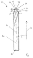
- the figure shows a drill 10, which is suitable for hand-guided drilling a blind hole in a non-illustrated workpiece made of metal, in a side view.
- the drill 10 comprises a shaft 20 which defines a drilling direction 30 and has an axis of rotation 40 oriented in the drilling direction 30.
- end of the shaft 20 has a cutting edge 50 and a further cutting edge, not shown, which are arranged opposite to each other and symmetrical with respect to the rotation axis 40 and define by rotation about the rotation axis 40 together a blind hole diameter of the drilled blind hole ,
- the shaft 20 has a stop shoulder 55 with a stop surface 60 aligned perpendicular to the axis of rotation 40 and pointing in the direction of drilling 30.
- the stop shoulder 55 abuts against a surface of the workpiece, so that the distance of the stop surface 60 from the cutting edge 50 measured counter to the drilling direction 30 defines a blind hole depth of the drilled blind hole.
- the shaft 20 has a male end 80 for temporary attachment to a hand-held drill.
- the shaft 20 has an enveloping circle diameter changing along the axis of rotation 40.
- first shaft portion 41 of the shaft 40 of the enveloping circle diameter d1 is smaller than the blind hole diameter.
- second shaft portion 42 of the shaft 40 of the enveloping circle diameter d2 is constant and the same size as the blind hole diameter.
- the enveloping circle diameter d3 is greater than the blind hole diameter.
- the enveloping circle diameter d1 in the first shaft section 41 increases continuously in the drilling direction 30, so that a conical enveloping surface is formed.
- the conical envelope surface is inclined relative to the drilling direction 30 by a cone angle ⁇ , which is 5 °.
- the enveloping circle diameter d2 in the second shaft section 42 is constant throughout, so that a circular-cylindrical envelope surface is formed, which may protect the cutting edge 50 from excessive wear.
- the shaft 20 at its pointing in the direction of drilling 30 end a centering tip 70 through which the axis of rotation 40 extends.
- the entire shaft 40 including the cutting edge 50 and the centering tip 70 is formed in one piece, so that the stop shoulder 55, the first shaft portion 41, the second shaft portion 42 and the cutting edge 50 of the same material, preferably a metal or alloy, particularly preferred a steel.
- the shank 20 has two helical grooves 90, which extend through the stop shoulder 55, the first shank portion 41 and the second shank portion 42, and of the cutting edge 50 and are limited by the other cutting edge.
Landscapes
- Engineering & Computer Science (AREA)
- Mechanical Engineering (AREA)
- Drilling Tools (AREA)
- Earth Drilling (AREA)
Abstract
Bohrer zum handgeführten Bohren eines Sacklochs mit einem Sacklochdurchmesser und einer Sacklochtiefe in ein Werkstück aus Metall, umfassend einen Schaft, welcher eine Bohrrichtung definiert und eine in der Bohrrichtung orientierte Drehachse aufweist, wobei der Schaft an seinem in die Bohrrichtung weisenden Ende eine Schneidkante und in einem die Sacklochtiefe definierenden Abstand zur Schneidkante eine Anschlagschulter aufweist, wobei die Schneidkante durch Drehung um die Drehachse den Sacklochdurchmesser definiert, wobei der Schaft einen sich entlang der Drehachse ändernden Hüllkreisdurchmesser aufweist, welcher an der Anschlagschulter grösser als der Sacklochdurchmesser ist, wobei der Schaft einen zwischen der Schneidkante und der Anschlagschulter angeordneten ersten Schaftabschnitt aufweist, welcher bis an die Anschlagschulter heranreicht und in welchem der Hüllkreisdurchmesser kleiner als der Sacklochdurchmesser ist.A drill bit for hand-guided drilling of a blind hole having a blind hole diameter and a blind hole depth into a workpiece made of metal, comprising a shank defining a drilling direction and having an axis of rotation oriented in the drilling direction, the shank having a cutting edge at its end pointing in the drilling direction and a shank the blind hole depth defining distance to the cutting edge has a stop shoulder, wherein the cutting edge defined by rotation about the axis of rotation of the blind hole diameter, wherein the shaft has a changing axis along the axis of rotation envelope diameter, which is greater than the blind hole diameter at the stop shoulder, wherein the shaft one between the Cutting edge and the stop shoulder has arranged first shaft portion which extends to the stop shoulder and in which the envelope circle diameter is smaller than the blind hole diameter.
Description
Die vorliegende Erfindung betrifft einen Bohrer zum handgeführten Bohren eines Sacklochs in ein Werkstück aus Metall.The present invention relates to a drill for hand-guided drilling of a blind hole in a workpiece made of metal.
Es sind Bohrer bekannt, welche einen eine Bohrrichtung definierenden Schaft mit einer Schneidkante und einer Anschlagschulter aufweisen, deren Abstand zueinander eine Sacklochtiefe definiert. Üblicherweise weist der Schaft zwischen der Schneidkante und der Anschlagschulter einen Hüllkreisdurchmesser auf, welcher so gross wie ein von der Schneidkante definierter Sacklochdurchmesser ist. Bei einem handgeführten Bohren kommt es vor, dass der Bohrer unabsichtlich verschwenkt wird, so dass der Schaft das Sackloch während des Bohrens aufweitet oder beschädigt.There are drills known which have a drilling direction defining a shaft with a cutting edge and a stop shoulder whose distance from one another defines a blind hole depth. The shaft usually has an enveloping circle diameter between the cutting edge and the stop shoulder, which is as large as a blind-hole diameter defined by the cutting edge. In a hand-held drilling, it happens that the drill is unintentionally pivoted so that the shaft expands or damages the blind hole during drilling.
Der Erfindung liegt die Aufgabe zu Grunde, einen Bohrer zur Verfügung zu stellen, mit dem die Gefahr der Aufweitung oder Beschädigung des Sacklochs reduziert ist.The invention is based on the object to provide a drill with which the risk of expansion or damage of the blind hole is reduced.
Die Aufgabe ist gelöst bei einem Bohrer zum handgeführten Bohren eines Sacklochs mit einem Sacklochdurchmesser und einer Sacklochtiefe in ein Werkstück aus Metall, umfassend einen Schaft, welcher eine Bohrrichtung definiert und eine in der Bohrrichtung orientierte Drehachse aufweist, wobei der Schaft an seinem in die Bohrrichtung weisenden Ende eine Schneidkante und in einem die Sacklochtiefe definierenden und entgegen die Bohrrichtung gemessenen Abstand zur Schneidkante eine Anschlagschulter aufweist, wobei die Schneidkante durch Drehung um die Drehachse den Sacklochdurchmesser definiert, wobei der Schaft einen sich entlang der Drehachse ändernden Hüllkreisdurchmesser aufweist, welcher an der Anschlagschulter grösser als der Sacklochdurchmesser ist, wobei der Schaft einen zwischen der Schneidkante und der Anschlagschulter angeordneten ersten Schaftabschnitt aufweist, welcher bis an die Anschlagschulter heranreicht und in welchem der Hüllkreisdurchmesser kleiner als der Sacklochdurchmesser ist. Bevorzugt weist der Schaft an seinem in die Bohrrichtung weisenden Ende zwei oder mehr Schneidkanten auf, welch durch Drehung um die Drehachse den Sacklochdurchmesser gemeinsam definieren und besonders bevorzugt symmetrisch um die Drehachse angeordnet sind.The object is achieved with a drill for hand-guided drilling of a blind hole with a blind hole diameter and a blind hole depth in a workpiece made of metal, comprising a shaft which defines a drilling direction and has an axis of rotation oriented in the drilling direction, wherein the shaft pointing at its in the drilling direction End having a cutting edge and in a Sackloch depth defining and counter to the drilling direction measured distance to the cutting edge has a stop shoulder, wherein the cutting edge defined by rotation about the axis of rotation of the blind hole diameter, the shaft having a along the axis of rotation changing enveloping diameter, which at the stop shoulder larger as the blind hole diameter, wherein the shaft has a first shaft portion arranged between the cutting edge and the stop shoulder, which reaches as far as the stop shoulder and in which the envelope circle diameter is smaller than the blind hole diameter is. The shaft preferably has two or more cutting edges at its end pointing in the drilling direction, which define the blind hole diameter jointly by rotation about the axis of rotation and are particularly preferably arranged symmetrically about the axis of rotation.
Ein Hüllkreisdurchmesser im Sinne der Erfindung ist der Durchmesser des kleinstmöglichen Kreises, welcher mit einem Kreismittelpunkt auf der Drehachse den Schaft noch vollständig umhüllt. Mit anderen Worten, für jeden Punkt entlang der Drehachse ist die Kreisfläche des Hüllkreises ist die Fläche, welche der Schaft bei Drehung um die Drehachse überdeckt. Bei einer kreisförmigen Umfangslinie ist der Hüllkreisdurchmesser gleich dem Durchmesser der Umfangslinie, also dem Schaftdurchmesser. Abweichungen der Umfangslinie von der Kreisform nach innen beeinflussen den Hüllkreisdurchmesser nicht, Abweichungen nach aussen vergrössern dagegen den Hüllkreisdurchmesser.A Hüllkreisdurchmesser according to the invention is the diameter of the smallest possible circle, which still completely envelopes the shaft with a circle center on the axis of rotation. In other words, for each point along the axis of rotation, the circular area of the enveloping circle is the area covered by the shaft when rotated about the axis of rotation. In the case of a circular circumferential line, the enveloping circle diameter is equal to the diameter of the circumferential line, that is to say the shaft diameter. Deviations of the circumferential line from the circular shape to the inside do not influence the envelope circle diameter, while deviations to the outside, on the other hand, increase the envelope circle diameter.
Bei einer bevorzugten Ausführungsform weist der Schaft einen zwischen der Schneidkante und dem ersten Schaftabschnitt angeordneten zweiten Schaftabschnitt auf, welcher bis an die Schneidkante heranreicht und in welchem der Hüllkreisdurchmesser konstant und gleich gross wie der Sacklochdurchmesser ist. Besonders bevorzugt reicht der zweite Schaftabschnitt an den ersten Schaftabschnitt heran.In a preferred embodiment, the shank has a second shank portion arranged between the cutting edge and the first shank portion, which reaches up to the cutting edge and in which the sheath circle diameter is constant and the same size as the blind hole diameter. Particularly preferably, the second shaft section extends to the first shaft section.
Bei einer bevorzugten Ausführungsform reicht der erste Schaftabschnitt an die Schneidkante heran.In a preferred embodiment, the first shaft portion reaches the cutting edge.
Bei einer bevorzugten Ausführungsform bestehen der erste Schaftabschnitt und die Schneidkante aus demselben Material und sind miteinander einstückig ausgebildet.In a preferred embodiment, the first shaft portion and the cutting edge are made of the same material and are formed integrally with each other.
Bei einer bevorzugten Ausführungsform steigt der Hüllkreisdurchmesser in dem ersten Schaftabschnitt bereichsweise, besonders bevorzugt durchgehend, in der Bohrrichtung an. Besonders bevorzugt steigt der Hüllkreisdurchmesser in dem ersten Schaftabschnitt linear an, wodurch eine konische Hüllfläche gebildet ist. Die konische Hüllfläche ist gegenüber der Bohrrichtung um einen Konuswinkel geneigt, welcher bevorzugt zwischen 2° und 10° und besonders bevorzugt mindestens 5° beträgt.In a preferred embodiment, the enveloping circle diameter increases in the first shaft portion in regions, particularly preferably continuously, in the drilling direction. Particularly preferably, the enveloping circle diameter increases linearly in the first shaft section, whereby a conical enveloping surface is formed. The conical envelope surface is inclined relative to the drilling direction by a cone angle, which is preferably between 2 ° and 10 ° and particularly preferably at least 5 °.
Bei einer bevorzugten Ausführungsform ist der Hüllkreisdurchmesser in dem ersten Schaftabschnitt bereichsweise, besonders bevorzugt durchgehend, konstant, wodurch eine kreiszylindrische Hüllfläche gebildet ist.In a preferred embodiment, the enveloping circle diameter in the first shank portion is in regions, particularly preferably continuously, constant, whereby a circular cylindrical envelope surface is formed.
Bei einer bevorzugten Ausführungsform weist der Schaft an seinem in die Bohrrichtung weisenden Ende eine Zentrierspitze auf, durch welche die Drehachse verläuft.In a preferred embodiment, the shaft has at its pointing in the direction of drilling end a centering tip through which passes the axis of rotation.
Bei einer bevorzugten Ausführungsform weist die Anschlagschulter eine senkrecht zur Drehachse ausgerichtete und in die Bohrrichtung weisende Anschlagfläche auf.In a preferred embodiment, the stop shoulder on a perpendicular to the axis of rotation aligned and pointing in the direction of drilling stop surface.
Bei einer bevorzugten Ausführungsform weist der Schaft an seinem entgegen die Bohrrichtung weisenden Ende einen Befestigungsabschnitt für eine vorübergehende Befestigung an einer handgeführten Bohrmaschine auf. Besonders bevorzugt ist der Befestigungsabschnitt als Einsteckende ausgebildet.In a preferred embodiment, the shaft at its opposite the drilling direction end facing a mounting portion for a temporary attachment a hand-held drill on. Particularly preferably, the attachment portion is designed as a plug-in end.
Die Erfindung wird im Folgenden unter Bezugnahme auf die Zeichnung näher erläutert.The invention will be explained in more detail below with reference to the drawing.
Die Figur zeigt einen Bohrer 10, welcher sich zum handgeführten Bohren eines Sacklochs in ein nicht dargestelltes Werkstück aus Metall eignet, in einer Seitenansicht. Der Bohrer 10 umfasst einen Schaft 20, welcher eine Bohrrichtung 30 definiert und eine in der Bohrrichtung 30 orientierte Drehachse 40 aufweist. An seinem in die Bohrrichtung 30 weisenden Ende weist der Schaft 20 eine Schneidkante 50 und eine nicht dargestellte weitere Schneidkante auf, welche in Bezug auf die Drehachse 40 einander gegenüberliegend und symmetrisch angeordnet sind und durch Drehung um die Drehachse 40 gemeinsam einen Sacklochdurchmesser des gebohrten Sacklochs definieren. In einem zur Schneidkante 50 weist der Schaft 20 eine Anschlagschulter 55 mit einer senkrecht zur Drehachse 40 ausgerichteten und in die Bohrrichtung 30 weisenden Anschlagfläche 60 auf. Während des Bohrens des Sacklochs schlägt die Anschlagschulter 55 an einer Oberfläche des Werkstücks an, so dass der entgegen die Bohrrichtung 30 gemessene Abstand der Anschlagfläche 60 zur Schneidkante 50 eine Sacklochtiefe des gebohrten Sacklochs definiert. An seinem entgegen die Bohrrichtung 30 weisenden Ende weist der Schaft 20 ein Einsteckende 80 für eine vorübergehende Befestigung an einer handgeführten Bohrmaschine auf.The figure shows a drill 10, which is suitable for hand-guided drilling a blind hole in a non-illustrated workpiece made of metal, in a side view. The drill 10 comprises a
Der Schaft 20 weist einen sich entlang der Drehachse 40 ändernden Hüllkreisdurchmesser auf. In einem zwischen der Schneidkante 50 und der Anschlagschulter 55 angeordneten ersten Schaftabschnitt 41 des Schaftes 40 ist der Hüllkreisdurchmesser d1 kleiner als der Sacklochdurchmesser. In einem zwischen der Schneidkante 50 und dem ersten Schaftabschnitt 41 angeordneten zweiten Schaftabschnitt 42 des Schaftes 40 ist der Hüllkreisdurchmesser d2 konstant und gleich gross wie der Sacklochdurchmesser. An der Anschlagschulter 55 ist der Hüllkreisdurchmesser d3 grösser als der Sacklochdurchmesser. Während sich der erste Schaftabschnitt 41 unmittelbar an die Anschlagschulter 55 anschliesst, schliesst sich der zweite Schaftabschnitt 42 einerseits unmittelbar an den ersten Schaftabschnitt 41 und andererseits unmittelbar an die Schneidkante 50 an.The
Der Hüllkreisdurchmesser d1 in dem ersten Schaftabschnitt 41 steigt durchgehend in der Bohrrichtung 30 liner an, so dass eine konische Hüllfläche gebildet ist. Die konische Hüllfläche ist gegenüber der Bohrrichtung 30 um einen Konuswinkel a geneigt, welcher 5° beträgt. Der Hüllkreisdurchmesser d2 in dem zweiten Schaftabschnitt 42 ist durchgehend konstant, so dass eine kreiszylindrische Hüllfläche gebildet ist, welche die Schneidkante 50 unter Umständen vor übermässigem Verschleiss schützt.The enveloping circle diameter d1 in the
Weiterhin weist der Schaft 20 an seinem in die Bohrrichtung 30 weisenden Ende eine Zentrierspitze 70 auf, durch welche die Drehachse 40 verläuft. Der gesamte Schaft 40 einschliesslich die Schneidkante 50 und die Zentrierspitze 70 ist aus einem Stück gebildet, so dass die Anschlagschulter 55, der erste Schaftabschnitt 41, der zweite Schaftabschnitt 42 und die Schneidkante 50 aus demselben Material, bevorzugt einem Metall oder einer Legierung, besonders bevorzugt einem Stahl, bestehen.Furthermore, the
Zur Abfuhr von Metallspänen, welche während des Bohrens von der Schneidkante 50 und der weiteren Schneidkante erzeugt werden, weist der Schaft 20 zwei spiralförmige Nuten 90 auf, welche sich durch die Anschlagschulter 55, den ersten Schaftabschnitt 41 und den zweiten Schaftabschnitt 42 hindurch erstrecken und von der Schneidkante 50 beziehungsweise von der weiteren Schneidkante begrenzt werden.For removing metal shavings which are generated during drilling by the
Die Erfindung wurde anhand des Beispiels eines Metallbohrers beschrieben. Es wird jedoch darauf hingewiesen, dass der erfindungsgemässe Bohrer auch für andere Zwecke geeignet ist.The invention has been described by way of example of a metal drill. It should be noted, however, that the drill according to the invention is also suitable for other purposes.
Claims (10)
Priority Applications (8)
| Application Number | Priority Date | Filing Date | Title |
|---|---|---|---|
| EP16170048.9A EP3246120A1 (en) | 2016-05-18 | 2016-05-18 | Metal-boring tool |
| TW106108936A TWI640377B (en) | 2016-05-18 | 2017-03-17 | Metal drill |
| KR1020187033153A KR20190006497A (en) | 2016-05-18 | 2017-05-16 | Metal drill |
| PCT/EP2017/061646 WO2017198632A1 (en) | 2016-05-18 | 2017-05-16 | Metal drill |
| CN201780028022.0A CN109070241A (en) | 2016-05-18 | 2017-05-16 | Metal bit |
| US16/301,084 US20190184473A1 (en) | 2016-05-18 | 2017-05-16 | Metal drill |
| JP2018560791A JP2019516571A (en) | 2016-05-18 | 2017-05-16 | Metal drill |
| EP17723124.8A EP3458216A1 (en) | 2016-05-18 | 2017-05-16 | Metal drill |
Applications Claiming Priority (1)
| Application Number | Priority Date | Filing Date | Title |
|---|---|---|---|
| EP16170048.9A EP3246120A1 (en) | 2016-05-18 | 2016-05-18 | Metal-boring tool |
Publications (1)
| Publication Number | Publication Date |
|---|---|
| EP3246120A1 true EP3246120A1 (en) | 2017-11-22 |
Family
ID=56014876
Family Applications (2)
| Application Number | Title | Priority Date | Filing Date |
|---|---|---|---|
| EP16170048.9A Withdrawn EP3246120A1 (en) | 2016-05-18 | 2016-05-18 | Metal-boring tool |
| EP17723124.8A Withdrawn EP3458216A1 (en) | 2016-05-18 | 2017-05-16 | Metal drill |
Family Applications After (1)
| Application Number | Title | Priority Date | Filing Date |
|---|---|---|---|
| EP17723124.8A Withdrawn EP3458216A1 (en) | 2016-05-18 | 2017-05-16 | Metal drill |
Country Status (7)
| Country | Link |
|---|---|
| US (1) | US20190184473A1 (en) |
| EP (2) | EP3246120A1 (en) |
| JP (1) | JP2019516571A (en) |
| KR (1) | KR20190006497A (en) |
| CN (1) | CN109070241A (en) |
| TW (1) | TWI640377B (en) |
| WO (1) | WO2017198632A1 (en) |
Citations (6)
| Publication number | Priority date | Publication date | Assignee | Title |
|---|---|---|---|---|
| DE8912860U1 (en) * | 1989-10-31 | 1990-02-01 | Hertel AG Werkzeuge + Hartstoffe, 8510 Fürth | Twist drill |
| JPH04275813A (en) * | 1991-03-01 | 1992-10-01 | Kobe Steel Ltd | Drill |
| US20050019115A1 (en) * | 2003-07-24 | 2005-01-27 | Gatton Geoffrey L. | Tool and method for forming a valve stem hole |
| US20050135885A1 (en) * | 2003-12-22 | 2005-06-23 | Gatton Geoffrey L. | Tool and method for forming a lug hole |
| EP2239075A2 (en) * | 2009-04-07 | 2010-10-13 | Sandvik Intellectual Property AB | Solid step drill |
| WO2010115404A1 (en) * | 2009-03-30 | 2010-10-14 | Gühring Ohg | Rotationally driven multi-bevel step tool |
Family Cites Families (16)
| Publication number | Priority date | Publication date | Assignee | Title |
|---|---|---|---|---|
| DE2402516A1 (en) * | 1974-01-19 | 1975-07-31 | Paul Lobert | Hole depth drilling limitation method - has drill with clamping socket with stop collar and clamping ring |
| DE3704106A1 (en) * | 1987-02-11 | 1988-08-25 | Hawera Praezisionswerkzeuge | DRILLING TOOL FOR THE PROCESSING OF LONG-CHIPING MATERIALS |
| DE4014224A1 (en) * | 1990-05-04 | 1991-11-07 | Fischer Artur Werke Gmbh | DEVICE FOR PRODUCING DRILL HOLES WITH UNDERCUT |
| JP3720010B2 (en) * | 2002-10-02 | 2005-11-24 | オーエスジー株式会社 | Deep hole drill |
| DE10347313A1 (en) * | 2003-10-08 | 2005-05-12 | Fischer Artur Werke Gmbh | Device for setting the drilling depth of a hand drill comprises a tube for placing on a drill bit and forming a drilling depth stop |
| US7384223B2 (en) * | 2003-11-12 | 2008-06-10 | Nadler Donald S | Anchoring drill bit, system and method of anchoring |
| KR20080111648A (en) * | 2007-06-19 | 2008-12-24 | 예상백 | Drill |
| DE202010011574U1 (en) * | 2010-08-19 | 2011-02-17 | Albert, Helmut | Drill with scale and drill sleeve |
| JP5823840B2 (en) * | 2011-11-30 | 2015-11-25 | 富士重工業株式会社 | Drill and cutting method |
| TWI532551B (en) * | 2012-11-27 | 2016-05-11 | 創國興業有限公司 | Back-tapered drill structure |
| DE102013105015A1 (en) * | 2013-05-15 | 2014-11-20 | Gühring KG | System tool and tool for machining |
| US9271740B2 (en) * | 2013-08-21 | 2016-03-01 | Michael J. Scianamblo | Precessional-motion bone and dental drilling tools and bone harvesting apparatus |
| CN204639239U (en) * | 2015-05-27 | 2015-09-16 | 启东市吕四科技创业中心有限公司 | The multiplex opening bit of a kind of cascaded surface |
| CN204934687U (en) * | 2015-09-08 | 2016-01-06 | 创国兴业有限公司 | Drill bit structure |
| CN105458355A (en) * | 2015-12-03 | 2016-04-06 | 洛阳丰泰铝业有限公司 | Multifunctional spiral bit |
| US20190076932A1 (en) * | 2017-09-14 | 2019-03-14 | Spirit Aerosystems, Inc. | Apparatus and method for minimizing elongation in drilled holes |
-
2016
- 2016-05-18 EP EP16170048.9A patent/EP3246120A1/en not_active Withdrawn
-
2017
- 2017-03-17 TW TW106108936A patent/TWI640377B/en not_active IP Right Cessation
- 2017-05-16 EP EP17723124.8A patent/EP3458216A1/en not_active Withdrawn
- 2017-05-16 US US16/301,084 patent/US20190184473A1/en not_active Abandoned
- 2017-05-16 KR KR1020187033153A patent/KR20190006497A/en unknown
- 2017-05-16 WO PCT/EP2017/061646 patent/WO2017198632A1/en unknown
- 2017-05-16 JP JP2018560791A patent/JP2019516571A/en active Pending
- 2017-05-16 CN CN201780028022.0A patent/CN109070241A/en active Pending
Patent Citations (6)
| Publication number | Priority date | Publication date | Assignee | Title |
|---|---|---|---|---|
| DE8912860U1 (en) * | 1989-10-31 | 1990-02-01 | Hertel AG Werkzeuge + Hartstoffe, 8510 Fürth | Twist drill |
| JPH04275813A (en) * | 1991-03-01 | 1992-10-01 | Kobe Steel Ltd | Drill |
| US20050019115A1 (en) * | 2003-07-24 | 2005-01-27 | Gatton Geoffrey L. | Tool and method for forming a valve stem hole |
| US20050135885A1 (en) * | 2003-12-22 | 2005-06-23 | Gatton Geoffrey L. | Tool and method for forming a lug hole |
| WO2010115404A1 (en) * | 2009-03-30 | 2010-10-14 | Gühring Ohg | Rotationally driven multi-bevel step tool |
| EP2239075A2 (en) * | 2009-04-07 | 2010-10-13 | Sandvik Intellectual Property AB | Solid step drill |
Also Published As
| Publication number | Publication date |
|---|---|
| TWI640377B (en) | 2018-11-11 |
| KR20190006497A (en) | 2019-01-18 |
| CN109070241A (en) | 2018-12-21 |
| US20190184473A1 (en) | 2019-06-20 |
| WO2017198632A1 (en) | 2017-11-23 |
| JP2019516571A (en) | 2019-06-20 |
| TW201741054A (en) | 2017-12-01 |
| EP3458216A1 (en) | 2019-03-27 |
Similar Documents
| Publication | Publication Date | Title |
|---|---|---|
| DE3853518T2 (en) | Twist drill. | |
| EP0151251B1 (en) | Drill having a plurality of cutting edges | |
| DE4417166A1 (en) | Drilling tool | |
| DE102014013210B4 (en) | Cutting tool with a cooling channel | |
| DE102016208228B4 (en) | drill | |
| EP2431565A1 (en) | Hard metal head for a tool for processing solid material | |
| EP3150315A1 (en) | Mill | |
| DE102010002669A1 (en) | Rotary drivable cutting tool | |
| DE112006004174T5 (en) | Spiral fluted tap | |
| DE102014207502B4 (en) | rotary tool and tool head | |
| DE102019211827B4 (en) | Drill and method of making a drill | |
| DE102015115548A1 (en) | Bar cutter head | |
| DE4405987C2 (en) | End mill | |
| DE102016005081A1 (en) | shrink fit chucks | |
| EP3150314B1 (en) | Mill | |
| EP2915613B1 (en) | Cross hole countersink | |
| EP3246120A1 (en) | Metal-boring tool | |
| DE102017212053A1 (en) | Rotary tool and method for producing a rotary tool | |
| DE202013101404U1 (en) | drilling | |
| DE202009010943U1 (en) | Tool for machining workpieces | |
| DE10338754C5 (en) | Tool for chipless production of a thread and method for producing a tool for chipless thread production | |
| DE4403300A1 (en) | Drilling tool with improved cutting face | |
| DE102014225320B4 (en) | drilling | |
| EP3535080B1 (en) | Drilling tool | |
| EP4299221A1 (en) | Metal drill bit and method |
Legal Events
| Date | Code | Title | Description |
|---|---|---|---|
| PUAI | Public reference made under article 153(3) epc to a published international application that has entered the european phase |
Free format text: ORIGINAL CODE: 0009012 |
|
| AK | Designated contracting states |
Kind code of ref document: A1 Designated state(s): AL AT BE BG CH CY CZ DE DK EE ES FI FR GB GR HR HU IE IS IT LI LT LU LV MC MK MT NL NO PL PT RO RS SE SI SK SM TR |
|
| AX | Request for extension of the european patent |
Extension state: BA ME |
|
| STAA | Information on the status of an ep patent application or granted ep patent |
Free format text: STATUS: THE APPLICATION IS DEEMED TO BE WITHDRAWN |
|
| 18D | Application deemed to be withdrawn |
Effective date: 20180523 |