EP3245886B1 - Electronic vapour inhalers - Google Patents
Electronic vapour inhalers Download PDFInfo
- Publication number
- EP3245886B1 EP3245886B1 EP17170076.8A EP17170076A EP3245886B1 EP 3245886 B1 EP3245886 B1 EP 3245886B1 EP 17170076 A EP17170076 A EP 17170076A EP 3245886 B1 EP3245886 B1 EP 3245886B1
- Authority
- EP
- European Patent Office
- Prior art keywords
- flavour
- heatable element
- induction heatable
- release medium
- cartridge
- Prior art date
- Legal status (The legal status is an assumption and is not a legal conclusion. Google has not performed a legal analysis and makes no representation as to the accuracy of the status listed.)
- Revoked
Links
Images




Classifications
-
- A—HUMAN NECESSITIES
- A24—TOBACCO; CIGARS; CIGARETTES; SIMULATED SMOKING DEVICES; SMOKERS' REQUISITES
- A24F—SMOKERS' REQUISITES; MATCH BOXES; SIMULATED SMOKING DEVICES
- A24F47/00—Smokers' requisites not otherwise provided for
-
- A—HUMAN NECESSITIES
- A24—TOBACCO; CIGARS; CIGARETTES; SIMULATED SMOKING DEVICES; SMOKERS' REQUISITES
- A24B—MANUFACTURE OR PREPARATION OF TOBACCO FOR SMOKING OR CHEWING; TOBACCO; SNUFF
- A24B15/00—Chemical features or treatment of tobacco; Tobacco substitutes, e.g. in liquid form
- A24B15/10—Chemical features of tobacco products or tobacco substitutes
- A24B15/16—Chemical features of tobacco products or tobacco substitutes of tobacco substitutes
-
- A—HUMAN NECESSITIES
- A24—TOBACCO; CIGARS; CIGARETTES; SIMULATED SMOKING DEVICES; SMOKERS' REQUISITES
- A24D—CIGARS; CIGARETTES; TOBACCO SMOKE FILTERS; MOUTHPIECES OF CIGARS OR CIGARETTES; MANUFACTURE OF TOBACCO SMOKE FILTERS OR MOUTHPIECES
- A24D1/00—Cigars; Cigarettes
- A24D1/02—Cigars; Cigarettes with special covers
-
- A—HUMAN NECESSITIES
- A24—TOBACCO; CIGARS; CIGARETTES; SIMULATED SMOKING DEVICES; SMOKERS' REQUISITES
- A24D—CIGARS; CIGARETTES; TOBACCO SMOKE FILTERS; MOUTHPIECES OF CIGARS OR CIGARETTES; MANUFACTURE OF TOBACCO SMOKE FILTERS OR MOUTHPIECES
- A24D1/00—Cigars; Cigarettes
- A24D1/20—Cigarettes specially adapted for simulated smoking devices
-
- A—HUMAN NECESSITIES
- A24—TOBACCO; CIGARS; CIGARETTES; SIMULATED SMOKING DEVICES; SMOKERS' REQUISITES
- A24F—SMOKERS' REQUISITES; MATCH BOXES; SIMULATED SMOKING DEVICES
- A24F40/00—Electrically operated smoking devices; Component parts thereof; Manufacture thereof; Maintenance or testing thereof; Charging means specially adapted therefor
- A24F40/40—Constructional details, e.g. connection of cartridges and battery parts
- A24F40/42—Cartridges or containers for inhalable precursors
-
- A—HUMAN NECESSITIES
- A24—TOBACCO; CIGARS; CIGARETTES; SIMULATED SMOKING DEVICES; SMOKERS' REQUISITES
- A24F—SMOKERS' REQUISITES; MATCH BOXES; SIMULATED SMOKING DEVICES
- A24F40/00—Electrically operated smoking devices; Component parts thereof; Manufacture thereof; Maintenance or testing thereof; Charging means specially adapted therefor
- A24F40/40—Constructional details, e.g. connection of cartridges and battery parts
- A24F40/46—Shape or structure of electric heating means
- A24F40/465—Shape or structure of electric heating means specially adapted for induction heating
-
- A—HUMAN NECESSITIES
- A24—TOBACCO; CIGARS; CIGARETTES; SIMULATED SMOKING DEVICES; SMOKERS' REQUISITES
- A24F—SMOKERS' REQUISITES; MATCH BOXES; SIMULATED SMOKING DEVICES
- A24F40/00—Electrically operated smoking devices; Component parts thereof; Manufacture thereof; Maintenance or testing thereof; Charging means specially adapted therefor
- A24F40/40—Constructional details, e.g. connection of cartridges and battery parts
- A24F40/48—Fluid transfer means, e.g. pumps
- A24F40/485—Valves; Apertures
-
- A—HUMAN NECESSITIES
- A24—TOBACCO; CIGARS; CIGARETTES; SIMULATED SMOKING DEVICES; SMOKERS' REQUISITES
- A24F—SMOKERS' REQUISITES; MATCH BOXES; SIMULATED SMOKING DEVICES
- A24F40/00—Electrically operated smoking devices; Component parts thereof; Manufacture thereof; Maintenance or testing thereof; Charging means specially adapted therefor
- A24F40/50—Control or monitoring
-
- A—HUMAN NECESSITIES
- A24—TOBACCO; CIGARS; CIGARETTES; SIMULATED SMOKING DEVICES; SMOKERS' REQUISITES
- A24F—SMOKERS' REQUISITES; MATCH BOXES; SIMULATED SMOKING DEVICES
- A24F40/00—Electrically operated smoking devices; Component parts thereof; Manufacture thereof; Maintenance or testing thereof; Charging means specially adapted therefor
- A24F40/50—Control or monitoring
- A24F40/57—Temperature control
-
- A—HUMAN NECESSITIES
- A61—MEDICAL OR VETERINARY SCIENCE; HYGIENE
- A61M—DEVICES FOR INTRODUCING MEDIA INTO, OR ONTO, THE BODY; DEVICES FOR TRANSDUCING BODY MEDIA OR FOR TAKING MEDIA FROM THE BODY; DEVICES FOR PRODUCING OR ENDING SLEEP OR STUPOR
- A61M11/00—Sprayers or atomisers specially adapted for therapeutic purposes
- A61M11/04—Sprayers or atomisers specially adapted for therapeutic purposes operated by the vapour pressure of the liquid to be sprayed or atomised
- A61M11/041—Sprayers or atomisers specially adapted for therapeutic purposes operated by the vapour pressure of the liquid to be sprayed or atomised using heaters
- A61M11/042—Sprayers or atomisers specially adapted for therapeutic purposes operated by the vapour pressure of the liquid to be sprayed or atomised using heaters electrical
-
- A—HUMAN NECESSITIES
- A61—MEDICAL OR VETERINARY SCIENCE; HYGIENE
- A61M—DEVICES FOR INTRODUCING MEDIA INTO, OR ONTO, THE BODY; DEVICES FOR TRANSDUCING BODY MEDIA OR FOR TAKING MEDIA FROM THE BODY; DEVICES FOR PRODUCING OR ENDING SLEEP OR STUPOR
- A61M15/00—Inhalators
- A61M15/06—Inhaling appliances shaped like cigars, cigarettes or pipes
-
- H—ELECTRICITY
- H05—ELECTRIC TECHNIQUES NOT OTHERWISE PROVIDED FOR
- H05B—ELECTRIC HEATING; ELECTRIC LIGHT SOURCES NOT OTHERWISE PROVIDED FOR; CIRCUIT ARRANGEMENTS FOR ELECTRIC LIGHT SOURCES, IN GENERAL
- H05B6/00—Heating by electric, magnetic or electromagnetic fields
- H05B6/02—Induction heating
- H05B6/06—Control, e.g. of temperature, of power
-
- H—ELECTRICITY
- H05—ELECTRIC TECHNIQUES NOT OTHERWISE PROVIDED FOR
- H05B—ELECTRIC HEATING; ELECTRIC LIGHT SOURCES NOT OTHERWISE PROVIDED FOR; CIRCUIT ARRANGEMENTS FOR ELECTRIC LIGHT SOURCES, IN GENERAL
- H05B6/00—Heating by electric, magnetic or electromagnetic fields
- H05B6/02—Induction heating
- H05B6/10—Induction heating apparatus, other than furnaces, for specific applications
- H05B6/105—Induction heating apparatus, other than furnaces, for specific applications using a susceptor
-
- A—HUMAN NECESSITIES
- A24—TOBACCO; CIGARS; CIGARETTES; SIMULATED SMOKING DEVICES; SMOKERS' REQUISITES
- A24F—SMOKERS' REQUISITES; MATCH BOXES; SIMULATED SMOKING DEVICES
- A24F40/00—Electrically operated smoking devices; Component parts thereof; Manufacture thereof; Maintenance or testing thereof; Charging means specially adapted therefor
- A24F40/20—Devices using solid inhalable precursors
Definitions
- the present disclosure relates generally to electronic vapour inhalers in which a flavour-release medium can be heated to produce a vapour for inhalation by a user.
- electronic vapour inhalers also known as electronic cigarettes, e-cigarettes and personal vaporisers
- Electronic vapour inhalers which are usually battery powered, heat and atomise a liquid containing nicotine, to produce a nicotine-containing vapour which can be inhaled by a user.
- the vapour is inhaled through a mouthpiece to deliver nicotine to the lungs, and vapour exhaled by the user generally mimics the appearance of smoke from a conventional smoking article.
- inhalation of the vapour creates a physical sensation which is similar to conventional smoking, harmful chemicals such as carbon monoxide and tar, are not produced or inhaled because there is no combustion.
- the preamble of claim 1 is derivable from WO 95/27411 A1 .
- an electronic vapour inhaler comprising:
- the induction heatable element is effectively 'read' as the cartridge is inserted into the housing thereby providing automatic recognition of the cartridge.
- the heating profile is set automatically upon recognition of the cartridge so that the flavour-release medium is heated in an optimum manner to release the flavour and aroma therefrom.
- the control arrangement may be adapted to detect a change in the electromagnetic field generated by the interaction between the induction heatable element and the induction heating arrangement during insertion of the cartridge into the housing.
- the characteristic to be detected could be varied between different cartridges for example by providing induction heatable elements of differing length, thickness or shape.
- the cartridge may comprise:
- the cartridge provides a convenient way for a user to load the flavour-release medium into the electronic vapour inhaler, thereby reducing the likelihood of spillage and waste.
- the integrity, safety and quality of the flavour-release medium can also be assured, because it is provided in the form of a pre-manufactured cartridge. Correct dosing of the flavour-release medium is also assured.
- the flavour-release medium is heated rapidly and efficiently in the presence of an electromagnetic field and this gives a fast heating response with a relatively low power requirement.
- the cartridge does not have any moving parts and the heating element is disposed along with the cartridge. The heating element does not wear out and is not subject to a build-up of residue formed by deposits from the heated flavour-release medium because it is renewed each time the cartridge is replaced and there is, therefore, no reduction in performance or degradation in flavour or aroma over time.
- flavour-release medium When heated, the flavour-release medium releases a vapour for inhalation by a user.
- the flavour-release medium may be impregnated with a vapour-forming medium such as propylene glycol or glycerol.
- the flavour release medium may, for example, comprise a granulated material which may be adhered to the outer surface of the induction heatable element.
- the flavour-release medium can, therefore, be attached to the induction heatable element in a simple manner.
- the elongate induction heatable element may comprise a rod or a wire which may have a solid cross-section.
- the elongate induction heatable element may alternatively comprise a tube having a wall with an inner wall surface and an outer wall surface.
- the tube may, for example, be cylindrical or elliptical and the wall may be a circumferentially extending wall having an inner circumferential wall surface and an outer circumferential wall surface.
- the flavour release medium may be adhered to the inner wall surface and/or the outer wall surface. In arrangements where the flavour-release medium is adhered to both the inner and outer wall surfaces of the tubular induction heatable element, an increased amount of flavour and aroma may be released.
- the tubular induction heatable element may comprise one or more openings in the wall to allow air and gases to flow therethrough.
- the tubular induction heatable element could comprise a tubular mesh or a tubular perforated foil.
- the cartridge may further comprise a thermally-insulating layer between the induction heatable element and the flavour-release medium.
- the thermally-insulating layer may usefully slow down the rate at which the flavour-release medium is heated.
- the cartridge may comprise:
- the tubular induction heatable element may comprise one or more openings in a wall thereof surrounded by the flavour-release medium to allow air and gases to flow through the wall.
- the tubular induction heatable element could comprise a tubular mesh or a tubular perforated foil.
- the cartridge may include a protective sleeve surrounding the flavour-release medium.
- the protective sleeve may comprise a thermally-insulating material which may also be electrically-insulating and which may be non-magnetic.
- the protective sleeve could comprise a paper overwrap.
- the protective sleeve may be tubular and may have open ends.
- the protective sleeve could, for example, be circular or elliptical in cross-section.
- the tubular induction heatable element and the tubular protective sleeve may be concentric.
- the cartridge may further comprise a thermally-insulating layer between the induction heatable element and the flavour-release medium.
- the electronic vapour inhaler may include a mouthpiece at the proximal end of the housing.
- the housing may include a chamber in which the cartridge is removably disposed.
- the chamber may be thermally isolated from the external environment.
- the chamber could be located at any suitable position between the distal end and the proximal end of the housing. In some embodiments, the chamber could be located at the proximal end. In other embodiments, the chamber could be located at the distal end. In the latter case, even if there is a slight increase in temperature at the outer surface of the housing as the cartridge is heated during operation of the induction heating arrangement, this increase in temperature would not occur at the proximal end of the housing where the mouthpiece is located.
- the induction heating arrangement may comprise an induction coil.
- the induction coil may extend around the chamber.
- the housing may include an air inlet through which air can flow into the chamber.
- a plurality of air inlets could be provided.
- the housing may be fitted with an airflow control mechanism to vary the airflow through the or each air inlet and, hence, through the cartridge. This might allow a user to influence the amount of flavour and aroma released from the heated flavour-release medium during inhalation through the mouthpiece.
- the housing may include a conduit for delivering heated flavour-release medium to the mouthpiece.
- the conduit may include at least one first inlet for ambient air and at least one second inlet for heated air from the chamber.
- the conduit may be arranged to provide a venturi effect, so that the heated air is sucked into the conduit from the chamber by the venturi effect as ambient air flows through the conduit past the at least one second inlet. With such an arrangement, relatively cool ambient air and relatively hot air from the chamber are mixed together as they flow through the conduit and this may provide a more gradual release of flavour and aroma during inhalation through the mouthpiece.
- the housing may be fitted with an airflow control mechanism to vary the flow through the at least one first inlet.
- the conduit is typically an annular conduit which surrounds the chamber.
- the annular conduit may include a plurality of circumferentially spaced first inlets formed in the housing and a plurality of circumferentially spaced second inlets formed in a circumferential wall of the chamber.
- the electronic vapour inhaler may include one or more temperature sensors to determine the cartridge temperature. Any suitable temperature sensor could be used, for example a thermocouple, a resistance temperature detector, a thermistor or an infra-red sensor. In one implementation, the temperature sensor(s) may determine the cartridge temperature by direct measurement of the cartridge temperature. In another implementation, the temperature sensor(s) may be used to determine the cartridge temperature indirectly. For example, a temperature sensor could be used to measure the temperature of the airflow into the chamber through the or each air inlet and the cartridge temperature could then be determined mathematically as a function of the measured air inlet temperature, the properties of the cartridge and the amount of energy supplied by the induction heating arrangement.
- a temperature sensor could be used to measure the temperature of the airflow into the chamber through the or each air inlet and the cartridge temperature could then be determined mathematically as a function of the measured air inlet temperature, the properties of the cartridge and the amount of energy supplied by the induction heating arrangement.
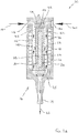
- an electronic vapour inhaler 10 comprises a generally elongate housing 12 having a proximal end 14 and a distal end 16.
- the electronic vapour inhaler 10 includes a mouthpiece 18 at the proximal end 14 through which a user can inhale vapour generated by heating a flavour-release medium 30.
- the electronic vapour inhaler 10 includes a control arrangement 20, e.g. in the form of a microprocessor, and a power source 22 in the form of one or more batteries which could, for example, be inductively rechargeable.
- the housing 12 includes a chamber 24 into which a cartridge 26 can be removably inserted.
- the chamber 24 is located at the proximal end 16 of the housing 12 adjacent to the mouthpiece 18, but this is not strictly necessary and it could be located at any suitable position between the proximal end 14 and the distal end 16.
- the chamber 24 is formed in the housing 12 and is accessed by removing a cover 25, with which the mouthpiece 18 is integrally formed, from the proximal end 14 of the housing 12.
- the chamber 24 could itself be formed as a removable component and could be accessed by removing the component from the housing 12. Either way, a cartridge 26 can be easily inserted into, or removed from, the chamber 24.
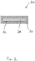
- the cartridge 26, which is shown separately in Figure 2 for clarity purposes, comprises an elongate induction heatable element 28 in the form of a rod which is typically, but not exclusively, circular in cross-section.
- the cartridge 26 further comprises a flavour-release medium 30 which is adhered, e.g. as a coating, to the surface 32 of the induction heatable element 28.
- the flavour-release medium 30 is a granulated or particulate material which may be treated or processed to enable it to adhere to the induction heatable element 28.
- the flavour-release medium 30 comprises tobacco or a tobacco material which may be impregnated with a vapour-forming medium, such as propylene glycol or glycerol, so that it can be heated to produce a vapour for inhalation by a user through the mouthpiece 18 of the electronic vapour inhaler 10.
- a vapour-forming medium such as propylene glycol or glycerol
- the induction heatable element 28 is in intimate contact with the flavour-release medium 30 due to the fact that the flavour-release medium 30 is adhered to it. As a result, when the induction heatable element 28 is heated in the presence of an electromagnetic field, the flavour-release medium 30 is heated rapidly and uniformly.
- the electronic vapour inhaler 10 includes an induction heating arrangement 34 comprising an induction coil 36 which can be energised by the power source 22.
- an induction coil 36 which can be energised by the power source 22.
- an electromagnetic field is produced which generates eddy currents in the induction heatable element 28 causing it to heat up.
- the heat is then transferred from the induction heatable element 28 to the flavour-release medium 30, for example by conduction, radiation and convection.
- the operation of the induction heating arrangement 34 is controlled by the control arrangement 20 typically in order to maintain the flavour-release medium 30 at a temperature which is optimised for the release of flavour and aroma therefrom.
- the electronic vapour inhaler 10 can include a temperature sensor to measure the temperature inside the chamber 24 and in this case the control arrangement 20 can be arranged to control the operation of the induction heating arrangement 34 based on the temperature measured by the temperature sensor.
- the control arrangement 20 can be arranged to control the operation of the induction heating arrangement 34 based on the temperature measured by the temperature sensor.
- Other arrangements for determining the temperature inside the chamber 24 are, however, possible as described earlier in this specification.
- the user may initially need to gain access to the chamber 24, for example by removing the cover 25 from the proximal end 14 of the housing 12 (e.g. by unscrewing it).
- the user then places a pre-manufactured cartridge 26 into the chamber 24.
- Pre-manufactured cartridges 26 are typically supplied in a pack which can be purchased separately. Loading the cartridge 26 into the chamber 24 is, therefore, a very simple procedure for the user.
- the electronic vapour inhaler 10 can then be switched on by the user ready for use, thereby energising the induction coil 36 and heating the induction heatable element 28 and the flavour-release medium 30 as described above such that the flavour-release medium 30 is heated without being combusted.
- the control arrangement 20 could include a temperature selector to allow a user to select the desired vapour inhalation temperature to select the desired user experience, since the optimum inhalation temperature may be a matter of personal choice.
- the induction coil 36 can be energised as necessary to maintain a predetermined, e.g. substantially constant, temperature inside the chamber 24. This in turn ensures that the temperature of the vapour inhaled by the user through the mouthpiece 18 is optimised, e.g. substantially constant.
- the control arrangement 20 can be arranged to control the induction heating arrangement 34 so that the induction coil 36 is energised in such a way that the temperature inside the chamber 24 decreases between inhalation cycles and increases immediately before, or at the start of, the next inhalation cycle.
- the chamber 24 can be accessed, for example by removing the cover 25 from the proximal end 14 of the housing 12.
- the used cartridge 26 can then be removed and discarded, and a new cartridge 26 can be placed in the chamber 24 before the cover 25 is replaced as described above to ready the electronic vapour inhaler 10 for use.
- the contents of the cartridge 26, and in particular the constituents of the flavour-release medium may vary and that the operation of the induction heating arrangement 34 may ideally need to be varied to optimise the release of flavour and aroma from the flavour-release medium.
- the contents of certain cartridges 26 may favour a heating profile with a relatively slow heating rate whereas the contents of other cartridges 26 may favour a heating profile with a relatively rapid heating rate.
- the control arrangement 20 is arranged to recognise an inserted cartridge 26 by detecting a characteristic of the induction heatable element 28 and to control the operation of the induction heating arrangement 34 to provide a desired heating profile, based on the detected characteristic.
- the control arrangement 20 detects a change in the electromagnetic field generated by the interaction between the induction heatable element 28 and the induction coil 36.
- different electromagnetic field signatures can be provided for different cartridges 26 by providing one or more induction heatable elements 28 of different length, thickness or shape.
- FIG 1a shows an alternative embodiment of part of an electronic vapour inhaler 110.
- the electronic vapour inhaler 110 shares many features in common with the electronic vapour inhaler 10 shown in Figure 1 and corresponding features are, therefore, designated with corresponding reference numerals.
- the electronic vapour inhaler 110 has an annular conduit 112 which surrounds the chamber 24.
- the annular conduit 112 is formed between a circumferential wall of the housing 12 in which the induction coil 36 is embedded and a circumferential wall 114 of the chamber 24.
- the annular conduit 112 includes a plurality of circumferentially spaced first inlets 116 formed in the housing 12 at the distal end of the annular conduit 112 to enable ambient air to flow into the annular conduit 112.
- the annular conduit 112 also includes a plurality of circumferentially spaced second inlets 118 which are formed in the circumferential wall 114 of the chamber 24 to enable heated air to flow from the chamber 24 into the annular conduit 112.
- the second inlets 118 are formed in the circumferential wall 114 roughly at the midpoint of the annular conduit 112, between the distal and proximal ends thereof, but other positions are of course entirely feasible and within the scope of the present disclosure.
- Circumferentially spaced passages 120, 122 are also provided in the housing 12 to direct a proportion of ambient air from the first inlets 116 along passage 124 and into the chamber 24.
- ambient air is drawn through the circumferentially spaced first inlets 116 into the annular conduit 112, as shown by the arrows 140.
- the ambient air flows along the annular conduit 112, from the distal end towards the proximal end, towards the mouthpiece 18 as shown by the arrows 142.
- a venturi effect occurs. This causes ambient air to be drawn through the passages 120, 122, 124 into the chamber 24 and to be sucked out of the chamber 24 through the second inlets 118, as shown by the dotted arrows.
- the air entering the chamber through the passages 120, 122, 124 is heated as it flows through the granulated or particulate flavour-release medium 30 in the chamber 24 and, accordingly, heated air with a suitable aroma and flavour is sucked out of the chamber 24 through the second inlets 118.
- the heated air mixes with the ambient air flowing through the annular conduit 112 and this tends to reduce the temperature of the heated air to a more acceptable level.
- the heated air then cools further and condenses to form a vapour or aerosol which can be inhaled by a user through the mouthpiece 18, as denoted by the arrow 42.
- a cartridge 44 comprising a tubular (possibly cylindrical) induction heatable element 46.
- the tubular induction heatable element 46 has a wall 48 with inner and outer wall surfaces 50, 52 and flavour-release medium 54 is adhered to both the inner and outer wall surfaces 50, 52.
- the flavour-release medium 54 could be adhered to just one of the inner and outer wall surfaces 50, 52.
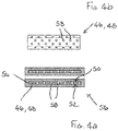
- Figures 4a and 4b show a cartridge 56 similar to the cartridge 44 of Figure 3 and in which corresponding components are identified using corresponding reference numerals.
- the tubular induction heatable element 46 (which is cylindrical in the illustrated embodiment) includes perforations 58 so that air can flow through the wall 48 between the inner and outer wall surfaces 50, 52.
- a cartridge 60 comprising an elongate induction heatable element 62 in the form of a rod which is typically, but not exclusively, circular in cross-section.
- the cartridge 60 further comprises a flavour-release medium 64 which surrounds the induction heatable element 62.
- a thermally-insulating, electrically-insulating and non-magnetic protective sleeve 66 surrounds the flavour-release medium 64 and may advantageously hold it in position, in particular if the flavour-release medium 64 comprises fine pieces or particles of material.
- the flavour-release medium 64 can comprise interwoven fibres and this may be sufficient to retain the fibrous flavour-release medium 64 in position around the induction heatable element 62 without a protective sleeve 66 being needed.
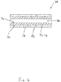
- FIG. 6 shows a cartridge 68 comprising a tubular (possibly cylindrical) induction heatable element 70.
- the tubular induction heatable element 70 comprises a wall 72 with inner and outer wall surfaces 74, 76 and flavour-release medium 78 is provided exclusively around the outer wall surface 76 to surround the induction heatable element 70.
- the interior 80 of the tubular induction heatable element 70 is devoid of flavour-release medium 78.
- a thermally-insulating, electrically-insulating and non-magnetic protective sleeve 82 surrounds the flavour-release medium 78 and may advantageously hold it in position, in particular if the flavour-release medium 78 comprises fine pieces or particles of material.
- the flavour-release medium 78 can comprise interwoven fibres and this may be sufficient to retain the fibrous flavour-release medium 78 in position around the induction heatable element 70 without a protective sleeve 82 being needed.
- the tubular induction heatable element 70 includes perforations so that air can flow through the wall 72 between the inner and outer wall surfaces 74, 76.
- a cartridge 84 comprising a flavour-release medium 86 in the form of fine pieces or pellets, particles, flakes or a fibrous form.
- a paper overwrap is provided to act as a protective sleeve 88 but, as described with respect to earlier embodiments, this may be omitted if, for example, the flavour-release medium 86 comprises interwoven fibres or the like which enable it to retain its shape in the absence of the support structure provided by the protective sleeve 88.
- the cartridge 84 further comprises an induction heatable material 90 in the form of particles of material which are individually inductively heated in the presence of an electromagnetic field.
- the particles of the induction heatable material 90 are dispersed throughout the flavour-release medium, typically but not exclusively in a uniform manner.
- either of the electronic vapour inhalers 10, 110 could be provided with an airflow control mechanism to enable a user to control the airflow through the inlets 38, 116.
- the airflow control mechanism could comprise means for varying the aperture size of the inlets 38, 116 to restrict the flow of air into the inlets 38, 116.
- flavour-release medium It may be desirable in any of the aforementioned embodiments to provide a thermally-insulating material between the induction heatable element and the flavour-release medium to reduce the rate of heat transfer to the flavour-release medium.
Landscapes
- Health & Medical Sciences (AREA)
- Engineering & Computer Science (AREA)
- Physics & Mathematics (AREA)
- Electromagnetism (AREA)
- Veterinary Medicine (AREA)
- Anesthesiology (AREA)
- Biomedical Technology (AREA)
- Heart & Thoracic Surgery (AREA)
- Hematology (AREA)
- Life Sciences & Earth Sciences (AREA)
- Animal Behavior & Ethology (AREA)
- General Health & Medical Sciences (AREA)
- Public Health (AREA)
- Pulmonology (AREA)
- Bioinformatics & Cheminformatics (AREA)
- General Chemical & Material Sciences (AREA)
- Chemical & Material Sciences (AREA)
- Chemical Kinetics & Catalysis (AREA)
- Thermotherapy And Cooling Therapy Devices (AREA)
- General Induction Heating (AREA)
- Vaporization, Distillation, Condensation, Sublimation, And Cold Traps (AREA)
- Disinfection, Sterilisation Or Deodorisation Of Air (AREA)
- Medicinal Preparation (AREA)
- Cigarettes, Filters, And Manufacturing Of Filters (AREA)
- Apparatus For Making Beverages (AREA)
- Magnetic Treatment Devices (AREA)
- Fats And Perfumes (AREA)
- Sampling And Sample Adjustment (AREA)
- Apparatus For Disinfection Or Sterilisation (AREA)
- Manufacture Of Tobacco Products (AREA)
- Respiratory Apparatuses And Protective Means (AREA)
Description
- The present disclosure relates generally to electronic vapour inhalers in which a flavour-release medium can be heated to produce a vapour for inhalation by a user.
- The use of electronic vapour inhalers (also known as electronic cigarettes, e-cigarettes and personal vaporisers), which can be used as an alternative to conventional smoking articles such as cigarettes, cigars, and pipes, is becoming increasingly popular and widespread. Electronic vapour inhalers, which are usually battery powered, heat and atomise a liquid containing nicotine, to produce a nicotine-containing vapour which can be inhaled by a user. The vapour is inhaled through a mouthpiece to deliver nicotine to the lungs, and vapour exhaled by the user generally mimics the appearance of smoke from a conventional smoking article. Although inhalation of the vapour creates a physical sensation which is similar to conventional smoking, harmful chemicals such as carbon monoxide and tar, are not produced or inhaled because there is no combustion.
- Various electronic vapour inhalers are currently available but they all have drawbacks associated with them which the present disclosure seeks to overcome.
- The preamble of
claim 1 is derivable fromWO 95/27411 A1 - According to a first aspect of the present disclosure, there is provided an electronic vapour inhaler comprising:
- a housing;
- a cartridge positioned in the housing, the cartridge comprising an induction heatable element and a flavour-release medium, wherein the flavour-release medium is tobacco or a tobacco material;
- an induction heating arrangement arranged to inductively heat the induction heatable element to heat the flavour-release medium within the cartridge; and
- a control arrangement which is arranged to energise the induction heating arrangement to inductively heat the induction heatable element and thereby heat the flavour-release medium;
- the control arrangement being further arranged to recognise the cartridge by detecting a characteristic of the induction heatable element and to control the operation of the induction heating arrangement based on the detected characteristic to provide one of a plurality of predetermined heating profiles adapted to optimally heat the cartridge.
- The induction heatable element is effectively 'read' as the cartridge is inserted into the housing thereby providing automatic recognition of the cartridge.
- The heating profile is set automatically upon recognition of the cartridge so that the flavour-release medium is heated in an optimum manner to release the flavour and aroma therefrom.
- The control arrangement may be adapted to detect a change in the electromagnetic field generated by the interaction between the induction heatable element and the induction heating arrangement during insertion of the cartridge into the housing.
- The characteristic to be detected, such as the change in the electromagnetic field, could be varied between different cartridges for example by providing induction heatable elements of differing length, thickness or shape.
- The cartridge may comprise:
- an elongate induction heatable element; and
- a flavour-release medium adhered to an outer surface of the elongate induction heatable element.
- The cartridge provides a convenient way for a user to load the flavour-release medium into the electronic vapour inhaler, thereby reducing the likelihood of spillage and waste. The integrity, safety and quality of the flavour-release medium can also be assured, because it is provided in the form of a pre-manufactured cartridge. Correct dosing of the flavour-release medium is also assured.
- By arranging the induction heatable element in close proximity to the flavour-release medium and in contact with at least some of it, the flavour-release medium is heated rapidly and efficiently in the presence of an electromagnetic field and this gives a fast heating response with a relatively low power requirement. The cartridge does not have any moving parts and the heating element is disposed along with the cartridge. The heating element does not wear out and is not subject to a build-up of residue formed by deposits from the heated flavour-release medium because it is renewed each time the cartridge is replaced and there is, therefore, no reduction in performance or degradation in flavour or aroma over time. This is to be contrasted, for example, with existing electronic vapour inhalers which have a resistance heating element in the housing of the inhaler which wears out or fails after a certain amount of use and which is subject to the build-up of residue as the flavour-release medium is heated. In the event of failure, the electronic vapour inhaler may need to be discarded entirely and replaced with a new one.
- When heated, the flavour-release medium releases a vapour for inhalation by a user. The flavour-release medium may be impregnated with a vapour-forming medium such as propylene glycol or glycerol.
- The flavour release medium may, for example, comprise a granulated material which may be adhered to the outer surface of the induction heatable element. The flavour-release medium can, therefore, be attached to the induction heatable element in a simple manner.
- The elongate induction heatable element may comprise a rod or a wire which may have a solid cross-section.
- The elongate induction heatable element may alternatively comprise a tube having a wall with an inner wall surface and an outer wall surface. The tube may, for example, be cylindrical or elliptical and the wall may be a circumferentially extending wall having an inner circumferential wall surface and an outer circumferential wall surface. The flavour release medium may be adhered to the inner wall surface and/or the outer wall surface. In arrangements where the flavour-release medium is adhered to both the inner and outer wall surfaces of the tubular induction heatable element, an increased amount of flavour and aroma may be released.
- The tubular induction heatable element may comprise one or more openings in the wall to allow air and gases to flow therethrough. For example, the tubular induction heatable element could comprise a tubular mesh or a tubular perforated foil.
- The cartridge may further comprise a thermally-insulating layer between the induction heatable element and the flavour-release medium. The thermally-insulating layer may usefully slow down the rate at which the flavour-release medium is heated.
- The cartridge may comprise:
- a tubular induction heatable element; and
- a flavour-release medium provided exclusively to surround the tubular induction heatable element whereby the interior of the tubular induction heatable element is devoid of said flavour-release medium.
- The tubular induction heatable element may comprise one or more openings in a wall thereof surrounded by the flavour-release medium to allow air and gases to flow through the wall. For example, the tubular induction heatable element could comprise a tubular mesh or a tubular perforated foil.
- The cartridge may include a protective sleeve surrounding the flavour-release medium.
- The protective sleeve may comprise a thermally-insulating material which may also be electrically-insulating and which may be non-magnetic. The protective sleeve could comprise a paper overwrap.
- The protective sleeve may be tubular and may have open ends. The protective sleeve could, for example, be circular or elliptical in cross-section.
- The tubular induction heatable element and the tubular protective sleeve may be concentric.
- The cartridge may further comprise a thermally-insulating layer between the induction heatable element and the flavour-release medium.
- The electronic vapour inhaler may include a mouthpiece at the proximal end of the housing. The housing may include a chamber in which the cartridge is removably disposed. The chamber may be thermally isolated from the external environment. The chamber could be located at any suitable position between the distal end and the proximal end of the housing. In some embodiments, the chamber could be located at the proximal end. In other embodiments, the chamber could be located at the distal end. In the latter case, even if there is a slight increase in temperature at the outer surface of the housing as the cartridge is heated during operation of the induction heating arrangement, this increase in temperature would not occur at the proximal end of the housing where the mouthpiece is located.
- The induction heating arrangement may comprise an induction coil. The induction coil may extend around the chamber.
- The housing may include an air inlet through which air can flow into the chamber. A plurality of air inlets could be provided.
- The housing may be fitted with an airflow control mechanism to vary the airflow through the or each air inlet and, hence, through the cartridge. This might allow a user to influence the amount of flavour and aroma released from the heated flavour-release medium during inhalation through the mouthpiece.
- The housing may include a conduit for delivering heated flavour-release medium to the mouthpiece. The conduit may include at least one first inlet for ambient air and at least one second inlet for heated air from the chamber. The conduit may be arranged to provide a venturi effect, so that the heated air is sucked into the conduit from the chamber by the venturi effect as ambient air flows through the conduit past the at least one second inlet. With such an arrangement, relatively cool ambient air and relatively hot air from the chamber are mixed together as they flow through the conduit and this may provide a more gradual release of flavour and aroma during inhalation through the mouthpiece. The housing may be fitted with an airflow control mechanism to vary the flow through the at least one first inlet. The conduit is typically an annular conduit which surrounds the chamber. The annular conduit may include a plurality of circumferentially spaced first inlets formed in the housing and a plurality of circumferentially spaced second inlets formed in a circumferential wall of the chamber.
- The electronic vapour inhaler may include one or more temperature sensors to determine the cartridge temperature. Any suitable temperature sensor could be used, for example a thermocouple, a resistance temperature detector, a thermistor or an infra-red sensor. In one implementation, the temperature sensor(s) may determine the cartridge temperature by direct measurement of the cartridge temperature. In another implementation, the temperature sensor(s) may be used to determine the cartridge temperature indirectly. For example, a temperature sensor could be used to measure the temperature of the airflow into the chamber through the or each air inlet and the cartridge temperature could then be determined mathematically as a function of the measured air inlet temperature, the properties of the cartridge and the amount of energy supplied by the induction heating arrangement.
-
-
Figure 1 is diagrammatic cross-sectional view of an electronic vapour including a cartridge according to aspects of the present disclosure having an elongate rod-like induction heatable element with flavour-release medium adhered to its outer surface; -
Figure 1a is a view similar toFigure 1 , showing part of an alternative embodiment of an electronic vapour inhaler; -
Figure 2 is a cross-sectional side view of the cartridge shown inFigures 1 and2 ; -
Figure 3 is a diagrammatic cross-sectional side view of a cartridge having a tubular induction heatable element with flavour-release medium adhered to inner and outer wall surfaces; -
Figure 4a is a view of a cartridge similar to the cartridge shown inFigure 3 but having a perforated tubular induction heatable element andFigure 4b is a side view of the perforated tubular induction heatable element; -
Figure 5 is a diagrammatic cross-sectional side view of a cartridge having an elongate rod-like induction heatable element with flavour-release medium surrounding it; -
Figure 6 is a diagrammatic cross-sectional side view of a cartridge having a tubular induction heatable element with flavour-release medium surrounding it; and -
Figure 7 is a diagrammatic cross-sectional side view of a cartridge in which particulate induction heatable material is dispersed throughout a flavour-release medium. - Embodiments of the present disclosure will now be described by way of example only and with reference to the accompanying drawings.
- Referring initially to
Figure 1 , anelectronic vapour inhaler 10 comprises a generallyelongate housing 12 having aproximal end 14 and adistal end 16. Theelectronic vapour inhaler 10 includes amouthpiece 18 at theproximal end 14 through which a user can inhale vapour generated by heating a flavour-release medium 30. Theelectronic vapour inhaler 10 includes acontrol arrangement 20, e.g. in the form of a microprocessor, and apower source 22 in the form of one or more batteries which could, for example, be inductively rechargeable. - The
housing 12 includes achamber 24 into which acartridge 26 can be removably inserted. Thechamber 24 is located at theproximal end 16 of thehousing 12 adjacent to themouthpiece 18, but this is not strictly necessary and it could be located at any suitable position between theproximal end 14 and thedistal end 16. In the illustrated embodiment, thechamber 24 is formed in thehousing 12 and is accessed by removing acover 25, with which themouthpiece 18 is integrally formed, from theproximal end 14 of thehousing 12. In alternative embodiments, thechamber 24 could itself be formed as a removable component and could be accessed by removing the component from thehousing 12. Either way, acartridge 26 can be easily inserted into, or removed from, thechamber 24. - The
cartridge 26, which is shown separately inFigure 2 for clarity purposes, comprises an elongate inductionheatable element 28 in the form of a rod which is typically, but not exclusively, circular in cross-section. Thecartridge 26 further comprises a flavour-release medium 30 which is adhered, e.g. as a coating, to thesurface 32 of the inductionheatable element 28. The flavour-release medium 30 is a granulated or particulate material which may be treated or processed to enable it to adhere to the inductionheatable element 28. The flavour-release medium 30 comprises tobacco or a tobacco material which may be impregnated with a vapour-forming medium, such as propylene glycol or glycerol, so that it can be heated to produce a vapour for inhalation by a user through themouthpiece 18 of theelectronic vapour inhaler 10. When tobacco or a tobacco material is used, theelectronic vapour inhaler 10 can be used as an electronic cigarette. - The induction
heatable element 28 is in intimate contact with the flavour-release medium 30 due to the fact that the flavour-release medium 30 is adhered to it. As a result, when the inductionheatable element 28 is heated in the presence of an electromagnetic field, the flavour-release medium 30 is heated rapidly and uniformly. - Referring again to
Figure 1 , theelectronic vapour inhaler 10 includes aninduction heating arrangement 34 comprising aninduction coil 36 which can be energised by thepower source 22. As will be understood by those skilled in the art, when theinduction coil 36 is energised, an electromagnetic field is produced which generates eddy currents in the inductionheatable element 28 causing it to heat up. The heat is then transferred from the inductionheatable element 28 to the flavour-release medium 30, for example by conduction, radiation and convection. - The operation of the
induction heating arrangement 34 is controlled by thecontrol arrangement 20 typically in order to maintain the flavour-release medium 30 at a temperature which is optimised for the release of flavour and aroma therefrom. - Although not shown in
Figure 1 , theelectronic vapour inhaler 10 can include a temperature sensor to measure the temperature inside thechamber 24 and in this case thecontrol arrangement 20 can be arranged to control the operation of theinduction heating arrangement 34 based on the temperature measured by the temperature sensor. Other arrangements for determining the temperature inside thechamber 24 are, however, possible as described earlier in this specification. - When a user wishes to use the
electronic vapour inhaler 10 to inhale vapour, the user may initially need to gain access to thechamber 24, for example by removing thecover 25 from theproximal end 14 of the housing 12 (e.g. by unscrewing it). The user then places apre-manufactured cartridge 26 into thechamber 24.Pre-manufactured cartridges 26 are typically supplied in a pack which can be purchased separately. Loading thecartridge 26 into thechamber 24 is, therefore, a very simple procedure for the user. - The user then closes the
chamber 24, for example by re-attaching thecover 25 to theproximal end 14 of the housing 12 (e.g. by screwing it back on to the housing 12). Theelectronic vapour inhaler 10 can then be switched on by the user ready for use, thereby energising theinduction coil 36 and heating the inductionheatable element 28 and the flavour-release medium 30 as described above such that the flavour-release medium 30 is heated without being combusted. - When a user places their mouth over the
mouthpiece 18 and inhales, ambient air is drawn throughair inlets 38 into thechamber 24, as denoted by thearrows 40. The air is heated as it flows through the granulated or particulate flavour-release medium 30 in thechamber 24 and heated air with a suitable aroma and flavour flows out of thechamber 24. The heated air then flows through themouthpiece 18 and, in doing so, it cools and condenses to form a vapour or aerosol which can be inhaled by a user through themouthpiece 18, as denoted by thearrow 42. Thecontrol arrangement 20 could include a temperature selector to allow a user to select the desired vapour inhalation temperature to select the desired user experience, since the optimum inhalation temperature may be a matter of personal choice. - During inhalation, and as air flows into and through the
chamber 24, it will be understood that theinduction coil 36 can be energised as necessary to maintain a predetermined, e.g. substantially constant, temperature inside thechamber 24. This in turn ensures that the temperature of the vapour inhaled by the user through themouthpiece 18 is optimised, e.g. substantially constant. However, in order to preserve the flavour-release medium 30, thecontrol arrangement 20 can be arranged to control theinduction heating arrangement 34 so that theinduction coil 36 is energised in such a way that the temperature inside thechamber 24 decreases between inhalation cycles and increases immediately before, or at the start of, the next inhalation cycle. - When the flavour and aroma of the vapour supplied to the
mouthpiece 18 has reached a level which is considered by a user to be unacceptable, thechamber 24 can be accessed, for example by removing thecover 25 from theproximal end 14 of thehousing 12. The usedcartridge 26 can then be removed and discarded, and anew cartridge 26 can be placed in thechamber 24 before thecover 25 is replaced as described above to ready theelectronic vapour inhaler 10 for use. - It will be appreciated that the contents of the
cartridge 26, and in particular the constituents of the flavour-release medium, may vary and that the operation of theinduction heating arrangement 34 may ideally need to be varied to optimise the release of flavour and aroma from the flavour-release medium. For example, the contents ofcertain cartridges 26 may favour a heating profile with a relatively slow heating rate whereas the contents ofother cartridges 26 may favour a heating profile with a relatively rapid heating rate. In order to accommodate this, in one embodiment thecontrol arrangement 20 is arranged to recognise an insertedcartridge 26 by detecting a characteristic of the inductionheatable element 28 and to control the operation of theinduction heating arrangement 34 to provide a desired heating profile, based on the detected characteristic. In one possible implementation, as acartridge 26 is inserted into thechamber 24, thecontrol arrangement 20 detects a change in the electromagnetic field generated by the interaction between the inductionheatable element 28 and theinduction coil 36. In practice, different electromagnetic field signatures can be provided fordifferent cartridges 26 by providing one or more inductionheatable elements 28 of different length, thickness or shape. -
Figure 1a shows an alternative embodiment of part of anelectronic vapour inhaler 110. Theelectronic vapour inhaler 110 shares many features in common with theelectronic vapour inhaler 10 shown inFigure 1 and corresponding features are, therefore, designated with corresponding reference numerals. - The
electronic vapour inhaler 110 has an annular conduit 112 which surrounds thechamber 24. The annular conduit 112 is formed between a circumferential wall of thehousing 12 in which theinduction coil 36 is embedded and a circumferential wall 114 of thechamber 24. The annular conduit 112 includes a plurality of circumferentially spaced first inlets 116 formed in thehousing 12 at the distal end of the annular conduit 112 to enable ambient air to flow into the annular conduit 112. The annular conduit 112 also includes a plurality of circumferentially spacedsecond inlets 118 which are formed in the circumferential wall 114 of thechamber 24 to enable heated air to flow from thechamber 24 into the annular conduit 112. Thesecond inlets 118 are formed in the circumferential wall 114 roughly at the midpoint of the annular conduit 112, between the distal and proximal ends thereof, but other positions are of course entirely feasible and within the scope of the present disclosure. Circumferentially spacedpassages housing 12 to direct a proportion of ambient air from the first inlets 116 alongpassage 124 and into thechamber 24. - During inhalation through the
mouthpiece 18, ambient air is drawn through the circumferentially spaced first inlets 116 into the annular conduit 112, as shown by thearrows 140. The ambient air flows along the annular conduit 112, from the distal end towards the proximal end, towards themouthpiece 18 as shown by thearrows 142. As the air flows past the circumferentially spacedsecond inlets 118 in the chamber wall 114, a venturi effect occurs. This causes ambient air to be drawn through thepassages chamber 24 and to be sucked out of thechamber 24 through thesecond inlets 118, as shown by the dotted arrows. As will be understood, the air entering the chamber through thepassages release medium 30 in thechamber 24 and, accordingly, heated air with a suitable aroma and flavour is sucked out of thechamber 24 through thesecond inlets 118. The heated air mixes with the ambient air flowing through the annular conduit 112 and this tends to reduce the temperature of the heated air to a more acceptable level. The heated air then cools further and condenses to form a vapour or aerosol which can be inhaled by a user through themouthpiece 18, as denoted by thearrow 42. - Alternative cartridges can be used with the
electronic vapour inhalers - Referring to
Figure 3 , there is shown acartridge 44 comprising a tubular (possibly cylindrical) induction heatable element 46. The tubular induction heatable element 46 has a wall 48 with inner and outer wall surfaces 50, 52 and flavour-release medium 54 is adhered to both the inner and outer wall surfaces 50, 52. In other embodiments, the flavour-release medium 54 could be adhered to just one of the inner and outer wall surfaces 50, 52. -
Figures 4a and 4b show acartridge 56 similar to thecartridge 44 ofFigure 3 and in which corresponding components are identified using corresponding reference numerals. In thecartridge 56 ofFigures 4a and 4b , the tubular induction heatable element 46 (which is cylindrical in the illustrated embodiment) includesperforations 58 so that air can flow through the wall 48 between the inner and outer wall surfaces 50, 52. - Referring now to
Figure 5 , there is shown acartridge 60 comprising an elongate inductionheatable element 62 in the form of a rod which is typically, but not exclusively, circular in cross-section. Thecartridge 60 further comprises a flavour-release medium 64 which surrounds the inductionheatable element 62. A thermally-insulating, electrically-insulating and non-magnetic protective sleeve 66, for example in the form of a paper overwrap having open ends, surrounds the flavour-release medium 64 and may advantageously hold it in position, in particular if the flavour-release medium 64 comprises fine pieces or particles of material. In other embodiments, the flavour-release medium 64 can comprise interwoven fibres and this may be sufficient to retain the fibrous flavour-release medium 64 in position around the inductionheatable element 62 without a protective sleeve 66 being needed. -
Figure 6 shows acartridge 68 comprising a tubular (possibly cylindrical) induction heatable element 70. The tubular induction heatable element 70 comprises a wall 72 with inner and outer wall surfaces 74, 76 and flavour-release medium 78 is provided exclusively around the outer wall surface 76 to surround the induction heatable element 70. Thus, theinterior 80 of the tubular induction heatable element 70 is devoid of flavour-release medium 78. - A thermally-insulating, electrically-insulating and non-magnetic
protective sleeve 82, for example in the form of a paper overwrap, surrounds the flavour-release medium 78 and may advantageously hold it in position, in particular if the flavour-release medium 78 comprises fine pieces or particles of material. In other embodiments, the flavour-release medium 78 can comprise interwoven fibres and this may be sufficient to retain the fibrous flavour-release medium 78 in position around the induction heatable element 70 without aprotective sleeve 82 being needed. - In a modified implementation of the cartridge 68 (not illustrated), the tubular induction heatable element 70 includes perforations so that air can flow through the wall 72 between the inner and outer wall surfaces 74, 76.
- Referring now to
Figure 7 , there is shown acartridge 84 comprising a flavour-release medium 86 in the form of fine pieces or pellets, particles, flakes or a fibrous form. In the illustrated embodiment, a paper overwrap is provided to act as aprotective sleeve 88 but, as described with respect to earlier embodiments, this may be omitted if, for example, the flavour-release medium 86 comprises interwoven fibres or the like which enable it to retain its shape in the absence of the support structure provided by theprotective sleeve 88. - The
cartridge 84 further comprises aninduction heatable material 90 in the form of particles of material which are individually inductively heated in the presence of an electromagnetic field. The particles of theinduction heatable material 90 are dispersed throughout the flavour-release medium, typically but not exclusively in a uniform manner. - Although exemplary embodiments have been described in the preceding paragraphs, it should be understood that various modifications may be made to those embodiments without departing from the scope of the appended claims. Thus, the breadth and scope of the claims should not be limited to the above-described exemplary embodiments. Each feature disclosed in the specification, including the claims and drawings, may be replaced by alternative features serving the same, equivalent or similar purposes, unless expressly stated otherwise.
- Although not illustrated, either of the
electronic vapour inhalers inlets 38, 116. For example, the airflow control mechanism could comprise means for varying the aperture size of theinlets 38, 116 to restrict the flow of air into theinlets 38, 116. - It may be desirable in any of the aforementioned embodiments to provide a thermally-insulating material between the induction heatable element and the flavour-release medium to reduce the rate of heat transfer to the flavour-release medium.
- Unless the context clearly requires otherwise, throughout the description and the claims, the words "comprise", "comprising", and the like, are to be construed in an inclusive as opposed to an exclusive or exhaustive sense; that is to say, in the sense of "including, but not limited to".
- Any combination of the above-described features in all possible variations thereof is encompassed by the present invention unless otherwise indicated herein or otherwise clearly contradicted by context.
Claims (14)
- An electronic vapour inhaler (10, 110) comprising:a housing (12);a cartridge (26, 44, 56, 60, 68, 84) positioned in the housing, the cartridge comprising an induction heatable element (28, 46, 62, 70, 90) and a flavour-release medium (30, 54, 64, 78, 86), wherein the flavour-release medium is tobacco or a tobacco material;an induction heating arrangement (34) arranged to inductively heat the induction heatable element (28, 46, 62, 70, 90) to heat the flavour-release medium (30, 54, 64, 78, 86) within the cartridge; anda control arrangement (20) which is arranged to energise the induction heating arrangement (34) to inductively heat the induction heatable element and thereby heat the flavour-release medium;characterized in that the control arrangement (20) is further arranged to recognise the cartridge by detecting a characteristic of the induction heatable element and to control the operation of the induction heating arrangement (34) based on the detected characteristic to provide one of a plurality of predetermined heating profiles adapted to optimally heat the cartridge.
- An electronic vapour inhaler according to claim 1, wherein the control arrangement (20) is arranged to detect a change in the electromagnetic field generated by the interaction between the induction heatable element (28, 46, 62, 70, 90) and the induction heating arrangement (34) during insertion of the cartridge into the housing (12).
- An electronic vapour inhaler according to claim 1 or claim 2, wherein:the induction heatable element is an elongate induction heatable element (28); andthe flavour-release medium (30) is adhered to an outer surface (32) of the elongate induction heatable element (28).
- An electronic vapour inhaler according to claim 3, wherein the elongate induction heatable element (28) comprises a rod or a wire having a solid cross-section.
- An electronic vapour inhaler according to claim 1 or claim 2, wherein:the induction heatable element is an elongate induction heatable element (46) comprising a tube having a wall (48) with inner and outer wall surfaces (50, 52); andthe flavour-release medium (54) is adhered to either one or both of the inner wall surface (50) and the outer wall surface (52).
- An electronic vapour inhaler according to claim 5, wherein the tubular induction heatable element (46) comprises one or more openings (58) in the wall (48) to allow air to flow therethrough.
- An electronic vapour inhaler according to any of claims 3 to 6, wherein the cartridge (26, 44, 56) further comprises a thermally-insulating layer between the induction heatable element (28, 46) and the flavour-release medium (30, 54).
- An electronic vapour inhaler according to claim 1 or claim 2, wherein:the induction heatable element is a tubular induction heatable element (70); andthe flavour-release medium (78) is provided exclusively to surround the tubular induction heatable element (70) whereby the interior (80) of the tubular induction heatable element (70) is devoid of said flavour-release medium (78).
- An electronic vapour inhaler according to claim 8, wherein the tubular induction heatable element (70) comprises one or more openings in a wall (72) thereof surrounded by the flavour-release medium (78) to allow air to flow through the wall (72).
- An electronic vapour inhaler according to claim 8 or claim 9, wherein the cartridge comprises a protective sleeve (82) surrounding the flavour-release medium (78).
- An electronic vapour inhaler according to claim 10, wherein the protective sleeve (82) comprises a thermally-insulating material which is also electrically-insulating and non-magnetic.
- An electronic vapour inhaler according to claim 10 or claim 11, wherein the protective sleeve (82) is tubular and has open ends.
- An electronic vapour inhaler according to claim 12, wherein the tubular induction heatable element (70) and the tubular protective sleeve (82) are concentric.
- An electronic vapour inhaler according to any of claims 8 to 13, wherein the cartridge (68) further comprises a thermally-insulating layer between the induction heatable element (70) and the flavour-release medium (78).
Priority Applications (3)
| Application Number | Priority Date | Filing Date | Title |
|---|---|---|---|
| RS20210301A RS61550B1 (en) | 2014-11-11 | 2015-11-03 | Electronic vapour inhalers |
| EP20205553.9A EP3795000B1 (en) | 2014-11-11 | 2015-11-03 | Electronic vapour inhalers |
| PL17170076T PL3245886T3 (en) | 2014-11-11 | 2015-11-03 | Electronic vapour inhalers |
Applications Claiming Priority (3)
| Application Number | Priority Date | Filing Date | Title |
|---|---|---|---|
| GB1420045.5A GB2533080B (en) | 2014-11-11 | 2014-11-11 | Electronic vapour inhalers |
| PCT/GB2015/053305 WO2016075436A1 (en) | 2014-11-11 | 2015-11-03 | Electronic vapour inhalers |
| EP15798169.7A EP3217817B1 (en) | 2014-11-11 | 2015-11-03 | Electronic vapour inhalers |
Related Parent Applications (2)
| Application Number | Title | Priority Date | Filing Date |
|---|---|---|---|
| EP15798169.7A Division EP3217817B1 (en) | 2014-11-11 | 2015-11-03 | Electronic vapour inhalers |
| EP15798169.7A Division-Into EP3217817B1 (en) | 2014-11-11 | 2015-11-03 | Electronic vapour inhalers |
Related Child Applications (2)
| Application Number | Title | Priority Date | Filing Date |
|---|---|---|---|
| EP20205553.9A Division EP3795000B1 (en) | 2014-11-11 | 2015-11-03 | Electronic vapour inhalers |
| EP20205553.9A Division-Into EP3795000B1 (en) | 2014-11-11 | 2015-11-03 | Electronic vapour inhalers |
Publications (2)
| Publication Number | Publication Date |
|---|---|
| EP3245886A1 EP3245886A1 (en) | 2017-11-22 |
| EP3245886B1 true EP3245886B1 (en) | 2020-12-30 |
Family
ID=52118314
Family Applications (5)
| Application Number | Title | Priority Date | Filing Date |
|---|---|---|---|
| EP15798169.7A Active EP3217817B1 (en) | 2014-11-11 | 2015-11-03 | Electronic vapour inhalers |
| EP20205553.9A Active EP3795000B1 (en) | 2014-11-11 | 2015-11-03 | Electronic vapour inhalers |
| EP17170076.8A Revoked EP3245886B1 (en) | 2014-11-11 | 2015-11-03 | Electronic vapour inhalers |
| EP20189136.3A Pending EP3753424A1 (en) | 2014-11-11 | 2015-11-03 | Electronic vapour inhalers |
| EP17170100.6A Active EP3248481B2 (en) | 2014-11-11 | 2015-11-03 | Electronic cigarette |
Family Applications Before (2)
| Application Number | Title | Priority Date | Filing Date |
|---|---|---|---|
| EP15798169.7A Active EP3217817B1 (en) | 2014-11-11 | 2015-11-03 | Electronic vapour inhalers |
| EP20205553.9A Active EP3795000B1 (en) | 2014-11-11 | 2015-11-03 | Electronic vapour inhalers |
Family Applications After (2)
| Application Number | Title | Priority Date | Filing Date |
|---|---|---|---|
| EP20189136.3A Pending EP3753424A1 (en) | 2014-11-11 | 2015-11-03 | Electronic vapour inhalers |
| EP17170100.6A Active EP3248481B2 (en) | 2014-11-11 | 2015-11-03 | Electronic cigarette |
Country Status (23)
| Country | Link |
|---|---|
| US (5) | US10856575B2 (en) |
| EP (5) | EP3217817B1 (en) |
| JP (10) | JP6779893B2 (en) |
| KR (3) | KR102560739B1 (en) |
| CN (2) | CN112385903B (en) |
| AU (3) | AU2015344854B2 (en) |
| BR (1) | BR112017009932A2 (en) |
| CA (2) | CA2967177A1 (en) |
| EA (3) | EA037950B1 (en) |
| ES (4) | ES2985702T3 (en) |
| GB (3) | GB2546934B (en) |
| HU (1) | HUE067649T2 (en) |
| MX (1) | MX2017006131A (en) |
| MY (1) | MY183452A (en) |
| NZ (2) | NZ732315A (en) |
| PH (1) | PH12017500850B1 (en) |
| PL (3) | PL3245886T3 (en) |
| PT (1) | PT3245886T (en) |
| RS (1) | RS61550B1 (en) |
| TR (1) | TR201910532T4 (en) |
| UA (2) | UA123085C2 (en) |
| WO (1) | WO2016075436A1 (en) |
| ZA (2) | ZA201703407B (en) |
Families Citing this family (167)
| Publication number | Priority date | Publication date | Assignee | Title |
|---|---|---|---|---|
| US10244793B2 (en) | 2005-07-19 | 2019-04-02 | Juul Labs, Inc. | Devices for vaporization of a substance |
| US11247003B2 (en) | 2010-08-23 | 2022-02-15 | Darren Rubin | Systems and methods of aerosol delivery with airflow regulation |
| WO2013034459A1 (en) | 2011-09-06 | 2013-03-14 | British American Tobacco (Investments) Limited | Heating smokeable material |
| GB201217067D0 (en) | 2012-09-25 | 2012-11-07 | British American Tobacco Co | Heating smokable material |
| US10279934B2 (en) | 2013-03-15 | 2019-05-07 | Juul Labs, Inc. | Fillable vaporizer cartridge and method of filling |
| US10039321B2 (en) | 2013-11-12 | 2018-08-07 | Vmr Products Llc | Vaporizer |
| US20160366947A1 (en) | 2013-12-23 | 2016-12-22 | James Monsees | Vaporizer apparatus |
| US10058129B2 (en) | 2013-12-23 | 2018-08-28 | Juul Labs, Inc. | Vaporization device systems and methods |
| US10076139B2 (en) | 2013-12-23 | 2018-09-18 | Juul Labs, Inc. | Vaporizer apparatus |
| USD842536S1 (en) | 2016-07-28 | 2019-03-05 | Juul Labs, Inc. | Vaporizer cartridge |
| KR102721939B1 (en) | 2013-12-23 | 2024-10-25 | 쥴 랩스, 인크. | Vaporization device systems and methods |
| USD825102S1 (en) | 2016-07-28 | 2018-08-07 | Juul Labs, Inc. | Vaporizer device with cartridge |
| US10159282B2 (en) | 2013-12-23 | 2018-12-25 | Juul Labs, Inc. | Cartridge for use with a vaporizer device |
| GB2527597B (en) * | 2014-06-27 | 2016-11-23 | Relco Induction Dev Ltd | Electronic Vapour Inhalers |
| KR20250012730A (en) | 2014-12-05 | 2025-01-24 | 쥴 랩스, 인크. | Calibrated dose control |
| GB201501429D0 (en) | 2015-01-28 | 2015-03-11 | British American Tobacco Co | Apparatus for heating aerosol generating material |
| WO2016184824A1 (en) | 2015-05-19 | 2016-11-24 | Jt International Sa | An aerosol generating device and capsule |
| GB201511349D0 (en) | 2015-06-29 | 2015-08-12 | Nicoventures Holdings Ltd | Electronic aerosol provision systems |
| GB201511359D0 (en) | 2015-06-29 | 2015-08-12 | Nicoventures Holdings Ltd | Electronic vapour provision system |
| GB201511361D0 (en) | 2015-06-29 | 2015-08-12 | Nicoventures Holdings Ltd | Electronic vapour provision system |
| PL3337344T3 (en) * | 2015-08-17 | 2019-12-31 | Philip Morris Products S.A. | Aerosol-generating system and aerosol-generating article for use in such a system |
| US20170055580A1 (en) * | 2015-08-31 | 2017-03-02 | British American Tobacco (Investments) Limited | Apparatus for heating smokable material |
| US20170055574A1 (en) | 2015-08-31 | 2017-03-02 | British American Tobacco (Investments) Limited | Cartridge for use with apparatus for heating smokable material |
| US20170055584A1 (en) | 2015-08-31 | 2017-03-02 | British American Tobacco (Investments) Limited | Article for use with apparatus for heating smokable material |
| US11924930B2 (en) | 2015-08-31 | 2024-03-05 | Nicoventures Trading Limited | Article for use with apparatus for heating smokable material |
| GB2543329B (en) * | 2015-10-15 | 2018-06-06 | Jt Int Sa | A method for operating an electronic vapour inhaler |
| US10582726B2 (en) | 2015-10-21 | 2020-03-10 | Rai Strategic Holdings, Inc. | Induction charging for an aerosol delivery device |
| WO2017068094A1 (en) * | 2015-10-22 | 2017-04-27 | Philip Morris Products S.A. | Aerosol-generating article, aerosol-generating system and method for manufacturing an aerosol-generating article |
| US20170119051A1 (en) | 2015-10-30 | 2017-05-04 | British American Tobacco (Investments) Limited | Article for Use with Apparatus for Heating Smokable Material |
| US20180317554A1 (en) | 2015-10-30 | 2018-11-08 | British American Tobacco (Investments) Limited | Article for use with apparatus for heating smokable material |
| US20170119046A1 (en) | 2015-10-30 | 2017-05-04 | British American Tobacco (Investments) Limited | Apparatus for Heating Smokable Material |
| US20170119049A1 (en) | 2015-10-30 | 2017-05-04 | British American Tobacco (Investments) Limited | Article for Use with Apparatus for Heating Smokable Material |
| US20170119050A1 (en) | 2015-10-30 | 2017-05-04 | British American Tobacco (Investments) Limited | Article for Use with Apparatus for Heating Smokable Material |
| US10820630B2 (en) | 2015-11-06 | 2020-11-03 | Rai Strategic Holdings, Inc. | Aerosol delivery device including a wirelessly-heated atomizer and related method |
| WO2017084489A1 (en) * | 2015-11-18 | 2017-05-26 | 常州聚为智能科技有限公司 | Cigarette holder, atomizer provided with cigarette holder, and electronic cigarette comprising atomizer |
| US10104912B2 (en) | 2016-01-20 | 2018-10-23 | Rai Strategic Holdings, Inc. | Control for an induction-based aerosol delivery device |
| MX377347B (en) | 2016-02-11 | 2025-03-07 | Juul Labs Inc | Fillable vaporizer cartridge and method of filling |
| MX388616B (en) | 2016-02-11 | 2025-03-20 | Juul Labs Inc | SECURE FITTING CARTRIDGES FOR VAPORIZING DEVICES |
| US10405582B2 (en) | 2016-03-10 | 2019-09-10 | Pax Labs, Inc. | Vaporization device with lip sensing |
| EP3445186B1 (en) * | 2016-04-20 | 2023-04-05 | Philip Morris Products S.A. | Hybrid aerosol-generating element and method for manufacturing a hybrid aerosol-generating element |
| CN105852218A (en) * | 2016-05-26 | 2016-08-17 | 湖南中烟工业有限责任公司 | Disposable cigarette cartridge and heating non-combustion cigarette utilizing multiple disposable cigarette cartridges |
| CN105768240A (en) * | 2016-05-26 | 2016-07-20 | 湖南中烟工业有限责任公司 | Disposable cartridge and electronic cigarette with same |
| CN105852219A (en) * | 2016-05-26 | 2016-08-17 | 湖南中烟工业有限责任公司 | Heating unfired cigarette capable of carrying out sectional type heating on disposable smoke cartridge |
| CN105831815A (en) * | 2016-05-26 | 2016-08-10 | 湖南中烟工业有限责任公司 | Disposable smoke cartridge and heating non-combustion cigarette comprising same |
| EP3471803B1 (en) | 2016-06-16 | 2022-08-10 | Juul Labs, Inc. | On-demand, portable convection vaporizer |
| USD849996S1 (en) | 2016-06-16 | 2019-05-28 | Pax Labs, Inc. | Vaporizer cartridge |
| USD836541S1 (en) | 2016-06-23 | 2018-12-25 | Pax Labs, Inc. | Charging device |
| USD851830S1 (en) | 2016-06-23 | 2019-06-18 | Pax Labs, Inc. | Combined vaporizer tamp and pick tool |
| JP6930804B2 (en) * | 2016-06-29 | 2021-09-01 | ニコベンチャーズ トレーディング リミテッド | Goods for use with equipment for heating smoking materials |
| EP3478104B1 (en) * | 2016-06-29 | 2023-03-22 | Nicoventures Trading Limited | Apparatus for heating smokable material |
| KR102468749B1 (en) | 2016-06-29 | 2022-11-17 | 니코벤처스 트레이딩 리미티드 | Apparatus for heating smokable material |
| US12478096B2 (en) | 2016-06-29 | 2025-11-25 | Nicoventures Trading Limited | Apparatus for heating smokable material |
| CN106037011B (en) * | 2016-07-13 | 2019-08-02 | 卓尔悦欧洲控股有限公司 | Atomising head, atomizer and electronic cigarette |
| CN206227716U (en) * | 2016-09-14 | 2017-06-09 | 深圳市合元科技有限公司 | The atomizer and electronic cigarette of electronic cigarette |
| CN109803549B (en) * | 2016-10-12 | 2022-03-01 | 日本烟草产业株式会社 | scented inhaler |
| CN206491335U (en) | 2016-10-28 | 2017-09-15 | 深圳市余看智能科技有限公司 | A kind of electronic smoke absorber |
| US10524508B2 (en) | 2016-11-15 | 2020-01-07 | Rai Strategic Holdings, Inc. | Induction-based aerosol delivery device |
| GB201700812D0 (en) * | 2017-01-17 | 2017-03-01 | British American Tobacco Investments Ltd | Apparatus for heating smokable material |
| USD891608S1 (en) * | 2017-01-31 | 2020-07-28 | Philip Morris Products S.A. | Dry powder inhaler |
| USD891609S1 (en) * | 2017-01-31 | 2020-07-28 | Philip Morris Products S.A. | Dry powder inhaler |
| KR20180124739A (en) | 2017-05-11 | 2018-11-21 | 주식회사 케이티앤지 | An aerosol generating device for controlling the temperature of a heater according to the type of cigarette and method thereof |
| GB201709201D0 (en) * | 2017-06-09 | 2017-07-26 | Nicoventures Holdings Ltd | Electronic aerosol provision system |
| WO2019003122A1 (en) * | 2017-06-27 | 2019-01-03 | Resolve Digital Health Inc. | A piercing device with perforator, heating mechanism and air passages |
| WO2019030301A1 (en) | 2017-08-09 | 2019-02-14 | Philip Morris Products S.A. | Aerosol generating system with non-circular inductor coil |
| WO2019030364A1 (en) * | 2017-08-09 | 2019-02-14 | Philip Morris Products S.A. | Aerosol-generating device having an elastic susceptor |
| JP7271505B2 (en) | 2017-08-09 | 2023-05-11 | フィリップ・モーリス・プロダクツ・ソシエテ・アノニム | Aerosol generator with removable susceptor |
| KR102551450B1 (en) | 2017-08-09 | 2023-07-06 | 필립모리스 프로덕츠 에스.에이. | Aerosol generating device with susceptor layer |
| EP3664642B1 (en) | 2017-08-09 | 2022-01-05 | Philip Morris Products S.A. | Aerosol-generating device having an inductor coil with reduced separation |
| US11793239B2 (en) | 2017-08-09 | 2023-10-24 | Philip Morris Products S.A. | Aerosol generating system with multiple susceptors |
| EP3664643B1 (en) | 2017-08-09 | 2021-09-29 | Philip Morris Products S.A. | Aerosol-generating device with flat inductor coil |
| HUE055702T2 (en) | 2017-08-09 | 2021-12-28 | Philip Morris Products Sa | Aerosol generation system with multiple induction coils |
| EP3679765B1 (en) * | 2017-09-06 | 2021-07-21 | JT International SA | Induction heating assembly for a vapour generating device |
| USD887632S1 (en) | 2017-09-14 | 2020-06-16 | Pax Labs, Inc. | Vaporizer cartridge |
| CA3075657C (en) | 2017-09-15 | 2023-10-10 | British American Tobacco (Investments) Limited | Apparatus for heating smokable material |
| GB201716735D0 (en) | 2017-10-12 | 2017-11-29 | British American Tobacco Investments Ltd | Aerosol provision systems |
| WO2019071575A1 (en) * | 2017-10-13 | 2019-04-18 | 惠州市吉瑞科技有限公司深圳分公司 | Atomization assembly and atomization system |
| GB201718923D0 (en) | 2017-11-16 | 2018-01-03 | British American Tobacco Investments Ltd | Consumable ventilation control |
| WO2019100230A1 (en) * | 2017-11-22 | 2019-05-31 | 惠州市吉瑞科技有限公司深圳分公司 | Atomization assembly and electronic cigarette |
| US20200288543A1 (en) * | 2017-11-30 | 2020-09-10 | Dynavap, LLC | Portable induction heater |
| GB201722183D0 (en) | 2017-12-28 | 2018-02-14 | British American Tobacco Investments Ltd | Apparatus for heating aerosolisable material |
| GB201722177D0 (en) | 2017-12-28 | 2018-02-14 | British American Tobacco Investments Ltd | Heating element |
| PL3731668T3 (en) * | 2017-12-28 | 2023-08-28 | Jt International Sa | Induction heating assembly for a vapour generating device |
| WO2019129846A1 (en) * | 2017-12-29 | 2019-07-04 | Jt International Sa | Induction heating assembly for a vapour generating device |
| TWI823887B (en) * | 2017-12-29 | 2023-12-01 | 瑞士商傑太日煙國際股份有限公司 | Induction heating assembly for a vapour generating device |
| TWI769355B (en) | 2017-12-29 | 2022-07-01 | 瑞士商傑太日煙國際股份有限公司 | Induction heating assembly for a vapour generating device |
| WO2019129843A1 (en) * | 2017-12-29 | 2019-07-04 | Jt International Sa | Heating assembly for a vapour generating device |
| TWI865437B (en) * | 2017-12-29 | 2024-12-11 | 瑞士商Jt國際公司 | Heating assembly for a vapour generating device |
| US12201154B2 (en) | 2018-01-03 | 2025-01-21 | Cqens Technologies Inc. | Heat-not-burn device and method |
| US11272741B2 (en) | 2018-01-03 | 2022-03-15 | Cqens Technologies Inc. | Heat-not-burn device and method |
| US10750787B2 (en) | 2018-01-03 | 2020-08-25 | Cqens Technologies Inc. | Heat-not-burn device and method |
| CN207766584U (en) * | 2018-01-31 | 2018-08-24 | 深圳市合元科技有限公司 | A kind of heating device and electronic cigarette |
| GB201805257D0 (en) * | 2018-03-29 | 2018-05-16 | Nicoventures Holdings Ltd | An aerosol delivery device, an article for use therewith, and a method of identifying an article |
| KR101970103B1 (en) * | 2018-05-11 | 2019-04-17 | 박선순 | Roll type steam generator, Hybrid type steam Generator using the roll type steam generator and manufacturing method for the roll type steam generator |
| US20210401062A1 (en) * | 2018-07-23 | 2021-12-30 | China Tobacco Hubei Industrial Corporation Limited | Method for controlling temperature of heat-generating component of electrically heated vapor-generating system and electrically heated vapor-generating system |
| RU2754658C1 (en) * | 2018-07-26 | 2021-09-06 | Филип Моррис Продактс С.А. | Aerosol generation system |
| KR102811495B1 (en) * | 2018-07-26 | 2025-05-21 | 제이티 인터내셔널 소시에떼 아노님 | Smoke generating system and device |
| CN112469292A (en) | 2018-07-26 | 2021-03-09 | Jt国际股份公司 | Method and apparatus for manufacturing aerosol-generating articles |
| JP7417588B2 (en) * | 2018-07-31 | 2024-01-18 | フィリップ・モーリス・プロダクツ・ソシエテ・アノニム | Induction-heated cartridges for aerosol-generation systems and aerosol-generation systems with induction-heated cartridges |
| KR102871041B1 (en) * | 2018-07-31 | 2025-10-15 | 필립모리스 프로덕츠 에스.에이. | Induction-heated aerosol-generating article comprising an aerosol-forming rod segment and a method for producing such an aerosol-forming rod segment |
| JP7577644B2 (en) | 2018-07-31 | 2024-11-05 | ジュール・ラブズ・インコーポレイテッド | Cartridge-based non-combustion heated vaporizer |
| CN108741235B (en) * | 2018-08-10 | 2023-12-26 | 普维思信(深圳)科技有限公司 | Baking device for heating non-combustible cigarettes and collaborative baking method |
| EP3845081A4 (en) * | 2018-08-27 | 2022-04-06 | Japan Tobacco Inc. | DEVICE FOR RELEASING AROMA INGREDIENTS |
| GB201814198D0 (en) * | 2018-08-31 | 2018-10-17 | Nicoventures Trading Ltd | Apparatus for an aerosol generating device |
| CN110884775A (en) * | 2018-09-09 | 2020-03-17 | 迈博高分子材料(宁波)有限公司 | Liquid storage device and liquid dispensing device using the same |
| AU2019342089A1 (en) | 2018-09-18 | 2021-04-08 | Airgraft Inc. | Methods and systems for vaporizer security and traceability management |
| US12063970B2 (en) | 2018-09-25 | 2024-08-20 | Philip Morris Products S.A. | Inductive heating assembly for inductive heating of an aerosol-forming substrate |
| BR112021005112A2 (en) | 2018-09-25 | 2021-06-15 | Philip Morris Products S.A. | inductively heated aerosol generating device comprising a susceptor assembly |
| EP3855954B1 (en) | 2018-09-25 | 2022-11-02 | Philip Morris Products S.A. | Inductively heatable aerosol-generating article comprising an aerosol-forming substrate and a susceptor assembly |
| EP3855960B1 (en) | 2018-09-25 | 2022-11-02 | Philip Morris Products S.A. | Susceptor assembly for inductively heating an aerosol-forming substrate |
| JP7544717B2 (en) * | 2018-09-25 | 2024-09-03 | フィリップ・モーリス・プロダクツ・ソシエテ・アノニム | Heating assembly and method for inductively heating an aerosol-forming substrate - Patents.com |
| WO2020100879A1 (en) * | 2018-11-14 | 2020-05-22 | 日本たばこ産業株式会社 | Tobacco-containing segment and method for producing same, noncombustible heating-smoking article and noncombustible heating-smoking system |
| KR102199796B1 (en) | 2018-12-11 | 2021-01-07 | 주식회사 케이티앤지 | Apparatus and system for generating aerosol by induction heating |
| KR102270185B1 (en) * | 2018-12-11 | 2021-06-28 | 주식회사 케이티앤지 | Apparatus for generating aerosol |
| WO2020154690A1 (en) | 2019-01-25 | 2020-07-30 | Juul Labs, Inc. | Vaporizer device and cartridge |
| EP3918931B1 (en) * | 2019-01-29 | 2026-04-08 | Japan Tobacco Inc. | Flavor inhaler |
| GB201903247D0 (en) * | 2019-03-11 | 2019-04-24 | Nicoventures Trading Ltd | Aerosol provision device |
| CA3132765C (en) * | 2019-03-11 | 2023-12-05 | Nicoventures Trading Limited | Aerosol generating device |
| US12239165B2 (en) | 2019-03-11 | 2025-03-04 | Nicoventures Trading Limited | Aerosol provision device |
| GB201903536D0 (en) | 2019-03-15 | 2019-05-01 | Nicoventures Trading Ltd | Heater for a vapour provision system |
| US11751599B2 (en) * | 2019-04-04 | 2023-09-12 | Altria Client Services Llc | Flavor carriers for electronic vaping device |
| JP7614175B2 (en) * | 2019-08-08 | 2025-01-15 | ジュール・ラブズ・インコーポレイテッド | Vaporizable material insert for vaporizer device |
| WO2021026660A1 (en) | 2019-08-13 | 2021-02-18 | Airgraft Inc. | Methods and systems for heating carrier material using a vaporizer |
| WO2021037403A1 (en) * | 2019-08-23 | 2021-03-04 | Philip Morris Products S.A. | Aerosol-generating device with means for detecting at least one of the insertion or the extraction of an aerosol-generating article into or from the device |
| WO2021046452A1 (en) | 2019-09-06 | 2021-03-11 | Juul Labs, Inc. | Cartridge-based heat not burn vaporizer |
| WO2021053020A1 (en) * | 2019-09-18 | 2021-03-25 | Philip Morris Products S.A. | Aerosol-generating device with offset airflow channel |
| US12161164B2 (en) | 2019-09-19 | 2024-12-10 | Philip Morris Products S.A | Induction heater enabling lateral airflow |
| US12219999B2 (en) | 2019-09-19 | 2025-02-11 | Philip Morris Products S.A. | Aerosol-generating device comprising separate air inlets |
| CN110650561A (en) * | 2019-09-27 | 2020-01-03 | 刘团芳 | High-frequency high-power electromagnetic induction heater |
| TW202133746A (en) * | 2019-10-02 | 2021-09-16 | 瑞士商傑太日煙國際股份有限公司 | Aerosol generation device |
| GB201917482D0 (en) * | 2019-11-29 | 2020-01-15 | Nicoventures Trading Ltd | Aerosol provision system |
| WO2021105184A1 (en) * | 2019-11-29 | 2021-06-03 | Jt International Sa | Electronic cigarette |
| EP4076058A1 (en) | 2019-12-17 | 2022-10-26 | Juul Labs, Inc. | Heating system for vaporizable material insert |
| KR20210092082A (en) | 2020-01-15 | 2021-07-23 | 주식회사 케이티앤지 | Aerosol generating apparatus performing heating operation automatically |
| KR102451071B1 (en) * | 2020-06-03 | 2022-10-05 | 주식회사 케이티앤지 | External heating type aerosol generating apparatus comprising inductance channel |
| JP7734702B2 (en) | 2020-06-12 | 2025-09-05 | ジェイティー インターナショナル エスエイ | Method and system for identifying aerosol-generating articles |
| US11998050B2 (en) * | 2020-06-23 | 2024-06-04 | Altria Client Services Llc | Capsules with internal channels, heat-not-burn (HNB) aerosol-generating devices, and methods of generating an aerosol |
| US20230240367A1 (en) * | 2020-06-26 | 2023-08-03 | Nicoventures Trading Limited | Apparatus for heating aersolisable material |
| WO2021260200A2 (en) * | 2020-06-26 | 2021-12-30 | Nicoventures Trading Limited | Apparatus for heating aerosolisable material |
| US20210401049A1 (en) * | 2020-06-29 | 2021-12-30 | Shenzhen Eigate Technology Co., Ltd. | High-frequency heating device |
| EP3944777A1 (en) * | 2020-07-30 | 2022-02-02 | JT International S.A. | Heating system by susceptor filings for an aerosol generation assembly and associated cartridge, aerosol generation device and aerosol generation assembly |
| CN213906982U (en) * | 2020-10-25 | 2021-08-06 | 深圳易佳特科技有限公司 | A hanging temperature-controlled high-frequency heating device |
| EP3987948A1 (en) * | 2020-10-25 | 2022-04-27 | Shenzhen Eigate Technology Co., Ltd. | Heating cup |
| KR102649316B1 (en) * | 2020-11-20 | 2024-03-19 | 주식회사 케이티앤지 | Heater assembly and aerosol generating apparatus having the same |
| US20240041123A1 (en) * | 2020-12-15 | 2024-02-08 | Philip Morris Products S.A. | Airflow management improvement in an aerosol-generating device |
| GB202020429D0 (en) * | 2020-12-22 | 2021-02-03 | Nicoventures Trading Ltd | Aerosol provision device |
| US12193502B2 (en) | 2020-12-30 | 2025-01-14 | Altria Client Services Llc | Capsules including embedded corrugated heater, heat-not-burn (HNB) aerosol-generating devices, and methods of generating an aerosol |
| US12053022B2 (en) | 2021-01-04 | 2024-08-06 | Altria Client Services Llc | Capsules with integrated mouthpieces, heat-not-burn (HNB) aerosol-generating devices, and methods of generating an aerosol |
| US12201148B2 (en) | 2021-01-18 | 2025-01-21 | Altria Client Services Llc | Closed system capsule with airflow, heat-not-burn (HNB) aerosol-generating devices, and methods of generating an aerosol |
| US12274295B2 (en) | 2021-01-18 | 2025-04-15 | Altria Client Services Llc | Heat-not-burn (HNB) aerosol-generating devices and capsules |
| USD1095794S1 (en) | 2021-01-18 | 2025-09-30 | Altria Client Services Llc | Aerosol-generating capsule |
| US12011034B2 (en) * | 2021-01-18 | 2024-06-18 | Altria Client Services Llc | Capsules including embedded heaters and heat-not-burn (HNB) aerosol-generating devices |
| US12520880B2 (en) | 2021-01-18 | 2026-01-13 | Altria Client Services Llc | Heat-not-burn (HNB) aerosol-generating devices including energy based heater control, and methods of controlling a heater |
| US11910826B2 (en) * | 2021-01-18 | 2024-02-27 | Altria Client Services Llc | Heat-not-burn (HNB) aerosol-generating devices and capsules |
| US12569008B2 (en) | 2021-01-18 | 2026-03-10 | Altria Client Services Llc | Heat-not-burn (HNB) aerosol generating devices and capsules |
| US11789476B2 (en) | 2021-01-18 | 2023-10-17 | Altria Client Services Llc | Heat-not-burn (HNB) aerosol-generating devices including intra-draw heater control, and methods of controlling a heater |
| US20240237159A9 (en) * | 2021-02-22 | 2024-07-11 | Induction Food Systems, Inc. | Systems and methods for magnetic heat induction and exchange to mobile streams of matter |
| KR20220162472A (en) * | 2021-06-01 | 2022-12-08 | 주식회사 케이티앤지 | Aerosol generating apparatus for detecting an insertion of an aerosol generating article and operation method thereof |
| US12127592B2 (en) | 2021-09-20 | 2024-10-29 | Altria Client Services Llc | Capsule validation for heat-not-burn (HNB) aerosol-generating devices |
| EP4418910A4 (en) | 2021-10-20 | 2025-10-15 | Thought Leaders Inc | HEATING DEVICE FOR GENERATING AEROSOL FOR CONSUMABLES |
| WO2023117428A1 (en) * | 2021-12-22 | 2023-06-29 | Jt International Sa | An induction heating assembly for an aerosol generating device |
| CN216875047U (en) * | 2021-12-31 | 2022-07-05 | 海南摩尔兄弟科技有限公司 | Heating atomization device |
| KR102729544B1 (en) * | 2022-03-07 | 2024-11-13 | 주식회사 이엠텍 | Aerosol generator |
| EP4514162A1 (en) * | 2022-04-29 | 2025-03-05 | Nicoventures Trading Limited | Aerosol provision device |
| US20230346041A1 (en) * | 2022-04-29 | 2023-11-02 | Rai Strategic Holdings, Inc. | Consumable identification and power control |
| WO2023219429A1 (en) * | 2022-05-13 | 2023-11-16 | Kt&G Corporation | Aerosol-generating device and operation method thereof |
| TW202502223A (en) * | 2023-03-28 | 2025-01-16 | 瑞士商Jt國際公司 | An aerosol generating device |
| WO2025221589A1 (en) * | 2024-04-17 | 2025-10-23 | Altria Client Services Llc | Heat-not-burn (hnb) aerosol-generating devices configured for split or bypass flow, capsules for such devices, and methods of generating an aerosol |
Citations (11)
| Publication number | Priority date | Publication date | Assignee | Title |
|---|---|---|---|---|
| WO1994006314A1 (en) | 1992-09-11 | 1994-03-31 | Philip Morris Products Inc. | Electrical smoking system for delivering flavors and method for making same |
| WO1995027411A1 (en) | 1994-04-08 | 1995-10-19 | Philip Morris Products Inc. | Inductive heating systems for smoking articles |
| US5649554A (en) | 1995-10-16 | 1997-07-22 | Philip Morris Incorporated | Electrical lighter with a rotatable tobacco supply |
| WO1999020940A1 (en) | 1997-10-20 | 1999-04-29 | Philip Morris Products Inc. | Lighter actuation system |
| WO2010133342A1 (en) | 2009-05-21 | 2010-11-25 | Philip Morris Products S.A. | An electrically heated smoking system |
| EP2399636A1 (en) | 2010-06-23 | 2011-12-28 | Philip Morris Products S.A. | An improved aerosol generator and liquid storage portion for use with the aerosol generator |
| GB2504730A (en) | 2012-08-08 | 2014-02-12 | Reckitt & Colman Overseas | Device for evaporating a volatile fluid using magnetic hysteresis |
| GB2504732A (en) | 2012-08-08 | 2014-02-12 | Reckitt & Colman Overseas | Device for evaporating a volatile fluid using magnetic hysteresis |
| WO2014048745A1 (en) | 2012-09-25 | 2014-04-03 | British American Tobacco (Investments) Limited | Heating smokable material |
| US20140270727A1 (en) | 2013-03-15 | 2014-09-18 | R. J. Reynolds Tobacco Company | Heating control arrangement for an electronic smoking article and associated system and method |
| WO2015177265A1 (en) | 2014-05-21 | 2015-11-26 | Philip Morris Products S.A. | Aerosol-forming substrate and aerosol-delivery system |
Family Cites Families (60)
| Publication number | Priority date | Publication date | Assignee | Title |
|---|---|---|---|---|
| US5144962A (en) * | 1989-12-01 | 1992-09-08 | Philip Morris Incorporated | Flavor-delivery article |
| US5095921A (en) * | 1990-11-19 | 1992-03-17 | Philip Morris Incorporated | Flavor generating article |
| US5338497A (en) * | 1992-04-03 | 1994-08-16 | Ford Motor Company | Induction heating method for forming composite articles |
| WO1994009842A1 (en) | 1992-10-28 | 1994-05-11 | Rosen Charles A | Method and devices for delivering drugs by inhalation |
| US5878752A (en) * | 1996-11-25 | 1999-03-09 | Philip Morris Incorporated | Method and apparatus for using, cleaning, and maintaining electrical heat sources and lighters useful in smoking systems and other apparatuses |
| US6053176A (en) * | 1999-02-23 | 2000-04-25 | Philip Morris Incorporated | Heater and method for efficiently generating an aerosol from an indexing substrate |
| US6681998B2 (en) | 2000-12-22 | 2004-01-27 | Chrysalis Technologies Incorporated | Aerosol generator having inductive heater and method of use thereof |
| ES2361908T3 (en) | 2001-06-05 | 2011-06-24 | Alexza Pharmaceuticals, Inc. | AN AEROSOL TRAINING DEVICE FOR USE IN INHALATION THERAPY. |
| US6803550B2 (en) * | 2003-01-30 | 2004-10-12 | Philip Morris Usa Inc. | Inductive cleaning system for removing condensates from electronic smoking systems |
| ES2284317B1 (en) | 2005-03-31 | 2008-07-16 | Bsh Electrodomesticos España, S.A. | INDUCTION HEATING EQUIPMENT. |
| US7186958B1 (en) * | 2005-09-01 | 2007-03-06 | Zhao Wei, Llc | Inhaler |
| ES2300168B1 (en) | 2005-10-27 | 2009-05-08 | Bsh Electrodomesticos España, S.A. | KITCHEN HOB AND PROCEDURE FOR THE OPERATION OF A KITCHEN HOB. |
| US7355150B2 (en) | 2006-03-23 | 2008-04-08 | Access Business Group International Llc | Food preparation system with inductive power |
| US7726320B2 (en) | 2006-10-18 | 2010-06-01 | R. J. Reynolds Tobacco Company | Tobacco-containing smoking article |
| AT507187B1 (en) | 2008-10-23 | 2010-03-15 | Helmut Dr Buchberger | INHALER |
| CN201445686U (en) | 2009-06-19 | 2010-05-05 | 李文博 | High-frequency induction atomizing device |
| EP2319334A1 (en) * | 2009-10-27 | 2011-05-11 | Philip Morris Products S.A. | A smoking system having a liquid storage portion |
| EP2327318A1 (en) | 2009-11-27 | 2011-06-01 | Philip Morris Products S.A. | An electrically heated smoking system with internal or external heater |
| US9861772B2 (en) * | 2010-05-15 | 2018-01-09 | Rai Strategic Holdings, Inc. | Personal vaporizing inhaler cartridge |
| EP3508083B1 (en) * | 2010-08-24 | 2021-07-14 | JT International S.A. | Inhalation device including substance usage controls |
| US20120174914A1 (en) | 2011-01-08 | 2012-07-12 | Nasser Pirshafiey | Electronic vapor inhaling device |
| US20120325227A1 (en) | 2011-06-24 | 2012-12-27 | Alexander Robinson | Portable vaporizer |
| RU2606326C2 (en) * | 2011-09-06 | 2017-01-10 | Бритиш Америкэн Тобэкко (Инвестментс) Лимитед | Heating smokable material |
| ES2637322T3 (en) * | 2011-10-25 | 2017-10-11 | Philip Morris Products S.A. | Aerosol generating device with heating unit |
| ES2688362T3 (en) * | 2011-12-08 | 2018-11-02 | Philip Morris Products S.A. | Aerosol generating device with air flow nozzle |
| UA112883C2 (en) * | 2011-12-08 | 2016-11-10 | Філіп Морріс Продактс С.А. | DEVICE FOR THE FORMATION OF AEROSOL WITH A CAPILLARY BORDER LAYER |
| EP2609821A1 (en) * | 2011-12-30 | 2013-07-03 | Philip Morris Products S.A. | Method and apparatus for cleaning a heating element of aerosol-generating device |
| AU2012364360B2 (en) | 2012-01-03 | 2016-11-24 | Philip Morris Products S.A. | An aerosol generating device and system with improved airflow |
| US9427022B2 (en) * | 2012-03-12 | 2016-08-30 | UpToke, LLC | Electronic vaporizing device and methods for use |
| GB201216621D0 (en) * | 2012-09-18 | 2012-10-31 | British American Tobacco Co | Heading smokeable material |
| GB2507103A (en) | 2012-10-19 | 2014-04-23 | Nicoventures Holdings Ltd | Electronic inhalation device |
| TWI608805B (en) * | 2012-12-28 | 2017-12-21 | 菲利浦莫里斯製品股份有限公司 | Heated aerosol-generating device and method for generating aerosol with consistent properties |
| DE202013100606U1 (en) * | 2013-02-11 | 2013-02-27 | Ewwk Ug | Electronic cigarette or pipe |
| US11058154B2 (en) * | 2013-03-15 | 2021-07-13 | Altria Client Services Llc | Accessory for electronic cigarette |
| CN103202540B (en) * | 2013-04-24 | 2016-04-27 | 上海烟草集团有限责任公司 | Without the need to the cigarette core that burning uses |
| DE202014003760U1 (en) * | 2013-05-02 | 2014-08-08 | Jt International S.A. | Vaporizable material stopper and capsule |
| US10172387B2 (en) * | 2013-08-28 | 2019-01-08 | Rai Strategic Holdings, Inc. | Carbon conductive substrate for electronic smoking article |
| CN103960782B (en) * | 2013-09-29 | 2016-09-21 | 深圳麦克韦尔股份有限公司 | Electronic cigarette |
| CN103783668A (en) * | 2013-12-13 | 2014-05-14 | 浙江中烟工业有限责任公司 | Electromagnetic wave heating device for non-burning cigarettes |
| CN203762288U (en) * | 2013-12-30 | 2014-08-13 | 深圳市合元科技有限公司 | Atomization device applicable to solid tobacco materials and electronic cigarette |
| WO2015131058A1 (en) | 2014-02-28 | 2015-09-03 | Altria Client Services Inc. | Electronic vaping device and components thereof |
| FR3019407B1 (en) * | 2014-03-25 | 2017-07-28 | Winslim | MONO-UPS |
| HRP20182101T1 (en) | 2014-05-12 | 2019-03-08 | Loto Labs, Inc. | IMPROVED VAPORIZATION DEVICE |
| TWI667964B (en) * | 2014-05-21 | 2019-08-11 | 瑞士商菲利浦莫里斯製品股份有限公司 | Inductive heating device and system for aerosol-generation |
| AU2015261847B2 (en) * | 2014-05-21 | 2019-05-02 | Philip Morris Products S.A. | Aerosol-generating article with multi-material susceptor |
| ES2944585T3 (en) * | 2014-05-21 | 2023-06-22 | Philip Morris Products Sa | Aerosol-generating article with internal susceptor |
| TWI697289B (en) | 2014-05-21 | 2020-07-01 | 瑞士商菲利浦莫里斯製品股份有限公司 | Aerosol-forming article, electrically heated aerosol-generating device and system and method of operating said system |
| TWI669072B (en) * | 2014-05-21 | 2019-08-21 | 瑞士商菲利浦莫里斯製品股份有限公司 | Electrically heated aerosol-generating system and cartridge for use in such a system |
| TWI666993B (en) * | 2014-05-21 | 2019-08-01 | Philip Morris Products S. A. | Inductive heating device and system for aerosol generation |
| TWI635897B (en) * | 2014-05-21 | 2018-09-21 | 瑞士商菲利浦莫里斯製品股份有限公司 | Aerosol-forming substrate and aerosol-delivery system |
| TWI692274B (en) * | 2014-05-21 | 2020-04-21 | 瑞士商菲利浦莫里斯製品股份有限公司 | Induction heating device for heating aerosol to form substrate and method for operating induction heating system |
| TWI664918B (en) * | 2014-05-21 | 2019-07-11 | 瑞士商菲利浦莫里斯製品股份有限公司 | Inductively heatable tobacco product |
| TWI666992B (en) * | 2014-05-21 | 2019-08-01 | 瑞士商菲利浦莫里斯製品股份有限公司 | Aerosol-generating system and cartridge for usein the aerosol-generating system |
| GB2527597B (en) * | 2014-06-27 | 2016-11-23 | Relco Induction Dev Ltd | Electronic Vapour Inhalers |
| KR102534659B1 (en) * | 2014-07-11 | 2023-05-19 | 필립모리스 프로덕츠 에스.에이. | Aerosol-generating system with improved air flow control |
| KR102534996B1 (en) * | 2014-07-11 | 2023-05-22 | 필립모리스 프로덕츠 에스.에이. | Aerosol-forming cartridge with protective foil |
| EP3166430B2 (en) * | 2014-07-11 | 2025-03-26 | Philip Morris Products S.A. | Aerosol-forming cartridge comprising a tobacco-containing material |
| EP3166425B1 (en) * | 2014-07-11 | 2018-06-13 | Philip Morris Products S.a.s. | Aerosol-generating system comprising a removable heater |
| GB201605102D0 (en) * | 2016-03-24 | 2016-05-11 | Nicoventures Holdings Ltd | Mechanical connector for electronic vapour provision system |
| GB201910045D0 (en) * | 2019-07-12 | 2019-08-28 | Nicoventures Trading Ltd | Aerosol provision systems |
-
2014
- 2014-11-11 GB GB1707295.0A patent/GB2546934B/en not_active Expired - Fee Related
- 2014-11-11 GB GB1706667.1A patent/GB2546921A/en not_active Withdrawn
- 2014-11-11 GB GB1420045.5A patent/GB2533080B/en active Active
-
2015
- 2015-11-03 WO PCT/GB2015/053305 patent/WO2016075436A1/en not_active Ceased
- 2015-11-03 EP EP15798169.7A patent/EP3217817B1/en active Active
- 2015-11-03 PT PT171700768T patent/PT3245886T/en unknown
- 2015-11-03 HU HUE20205553A patent/HUE067649T2/en unknown
- 2015-11-03 RS RS20210301A patent/RS61550B1/en unknown
- 2015-11-03 CA CA2967177A patent/CA2967177A1/en active Pending
- 2015-11-03 PH PH1/2017/500850A patent/PH12017500850B1/en unknown
- 2015-11-03 EP EP20205553.9A patent/EP3795000B1/en active Active
- 2015-11-03 ES ES20205553T patent/ES2985702T3/en active Active
- 2015-11-03 EA EA202090345A patent/EA037950B1/en unknown
- 2015-11-03 BR BR112017009932-2A patent/BR112017009932A2/en not_active Application Discontinuation
- 2015-11-03 CN CN202011271080.6A patent/CN112385903B/en active Active
- 2015-11-03 UA UAA201705686A patent/UA123085C2/en unknown
- 2015-11-03 EP EP17170076.8A patent/EP3245886B1/en not_active Revoked
- 2015-11-03 KR KR1020177015893A patent/KR102560739B1/en active Active
- 2015-11-03 US US15/525,172 patent/US10856575B2/en active Active
- 2015-11-03 ES ES17170100T patent/ES2737699T3/en active Active
- 2015-11-03 KR KR1020247005218A patent/KR20240025707A/en active Pending
- 2015-11-03 PL PL17170076T patent/PL3245886T3/en unknown
- 2015-11-03 UA UAA202004581A patent/UA129798C2/en unknown
- 2015-11-03 ES ES17170076T patent/ES2857506T3/en active Active
- 2015-11-03 EP EP20189136.3A patent/EP3753424A1/en active Pending
- 2015-11-03 PL PL17170100T patent/PL3248481T3/en unknown
- 2015-11-03 TR TR2019/10532T patent/TR201910532T4/en unknown
- 2015-11-03 NZ NZ732315A patent/NZ732315A/en not_active IP Right Cessation
- 2015-11-03 MY MYPI2017701615A patent/MY183452A/en unknown
- 2015-11-03 CA CA3157451A patent/CA3157451A1/en not_active Abandoned
- 2015-11-03 CN CN201580061228.4A patent/CN107105779B/en active Active
- 2015-11-03 JP JP2017544051A patent/JP6779893B2/en active Active
- 2015-11-03 NZ NZ746869A patent/NZ746869A/en not_active IP Right Cessation
- 2015-11-03 PL PL20205553.9T patent/PL3795000T3/en unknown
- 2015-11-03 EA EA202092982A patent/EA202092982A3/en unknown
- 2015-11-03 AU AU2015344854A patent/AU2015344854B2/en not_active Ceased
- 2015-11-03 KR KR1020207032867A patent/KR20200131916A/en not_active Ceased
- 2015-11-03 ES ES15798169T patent/ES2831448T3/en active Active
- 2015-11-03 EA EA201791023A patent/EA039543B1/en unknown
- 2015-11-03 EP EP17170100.6A patent/EP3248481B2/en active Active
- 2015-11-03 MX MX2017006131A patent/MX2017006131A/en unknown
-
2017
- 2017-05-17 ZA ZA2017/03407A patent/ZA201703407B/en unknown
-
2018
- 2018-07-20 ZA ZA2018/04894A patent/ZA201804894B/en unknown
-
2020
- 2020-08-18 AU AU2020220069A patent/AU2020220069A1/en not_active Abandoned
- 2020-09-08 JP JP2020150542A patent/JP6920522B2/en active Active
- 2020-10-28 US US17/082,498 patent/US11744292B2/en active Active
- 2020-11-20 JP JP2020193168A patent/JP7026193B2/en active Active
- 2020-11-30 US US17/106,956 patent/US11758947B2/en active Active
- 2020-12-31 AU AU2020294359A patent/AU2020294359A1/en not_active Abandoned
-
2022
- 2022-02-14 JP JP2022020268A patent/JP7075551B2/en active Active
- 2022-05-13 JP JP2022079165A patent/JP7190603B2/en active Active
- 2022-12-05 JP JP2022193874A patent/JP7232377B2/en active Active
-
2023
- 2023-02-17 JP JP2023022994A patent/JP7329709B2/en active Active
- 2023-08-04 JP JP2023128083A patent/JP7393580B2/en active Active
- 2023-08-10 US US18/232,585 patent/US12329211B2/en active Active
- 2023-11-24 JP JP2023198780A patent/JP7695328B2/en active Active
-
2024
- 2024-12-17 US US18/984,367 patent/US20250185726A1/en active Pending
-
2025
- 2025-06-06 JP JP2025094563A patent/JP2025124864A/en active Pending
Patent Citations (11)
| Publication number | Priority date | Publication date | Assignee | Title |
|---|---|---|---|---|
| WO1994006314A1 (en) | 1992-09-11 | 1994-03-31 | Philip Morris Products Inc. | Electrical smoking system for delivering flavors and method for making same |
| WO1995027411A1 (en) | 1994-04-08 | 1995-10-19 | Philip Morris Products Inc. | Inductive heating systems for smoking articles |
| US5649554A (en) | 1995-10-16 | 1997-07-22 | Philip Morris Incorporated | Electrical lighter with a rotatable tobacco supply |
| WO1999020940A1 (en) | 1997-10-20 | 1999-04-29 | Philip Morris Products Inc. | Lighter actuation system |
| WO2010133342A1 (en) | 2009-05-21 | 2010-11-25 | Philip Morris Products S.A. | An electrically heated smoking system |
| EP2399636A1 (en) | 2010-06-23 | 2011-12-28 | Philip Morris Products S.A. | An improved aerosol generator and liquid storage portion for use with the aerosol generator |
| GB2504730A (en) | 2012-08-08 | 2014-02-12 | Reckitt & Colman Overseas | Device for evaporating a volatile fluid using magnetic hysteresis |
| GB2504732A (en) | 2012-08-08 | 2014-02-12 | Reckitt & Colman Overseas | Device for evaporating a volatile fluid using magnetic hysteresis |
| WO2014048745A1 (en) | 2012-09-25 | 2014-04-03 | British American Tobacco (Investments) Limited | Heating smokable material |
| US20140270727A1 (en) | 2013-03-15 | 2014-09-18 | R. J. Reynolds Tobacco Company | Heating control arrangement for an electronic smoking article and associated system and method |
| WO2015177265A1 (en) | 2014-05-21 | 2015-11-26 | Philip Morris Products S.A. | Aerosol-forming substrate and aerosol-delivery system |
Non-Patent Citations (3)
| Title |
|---|
| ANONYMOUS: "Carton- Cash", COMPACT OXFORD ENGLISH DICTIONARY, 2013, pages 146, XP055850741 |
| ANONYMOUS: "Tobacco", THE PERFUME SOCIETY, 19 September 2014 (2014-09-19), pages 1 - 5 |
| M GUSLANDI: "Nicotine treatment for ulcerative colitis", J CLIN PHARMACOL, vol. 48, no. 4, October 1999 (1999-10-01), pages 481 - 484, XP055850743 |
Also Published As
Similar Documents
| Publication | Publication Date | Title |
|---|---|---|
| US11744292B2 (en) | Electronic vapour inhaler including a control arrangement that recognizes an inserted cartridge or capsule | |
| GB2568411B (en) | Electronic vapour inhalers | |
| GB2554141A (en) | Electronic vapour inhalers | |
| GB2566629B (en) | Electronic vapour inhalers |
Legal Events
| Date | Code | Title | Description |
|---|---|---|---|
| PUAI | Public reference made under article 153(3) epc to a published international application that has entered the european phase |
Free format text: ORIGINAL CODE: 0009012 |
|
| STAA | Information on the status of an ep patent application or granted ep patent |
Free format text: STATUS: THE APPLICATION HAS BEEN PUBLISHED |
|
| AC | Divisional application: reference to earlier application |
Ref document number: 3217817 Country of ref document: EP Kind code of ref document: P |
|
| AK | Designated contracting states |
Kind code of ref document: A1 Designated state(s): AL AT BE BG CH CY CZ DE DK EE ES FI FR GB GR HR HU IE IS IT LI LT LU LV MC MK MT NL NO PL PT RO RS SE SI SK SM TR |
|
| AX | Request for extension of the european patent |
Extension state: BA ME |
|
| STAA | Information on the status of an ep patent application or granted ep patent |
Free format text: STATUS: REQUEST FOR EXAMINATION WAS MADE |
|
| 17P | Request for examination filed |
Effective date: 20180430 |
|
| RBV | Designated contracting states (corrected) |
Designated state(s): AL AT BE BG CH CY CZ DE DK EE ES FI FR GB GR HR HU IE IS IT LI LT LU LV MC MK MT NL NO PL PT RO RS SE SI SK SM TR |
|
| STAA | Information on the status of an ep patent application or granted ep patent |
Free format text: STATUS: EXAMINATION IS IN PROGRESS |
|
| 17Q | First examination report despatched |
Effective date: 20190104 |
|
| GRAP | Despatch of communication of intention to grant a patent |
Free format text: ORIGINAL CODE: EPIDOSNIGR1 |
|
| STAA | Information on the status of an ep patent application or granted ep patent |
Free format text: STATUS: GRANT OF PATENT IS INTENDED |
|
| INTG | Intention to grant announced |
Effective date: 20200625 |
|
| GRAS | Grant fee paid |
Free format text: ORIGINAL CODE: EPIDOSNIGR3 |
|
| GRAA | (expected) grant |
Free format text: ORIGINAL CODE: 0009210 |
|
| STAA | Information on the status of an ep patent application or granted ep patent |
Free format text: STATUS: THE PATENT HAS BEEN GRANTED |
|
| AC | Divisional application: reference to earlier application |
Ref document number: 3217817 Country of ref document: EP Kind code of ref document: P |
|
| AK | Designated contracting states |
Kind code of ref document: B1 Designated state(s): AL AT BE BG CH CY CZ DE DK EE ES FI FR GB GR HR HU IE IS IT LI LT LU LV MC MK MT NL NO PL PT RO RS SE SI SK SM TR |
|
| REG | Reference to a national code |
Ref country code: GB Ref legal event code: FG4D |
|
| REG | Reference to a national code |
Ref country code: AT Ref legal event code: REF Ref document number: 1349051 Country of ref document: AT Kind code of ref document: T Effective date: 20210115 |
|
| REG | Reference to a national code |
Ref country code: DE Ref legal event code: R096 Ref document number: 602015064317 Country of ref document: DE |
|
| REG | Reference to a national code |
Ref country code: IE Ref legal event code: FG4D |
|
| REG | Reference to a national code |
Ref country code: PT Ref legal event code: SC4A Ref document number: 3245886 Country of ref document: PT Date of ref document: 20210301 Kind code of ref document: T Free format text: AVAILABILITY OF NATIONAL TRANSLATION Effective date: 20210223 |
|
| REG | Reference to a national code |
Ref country code: RO Ref legal event code: EPE |
|
| REG | Reference to a national code |
Ref country code: NL Ref legal event code: FP |
|
| PG25 | Lapsed in a contracting state [announced via postgrant information from national office to epo] |
Ref country code: NO Free format text: LAPSE BECAUSE OF FAILURE TO SUBMIT A TRANSLATION OF THE DESCRIPTION OR TO PAY THE FEE WITHIN THE PRESCRIBED TIME-LIMIT Effective date: 20210330 Ref country code: FI Free format text: LAPSE BECAUSE OF FAILURE TO SUBMIT A TRANSLATION OF THE DESCRIPTION OR TO PAY THE FEE WITHIN THE PRESCRIBED TIME-LIMIT Effective date: 20201230 |
|
| REG | Reference to a national code |
Ref country code: AT Ref legal event code: MK05 Ref document number: 1349051 Country of ref document: AT Kind code of ref document: T Effective date: 20201230 |
|
| REG | Reference to a national code |
Ref country code: GR Ref legal event code: EP Ref document number: 20210400831 Country of ref document: GR Effective date: 20210519 |
|
| PG25 | Lapsed in a contracting state [announced via postgrant information from national office to epo] |
Ref country code: SE Free format text: LAPSE BECAUSE OF FAILURE TO SUBMIT A TRANSLATION OF THE DESCRIPTION OR TO PAY THE FEE WITHIN THE PRESCRIBED TIME-LIMIT Effective date: 20201230 Ref country code: BG Free format text: LAPSE BECAUSE OF FAILURE TO SUBMIT A TRANSLATION OF THE DESCRIPTION OR TO PAY THE FEE WITHIN THE PRESCRIBED TIME-LIMIT Effective date: 20210330 Ref country code: LV Free format text: LAPSE BECAUSE OF FAILURE TO SUBMIT A TRANSLATION OF THE DESCRIPTION OR TO PAY THE FEE WITHIN THE PRESCRIBED TIME-LIMIT Effective date: 20201230 |
|
| PG25 | Lapsed in a contracting state [announced via postgrant information from national office to epo] |
Ref country code: HR Free format text: LAPSE BECAUSE OF FAILURE TO SUBMIT A TRANSLATION OF THE DESCRIPTION OR TO PAY THE FEE WITHIN THE PRESCRIBED TIME-LIMIT Effective date: 20201230 |
|
| REG | Reference to a national code |
Ref country code: LT Ref legal event code: MG9D |
|
| PG25 | Lapsed in a contracting state [announced via postgrant information from national office to epo] |
Ref country code: EE Free format text: LAPSE BECAUSE OF FAILURE TO SUBMIT A TRANSLATION OF THE DESCRIPTION OR TO PAY THE FEE WITHIN THE PRESCRIBED TIME-LIMIT Effective date: 20201230 Ref country code: LT Free format text: LAPSE BECAUSE OF FAILURE TO SUBMIT A TRANSLATION OF THE DESCRIPTION OR TO PAY THE FEE WITHIN THE PRESCRIBED TIME-LIMIT Effective date: 20201230 Ref country code: SK Free format text: LAPSE BECAUSE OF FAILURE TO SUBMIT A TRANSLATION OF THE DESCRIPTION OR TO PAY THE FEE WITHIN THE PRESCRIBED TIME-LIMIT Effective date: 20201230 |
|
| PG25 | Lapsed in a contracting state [announced via postgrant information from national office to epo] |
Ref country code: AT Free format text: LAPSE BECAUSE OF FAILURE TO SUBMIT A TRANSLATION OF THE DESCRIPTION OR TO PAY THE FEE WITHIN THE PRESCRIBED TIME-LIMIT Effective date: 20201230 |
|
| REG | Reference to a national code |
Ref country code: DE Ref legal event code: R026 Ref document number: 602015064317 Country of ref document: DE Ref country code: ES Ref legal event code: FG2A Ref document number: 2857506 Country of ref document: ES Kind code of ref document: T3 Effective date: 20210929 |
|
| PG25 | Lapsed in a contracting state [announced via postgrant information from national office to epo] |
Ref country code: IS Free format text: LAPSE BECAUSE OF FAILURE TO SUBMIT A TRANSLATION OF THE DESCRIPTION OR TO PAY THE FEE WITHIN THE PRESCRIBED TIME-LIMIT Effective date: 20210430 |
|
| PLBI | Opposition filed |
Free format text: ORIGINAL CODE: 0009260 |
|
| PLAX | Notice of opposition and request to file observation + time limit sent |
Free format text: ORIGINAL CODE: EPIDOSNOBS2 |
|
| PG25 | Lapsed in a contracting state [announced via postgrant information from national office to epo] |
Ref country code: AL Free format text: LAPSE BECAUSE OF FAILURE TO SUBMIT A TRANSLATION OF THE DESCRIPTION OR TO PAY THE FEE WITHIN THE PRESCRIBED TIME-LIMIT Effective date: 20201230 |
|
| 26 | Opposition filed |
Opponent name: PHILIP MORRIS PRODUCTS S.A. Effective date: 20210929 Opponent name: NICOVENTURES TRADING LIMITED Effective date: 20210929 |
|
| PG25 | Lapsed in a contracting state [announced via postgrant information from national office to epo] |
Ref country code: DK Free format text: LAPSE BECAUSE OF FAILURE TO SUBMIT A TRANSLATION OF THE DESCRIPTION OR TO PAY THE FEE WITHIN THE PRESCRIBED TIME-LIMIT Effective date: 20201230 |
|
| PLBB | Reply of patent proprietor to notice(s) of opposition received |
Free format text: ORIGINAL CODE: EPIDOSNOBS3 |
|
| PG25 | Lapsed in a contracting state [announced via postgrant information from national office to epo] |
Ref country code: SI Free format text: LAPSE BECAUSE OF FAILURE TO SUBMIT A TRANSLATION OF THE DESCRIPTION OR TO PAY THE FEE WITHIN THE PRESCRIBED TIME-LIMIT Effective date: 20201230 |
|
| PG25 | Lapsed in a contracting state [announced via postgrant information from national office to epo] |
Ref country code: IS Free format text: LAPSE BECAUSE OF FAILURE TO SUBMIT A TRANSLATION OF THE DESCRIPTION OR TO PAY THE FEE WITHIN THE PRESCRIBED TIME-LIMIT Effective date: 20210430 |
|
| PG25 | Lapsed in a contracting state [announced via postgrant information from national office to epo] |
Ref country code: MC Free format text: LAPSE BECAUSE OF FAILURE TO SUBMIT A TRANSLATION OF THE DESCRIPTION OR TO PAY THE FEE WITHIN THE PRESCRIBED TIME-LIMIT Effective date: 20201230 |
|
| PG25 | Lapsed in a contracting state [announced via postgrant information from national office to epo] |
Ref country code: LU Free format text: LAPSE BECAUSE OF NON-PAYMENT OF DUE FEES Effective date: 20211103 Ref country code: BE Free format text: LAPSE BECAUSE OF NON-PAYMENT OF DUE FEES Effective date: 20211130 |
|
| REG | Reference to a national code |
Ref country code: BE Ref legal event code: MM Effective date: 20211130 |
|
| REG | Reference to a national code |
Ref country code: DE Ref legal event code: R103 Ref document number: 602015064317 Country of ref document: DE Ref country code: DE Ref legal event code: R064 Ref document number: 602015064317 Country of ref document: DE |
|
| PGFP | Annual fee paid to national office [announced via postgrant information from national office to epo] |
Ref country code: RS Payment date: 20221020 Year of fee payment: 8 Ref country code: RO Payment date: 20221020 Year of fee payment: 8 Ref country code: PT Payment date: 20221020 Year of fee payment: 8 Ref country code: NL Payment date: 20221118 Year of fee payment: 8 Ref country code: IT Payment date: 20221124 Year of fee payment: 8 Ref country code: IE Payment date: 20221121 Year of fee payment: 8 Ref country code: GB Payment date: 20221125 Year of fee payment: 8 Ref country code: FR Payment date: 20221129 Year of fee payment: 8 Ref country code: DE Payment date: 20221123 Year of fee payment: 8 Ref country code: CZ Payment date: 20221024 Year of fee payment: 8 |
|
| RDAF | Communication despatched that patent is revoked |
Free format text: ORIGINAL CODE: EPIDOSNREV1 |
|
| PGFP | Annual fee paid to national office [announced via postgrant information from national office to epo] |
Ref country code: GR Payment date: 20221122 Year of fee payment: 8 Ref country code: CH Payment date: 20221114 Year of fee payment: 8 |
|
| PGFP | Annual fee paid to national office [announced via postgrant information from national office to epo] |
Ref country code: ES Payment date: 20230125 Year of fee payment: 8 |
|
| RDAG | Patent revoked |
Free format text: ORIGINAL CODE: 0009271 |
|
| STAA | Information on the status of an ep patent application or granted ep patent |
Free format text: STATUS: PATENT REVOKED |
|
| PG25 | Lapsed in a contracting state [announced via postgrant information from national office to epo] |
Ref country code: HU Free format text: LAPSE BECAUSE OF FAILURE TO SUBMIT A TRANSLATION OF THE DESCRIPTION OR TO PAY THE FEE WITHIN THE PRESCRIBED TIME-LIMIT; INVALID AB INITIO Effective date: 20151103 |
|
| REG | Reference to a national code |
Ref country code: CH Ref legal event code: PL |
|
| P01 | Opt-out of the competence of the unified patent court (upc) registered |
Effective date: 20230408 |
|
| 27W | Patent revoked |
Effective date: 20230118 |
|
| GBPR | Gb: patent revoked under art. 102 of the ep convention designating the uk as contracting state |
Effective date: 20230118 |
|
| PG25 | Lapsed in a contracting state [announced via postgrant information from national office to epo] |
Ref country code: CY Free format text: LAPSE BECAUSE OF FAILURE TO SUBMIT A TRANSLATION OF THE DESCRIPTION OR TO PAY THE FEE WITHIN THE PRESCRIBED TIME-LIMIT Effective date: 20201230 |
|
| REG | Reference to a national code |
Ref country code: GR Ref legal event code: NF Ref document number: 20210400831 Country of ref document: GR Effective date: 20230613 |
|
| PG25 | Lapsed in a contracting state [announced via postgrant information from national office to epo] |
Ref country code: SM Free format text: LAPSE BECAUSE OF FAILURE TO SUBMIT A TRANSLATION OF THE DESCRIPTION OR TO PAY THE FEE WITHIN THE PRESCRIBED TIME-LIMIT Effective date: 20201230 |
|
| PGFP | Annual fee paid to national office [announced via postgrant information from national office to epo] |
Ref country code: PL Payment date: 20221020 Year of fee payment: 8 |
|
| PG25 | Lapsed in a contracting state [announced via postgrant information from national office to epo] |
Ref country code: MK Free format text: LAPSE BECAUSE OF FAILURE TO SUBMIT A TRANSLATION OF THE DESCRIPTION OR TO PAY THE FEE WITHIN THE PRESCRIBED TIME-LIMIT Effective date: 20201230 |
|
| PG25 | Lapsed in a contracting state [announced via postgrant information from national office to epo] |
Ref country code: RS Free format text: THE PATENT HAS BEEN ANNULLED BY A DECISION OF A NATIONAL AUTHORITY; INVALID AB INITIO Effective date: 20151103 |
|
| PG25 | Lapsed in a contracting state [announced via postgrant information from national office to epo] |
Ref country code: RS Free format text: THE PATENT HAS BEEN ANNULLED BY A DECISION OF A NATIONAL AUTHORITY; INVALID AB INITIO Effective date: 20151103 |
|
| PG25 | Lapsed in a contracting state [announced via postgrant information from national office to epo] |
Ref country code: MT Free format text: LAPSE BECAUSE OF FAILURE TO SUBMIT A TRANSLATION OF THE DESCRIPTION OR TO PAY THE FEE WITHIN THE PRESCRIBED TIME-LIMIT Effective date: 20201230 |
|
| PG25 | Lapsed in a contracting state [announced via postgrant information from national office to epo] |
Ref country code: TR Free format text: LAPSE BECAUSE OF FAILURE TO SUBMIT A TRANSLATION OF THE DESCRIPTION OR TO PAY THE FEE WITHIN THE PRESCRIBED TIME-LIMIT Effective date: 20201230 |