EP3244809B1 - Implantierbare intrakardiale vorrichtung - Google Patents
Implantierbare intrakardiale vorrichtung Download PDFInfo
- Publication number
- EP3244809B1 EP3244809B1 EP15832799.9A EP15832799A EP3244809B1 EP 3244809 B1 EP3244809 B1 EP 3244809B1 EP 15832799 A EP15832799 A EP 15832799A EP 3244809 B1 EP3244809 B1 EP 3244809B1
- Authority
- EP
- European Patent Office
- Prior art keywords
- anchoring
- anchoring element
- left ventricle
- septum
- blocking member
- Prior art date
- Legal status (The legal status is an assumption and is not a legal conclusion. Google has not performed a legal analysis and makes no representation as to the accuracy of the status listed.)
- Active
Links
- 238000004873 anchoring Methods 0.000 claims description 155
- 230000000903 blocking effect Effects 0.000 claims description 99
- 210000005240 left ventricle Anatomy 0.000 claims description 97
- 210000002216 heart Anatomy 0.000 claims description 65
- 230000002861 ventricular Effects 0.000 claims description 46
- 210000004115 mitral valve Anatomy 0.000 claims description 42
- 238000011065 in-situ storage Methods 0.000 claims description 36
- 210000000596 ventricular septum Anatomy 0.000 claims description 29
- 230000033001 locomotion Effects 0.000 claims description 27
- 230000007704 transition Effects 0.000 claims description 24
- 238000002513 implantation Methods 0.000 claims description 11
- 230000002401 inhibitory effect Effects 0.000 claims description 8
- 230000000694 effects Effects 0.000 claims description 5
- 239000008280 blood Substances 0.000 claims description 4
- 210000004369 blood Anatomy 0.000 claims description 4
- 230000017531 blood circulation Effects 0.000 claims description 4
- 230000006835 compression Effects 0.000 claims description 2
- 238000007906 compression Methods 0.000 claims description 2
- 238000007493 shaping process Methods 0.000 claims description 2
- 238000000034 method Methods 0.000 description 31
- 206010020871 hypertrophic cardiomyopathy Diseases 0.000 description 22
- 210000001519 tissue Anatomy 0.000 description 15
- LFQSCWFLJHTTHZ-UHFFFAOYSA-N Ethanol Chemical compound CCO LFQSCWFLJHTTHZ-UHFFFAOYSA-N 0.000 description 10
- 238000002679 ablation Methods 0.000 description 9
- 238000013165 surgical myectomy Methods 0.000 description 8
- 239000000463 material Substances 0.000 description 7
- 238000013164 myectomy Methods 0.000 description 7
- 241000124008 Mammalia Species 0.000 description 6
- 229910001000 nickel titanium Inorganic materials 0.000 description 6
- HLXZNVUGXRDIFK-UHFFFAOYSA-N nickel titanium Chemical compound [Ti].[Ti].[Ti].[Ti].[Ti].[Ti].[Ti].[Ti].[Ti].[Ti].[Ti].[Ni].[Ni].[Ni].[Ni].[Ni].[Ni].[Ni].[Ni].[Ni].[Ni].[Ni].[Ni].[Ni].[Ni] HLXZNVUGXRDIFK-UHFFFAOYSA-N 0.000 description 6
- 210000003191 femoral vein Anatomy 0.000 description 5
- 208000024891 symptom Diseases 0.000 description 5
- 206010027727 Mitral valve incompetence Diseases 0.000 description 4
- 206010003119 arrhythmia Diseases 0.000 description 4
- 230000008901 benefit Effects 0.000 description 4
- 238000007914 intraventricular administration Methods 0.000 description 4
- 210000004165 myocardium Anatomy 0.000 description 4
- 238000001356 surgical procedure Methods 0.000 description 4
- 241000600558 Oporornis agilis Species 0.000 description 3
- 210000000709 aorta Anatomy 0.000 description 3
- 210000001765 aortic valve Anatomy 0.000 description 3
- 210000004204 blood vessel Anatomy 0.000 description 3
- 230000010339 dilation Effects 0.000 description 3
- 208000010125 myocardial infarction Diseases 0.000 description 3
- 231100000241 scar Toxicity 0.000 description 3
- 230000006793 arrhythmia Effects 0.000 description 2
- 210000001367 artery Anatomy 0.000 description 2
- 230000002612 cardiopulmonary effect Effects 0.000 description 2
- 238000010276 construction Methods 0.000 description 2
- 238000002788 crimping Methods 0.000 description 2
- 230000007423 decrease Effects 0.000 description 2
- 238000000605 extraction Methods 0.000 description 2
- 210000001105 femoral artery Anatomy 0.000 description 2
- 238000002695 general anesthesia Methods 0.000 description 2
- 208000015181 infectious disease Diseases 0.000 description 2
- 230000004048 modification Effects 0.000 description 2
- 238000012986 modification Methods 0.000 description 2
- 230000002107 myocardial effect Effects 0.000 description 2
- RVTZCBVAJQQJTK-UHFFFAOYSA-N oxygen(2-);zirconium(4+) Chemical compound [O-2].[O-2].[Zr+4] RVTZCBVAJQQJTK-UHFFFAOYSA-N 0.000 description 2
- 210000003540 papillary muscle Anatomy 0.000 description 2
- 238000004513 sizing Methods 0.000 description 2
- 238000011282 treatment Methods 0.000 description 2
- 206010002383 Angina Pectoris Diseases 0.000 description 1
- BSYNRYMUTXBXSQ-UHFFFAOYSA-N Aspirin Chemical compound CC(=O)OC1=CC=CC=C1C(O)=O BSYNRYMUTXBXSQ-UHFFFAOYSA-N 0.000 description 1
- 239000005552 B01AC04 - Clopidogrel Substances 0.000 description 1
- 206010056370 Congestive cardiomyopathy Diseases 0.000 description 1
- 201000010046 Dilated cardiomyopathy Diseases 0.000 description 1
- HTTJABKRGRZYRN-UHFFFAOYSA-N Heparin Chemical compound OC1C(NC(=O)C)C(O)OC(COS(O)(=O)=O)C1OC1C(OS(O)(=O)=O)C(O)C(OC2C(C(OS(O)(=O)=O)C(OC3C(C(O)C(O)C(O3)C(O)=O)OS(O)(=O)=O)C(CO)O2)NS(O)(=O)=O)C(C(O)=O)O1 HTTJABKRGRZYRN-UHFFFAOYSA-N 0.000 description 1
- 206010020880 Hypertrophy Diseases 0.000 description 1
- 206010061218 Inflammation Diseases 0.000 description 1
- 208000011682 Mitral valve disease Diseases 0.000 description 1
- 206010042434 Sudden death Diseases 0.000 description 1
- 208000002847 Surgical Wound Diseases 0.000 description 1
- 229910001362 Ta alloys Inorganic materials 0.000 description 1
- RTAQQCXQSZGOHL-UHFFFAOYSA-N Titanium Chemical compound [Ti] RTAQQCXQSZGOHL-UHFFFAOYSA-N 0.000 description 1
- WAIPAZQMEIHHTJ-UHFFFAOYSA-N [Cr].[Co] Chemical class [Cr].[Co] WAIPAZQMEIHHTJ-UHFFFAOYSA-N 0.000 description 1
- 229960001138 acetylsalicylic acid Drugs 0.000 description 1
- 239000000853 adhesive Substances 0.000 description 1
- 230000001070 adhesive effect Effects 0.000 description 1
- 238000010009 beating Methods 0.000 description 1
- 239000000560 biocompatible material Substances 0.000 description 1
- 230000015572 biosynthetic process Effects 0.000 description 1
- 230000000740 bleeding effect Effects 0.000 description 1
- 230000000747 cardiac effect Effects 0.000 description 1
- 210000000038 chest Anatomy 0.000 description 1
- GKTWGGQPFAXNFI-HNNXBMFYSA-N clopidogrel Chemical compound C1([C@H](N2CC=3C=CSC=3CC2)C(=O)OC)=CC=CC=C1Cl GKTWGGQPFAXNFI-HNNXBMFYSA-N 0.000 description 1
- 229960003009 clopidogrel Drugs 0.000 description 1
- 230000007547 defect Effects 0.000 description 1
- 229910003460 diamond Inorganic materials 0.000 description 1
- 239000010432 diamond Substances 0.000 description 1
- 238000006073 displacement reaction Methods 0.000 description 1
- 238000011977 dual antiplatelet therapy Methods 0.000 description 1
- 239000013013 elastic material Substances 0.000 description 1
- PCHJSUWPFVWCPO-UHFFFAOYSA-N gold Chemical compound [Au] PCHJSUWPFVWCPO-UHFFFAOYSA-N 0.000 description 1
- 229910052737 gold Inorganic materials 0.000 description 1
- 239000010931 gold Substances 0.000 description 1
- 229960002897 heparin Drugs 0.000 description 1
- 229920000669 heparin Polymers 0.000 description 1
- 230000028993 immune response Effects 0.000 description 1
- 239000007943 implant Substances 0.000 description 1
- 230000001939 inductive effect Effects 0.000 description 1
- 230000004054 inflammatory process Effects 0.000 description 1
- 238000002347 injection Methods 0.000 description 1
- 239000007924 injection Substances 0.000 description 1
- 208000014674 injury Diseases 0.000 description 1
- 210000005248 left atrial appendage Anatomy 0.000 description 1
- 239000003589 local anesthetic agent Substances 0.000 description 1
- 238000013160 medical therapy Methods 0.000 description 1
- 210000004379 membrane Anatomy 0.000 description 1
- 239000012528 membrane Substances 0.000 description 1
- 229910052751 metal Inorganic materials 0.000 description 1
- 239000002184 metal Substances 0.000 description 1
- 238000003032 molecular docking Methods 0.000 description 1
- 230000003387 muscular Effects 0.000 description 1
- 230000036961 partial effect Effects 0.000 description 1
- 230000001575 pathological effect Effects 0.000 description 1
- 210000003516 pericardium Anatomy 0.000 description 1
- 229920000642 polymer Polymers 0.000 description 1
- 230000009467 reduction Effects 0.000 description 1
- 230000003014 reinforcing effect Effects 0.000 description 1
- 238000002271 resection Methods 0.000 description 1
- 230000004044 response Effects 0.000 description 1
- 230000000452 restraining effect Effects 0.000 description 1
- 230000002441 reversible effect Effects 0.000 description 1
- 230000037390 scarring Effects 0.000 description 1
- 238000000926 separation method Methods 0.000 description 1
- 239000000243 solution Substances 0.000 description 1
- 206010042772 syncope Diseases 0.000 description 1
- 230000001225 therapeutic effect Effects 0.000 description 1
- 238000002560 therapeutic procedure Methods 0.000 description 1
- 210000000779 thoracic wall Anatomy 0.000 description 1
- 239000010936 titanium Substances 0.000 description 1
- 229910052719 titanium Inorganic materials 0.000 description 1
- 230000008733 trauma Effects 0.000 description 1
Images


Classifications
-
- A—HUMAN NECESSITIES
- A61—MEDICAL OR VETERINARY SCIENCE; HYGIENE
- A61B—DIAGNOSIS; SURGERY; IDENTIFICATION
- A61B17/00—Surgical instruments, devices or methods
- A61B17/12—Surgical instruments, devices or methods for ligaturing or otherwise compressing tubular parts of the body, e.g. blood vessels or umbilical cord
- A61B17/12022—Occluding by internal devices, e.g. balloons or releasable wires
- A61B17/12027—Type of occlusion
- A61B17/12031—Type of occlusion complete occlusion
-
- A—HUMAN NECESSITIES
- A61—MEDICAL OR VETERINARY SCIENCE; HYGIENE
- A61B—DIAGNOSIS; SURGERY; IDENTIFICATION
- A61B17/00—Surgical instruments, devices or methods
- A61B17/12—Surgical instruments, devices or methods for ligaturing or otherwise compressing tubular parts of the body, e.g. blood vessels or umbilical cord
- A61B17/12022—Occluding by internal devices, e.g. balloons or releasable wires
- A61B17/12099—Occluding by internal devices, e.g. balloons or releasable wires characterised by the location of the occluder
- A61B17/12122—Occluding by internal devices, e.g. balloons or releasable wires characterised by the location of the occluder within the heart
-
- A—HUMAN NECESSITIES
- A61—MEDICAL OR VETERINARY SCIENCE; HYGIENE
- A61B—DIAGNOSIS; SURGERY; IDENTIFICATION
- A61B17/00—Surgical instruments, devices or methods
- A61B17/12—Surgical instruments, devices or methods for ligaturing or otherwise compressing tubular parts of the body, e.g. blood vessels or umbilical cord
- A61B17/12022—Occluding by internal devices, e.g. balloons or releasable wires
- A61B17/12131—Occluding by internal devices, e.g. balloons or releasable wires characterised by the type of occluding device
- A61B17/12136—Balloons
-
- A—HUMAN NECESSITIES
- A61—MEDICAL OR VETERINARY SCIENCE; HYGIENE
- A61B—DIAGNOSIS; SURGERY; IDENTIFICATION
- A61B17/00—Surgical instruments, devices or methods
- A61B17/12—Surgical instruments, devices or methods for ligaturing or otherwise compressing tubular parts of the body, e.g. blood vessels or umbilical cord
- A61B17/12022—Occluding by internal devices, e.g. balloons or releasable wires
- A61B17/12131—Occluding by internal devices, e.g. balloons or releasable wires characterised by the type of occluding device
- A61B17/1214—Coils or wires
-
- A—HUMAN NECESSITIES
- A61—MEDICAL OR VETERINARY SCIENCE; HYGIENE
- A61B—DIAGNOSIS; SURGERY; IDENTIFICATION
- A61B17/00—Surgical instruments, devices or methods
- A61B17/12—Surgical instruments, devices or methods for ligaturing or otherwise compressing tubular parts of the body, e.g. blood vessels or umbilical cord
- A61B17/12022—Occluding by internal devices, e.g. balloons or releasable wires
- A61B17/12131—Occluding by internal devices, e.g. balloons or releasable wires characterised by the type of occluding device
- A61B17/12168—Occluding by internal devices, e.g. balloons or releasable wires characterised by the type of occluding device having a mesh structure
-
- A—HUMAN NECESSITIES
- A61—MEDICAL OR VETERINARY SCIENCE; HYGIENE
- A61F—FILTERS IMPLANTABLE INTO BLOOD VESSELS; PROSTHESES; DEVICES PROVIDING PATENCY TO, OR PREVENTING COLLAPSING OF, TUBULAR STRUCTURES OF THE BODY, e.g. STENTS; ORTHOPAEDIC, NURSING OR CONTRACEPTIVE DEVICES; FOMENTATION; TREATMENT OR PROTECTION OF EYES OR EARS; BANDAGES, DRESSINGS OR ABSORBENT PADS; FIRST-AID KITS
- A61F2/00—Filters implantable into blood vessels; Prostheses, i.e. artificial substitutes or replacements for parts of the body; Appliances for connecting them with the body; Devices providing patency to, or preventing collapsing of, tubular structures of the body, e.g. stents
- A61F2/02—Prostheses implantable into the body
- A61F2/24—Heart valves ; Vascular valves, e.g. venous valves; Heart implants, e.g. passive devices for improving the function of the native valve or the heart muscle; Transmyocardial revascularisation [TMR] devices; Valves implantable in the body
- A61F2/2478—Passive devices for improving the function of the heart muscle, i.e. devices for reshaping the external surface of the heart, e.g. bags, strips or bands
- A61F2/2487—Devices within the heart chamber, e.g. splints
-
- A—HUMAN NECESSITIES
- A61—MEDICAL OR VETERINARY SCIENCE; HYGIENE
- A61B—DIAGNOSIS; SURGERY; IDENTIFICATION
- A61B17/00—Surgical instruments, devices or methods
- A61B17/00234—Surgical instruments, devices or methods for minimally invasive surgery
- A61B2017/00238—Type of minimally invasive operation
- A61B2017/00243—Type of minimally invasive operation cardiac
-
- A—HUMAN NECESSITIES
- A61—MEDICAL OR VETERINARY SCIENCE; HYGIENE
- A61B—DIAGNOSIS; SURGERY; IDENTIFICATION
- A61B17/00—Surgical instruments, devices or methods
- A61B2017/00831—Material properties
- A61B2017/00867—Material properties shape memory effect
-
- A—HUMAN NECESSITIES
- A61—MEDICAL OR VETERINARY SCIENCE; HYGIENE
- A61F—FILTERS IMPLANTABLE INTO BLOOD VESSELS; PROSTHESES; DEVICES PROVIDING PATENCY TO, OR PREVENTING COLLAPSING OF, TUBULAR STRUCTURES OF THE BODY, e.g. STENTS; ORTHOPAEDIC, NURSING OR CONTRACEPTIVE DEVICES; FOMENTATION; TREATMENT OR PROTECTION OF EYES OR EARS; BANDAGES, DRESSINGS OR ABSORBENT PADS; FIRST-AID KITS
- A61F2/00—Filters implantable into blood vessels; Prostheses, i.e. artificial substitutes or replacements for parts of the body; Appliances for connecting them with the body; Devices providing patency to, or preventing collapsing of, tubular structures of the body, e.g. stents
- A61F2/02—Prostheses implantable into the body
- A61F2/24—Heart valves ; Vascular valves, e.g. venous valves; Heart implants, e.g. passive devices for improving the function of the native valve or the heart muscle; Transmyocardial revascularisation [TMR] devices; Valves implantable in the body
- A61F2/2427—Devices for manipulating or deploying heart valves during implantation
-
- A—HUMAN NECESSITIES
- A61—MEDICAL OR VETERINARY SCIENCE; HYGIENE
- A61F—FILTERS IMPLANTABLE INTO BLOOD VESSELS; PROSTHESES; DEVICES PROVIDING PATENCY TO, OR PREVENTING COLLAPSING OF, TUBULAR STRUCTURES OF THE BODY, e.g. STENTS; ORTHOPAEDIC, NURSING OR CONTRACEPTIVE DEVICES; FOMENTATION; TREATMENT OR PROTECTION OF EYES OR EARS; BANDAGES, DRESSINGS OR ABSORBENT PADS; FIRST-AID KITS
- A61F2220/00—Fixations or connections for prostheses classified in groups A61F2/00 - A61F2/26 or A61F2/82 or A61F9/00 or A61F11/00 or subgroups thereof
- A61F2220/0008—Fixation appliances for connecting prostheses to the body
- A61F2220/0016—Fixation appliances for connecting prostheses to the body with sharp anchoring protrusions, e.g. barbs, pins, spikes
-
- A—HUMAN NECESSITIES
- A61—MEDICAL OR VETERINARY SCIENCE; HYGIENE
- A61F—FILTERS IMPLANTABLE INTO BLOOD VESSELS; PROSTHESES; DEVICES PROVIDING PATENCY TO, OR PREVENTING COLLAPSING OF, TUBULAR STRUCTURES OF THE BODY, e.g. STENTS; ORTHOPAEDIC, NURSING OR CONTRACEPTIVE DEVICES; FOMENTATION; TREATMENT OR PROTECTION OF EYES OR EARS; BANDAGES, DRESSINGS OR ABSORBENT PADS; FIRST-AID KITS
- A61F2230/00—Geometry of prostheses classified in groups A61F2/00 - A61F2/26 or A61F2/82 or A61F9/00 or A61F11/00 or subgroups thereof
- A61F2230/0063—Three-dimensional shapes
- A61F2230/0091—Three-dimensional shapes helically-coiled or spirally-coiled, i.e. having a 2-D spiral cross-section
Definitions
- Hypertrophic cardiomyopathy is found in 1:500 people.
- HOCM hypertrophic obstructive cardiomyopathy
- left ventricular outflow tract obstruction presents in 25% of patients with HOCM
- the obstruction is dynamic and is usually due to a combination of septal muscular bulging and systolic anterior motion of the anterior mitral valve leaflet (SAM) - the latter results from a Venturi effect rather than from intrinsic mitral valve disease.
- SAM can also lead mitral regurgitation in the setting of HOCM.
- SAM also occurs in patients post mitral valve surgical annuloplasty where an annuloplasty ring has resulted in excess longitudinal apical displacement of the anterior leaflet tip (redundant) and subsequent SAM in the absence of septal hypertrophy.
- LVOT obstruction secondary to SAM is also recognized to occur in patients (often elderly) with a sigmoid intraventricular septum in the absence of HOCM.
- Methods of treating SAM in patients with HOCM include surgical septal myectomy and catheter based alcohol septal ablation.
- Surgical septal myectomy is an open heart operation performed to relieve symptoms in patients who remain severely symptomatic despite medical therapy. It has been performed successfully for more than 25 years. Surgical septal myectomy uniformly decreases left ventricular outflow tract obstruction and improves symptoms, and in experienced centers has a surgical mortality of less than 1%, as well as 85% success rate. It involves a median sternotomy (general anesthesia, opening the chest, and cardiopulmonary bypass) and removing a portion of the interventricular septum. Surgical myectomy is focused just on the subaortic LVOT section of the septum, to increase the size of the outflow tract to reduce Venturi forces may be inadequate to abolish systolic anterior motion (SAM) of the anterior leaflet of the mitral valve.
- SAM systolic anterior motion
- Transcatheter alcohol septal ablation is a percutaneous technique that involves injection of alcohol into one or more septal branches of the left anterior descending artery. This is a technique with results similar to the surgical septal myectomy procedure but is less invasive, since it does not involve general anesthesia and opening of the chest wall, pericardium, aorta or heart (which are done in a surgical septal myomectomy with mitral valve modification).
- alcohol septal ablation can reduce the symptoms of HCM.
- older individuals and those with other medical problems, for whom surgical myectomy would pose increased procedural risk would likely benefit from the lesser invasive septal ablation procedure.
- US2008/086164 discloses heart implants for treatment of globular left ventricle, which is the opposite to hypertrophic cardiomyopathy with LVOT obstruction (HOCM), by implanting a device configured to elongate the left ventricle to restore a conical shape and reverse widening and rounding of the left ventricle. Such a device could potentially make LVOT obstruction worse in the context of HOCM.
- HOCM hypertrophic cardiomyopathy with LVOT obstruction
- US2007/0061010 discloses a solution for mitral annular dilation and resultant functional mitral regurgitation which occurs in left ventricular dilation (i.e. in dilated cardiomyopathy rather than hypertrophic cardiomyopathy) that involves implanting a device configured to compress the mitral valve annulus directly or indirectly to reduce mitral annular dilation. Such a device would not prevent leaflet and sub-valvular apparatus from migrating into the LVOT in systole in patients with HOCM.
- US2014/0100596 (Rudman ) describes methods for reducing blood volume in the left atrial appendage by implanting a volume-adding member having an impermeable membrane. Such a device would have no effect on HOCM.
- Document WO02/087481 discloses a method for direct therapeutic treatment of myocardium tissue in a localized region of the heart having a pathological condition. The method includes identifying a target region of the myocardium and applying material directly to at least a portion of the myocardium tissue of the target region.
- the invention provides an implantable intracardiac device for preventing systolic anterior motion of the anterior mitral valve leaflet into the left ventricular outflow tract (hereafter “device” or “anti-SAM device”).
- the device comprises a deflecting member configured for implantation within the left ventricle of the heart and in-situ block of systolic anterior motion of the mitral valve into the left ventricular outflow tract, and thereby improves and increases blood flow out through the left ventricular outflow tract (LVOT) into the aorta.
- the device is preferably configured for percutaneous delivery to the left ventricle of the heart by means of a catheter, and is typically configured to be anchored in place by means of one or more anchoring elements.
- the device is configured for delivery during open heart surgery, for example by means of aortotomy, transatrial or transventricular surgery.
- the device can be employed in patients with dynamic LVOT obstruction, HOCM, or employed in patients post mitral valve surgical annuloplasty with resultant SAM or in patients having a sigmoid intraventricular septum with symptomatic outflow tract obstruction.
- the invention provides an implantable intracardiac device to prevent systolic anterior motion of the anterior mitral valve leaflet into the left ventricular outflow tract, the device comprising a blocking member configured for implantation within the left ventricle of the heart and in-situ blocking of systolic anterior motion of the mitral valve into the left ventricular outflow tract.
- An implantable intracardiac device of the invention obviates the requirement for surgical myectomy or alcohol septal ablation in HOCM patients with SAM, avoids the creation of myocardial scar as occurs in alcohol septal ablation and thereby have a lower risk of pro-arrhythmia.
- the efficacy of the device can be assessed acutely in real time during implantation to ensure optimal sizing and deployment.
- the radial force required of such a device is low as it only needs to overcome the Venturi effect of the left ventricular outflow tract (LVOT).
- LVOT left ventricular outflow tract
- the blocking member is configured for implantation within the left ventricle of the heart without compression or re-shaping of the mitral valve annulus.
- the device is configured for radial expansion (ideally radial self-expansion) from a contracted orientation suitable for transluminal delivery to the left ventricle of the heart within a suitable delivery vehicle and an expanded orientation suitable for deployment within the left ventricle of the heart.
- the device comprises an anchoring element configured for anchoring the device in-situ within the left ventricle, preferably to a wall of the left ventricle.
- the device comprises an anchoring element configured for anchoring the device to the interventricular septum.
- an anchoring element is disposed towards the proximal end of the blocking member.
- an anchoring element is disposed towards the distal end of the blocking member.
- the device comprises two anchoring elements configured for anchoring the device to the interventricular septum.
- an anchoring element is disposed towards the distal end of the blocking member and another anchoring element is disposed towards a proximal end of the blocking member.
- the anchoring element is disposed at a side of the blocking member and configured for engagement with a wall of the left ventricle, in one embodiment the interventricular septum (i.e. LVOT septum or left ventricular mid-septum) upon rotation of the device adjacent to the wall along an axis generally parallel to the wall of the left ventricle.
- the anchoring means is a coil.
- the blocking member is a generally cylindrical member having a longitudinal axis and the anchoring element is coil having an axis generally parallel to the longitudinal axis of the generally cylindrical member.
- the device comprises a blocking member having a proximal end and a distal end, and anchoring elements disposed at the distal end, the proximal end, or both the distal end and proximal end.
- the device comprises a blocking member, an anchoring element, and a stem connecting the blocking member and anchoring element. This allows the device to be anchored to a wall of the left ventricle that is remote from the left ventricle outflow tract allowing the blocking member to be positioned at or adjacent to the outflow tract.
- the anchoring element is attached to the blocking member for rotation independent of the blocking member.
- the device comprises a transition member disposed between an anchoring element and the blocking member (for example disposed on the stem).
- the purpose of the transition member is to provide some flexibility such that torque exerted on the blocking member is not fully transmitted to the anchoring element.
- the invention provides an implantable intracardiac device preferably configured for radial self-expansion from a contracted orientation suitable for transluminal delivery to the left ventricle of the heart within a suitable delivery vehicle and an expanded orientation suitable for deployment within the left ventricle of the heart, the device comprising a blocking member configured for in-situ blocking of systolic anterior motion of the mitral valve into the left ventricular outflow tract, and an anchoring element configured for anchoring the device to a wall of the left ventricle, and optionally a transition member operably connecting the anchoring element and the blocking member configured to absorb torque and allow deflection of the blocking means relative to the anchoring element when in a deployed configuration.
- At least one anchoring element is provided at a distal end of the device.
- at least one anchoring element is provided at a proximal end of the device.
- the device comprises at least two spaced-apart anchoring elements.
- the device comprises a first anchoring element provided at a distal end of the device and a second anchoring element provided at a proximal end of the device.
- the blocking member is disposed intermediate the proximal and distal anchoring element.
- the device is configured such that in-situ the anchoring element anchors the device to wall of the left ventricle, preferably the interventricular septum.
- the device is configured such that in-situ the two anchoring elements anchor the device to the left ventricular septum.
- the device comprises a proximal anchoring element configured to anchor a proximal end of the device to the left ventricular outflow tract (LVOT) septum and a distal anchoring element configured to anchor the distal end of the device to the left ventricular septum (a) intermediate the LVOT septum and the apex of the left ventricular septum or (b) at, above, or adjacent to the apex of the left ventricular septum.
- LVOT left ventricular outflow tract
- the device comprises a proximal anchoring element configured to anchor a proximal end of the device to the aorto-mitral continuity and a distal anchoring element configured to anchor the distal end of the device above or adjacent to the apex of the left ventricular septum.
- the device comprises a proximal anchoring element configured to anchor a proximal end of the device to the left ventricular septum and a distal anchoring element configured to anchor the distal end of the device to the lateral wall of the left ventricle.
- each anchoring element comprises a fixing screw, ideally an active fixation anchoring screw.
- the anchoring element comprises a barbed member.
- the anchoring element comprises a transmyocardial stud with a link to the other side of the ventricular myocardium (through to either the right side of interventricular septum or through to the epicardium of the left ventricular free wall).
- the blocking member comprises a cylindrical member, having a hollow lumen.
- examples include helical elements (e.g. coils) and cylindrical cages (e.g. formed from a braid or mesh).
- an anchoring means is disposed on a periphery of the cylindrical member.
- anchoring means are disposed on a periphery of the cylindrical member, at each end of the cylindrical member.
- the anchoring means are aligned along a longitudinal axis of the cylindrical member.
- the blocking member comprises a helical element, for example a coil.
- the helical element comprises a coiled element such as a coiled wire or coiled ribbon.
- the helical element has a length of 4-6cm.
- the helical element has a distal end having a diameter of 2-3cm and a proximal end having a diameter of 0.5-1.5cm.
- the helical element comprises an inwardly tapering section disposed towards a distal end thereof.
- the helical element comprises a non-tapering proximal portion and an inwardly tapering distal portion.
- the non-tapering proximal portion has a diameter of 2-3cm and a length of 3-4 cm.
- the inwardly tapering distal portion has a length of 1-2cm.
- the diameter of the helical element decreases from 2-3cm to 0.5 to 1.5cm.
- the anchoring element is configured for engaging the wall of the left ventricle in a direction substantially parallel to a longitudinal axis of the blocking member.
- This embodiment is suitable for when the device is configured for anchoring to the left ventricular septum.
- the anchoring element is configured for engaging the wall of the left ventricle in a direction substantially perpendicular to a longitudinal axis of the device.
- the distal and proximal anchoring elements are both configured for engaging the wall of the left ventricle in a direction substantially perpendicular to a longitudinal axis of the device.
- the blocking member is preferably a helical element.
- the device comprises a helical blocking member having a distal end and a proximal end, an anchoring element disposed on the proximal end configured for anchoring the distal end to the left ventricular outflow tract (LVOT) septum, an anchoring element disposed on the distal end configured for anchoring the distal end to the left ventricular mid septum (i.e. intermediate the LVOT septum and the apex of the left ventricular septum), and a transition member connecting the distal anchoring element and the blocking means configured to allow deflection of the blocking means when in a deployed configuration.
- LVOT left ventricular outflow tract
- the device comprises a helical blocking member having a distal end and a proximal end, an anchoring element disposed on the distal end configured for anchoring the distal end to the apex of the left ventricular septum, and a transition member connecting the distal anchoring element and the helical blocking means configured to allow deflection of the blocking means when in a deployed configuration.
- the blocking means preferably comprises a helical member.
- the blocking means may comprise another structure configured to prevent, in use, systolic anterior motion of the mitral valve.
- Examples of alternative blocking means includes a cage, an arched band, a cylindrical band, a straight or curved arm, or a basket. Examples of alternative blocking means are provided in the figures below.
- the blocking member may comprise a cage configured to fit within the left ventricle at least partly within the LVOT.
- the cage may comprise radial struts, longitudinal struts, or both.
- the cage typically comprises a hollow lumen to allow for passage of blood.
- the blocking member may also comprise an arched band, formed of a ribbon material or a plurality of struts, and typically configured to be anchored at each end to the left ventricular septum.
- the blocking member may also comprise a curved arm, and typically configured to be anchored at each end to the left ventricular septum or alternatively anchored on the posterior and anterior left ventricular wall to run as a restraining band perpendicular to the anterior mitral leaflet and chordae.
- the blocking member may also comprises a substantially straight arm, and typically configured to be anchored between the left ventricular septum and lateral wall of the left ventricle (i.e. laterally across the left ventricle).
- the blocking member may also comprise a substantially straight arm, and typically configured to be anchored between the apex of the left ventricular septum and the aorta mitral continuity (i.e. substantially vertically across the left ventricle).
- the device comprises a fixing plate configured to engage with the anchoring element.
- the fixing plate is mounted externally of the heart and configured to engage with the anchoring element across the supporting wall or septum.
- the transition member typically operably connects a distal anchoring element and the blocking member. It generally comprises a flexible region that allows some "play" between the anchoring means and the bearing means.
- the anchoring element may comprise a helical member or a non-helical member.
- the transition member may comprise a straight member or a curved member.
- the transition member is substantially straight - an example of such an embodiment is a device configured to allow for the anchoring element to engage the apex of the left ventricular septum.
- the transition member is curved such that when in a deployed orientation the anchoring element engages the left ventricular septum.
- the transition member comprises a helical part.
- the pitch of the helical part of the transition member is different to the pitch of the helical member.
- the transition member is configured to allow resilient deformation of the transition member.
- at least a part of the transition member is crimped.
- the invention also provides a delivery catheter for percutaneous delivery of an implantable intracardiac device to the left ventricle of the heart and anchoring the implantable intracardiac device in-situ within the left ventricle of the heart.
- the delivery device is configured for delivering an implantable intracardiac device comprising a radially expandable blocking body and distal and proximal anchoring coils.
- the delivery catheter comprises a proximal end having a control module and a distal end having an outer sheath and an inner sheath, in which the outer sheath is operably connected to the control module and configured for axial movement relative to the inner sheath upon actuation of the control module, in which the inner sheath is configured to receive the radially expandable body and comprises a longitudinal slot configured to allows the anchoring coils embrace the inner sheath while the radially expandable blocking body is disposed within the inner sheath.
- the longitudinal slot is open at a distal end of the sheath.
- the sheath has a length that is substantially equivalent to the length of the radially blocking body in a contracted configuration.
- the invention also provides a delivery catheter for percutaneous delivery of an implantable intracardiac device to the left ventricle of the heart and anchoring the implantable intracardiac device in-situ within the left ventricle of the heart, in which the implantable intracardiac device of the invention comprises a radially expandable blocking body and distal and proximal anchoring coils, and in which the delivery catheter comprises a proximal end having a control module and a distal end having an outer sheath, an inner sheath, and a mid sheath disposed between the inner and outer sheaths, in which an end of the mid sheath is configured to engage the distal anchoring coil and an end of the inner sheath is configured to engage the proximal anchoring coil, and in which the outer and mid sheaths are operably connected to the control module and configured for independent axial movement upon actuation of the control module, and in which the inner sheath is operably connected to the control module and configured for rotational movement.
- the distal anchoring coils are configured to embrace the inner sheath.
- the anchoring coils comprise a diametrical head and an end of the inner and outer sheath comprise complimentary fittings for engagement of the diametrical head, preferably in a snap-fit manner.
- the disclosure also relates to a method of deploying a device of the invention comprising the steps of placing the device in a contracted orientation within a deflectable sheath forming part of an elongated catheter member, advancing the catheter member including the device of the invention within the sheath along a blood vessel into the left ventricle, optionally anchoring the anchoring element to a wall of the left ventricle, and withdrawing the sheath to deploy the device in which deployed configuration the blocking member of the device bears against the anterior mitral valve leaflet preventing systolic anterior motion of the mitral valve into the left ventricular outflow tract.
- the disclosure also relates to a method of preventing or inhibiting systolic anterior motion of the anterior mitral valve leaflet in a mammal, the method comprising a step of inserting and positioning an implantable intracardiac blocking device within the left ventricle of the heart of the mammal whereby the device when inserted blocks systolic anterior motion of the anterior mitral valve leaflet into the left ventricular outflow tract.
- the disclosure also relates to a method of preventing or inhibiting left ventricular outflow tract obstruction in a mammal, the method comprising a step of inserting and positioning an implantable intracardiac blocking device within the left ventricle of the heart of the mammal whereby the device when inserted blocks systolic anterior motion of the anterior mitral valve leaflet into the left ventricular outflow tract thereby preventing or inhibiting left ventricular outflow tract obstruction.
- the disclosure also relates to a method of preventing or inhibiting hypertrophic obstructive cardiomyopathy (HOCM) in a mammal, the method comprising a step of inserting and positioning an implantable intracardiac blocking device within the left ventricle of the heart of the mammal whereby the device when inserted blocks systolic anterior motion of the anterior mitral valve leaflet into the left ventricular outflow tract thereby preventing or inhibiting hypertrophic obstructive cardiomyopathy (HOCM).
- HOCM hypertrophic obstructive cardiomyopathy
- the disclosure also relates to a method of treating a patient with left ventricular outflow tract obstruction in a patient having had post mitral valve surgical annuloplasty, the method comprising a step of inserting and positioning an implantable intracardiac blocking device within the left ventricle of the heart of the patient subsequent to post mitral valve surgical annuloplasty whereby the device when inserted blocks systolic anterior motion of the anterior mitral valve leaflet into the left ventricular outflow tract thereby preventing or inhibiting left ventricular outflow tract obstruction.
- the disclosure also relates to a method of treating a patient with a sigmoid intraventricular septum and symptomatic left ventricular outflow tract obstruction, the method comprising a step of inserting and positioning an implantable intracardiac blocking device within the left ventricle of the heart of the patient subsequent to post mitral valve surgical annuloplasty whereby the device when inserted blocks systolic anterior motion of the anterior mitral valve leaflet into the left ventricular outflow tract thereby preventing or inhibiting left ventricular outflow tract obstruction thereby treating a patient with a sigmoid intraventricular septum and symptomatic left ventricular outflow tract obstruction.
- the blocking member is preferably anchored in position in the left ventricle.
- the blocking device comprises one or more anchoring elements configured to anchor the device in position.
- the implantable intracardiac device is an implantable intracardiac device of the invention.
- the blocking device is inserted into the left ventricle of the heart percutaneously and transluminally.
- the blocking device is inserted into the left ventricle via the right femoral artery and retrogradely across the aortic valve.
- the blocking device is inserted into the left ventricle via a right femoral vein transseptal approach.
- FIGs 1A and 1B show opening and closing of the mitral valve A in the left side of a heart of a normal patient.
- the anterior leaflet A' of the mitral valve is clear of the left ventricular outflow tract C during systole, and does not obstruct outflow of blood through the aortic valve B.
- Figs. 1C and 1D illustrate the opening and closing of the mitral valve in a HOCM patient with SAM.
- LVOT left ventricular outflow tract
- FIGs. 2 there is illustrated a human heart having an implantable intracardiac device according to one embodiment of the invention (indicated generally by the reference numeral 1 implanted into the left ventricle 2 adjacent to the LVOT 3.
- the device 1 comprises a helical blocking member 4 having a proximal active fixation screw 5 anchored into the LVOT septum 7 and a distal active fixation screw 6 anchored into the left ventricular mid septum 8.
- the device 1 shown in more detail in Fig. 3 , also includes two transition members, in this case crimped wire zones 9 and 10, formed intermediate the proximal and distal ends of the helical member 4 and the fixation screws 5, 6.
- the purpose of the transition members is to absorb movement of the helical member during beating of the heart.
- the device is formed of NITINOL.
- the device 10 comprises a helical member 4 having a proximal end 11, a distal end 12, a transition zone 13, and a distal fixation screw 14.
- the helical member 4 is approximately 4cm in length, and has a non-tapering proximal portion 15 of diameter 2cm and an inwardly tapering distal portion 16 having a diameter of 2cm to 1.5cm.
- the device 10 of Fig. 4 has a straight transition zone 13 formed at an oblique angle to the longitudinal axis of the device, whereas the device 10 of Fig. 5 has a straight transition zone 13 that is parallel to the longitudinal axis of the device.
- These embodiments of the device are designed to attach to the heart at a single point, for example the apex of the left ventricular septum.
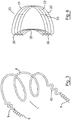
- a device according to a further embodiment of the invention, indicated generally by the reference numeral 30, and comprising a blocking member formed by an band 31 of four Nitinol wires 32 and reinforcing struts 33.
- the band 31 is generally semi-circular in shape and has a curved base 35 which is dimensioned to conform to the LVOT septum.
- the device 30 includes eight barbs 36 configured to anchor the device in-situ against the LVOT septum.
- FIG. 7 there is provided a further illustration of the device of Fig. 3 in-situ within the left ventricle of the heart, and anchored between the LVOT 7 septum and the left ventricular mid-septum 8.
- the blocking member 4 is a cage formed from a plurality of longitudinal struts 41 and one radial strut 42.
- the device comprises an elongated arm 43 formed of wire, a fixation screw 44 disposed at a distal end of the arm 43, and a transition zone 45 comprising a crimped section of the wire arm 43.
- the device is anchored into the apex 46 of the left ventricular septum.
- a device according to a further embodiment of the invention, indicated generally by the reference numeral 50, shown anchored in-situ within the left ventricle of the heart.
- the blocking member 4 is a helical member.
- the device comprises an elongated arm 53 formed of wire, a fixation screw 54 disposed at a distal end of the arm 53, and a transition zone 55 comprising a crimped section of the wire arm 53.
- the device is anchored above the apex 46 of the left ventricular septum.
- the blocking member 4 is curved band formed of Nitinol wires 61 and having a proximal end bearing a fixation screw 62 and a distal end bearing a second fixation screw 63.
- the screw 62 is anchored into the LVOT septum 7 and the fixation screw is anchored into the left ventricular mid-septum 8.
- the device comprises an elongated arm 73 formed of wire, a fixation screw 74 disposed at a distal end of the arm 73, and a disc-shaped blocking member 75 disposed on a proximal end of the arm 73.
- the device is anchored into the lateral wall of the left ventricle 77.
- the blocking member 4 is an arm formed from two substantially rigid Nitinol wires 81.
- the device comprises an elongated arm 83 formed of Nitinol wire, and a fixation screw 84 disposed at a distal end of the arm 83. The device is anchored into the apex 46 of the left ventricular septum.
- a device according to a further embodiment of the invention, indicated generally by the reference numeral 90, shown anchored in-situ across the left ventricle of the heart from the anterior wall to the posterior wall.
- the device comprises an elongated arm 93 formed of Nitinol wire, a middle section of which acts as the blocking member, and fixation screws 94, 95 disposed at each end of the arm 93.
- the device is anchored between the anterior and posterior walls of the left ventricle.
- the blocking member 4 is a cylindrical cage formed of braided Nitinol wires 101 and a series of anchoring barbs 102 disposed across one end of the cage that are anchored into the left ventricular septum 7.
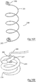
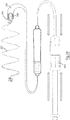
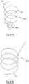
- a device according to a further embodiment of the invention, indicated generally by the reference numeral 200 and comprising a blocking member formed of a helical coil 201 having a proximal anchoring element 202 and distal anchoring element 203 formed at the end of the coil 201 and longitudinally aligned along a side of the coil to enable engagement with tissue adjacent the coil 201.
- a blocking member formed of a helical coil 201 having a proximal anchoring element 202 and distal anchoring element 203 formed at the end of the coil 201 and longitudinally aligned along a side of the coil to enable engagement with tissue adjacent the coil 201.
- the distal anchoring element 202 comprises a corkscrew anchor 204 with a piercing tip 206 at a distal end and a diametrical head 207 at a proximal end having a through-hole for receipt of a stem 208 formed on a distal end 209 of the coil 201, allowing the corkscrew anchor 204 rotate freely with respect to the coil 201.
- the proximal anchoring element has a similar construction to the distal anchoring element with the exception that the diametrical head 207 is disposed at the proximal end, and the piercing tip 206 is disposed at the distal end, of the corkscrew anchor 204, and a stem 210 formed on a proximal end of the coil 201 extends up through the corkscrew anchor 204.
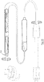
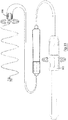
- the delivery device comprises a catheter 300 having a proximal end 301 with control handle elements 302, 303, and a distal end 304 configured to receive the device 200.
- the distal end 304 of the catheter comprises an outer sheath 305, an inner sheath 306, and a mid sheath 307 disposed between the outer and inner sheaths.
- the outer sheath is movable from an extended position shown in Fig, 17A to a withdrawn position shown in Fig. 17B by actuation of the handle element 302, exposing the distal corkscrew anchor 204.
- the mid sheath is movable from an extended position shown in Fig, 17B to a withdrawn position shown in Fig. 17C by actuation of the handle 302, exposing the device 200 including the proximal corkscrew anchor 204.
- the inner sheath 306 is rotatable in response to rotation of the control handle element 303.
- a distal end of the inner sheath 306 includes a diametrical slot 310 configured to receive the diametrical head 207 of the proximal corkscrew anchor 204 in a snap-fit manner.
- This arrangement allows the user remotely rotate the anchor 204 into engagement with adjacent tissue by means of rotation of the control handle element 303 and consequent rotation of the inner sheath 306.
- the distal end of the outer sheath 305 includes a similar diametrical slot 310 for engagement with the diametrical head 207 of the distal corkscrew anchor 204.
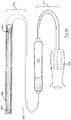
- the delivery device 300 is shown with the device 200 in-situ, with the proximal anchoring corkscrew 202 engaged with the distal end of the inner sheath 306, the distal anchoring corkscrew 203 engaged with the distal end of the mid sheath 307 and exposed on an outer surface of the mid sheath, and the coil stretched out within the mid sheath 307.
- the outer sheath 305 is fully extended fully covering the mid sheath, and the catheter 300 is extended along the right femoral vein into the heart until the distal end 304 is disposed in position within the left ventricle of the heath adjacent the LVOT septum and left ventricle mid septum.
- the control handle element 302 is actuated as illustrated to partially retract the outer sheath 305 exposing the distal corkscrew anchor 203.
- the catheter 300 is then rotated as illustrated to drive the anchor 203 into engagement with the adjacent tissue. Referring to Fig.
- the outer sheath 305 is then fully retracted by actuation of the control handle element 302, and the distal anchor 203 is released from the mid sheath 307 by actuation of a button 311 on the control handle element 303.
- the control handle element 303 is further actuated to fully withdraw the mid sheath 307, and the inner sheath 306 is slightly advanced as illustrated, exposing the coil 201 and proximal anchor 202.
- the inner sheath 306 is rotated by actuation of the control handle element 303, driving the proximal anchor element 202 into engagement with adjacent tissue, and the catheter 300 is then retracted leaving the device in-situ in the left ventricle of the heart in a position to prevent systolic anterior motion of the mitral valve leaflet.
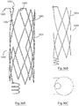
- an implantable intracardiac device comprising a blocking member formed of a generally cylindrical cage 401 having a proximal anchoring element 402 and distal anchoring element 403 formed at the ends of the cylindrical cage 401 and longitudinally aligned along a side of the cylindrical cage to enable engagement with tissue adjacent the blocking member.
- the cylindrical cage comprises longitudinal struts 405 and diamond shaped radial struts 406 connecting the longitudinal struts 405, the configuration allowing radial expansion of the device from a relaxed expanded configuration shown in Fig. 24A to a radially contracted configuration suitable for delivery in a delivery catheter.
- the distal anchoring element 403 comprises a corkscrew anchor 404 that is attached to, and extends away from, an end of a longitudinal strut 405 of the cylindrical cage and has a piercing tip 406 at a free end.
- the proximal anchoring element 402 has a similar construction to the distal anchoring element.
- the delivery device comprises a catheter 500 having a distal end 501 with control handle elements 502, 503, and a proximal end 504 configured to receive the device 400.
- the distal end 504 of the catheter comprises an outer sheath 505 and an inner sheath 506.
- the inner sheath 506 comprises an elongated longitudinal slot 507 that has a length similar to the length of the device 400 when in a radially contracted configuration.
- the slot 507 allows the cylindrical mesh 401 (in a radially contracted configuration) to be threaded along the inside of the inner sheath 506 while the distal and proximal corkscrew anchors 404 are threaded along an outside of the inner sheath.
- the outer sheath 505 is movable from an extended position shown in Fig, 25A to a withdrawn position shown in Fig. 25B by actuation of the handle element 502, exposing the inner sheath 506 and distal and proximal corkscrew anchors 404.
- the inner sheath is movable from an extended position shown in Fig, 25B to a withdrawn position shown in Fig. 25C by actuation of the handle 503, releasing the device 400.
- Figs 26 to 29 the use of the catheter 500 to deliver the implantable intracardiac device 400 percutaneously to the left ventricle of the heart and anchoring it in position will be described in more detail.
- the delivery device 500 is shown with the implantable intracardiac device 400 in-situ, with the proximal and distal anchoring corkscrews 404 spaced apart along the outside of the inner sheath 506, and the cylindrical mesh disposed within the inner sheath 506.
- the outer sheath 505 is fully extended fully covering the inner sheath 506, and the catheter 500 is extended along the right femoral vein into the heart until the distal end 504 is disposed in position within the left ventricle of the heath adjacent the LVOT septum and left ventricle mid septum.
- the control handle element 502 is actuated as illustrated to fully retract the outer sheath 505 exposing the distal and proximal corkscrew anchors 404.
- the catheter 500 is then rotated as illustrated to drive the two anchors 404 into engagement with the adjacent tissue. Referring to Fig.
- the catheter 500 is then retracted which results in retraction of the inner sheath 506 allowing the cylindrical cage 401 expand and leaving the device in-situ in the left ventricle of the heart in a position to prevent systolic anterior motion of the mitral valve leaflet.
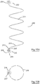
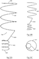
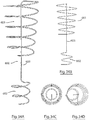
- an implantable intracardiac device according to an alternative embodiment of the invention, indicated generally by the reference numeral 600 and comprising a blocking member in the form of a helical coil 601, distal anchoring means in the form of a spaced apart co-axial helical coil 602 having a diameter smaller than the helical coil 601, and a stem 603 connecting the coils 601 and 602 that is at an angle to a longitudinal axis of the device.
- a proximal end 604 of the coil 601 projects slightly outside of the footprint of the coil 601 and likewise a distal end 605 of the coil 602 projects slightly outside of the footprint of the coil 602.
- the distal and proximal ends 604, 605 are provided with piercing tips.
- the device is positioned in the left ventricle of the heart as previously described and the device is rotated to drive the coil 602 fully into engagement with adjacent tissue which approximates to about three full turns. The device is then further rotated to drive the proximal end 604 of coil 601 into the adjacent tissue.
- FIG. 32A a further embodiment of the invention indicated generally by reference numeral 700 in which parts described with reference to the embodiment of Figs 30 and 31 are assigned the same reference numerals.
- the anchoring coil 602 is eccentrically disposed with respect to the blocking coil 601 with an edge of the coils overlapping in plain? view.
- the use of this embodiment is the same as that described with reference to the embodiment of Figs 30 and 31 .
- FIG. 800 there is illustrated a further embodiment of the invention indicated generally by reference numeral 800 in which parts described with reference to the embodiment of Figs 30 and 31 are assigned the same reference numerals.
- the anchoring coil 602 and blocking coil 601 are connected by a stem 603 that extends from a proximal end of the anchoring coil 602 up through a lumen of the blocking coil 601 and is attached to the blocking at a proximal end thereof.
- the blocking coil 601 tapers slightly towards a distal end thereof.
- the use of this embodiment is the same as that described with reference to the embodiment of Figs 30 and 31 .
- the blocking coil 601 comprises a proximal coil 902 and a distal coil 903 connected by a stem 903 that runs parallel to the stem 603.
- the use of this embodiment is the same as that described with reference to the embodiment of Figs 30 and 31 .
- FIG. 10A, B, C and D there is illustrated a further embodiment of the implantable intracardiac device of the invention indicated generally by reference numeral 1000 and comprising a cylindrical body 1001 formed of interconnected diagonal struts 1002.
- Three anchoring barbs 1003 are provided on a proximal end of the body at the end of struts, and an anchoring coil 1004 is provided at a distal end of the body 1001 and on the same side of the body as the anchoring barbs 1003.
- the provision of a cylindrical body formed of diagonal struts as opposed to a helical coil reduces the vertical deformation of the device in use.
- FIG. 1100 there is illustrated a further embodiment of the implantable intracardiac device of the invention indicated generally by reference numeral 1100 and comprising a cylindrical body 1101 formed of series of interconnected loops 1102.
- One anchoring barb 1103 is provided on a proximal end of the body, and an anchoring coil 1104 is provided at a distal end of the body 1001 and on the same side of the body as the anchoring barbs 1003.
- proximal anchoring means are provided by an anchoring coil 1201.
- FIG. 39A, B and C a further embodiment of the implantable intracardiac device of the invention is illustrated.
- the device is implanted in the cardiac catheterization lab while the patient is conscious. Under local anesthetic, an 8F sheath is inserted in the right femoral vein.
- the 8F sheath is then exchanged to a 71cm deflectable sheath (e.g. Agilis SJM).
- a 71cm deflectable sheath e.g. Agilis SJM.
- a transseptal approach is used to access the left ventricle (LV) with the deflectable sheath across the mitral valve.
- the aortic valve is crossed retrogradely with a 0.032" guidewire, over which the deflectable sheath with the dilator is advanced to the left ventricle.
- the delivery sheath is removed.
- the patient is anticoagulated with heparin during the procedure and for 24 hours post procedure and discharged home 24 hours post procedure on dual antiplatelet therapy (e.g. aspirin and clopidogrel) for three months (as is currently performed in patients undergoing mitral annuloplasty ring implantation, LA appendage closure device implantation, ASD and VSD closure device implantation procedures).
- dual antiplatelet therapy e.g. aspirin and clopidogrel
- a lead locking stylet or laser extraction system should not be required.
- the device may be retracted once grabbed by a retrieval wire and the screws removed by direct traction using flexibility of screw material without being unscrewed (this is currently often necessary with pacemaker lead extraction whereby it may not be possible to advance a stylet to the distal fixation screw or to transmit counter-clockwise torque to the distal screw).
- a docking loop is available as an engagement site for a retrieval catheter at the base of each active fixation screw.
- An implantable endocardial device therapy for SAM in HOCM Obviates the requirement for surgical myectomy or alcohol septal ablation in HOCM patients with SAM.
- the efficacy of the device can be assessed acutely in real time during implantation to ensure optimal sizing and deployment.
- LVOT left ventricular outflow tract
- the Anti-SAM device is easily deployed and the threshold for intervention would therefore be less than for a surgical myectomy which requires open heart surgery and cardiopulmonary bypass. Surgical myectomy also carries a risk of causing a VSD which is avoided by the device.
- the Anti-SAM device also obviates the requirement for papillary muscle reinsertion and mitral annuloplasty which is often performed concomitantly with a surgical myectomy.
- the device carries a lower risk to the patient than inducing a myocardial infarction with alcohol (TASH procedure) and carries a lower risk of causing complete AV conduction block and permanent pacemaker requirement.
Landscapes
- Health & Medical Sciences (AREA)
- Life Sciences & Earth Sciences (AREA)
- Surgery (AREA)
- Heart & Thoracic Surgery (AREA)
- Public Health (AREA)
- Vascular Medicine (AREA)
- Engineering & Computer Science (AREA)
- Biomedical Technology (AREA)
- Veterinary Medicine (AREA)
- General Health & Medical Sciences (AREA)
- Animal Behavior & Ethology (AREA)
- Molecular Biology (AREA)
- Medical Informatics (AREA)
- Nuclear Medicine, Radiotherapy & Molecular Imaging (AREA)
- Reproductive Health (AREA)
- Cardiology (AREA)
- Oral & Maxillofacial Surgery (AREA)
- Transplantation (AREA)
- Prostheses (AREA)
Claims (15)
- Implantierbare intrakardiale Vorrichtung (1) zur Prävention von systolischer anteriorer Bewegung des anterioren Mitralklappensegels in den linksventrikulären Ausflusstrakt ohne Inhibierung des Blutflusses durch den linksventrikulären Ausflusstrakt, wobei die Vorrichtung Folgendes umfasst: ein Blockierungselement (4), das für die Implantierung innerhalb des linken Ventrikels des Herzens konfiguriert ist, und ein Verankerungselement (6), das für die Verankerung der Vorrichtung an dem interventrikulären Septum konfiguriert ist, wodurch die Vorrichtung, wenn in dem interventrikulären Septum verankert, geeignet ist, um eine in-situ-Blockierung von systolischer anteriorer Bewegung des anterioren Mitralklappensegels in den linksventrikulären Ausflusstrakt zu bewirken, wobei das Blockierungselement für die Implantierung innerhalb des linken Ventrikels des Herzens ohne Kompression oder Umformung des Mitralklappenanulus konfiguriert ist und wobei das Blockierungselement eine allgemein zylinderförmige wendelförmige Spirale umfasst, die ein hohles Lumen für den Durchgang von Blut aufweist, wobei die wendelförmige Spirale eine Länge von 4-6 cm aufweist und sich nach innen in Richtung eines distalen Endes davon von einem proximalen radialen Durchmesser von 2-3 cm bis zu einem distalen radialen Durchmesser von 0,5 bis 1,5 cm verjüngt.
- Implantierbare intrakardiale Vorrichtung nach Anspruch 1, in der die Vorrichtung zur radialen Expansion von einer zusammengezogenen Ausrichtung, die für die transluminale Abgabe an den linken Ventrikel des Herzens innerhalb eines geeigneten Abgabevehikels geeignet ist, und einer expandierten Ausrichtung, die für den Einsatz innerhalb des linken Ventrikels des Herzens geeignet ist, konfiguriert ist.
- Implantierbare intrakardiale Vorrichtung nach einem vorstehenden Anspruch, in der die Vorrichtung ein weiteres Verankerungselement (5) umfasst, das für die Verankerung der Vorrichtung in situ innerhalb des linken Ventrikels an einer Wand des linken Ventrikels konfiguriert ist.
- Implantierbare intrakardiale Vorrichtung nach Anspruch 3, in der das Verankerungselement für den Eingriff in eine Wand des linken Ventrikels bei Drehung der Vorrichtung angrenzend zur Wand konfiguriert ist.
- Implantierbare intrakardiale Vorrichtung nach Anspruch 4, in der das Verankerungselement eine wendelförmige Spirale ist.
- Implantierbare intrakardiale Vorrichtung nach einem der Ansprüche 3 bis 5, in der das Verankerungselement drehbar an dem Blockierungselement angebracht ist.
- Implantierbare intrakardiale Vorrichtung nach einem der Ansprüche 3 bis 5, die zwei Verankerungselemente einschließt.
- Implantierbare intrakardiale Vorrichtung nach Anspruch 7, die ein erstes Verankerungselement, das an einem proximalen Ende des Blockierungselements angeordnet ist, und ein zweites Verankerungselement, das an einem distalen Ende des Blockierungselements angeordnet ist, einschließt.
- Implantierbare intrakardiale Vorrichtung nach Anspruch 8, in der das erste und zweite Verankerungselement längs ausgerichtet sind.
- Implantierbare intrakardiale Vorrichtung nach einem der Ansprüche 5 bis 9, in der das Blockierungselement ein allgemein zylinderförmiger Körper ist und in der die Verankerungsspirale von dem allgemein zylinderförmigen Körper beabstandet ist und koaxial dazu vorliegt.
- Implantierbare intrakardiale Vorrichtung nach einem der Ansprüche 5 bis 9, in der das Blockierungselement ein allgemein zylinderförmiger Körper ist und in der die Verankerungsspirale von dem allgemein zylinderförmigen Körper beabstandet ist und exzentrisch dazu vorliegt.
- Implantierbare intrakardiale Vorrichtung nach Anspruch 11, die ein Übergangselement umfasst, das zwischen einem Verankerungselement und dem Blockierungselement angeordnet ist.
- Implantierbare intrakardiale Vorrichtung nach einem der Ansprüche 3 bis 12, in der das Verankerungselement zur Verankerung der Vorrichtung an der Wand des linken Ventrikels konfiguriert ist.
- Implantierbare intrakardiale Vorrichtung nach einem der Ansprüche 3 bis 12, in der das Verankerungselement zur Verankerung der Vorrichtung an dem interventrikulären Septum konfiguriert ist.
- Implantierbare intrakardiale Vorrichtung nach einem der Ansprüche 3 bis 12, die Folgendes einschließt: ein proximales Verankerungselement, das zur Verankerung eines proximalen Endes der Vorrichtung an dem Septum des linksventrikulären Ausflusstrakts (LVOT) konfiguriert ist, und ein distales Verankerungselement, das zur Verankerung des distalen Endes der Vorrichtung an dem linksventrikulären Septum (a) zwischen dem LVOT-Septum und dem Apex des linksventrikulären Septums oder (b) an, über oder benachbart zu dem Apex des linksventrikulären Septums konfiguriert ist; und/oder die Folgendes einschließt: ein proximales Verankerungselement, das zur Verankerung eines proximalen Endes der Vorrichtung an der aortomitralen Kontinuität konfiguriert ist, und ein distales Verankerungselement, das zur Verankerung des distalen Endes der Vorrichtung über oder benachbart zu dem Apex des linksventrikulären Septums konfiguriert ist; und/oder die Folgendes umfasst: ein proximales Verankerungselement, das zur Verankerung eines proximalen Endes der Vorrichtung an dem linksventrikulären Septum konfiguriert ist, und ein distales Verankerungselement, das zur Verankerung des distalen Endes der Vorrichtung an der Seitenwand des linken Ventrikels konfiguriert ist.
Applications Claiming Priority (2)
| Application Number | Priority Date | Filing Date | Title |
|---|---|---|---|
| EP14199443 | 2014-12-19 | ||
| PCT/EP2015/080821 WO2016097411A2 (en) | 2014-12-19 | 2015-12-21 | An implantable intracardiac device for treatment of dynamic left ventricular outflow tract obstruction by preventing systolic anterior motion of the mitral valve leaflet into the left ventricular outflow tract |
Publications (2)
| Publication Number | Publication Date |
|---|---|
| EP3244809A2 EP3244809A2 (de) | 2017-11-22 |
| EP3244809B1 true EP3244809B1 (de) | 2020-02-05 |
Family
ID=52231941
Family Applications (1)
| Application Number | Title | Priority Date | Filing Date |
|---|---|---|---|
| EP15832799.9A Active EP3244809B1 (de) | 2014-12-19 | 2015-12-21 | Implantierbare intrakardiale vorrichtung |
Country Status (2)
| Country | Link |
|---|---|
| EP (1) | EP3244809B1 (de) |
| WO (1) | WO2016097411A2 (de) |
Cited By (7)
| Publication number | Priority date | Publication date | Assignee | Title |
|---|---|---|---|---|
| US10912644B2 (en) | 2018-10-05 | 2021-02-09 | Shifamed Holdings, Llc | Prosthetic cardiac valve devices, systems, and methods |
| US11471282B2 (en) | 2019-03-19 | 2022-10-18 | Shifamed Holdings, Llc | Prosthetic cardiac valve devices, systems, and methods |
| US11833034B2 (en) | 2016-01-13 | 2023-12-05 | Shifamed Holdings, Llc | Prosthetic cardiac valve devices, systems, and methods |
| US12053371B2 (en) | 2020-08-31 | 2024-08-06 | Shifamed Holdings, Llc | Prosthetic valve delivery system |
| US12201521B2 (en) | 2021-03-22 | 2025-01-21 | Shifamed Holdings, Llc | Anchor position verification for prosthetic cardiac valve devices |
| US12290456B2 (en) | 2018-08-21 | 2025-05-06 | Shifamed Holdings, Llc | Prosthetic cardiac valve devices, systems, and methods |
| US12403008B2 (en) | 2018-10-19 | 2025-09-02 | Shifamed Holdings, Llc | Adjustable medical device |
Families Citing this family (3)
| Publication number | Priority date | Publication date | Assignee | Title |
|---|---|---|---|---|
| CN109480965B (zh) * | 2018-12-29 | 2024-09-13 | 储勤军 | 非体外循环技术下经心尖室间隔心肌旋切系统 |
| CN115607339B (zh) * | 2022-11-07 | 2023-02-28 | 广东捍宇医疗科技有限公司 | 瓣膜装置及瓣膜装置植入系统 |
| CN115414156B (zh) * | 2022-11-07 | 2023-07-14 | 广东捍宇医疗科技有限公司 | 瓣膜装置及瓣膜装置植入系统 |
Family Cites Families (7)
| Publication number | Priority date | Publication date | Assignee | Title |
|---|---|---|---|---|
| EP1395214B1 (de) * | 2001-04-27 | 2014-02-26 | Cormend Technologies, LLC | Prävention einer durch einen myokardinfarkt ausgelösten ventrikelexpansion und remodellierung |
| WO2007030823A2 (en) * | 2005-09-09 | 2007-03-15 | Edwards Lifesciences Corporation | Device and method for reshaping mitral valve annulus |
| US8029556B2 (en) * | 2006-10-04 | 2011-10-04 | Edwards Lifesciences Corporation | Method and apparatus for reshaping a ventricle |
| US8249722B2 (en) | 2007-11-29 | 2012-08-21 | St. Jude Medical Ab | Active fixation element |
| CN103987341B (zh) * | 2011-01-04 | 2017-02-22 | 克利夫兰临床基金会 | 治疗心脏瓣膜返流的装置和方法 |
| WO2013016618A2 (en) * | 2011-07-27 | 2013-01-31 | The Cleveland Clinic Foundation | Apparatus, system, and method for treating a regurgitant heart valve |
| US20140100596A1 (en) * | 2012-10-09 | 2014-04-10 | Boston Scientific Scimed, Inc. | Centered balloon for the left atrial appendage |
-
2015
- 2015-12-21 WO PCT/EP2015/080821 patent/WO2016097411A2/en not_active Ceased
- 2015-12-21 EP EP15832799.9A patent/EP3244809B1/de active Active
Non-Patent Citations (1)
| Title |
|---|
| None * |
Cited By (10)
| Publication number | Priority date | Publication date | Assignee | Title |
|---|---|---|---|---|
| US11833034B2 (en) | 2016-01-13 | 2023-12-05 | Shifamed Holdings, Llc | Prosthetic cardiac valve devices, systems, and methods |
| US12290456B2 (en) | 2018-08-21 | 2025-05-06 | Shifamed Holdings, Llc | Prosthetic cardiac valve devices, systems, and methods |
| US10912644B2 (en) | 2018-10-05 | 2021-02-09 | Shifamed Holdings, Llc | Prosthetic cardiac valve devices, systems, and methods |
| US11672657B2 (en) | 2018-10-05 | 2023-06-13 | Shifamed Holdings, Llc | Prosthetic cardiac valve devices, systems, and methods |
| US11986389B2 (en) | 2018-10-05 | 2024-05-21 | Shifamed Holdings, Llc | Prosthetic cardiac valve devices, systems, and methods |
| US12419743B2 (en) | 2018-10-05 | 2025-09-23 | Shifamed Holdings, Llc | Prosthetic cardiac valve devices, systems, and methods |
| US12403008B2 (en) | 2018-10-19 | 2025-09-02 | Shifamed Holdings, Llc | Adjustable medical device |
| US11471282B2 (en) | 2019-03-19 | 2022-10-18 | Shifamed Holdings, Llc | Prosthetic cardiac valve devices, systems, and methods |
| US12053371B2 (en) | 2020-08-31 | 2024-08-06 | Shifamed Holdings, Llc | Prosthetic valve delivery system |
| US12201521B2 (en) | 2021-03-22 | 2025-01-21 | Shifamed Holdings, Llc | Anchor position verification for prosthetic cardiac valve devices |
Also Published As
| Publication number | Publication date |
|---|---|
| WO2016097411A3 (en) | 2016-10-27 |
| WO2016097411A2 (en) | 2016-06-23 |
| EP3244809A2 (de) | 2017-11-22 |
Similar Documents
| Publication | Publication Date | Title |
|---|---|---|
| US11160655B2 (en) | Implantable intracardiac device and methods thereof | |
| EP3244809B1 (de) | Implantierbare intrakardiale vorrichtung | |
| JP7661383B2 (ja) | 弁膜逆流の治療のための僧帽弁インプラント | |
| JP7715487B2 (ja) | 人工心臓弁を埋め込むための送達システム、方法および装置のためのシステム、方法および装置 | |
| US20210393404A1 (en) | Methods, systems and devices for cardiac valve repair | |
| US10624744B2 (en) | Treating dysfunctional cardiac tissue | |
| US7316706B2 (en) | Tensioning device, system, and method for treating mitral valve regurgitation | |
| EP2760347B1 (de) | Over-the-wire herzimplantat-abgabesystem zur behandlung von herzinsuffizienz und anderen leiden | |
| EP2313152B1 (de) | Kardiale verankerungsstrukturen | |
| US7144363B2 (en) | Systems for heart treatment | |
| US7655040B2 (en) | Cardiac valve annulus reduction system | |
| CN202821715U (zh) | 腱索置换装置 | |
| US20060282161A1 (en) | Valve annulus reduction system | |
| EP2023822A2 (de) | Katheterbasierte mitraklappen-reparaturmethode und gerät | |
| JP2023515809A (ja) | 経カテーテル弁リード及び弁要素 | |
| US20230372102A1 (en) | Cardiac anchoring solutions | |
| US20250114190A1 (en) | Heart valve prosthesis | |
| EP3878410A1 (de) | Annuloplastievorrichtung | |
| JP2023552437A (ja) | 心臓弁輪を再成形するためのデバイス、方法、及びシステム | |
| EP3593758A1 (de) | Implantierbare herzklappenvorrichtung und -system | |
| HK1209616B (en) | Device, system, and method for transcatheter treatment of valve regurgitation |
Legal Events
| Date | Code | Title | Description |
|---|---|---|---|
| STAA | Information on the status of an ep patent application or granted ep patent |
Free format text: STATUS: THE INTERNATIONAL PUBLICATION HAS BEEN MADE |
|
| PUAI | Public reference made under article 153(3) epc to a published international application that has entered the european phase |
Free format text: ORIGINAL CODE: 0009012 |
|
| STAA | Information on the status of an ep patent application or granted ep patent |
Free format text: STATUS: REQUEST FOR EXAMINATION WAS MADE |
|
| 17P | Request for examination filed |
Effective date: 20170719 |
|
| AK | Designated contracting states |
Kind code of ref document: A2 Designated state(s): AL AT BE BG CH CY CZ DE DK EE ES FI FR GB GR HR HU IE IS IT LI LT LU LV MC MK MT NL NO PL PT RO RS SE SI SK SM TR |
|
| AX | Request for extension of the european patent |
Extension state: BA ME |
|
| DAV | Request for validation of the european patent (deleted) | ||
| DAX | Request for extension of the european patent (deleted) | ||
| GRAP | Despatch of communication of intention to grant a patent |
Free format text: ORIGINAL CODE: EPIDOSNIGR1 |
|
| STAA | Information on the status of an ep patent application or granted ep patent |
Free format text: STATUS: GRANT OF PATENT IS INTENDED |
|
| INTG | Intention to grant announced |
Effective date: 20190704 |
|
| GRAS | Grant fee paid |
Free format text: ORIGINAL CODE: EPIDOSNIGR3 |
|
| GRAA | (expected) grant |
Free format text: ORIGINAL CODE: 0009210 |
|
| STAA | Information on the status of an ep patent application or granted ep patent |
Free format text: STATUS: THE PATENT HAS BEEN GRANTED |
|
| AK | Designated contracting states |
Kind code of ref document: B1 Designated state(s): AL AT BE BG CH CY CZ DE DK EE ES FI FR GB GR HR HU IE IS IT LI LT LU LV MC MK MT NL NO PL PT RO RS SE SI SK SM TR |
|
| REG | Reference to a national code |
Ref country code: GB Ref legal event code: FG4D |
|
| REG | Reference to a national code |
Ref country code: AT Ref legal event code: REF Ref document number: 1229383 Country of ref document: AT Kind code of ref document: T Effective date: 20200215 |
|
| REG | Reference to a national code |
Ref country code: DE Ref legal event code: R096 Ref document number: 602015046516 Country of ref document: DE |
|
| REG | Reference to a national code |
Ref country code: IE Ref legal event code: FG4D |
|
| REG | Reference to a national code |
Ref country code: CH Ref legal event code: EP |
|
| REG | Reference to a national code |
Ref country code: NL Ref legal event code: MP Effective date: 20200205 |
|
| PG25 | Lapsed in a contracting state [announced via postgrant information from national office to epo] |
Ref country code: FI Free format text: LAPSE BECAUSE OF FAILURE TO SUBMIT A TRANSLATION OF THE DESCRIPTION OR TO PAY THE FEE WITHIN THE PRESCRIBED TIME-LIMIT Effective date: 20200205 Ref country code: PT Free format text: LAPSE BECAUSE OF FAILURE TO SUBMIT A TRANSLATION OF THE DESCRIPTION OR TO PAY THE FEE WITHIN THE PRESCRIBED TIME-LIMIT Effective date: 20200628 Ref country code: NO Free format text: LAPSE BECAUSE OF FAILURE TO SUBMIT A TRANSLATION OF THE DESCRIPTION OR TO PAY THE FEE WITHIN THE PRESCRIBED TIME-LIMIT Effective date: 20200505 Ref country code: RS Free format text: LAPSE BECAUSE OF FAILURE TO SUBMIT A TRANSLATION OF THE DESCRIPTION OR TO PAY THE FEE WITHIN THE PRESCRIBED TIME-LIMIT Effective date: 20200205 |
|
| REG | Reference to a national code |
Ref country code: LT Ref legal event code: MG4D |
|
| PG25 | Lapsed in a contracting state [announced via postgrant information from national office to epo] |
Ref country code: BG Free format text: LAPSE BECAUSE OF FAILURE TO SUBMIT A TRANSLATION OF THE DESCRIPTION OR TO PAY THE FEE WITHIN THE PRESCRIBED TIME-LIMIT Effective date: 20200505 Ref country code: IS Free format text: LAPSE BECAUSE OF FAILURE TO SUBMIT A TRANSLATION OF THE DESCRIPTION OR TO PAY THE FEE WITHIN THE PRESCRIBED TIME-LIMIT Effective date: 20200605 Ref country code: HR Free format text: LAPSE BECAUSE OF FAILURE TO SUBMIT A TRANSLATION OF THE DESCRIPTION OR TO PAY THE FEE WITHIN THE PRESCRIBED TIME-LIMIT Effective date: 20200205 Ref country code: GR Free format text: LAPSE BECAUSE OF FAILURE TO SUBMIT A TRANSLATION OF THE DESCRIPTION OR TO PAY THE FEE WITHIN THE PRESCRIBED TIME-LIMIT Effective date: 20200506 Ref country code: LV Free format text: LAPSE BECAUSE OF FAILURE TO SUBMIT A TRANSLATION OF THE DESCRIPTION OR TO PAY THE FEE WITHIN THE PRESCRIBED TIME-LIMIT Effective date: 20200205 Ref country code: SE Free format text: LAPSE BECAUSE OF FAILURE TO SUBMIT A TRANSLATION OF THE DESCRIPTION OR TO PAY THE FEE WITHIN THE PRESCRIBED TIME-LIMIT Effective date: 20200205 |
|
| PG25 | Lapsed in a contracting state [announced via postgrant information from national office to epo] |
Ref country code: NL Free format text: LAPSE BECAUSE OF FAILURE TO SUBMIT A TRANSLATION OF THE DESCRIPTION OR TO PAY THE FEE WITHIN THE PRESCRIBED TIME-LIMIT Effective date: 20200205 |
|
| PG25 | Lapsed in a contracting state [announced via postgrant information from national office to epo] |
Ref country code: DK Free format text: LAPSE BECAUSE OF FAILURE TO SUBMIT A TRANSLATION OF THE DESCRIPTION OR TO PAY THE FEE WITHIN THE PRESCRIBED TIME-LIMIT Effective date: 20200205 Ref country code: SM Free format text: LAPSE BECAUSE OF FAILURE TO SUBMIT A TRANSLATION OF THE DESCRIPTION OR TO PAY THE FEE WITHIN THE PRESCRIBED TIME-LIMIT Effective date: 20200205 Ref country code: EE Free format text: LAPSE BECAUSE OF FAILURE TO SUBMIT A TRANSLATION OF THE DESCRIPTION OR TO PAY THE FEE WITHIN THE PRESCRIBED TIME-LIMIT Effective date: 20200205 Ref country code: LT Free format text: LAPSE BECAUSE OF FAILURE TO SUBMIT A TRANSLATION OF THE DESCRIPTION OR TO PAY THE FEE WITHIN THE PRESCRIBED TIME-LIMIT Effective date: 20200205 Ref country code: ES Free format text: LAPSE BECAUSE OF FAILURE TO SUBMIT A TRANSLATION OF THE DESCRIPTION OR TO PAY THE FEE WITHIN THE PRESCRIBED TIME-LIMIT Effective date: 20200205 Ref country code: CZ Free format text: LAPSE BECAUSE OF FAILURE TO SUBMIT A TRANSLATION OF THE DESCRIPTION OR TO PAY THE FEE WITHIN THE PRESCRIBED TIME-LIMIT Effective date: 20200205 Ref country code: RO Free format text: LAPSE BECAUSE OF FAILURE TO SUBMIT A TRANSLATION OF THE DESCRIPTION OR TO PAY THE FEE WITHIN THE PRESCRIBED TIME-LIMIT Effective date: 20200205 Ref country code: SK Free format text: LAPSE BECAUSE OF FAILURE TO SUBMIT A TRANSLATION OF THE DESCRIPTION OR TO PAY THE FEE WITHIN THE PRESCRIBED TIME-LIMIT Effective date: 20200205 |
|
| REG | Reference to a national code |
Ref country code: DE Ref legal event code: R097 Ref document number: 602015046516 Country of ref document: DE |
|
| REG | Reference to a national code |
Ref country code: AT Ref legal event code: MK05 Ref document number: 1229383 Country of ref document: AT Kind code of ref document: T Effective date: 20200205 |
|
| PLBE | No opposition filed within time limit |
Free format text: ORIGINAL CODE: 0009261 |
|
| STAA | Information on the status of an ep patent application or granted ep patent |
Free format text: STATUS: NO OPPOSITION FILED WITHIN TIME LIMIT |
|
| 26N | No opposition filed |
Effective date: 20201106 |
|
| PG25 | Lapsed in a contracting state [announced via postgrant information from national office to epo] |
Ref country code: IT Free format text: LAPSE BECAUSE OF FAILURE TO SUBMIT A TRANSLATION OF THE DESCRIPTION OR TO PAY THE FEE WITHIN THE PRESCRIBED TIME-LIMIT Effective date: 20200205 Ref country code: AT Free format text: LAPSE BECAUSE OF FAILURE TO SUBMIT A TRANSLATION OF THE DESCRIPTION OR TO PAY THE FEE WITHIN THE PRESCRIBED TIME-LIMIT Effective date: 20200205 |
|
| PG25 | Lapsed in a contracting state [announced via postgrant information from national office to epo] |
Ref country code: PL Free format text: LAPSE BECAUSE OF FAILURE TO SUBMIT A TRANSLATION OF THE DESCRIPTION OR TO PAY THE FEE WITHIN THE PRESCRIBED TIME-LIMIT Effective date: 20200205 Ref country code: SI Free format text: LAPSE BECAUSE OF FAILURE TO SUBMIT A TRANSLATION OF THE DESCRIPTION OR TO PAY THE FEE WITHIN THE PRESCRIBED TIME-LIMIT Effective date: 20200205 |
|
| REG | Reference to a national code |
Ref country code: CH Ref legal event code: PL |
|
| PG25 | Lapsed in a contracting state [announced via postgrant information from national office to epo] |
Ref country code: MC Free format text: LAPSE BECAUSE OF FAILURE TO SUBMIT A TRANSLATION OF THE DESCRIPTION OR TO PAY THE FEE WITHIN THE PRESCRIBED TIME-LIMIT Effective date: 20200205 |
|
| REG | Reference to a national code |
Ref country code: BE Ref legal event code: MM Effective date: 20201231 |
|
| PG25 | Lapsed in a contracting state [announced via postgrant information from national office to epo] |
Ref country code: LU Free format text: LAPSE BECAUSE OF NON-PAYMENT OF DUE FEES Effective date: 20201221 |
|
| PG25 | Lapsed in a contracting state [announced via postgrant information from national office to epo] |
Ref country code: CH Free format text: LAPSE BECAUSE OF NON-PAYMENT OF DUE FEES Effective date: 20201231 Ref country code: LI Free format text: LAPSE BECAUSE OF NON-PAYMENT OF DUE FEES Effective date: 20201231 |
|
| PG25 | Lapsed in a contracting state [announced via postgrant information from national office to epo] |
Ref country code: TR Free format text: LAPSE BECAUSE OF FAILURE TO SUBMIT A TRANSLATION OF THE DESCRIPTION OR TO PAY THE FEE WITHIN THE PRESCRIBED TIME-LIMIT Effective date: 20200205 Ref country code: MT Free format text: LAPSE BECAUSE OF FAILURE TO SUBMIT A TRANSLATION OF THE DESCRIPTION OR TO PAY THE FEE WITHIN THE PRESCRIBED TIME-LIMIT Effective date: 20200205 Ref country code: CY Free format text: LAPSE BECAUSE OF FAILURE TO SUBMIT A TRANSLATION OF THE DESCRIPTION OR TO PAY THE FEE WITHIN THE PRESCRIBED TIME-LIMIT Effective date: 20200205 |
|
| PG25 | Lapsed in a contracting state [announced via postgrant information from national office to epo] |
Ref country code: MK Free format text: LAPSE BECAUSE OF FAILURE TO SUBMIT A TRANSLATION OF THE DESCRIPTION OR TO PAY THE FEE WITHIN THE PRESCRIBED TIME-LIMIT Effective date: 20200205 Ref country code: AL Free format text: LAPSE BECAUSE OF FAILURE TO SUBMIT A TRANSLATION OF THE DESCRIPTION OR TO PAY THE FEE WITHIN THE PRESCRIBED TIME-LIMIT Effective date: 20200205 |
|
| PG25 | Lapsed in a contracting state [announced via postgrant information from national office to epo] |
Ref country code: BE Free format text: LAPSE BECAUSE OF NON-PAYMENT OF DUE FEES Effective date: 20201231 |
|
| PGFP | Annual fee paid to national office [announced via postgrant information from national office to epo] |
Ref country code: GB Payment date: 20241216 Year of fee payment: 10 |
|
| PGFP | Annual fee paid to national office [announced via postgrant information from national office to epo] |
Ref country code: FR Payment date: 20241223 Year of fee payment: 10 |
|
| PGFP | Annual fee paid to national office [announced via postgrant information from national office to epo] |
Ref country code: IE Payment date: 20241216 Year of fee payment: 10 |
|
| PGFP | Annual fee paid to national office [announced via postgrant information from national office to epo] |
Ref country code: DE Payment date: 20241227 Year of fee payment: 10 |