EP3244489B1 - Bloc de jonction avec porte-repère apte à être fixé dans un puits de shunt - Google Patents
Bloc de jonction avec porte-repère apte à être fixé dans un puits de shunt Download PDFInfo
- Publication number
- EP3244489B1 EP3244489B1 EP16169285.0A EP16169285A EP3244489B1 EP 3244489 B1 EP3244489 B1 EP 3244489B1 EP 16169285 A EP16169285 A EP 16169285A EP 3244489 B1 EP3244489 B1 EP 3244489B1
- Authority
- EP
- European Patent Office
- Prior art keywords
- identification
- terminal block
- fastening portion
- insulating box
- relative
- Prior art date
- Legal status (The legal status is an assumption and is not a legal conclusion. Google has not performed a legal analysis and makes no representation as to the accuracy of the status listed.)
- Active
Links
Images


Classifications
-
- H—ELECTRICITY
- H01—ELECTRIC ELEMENTS
- H01R—ELECTRICALLY-CONDUCTIVE CONNECTIONS; STRUCTURAL ASSOCIATIONS OF A PLURALITY OF MUTUALLY-INSULATED ELECTRICAL CONNECTING ELEMENTS; COUPLING DEVICES; CURRENT COLLECTORS
- H01R9/00—Structural associations of a plurality of mutually-insulated electrical connecting elements, e.g. terminal strips or terminal blocks; Terminals or binding posts mounted upon a base or in a case; Bases therefor
- H01R9/22—Bases, e.g. strip, block, panel
- H01R9/24—Terminal blocks
- H01R9/2475—Means facilitating correct wiring, e.g. marking plates, identification tags
-
- H—ELECTRICITY
- H01—ELECTRIC ELEMENTS
- H01R—ELECTRICALLY-CONDUCTIVE CONNECTIONS; STRUCTURAL ASSOCIATIONS OF A PLURALITY OF MUTUALLY-INSULATED ELECTRICAL CONNECTING ELEMENTS; COUPLING DEVICES; CURRENT COLLECTORS
- H01R9/00—Structural associations of a plurality of mutually-insulated electrical connecting elements, e.g. terminal strips or terminal blocks; Terminals or binding posts mounted upon a base or in a case; Bases therefor
- H01R9/22—Bases, e.g. strip, block, panel
- H01R9/24—Terminal blocks
- H01R9/26—Clip-on terminal blocks for side-by-side rail- or strip-mounting
- H01R9/2625—Clip-on terminal blocks for side-by-side rail- or strip-mounting with built-in electrical component
- H01R9/2633—Clip-on terminal blocks for side-by-side rail- or strip-mounting with built-in electrical component with built-in switch
Definitions
- the present invention relates to an individual marker holder for an electrical terminal block, the terminal block comprising an insulating box having a rear face equipped with fixing elements enabling the terminal block to be fixed on a support rail according to an arrangement in in which a plurality of terminal blocks are arranged side by side on a same row oriented along the support rail.
- the invention also relates to a terminal block as such and to an arrangement comprising at least two terminal blocks arranged side by side in an adjacent manner on a support rail.
- a junction block is an electrical device comprising at least two connection terminals each making it possible to connect a corresponding electrical conductor, for example in the form of an electrically conductive wire.
- a terminal block also comprises at least one electrically conductive connecting strip for establishing the electrical connection between the two electrical conductors connected to the two connection terminals.
- connection terminals and the connecting strip constitutes a stage and it is known practice to design the terminal block so that it comprises one, two or three stage (s).
- terminal block can be designed so as to allow the installation of a shunt jumper making it possible to establish an electrical contact between two connecting bars respectively implanted in two different terminal blocks.
- these two terminal blocks can be mounted adjacent to the same support rail.
- the shunt jumper is put in place by inserting it, at each terminal block, in a shunt well provided in the insulating box.
- junction block (s) there is a problem of being able to identify the junction block (s) in a simple, efficient, practical and economical way. In fact, it is necessary to be able to locate and identify the function of the terminal block or of each stage, or else the general function sought.
- each terminal block it is known to equip each terminal block with an individual marker holder.
- a solution of this nature is described for example in the document DE2020080136609U1 or in the document DE102008058871B3 .
- the currently known solutions do not give complete satisfaction.
- the fixing of the marker holder requires the creation of an area dedicated to this function and / or requires fixing means dedicated to mounting the marker holder on the insulating box, which increases the overall bulk and the cost.
- the known solutions remain complex, expensive and impractical.
- the document GB1380533A describes a terminal block comprising a case, one main face of which is open to allow the installation of connection terminals and of the conductive strip.
- the rear face of the box comprises a foot capable of being snapped onto a rail of a cabinet.
- the front of the box has two holes for handling the clamping screws of the connection terminals. At the front face, between these two openings, the box defines a hollow allowing the installation of a shunt. Provision is also made for the presence of a one-piece separator which snaps into the hollow.
- the function of this separator is to electrically isolate two adjacent shunts to avoid their electrical connection in case of high voltage. It is expected that the separator can be equipped with an individual marking label, or collective with several adjacent blocks.
- the present invention aims to resolve all or part of the drawbacks listed above.
- the present invention relates to a terminal block according to claim 1.
- an individual marker holder for an electrical terminal block, the terminal block comprising an insulating box having a rear face equipped with fixing elements making it possible to fix the terminal block on a support rail according to an arrangement in which a plurality of terminal blocks are arranged side by side on a same row oriented along the support rail, the marker holder comprising a first fixing part configured so as to be able to be fixed by insertion in a shunt well formed in a front face of the insulating box of the junction block.
- the marker holder comprises a second identification part articulated relative to the first fixing part, so as to be able to be movable by pivoting with respect to the insulating box when the first fixing part is fixed in the shunt well, the second identification part comprising at least one identification portion, in particular making it possible to receive an identification mark.
- the second identification part is provided with a plurality of identification portions aligned with one another, in particular each allowing the reception of an identification mark.
- the pivot axis of the second identification part relative to the first fixing part is perpendicular to the direction in which the first fixing part is intended to be inserted into the shunt well and perpendicular to the direction in which the identification portions are staggered along the second identification portion.
- the first fixing part and the second identification part are formed in one and the same single piece, the articulation between the first fixing part and the second identification part being constituted by a zone locally elastically deformable of said one-piece part.
- first fixing part and the second identification part can be constituted by two distinct parts assembled with one another by pivoting securing elements allowing pivoting of the second identification part with respect to the first fixing part so as to constitute the articulation between the first fixing part and the second identification part.
- the marker holder comprises elements for angular indexing of the angular position occupied by the second identification part with respect to the first fixing part, in particular according to predetermined angular positions.
- the pivot axis conferred by the articulation of the second identification part with respect to the first fixing part is located at one end of the second identification part and is substantially aligned with said said part. at least one identification portion.
- the first fixing part has symmetry along a plane containing both the direction in which the first fixing part is intended to be inserted into the shunt well and the direction corresponding to the axis of pivoting around which the second identification part is articulated relative to the first fixing part, so that the marker holder can occupy two different configurations with respect to the insulating box varying from one another by a rotation of 180 degrees of the first fastening part around the direction of insertion into the shunt well.
- an electrical terminal block comprising an insulating box having a rear face equipped with fixing elements making it possible to fix the terminal block on a support rail according to an arrangement in which a plurality of terminal blocks are arranged side by side on the same row oriented in the direction of the support rail and a front face comprising at least one shunt well, the junction block comprising such a marker holder, the first fixing part of which is inserted into the well shunt.
- the marker holder comprising a second identification part having at least one identification portion and articulated relative to the first fixing part so as to be movable by pivoting relative to the insulating housing, the second part of 'identification varies at least between a lowered angular position with respect to the insulating box in which the second identification part is substantially parallel to the front face of the insulating box and an upright angular position in which the second identification part is substantially perpendicular locally on the front face of the insulating case, the first fixing part of the marker holder being stationary with respect to the insulating case during the change of angular position of the second identification part of the marker holder.
- the shunt well comprises an internal annular rib arranged at the level of its mouth towards the front face and included in a plane perpendicular to the direction in which the first fixing part is inserted into the shunt well and the first fixing part comprises an external annular groove in which the internal annular rib of the shunt well is inserted by elastic interlocking during the insertion of the first fixing part.
- the shunt well comprises an internal annular shoulder extending by a receiving bore on the side opposite the mouth of the shunt well on the front face of the insulating box and the first fixing part comprises a tenon elastically deformable end which is inserted into the receiving bore during the insertion of the first fixing part by means of an elastic deformation of the end pin.
- the width of the second fixing part counted along the direction in which the pivot axis of the second fixing part relative to the first fixing part is counted is equal to or less than the thickness of the insulating box of the counted terminal block in the direction in which the support rail is oriented when the terminal block is attached to the support rail.
- an arrangement comprising a support rail and at least two such junction blocks fixed by their rear faces so as to be arranged side by side in a same row oriented in the direction of the support rail, arrangement in which the door - marker fixed in the shunt well of the insulating box of one of the terminal blocks is independent of the marker holder fixed in the shunt well of the insulating box of the other of the junction blocks.
- the marker holder 10 is such that it individually equips a single terminal block 11 and makes it possible to identify at least one function intended to be fulfilled by the terminal block 11 on which it is. fixed. In other words, the marker holder 10 only identifies the functions performed by this terminal block 11.
- FIGS. 7 and 8 appended also show an example of an electrical terminal block 11 according to another aspect of the invention, the marker holder 10 of the Figures 1 to 6 being fixed to the insulating box 12 in a particular way which will be described later.
- the terminal block 11 is an electrical device comprising at least two connection terminals 13 each allowing to connect a corresponding electrical conductor (not shown), for example in the form of an electrically conductive wire.
- the terminal block 11 also comprises at least one electrically conductive connecting strip 14 to establish the electrical connection between the two electrical conductors connected to the two connection terminals 13.
- connection terminals 13 and the connecting strip 14 constitutes a stage.
- the variant illustrated on Figures 7 and 8 is a single-stage terminal block 11, but the terminal block 11 could either have two or three stages, depending on the applications associated with the terminal block 11 and depending on the needs of the users.
- the junction block 11 therefore comprises the insulating box 12 mentioned above, in which are mounted the two connection terminals 13 and the electrically conductive connecting strip (s) 14.
- Each connection terminal 13 may be of any nature, for example using fixing by screw or by contact spring, or else of the self-stripping type.
- the insulating box 12 has a rear face 15 equipped with fixing elements 16 making it possible to fix the terminal block 11 on a support rail (not shown) according to an arrangement in which a plurality of terminal blocks 11 are arranged side by side. on the same row oriented along the support rail.
- the fixing elements 16 can cooperate with the support rail according to a principle of snap-fastening or elastic interlocking.
- another aspect of the invention relates to an arrangement comprising the support rail and at least two terminal blocks 11 as described here, in other words a plurality of such terminal blocks 11, fixed by their rear faces so to be arranged side by side on the same row oriented in the direction of the support rail. It is understood that the number of terminal blocks 11 can be greater than or equal to 2.
- the direction X corresponds to the direction of the insulating box 12 which is oriented in the direction of the length of the support rail when the junction block 11 is fixed on the support rail.
- the dimension of the insulating box 12 in the direction X corresponds to its thickness.
- the Y direction corresponds to the direction of the insulating box 12 which is oriented in the width direction of the support rail when the junction block 11 is fixed to the support rail.
- the dimension of the insulating box 12 in the Y direction corresponds to its length.
- the Z direction corresponds to the direction of the insulating box 12 which is locally perpendicular to the wall where the support rail is fixed when the junction block 11 is fixed on the support rail.
- the dimension of the insulating box 12 in the Z direction corresponds to its height.
- the height and the length of the insulating box 12 are substantially equal to each other while the thickness is significantly less than the height and the length.
- the insulating box 12 also comprises a front face 17 comprising at least one shunt well 18.
- the number of shunt wells 18 can be greater than or equal to 1, depending on the applications and the needs of the users of the terminal block 11.
- a By way of nonlimiting example, the illustrated variant comprises two shunt wells 18.
- the two shunt wells 18 are offset with respect to each other along the length of the insulating box 11 which is counted in the direction Y.
- Each shunt well 18 extends in the Z direction.
- the rear and front faces 15, 17 are opposite in the Z direction.
- the marker holder 10 comprises a first fixing part 19 configured so as to be able to be fixed in the front face 17 of the insulating box 12 of the terminal block 11.
- the first fixing part 19 is configured so that its fixing on the front face 17 of the insulating box 12 is carried out by inserting it into one of the shunt wells 18 provided in the front face 17 of the insulating box 12 of the junction block 11.
- the junction block 11 therefore comprises such a marker holder 10, the first fixing part 19 of which is fixed in the front face 17 of the insulating box 12.
- the first fixing part 19 is inserted into one of the shunt wells. 18 provided in the front face 17 of the insulating box 12.
- shunt well is meant an opening made in the insulating box 12 so as to allow communication between the inside and the outside of the insulating box 12 and configured to allow the installation in this opening of a shunt element (not shown), otherwise known as a shunt jumper.
- the shunt element is inserted into two shunt wells 18 belonging to two adjacent terminal blocks 11 within the row of blocks 11 mounted on the support rail. The placement of the shunt element in the shunt wells 18 of the two adjacent terminal blocks 11 makes it possible to establish an electrical contact between two connecting bars 14 respectively located inside the insulating boxes 12 of the two terminal blocks. junction 11 adjacent.
- the marker holder 10 comprises a second identification part 20 articulated relative to the first fixing part 19.
- the second identification part 20 can therefore be movable by pivoting relative to the housing. insulator 12 when the first fixing part 19 is fixed in the shunt well 18 of the insulating box 12.
- the second identification part 20 comprises at least one identification portion 21.
- the pivot axis D1 conferred by the articulation of the second identification part 20 with respect to the first fixing part 19 is located at one end. of the second identification portion 20 and is substantially aligned with said at least one identification portion 21.
- said at least one identification portion 21 is offset with respect to the pivot axis D1 in a perpendicular direction to the direction of the pivot axis D1.
- substantially aligned is meant “exactly aligned” or “aligned within a given tolerance”, this given tolerance possibly being an angular tolerance or a dimensional tolerance counted in the plane perpendicular to the pivot axis D1.
- the angle formed, in the plane perpendicular to the pivot axis D1, between the identification portion 21 and the line joining the axis D1 and the identification portion 21 admits an angular tolerance of 20 °, in this sense that this angle is equal to 180 ° to within 20 °, therefore remaining included in a range varying between 160 ° and 200 °.
- the position of the axis D1 relative to the general orientation of the identification portion 21 admits a dimensional tolerance of 5 mm, in that the position of the axis D1 may be located exactly along the general orientation of the identification portion 21 or present an upward or downward shift from the general orientation of the portion identification having a value included in a range varying between 0 and 5 mm.
- the identification portion 21 may have a substantially flat part and the pivot axis D1 is arranged substantially in the extension of this flat part.
- the pivot axis D1 is substantially contained in a plane extending the flat part of the identification portion 21 and is offset with respect to the identification portion 21 in said plane.
- substantially contained is meant the same tolerances as those described in the previous paragraph: in particular, the pivot axis D1 can be located exactly in the plane extending the flat part of the identification portion 21 or be offset towards upwards or downwards, relative to the plane extending the flat part of the identification portion 21, according to a value included between 0 and 5 mm.
- the second identification part 20 comprises an elongate lever extending in a main direction of extension, corresponding to its direction of greatest length.
- the pivot axis D1 and said at least one identification portion 21 are offset relative to one another in the main direction of extension of the elongated lever.
- the pivot axis D1 is arranged at one end of the elongated lever, this end being considered in the main direction.
- Each identification portion 21 is for example provided in an upper face 22 of the elongated lever.
- the articulation movement of the second identification part 20 corresponds to a pivoting of the elongated lever around the pivot axis D1, the main direction of extension of the elongated lever therefore having a variable orientation around the pivot axis. D1 at the same time as the pivoting of the extended lever.
- the second identification part 20 is provided with a plurality of identification portions 21 aligned with one another, that is to say offset two by two along the same and single direction D2.
- the articulation of the second identification part 20 with respect to the first fixing part 19 is situated substantially in the extension, in direction D2, of the alignment of the identification portions 21 with one another.
- substantially located in the extension is meant the same tolerances as those described above in connection with the terms “substantially aligned” and “substantially contained”.
- the different identification portions 21 are offset from one another in the same direction D2 as the direction in which each identification portion 21 is offset with respect to the pivot axis D1.
- the second identification part 20 comprises for example two identification portions 21, offset from one another along the main direction of extension of the elongated lever.
- the main direction of extension of the elongated lever corresponds to the direction D2 along which the identification portions 21 are staggered.
- Each of these two identification portions 21 is offset relative to the pivot axis D1 in the main direction of extension of the elongated lever, that is to say also in the direction D2.
- each identification portion 21 is for example configured to receive an identification mark (not shown).
- each identification portion 21 is in the form of an identification mark insertion slot in which the identification mark is inserted by a sliding movement perpendicular to the direction D2.
- the pivot axis D1 of the second identification part 20 relative to the first fixing part 19 is perpendicular to the direction D3 according to which the first fixing part 19 is intended to be inserted into the shunt well 18.
- the direction D3 is oriented parallel to the direction Z.
- first fixing part 19 and the second identification part 20 consist of two separate parts assembled with one another by pivoting securing elements allowing pivoting of the second part. 'identification 20 with respect to the first fixing part 19 so as to constitute the articulation between the first fixing part 19 and the second identification part 20.
- the pivoting securing elements are of any nature as long as they perform the function presented here.
- the pivoting fastening elements comprise for example a male tubular part 23 integral with one end of the first fastening part 19, this end being considered along the direction D3.
- the axis of the male tubular part 23 is oriented in the X direction. It is inserted in the Z direction by elastic interlocking in a complementary tubular cavity 24, itself integral with one end of the second identification part 20, this end being considered along the direction D2.
- the orientation axis of the tubular cavity 24 is also oriented in the X direction.
- the cooperation between the male tubular part 23 with the tubular cavity 24 constitutes a mechanical connection of the pivot connection type, the pivot axis of which corresponds to the the aforementioned pivot axis D1.
- the pivot axis D1 is therefore oriented parallel to the direction X.
- first fixing part 19 and the second identification part 20 are formed in one and the same single piece, the articulation between the first fixing part 19 and the second identification part 20 being in this case constituted by a locally elastically deformable zone of this one-piece part.
- This locally deformable zone can be obtained by a local modification of the material and / or by a local reduction of a dimension adopted by the material.
- the elastic deformation capacity will result from a compromise between the ease of pivoting and the mechanical resistance avoiding rupture of this zone under load.
- the pivot axis D1 of the second identification part 20 with respect to the first fixing part 19 is also perpendicular to the direction D2 along which the identification portions 21 are staggered along the second identification portion 20.
- the direction D2 is rotatable in the plane (Y, Z).
- the second identification part 20 advantageously varies at least between a lowered angular position ( Figure 7 ) relative to the insulating box 12 in which the second identification part 20 is substantially parallel to the front face 17 of the insulating box 12 and a straightened angular position ( Figure 8 ) in which the second identification part 20 is substantially perpendicular locally to the front face 17 of the insulating box 12.
- the first fixing part 19 of the marker holder 10 is stationary relative to the insulating box 12 during the change of angular position of the second identification part 20 of the marker holder 10.
- the Figures 1 to 3 show the position occupied by the second identification part 20 relative to the first fixing part 19 when the second identification part 20 is able to occupy its lowered angular position.
- Figures 4 to 6 show the position occupied by the second identification part 20 relative to the first fixing part 19 when the second identification part 20 is able to occupy its upright angular position.
- the upright angular position is adopted by the second identification part 20 when access to the openings 29 which give access to the connection terminals 13 and into which the electrical conductors are inserted is necessary and / or when access to the other shunt well 18 is required. Otherwise, for ease of reading the data recorded at the level of the identification portions and for a reduction in the bulk, the lowered angular position is normally adopted by the second identification part 20.
- the marker holder 10 comprises elements for angular indexing of the angular position occupied by the second identification part 20 with respect to the first fixing part 19, in particular according to predetermined angular positions.
- the angular indexing elements are for example formed to predetermine only the lowered angular position and the raised angular position that the second identification part can selectively occupy.
- the angular indexing elements can also be designed to optionally predetermine one or more angular position (s) intermediate (s) between the lowered and raised angular positions.
- the angular indexing elements are for example obtained by angular stops 25, 26 integral with the second identification part, arranged so as to limit and limit the maximum angular travel of the second part. identification 20 around the pivot axis D1. Stop 25 is used ( Figure 8 ) to limit and predetermine the upright angular position of the second identification part 20. The stop 26 is on the contrary used ( Figure 7 ) to limit and predetermine the lowered angular position of the second identification part 20.
- the angular indexing elements can also comprise a plurality of slots 27 formed on the male tubular part 23 and a fixed lug 28 of the tubular cavity 24 capable of being inserted, in each of the predetermined positions desired for the second identification part 20, in a corresponding one of the slots 27 among the plurality of slots 27.
- the first fixing part 19 has symmetry along a plane containing both the direction D3 along which the first fixing part 19 is intended to be inserted into the shunt well 18 and the direction corresponding to the pivot axis D1 around which the second identification part 20 is articulated relative to the first fixing part 19.
- This symmetry is organized so that the marker holder 10 can occupy two different configurations with respect to the insulating box 12 , these two configurations varying from one another by a rotation of 180 degrees of the first fixing part 19 around the direction D3 of insertion into the shunt well 18.
- the marker holder 10 can either occupy the position shown on the Figures 7 and 8 , or an inverted configuration in which the frame holder 10 would be turned 180 ° around the direction D3, then taking a position symmetrical with respect to the plane (D1, D3), ie with respect to a plane (X, Z) passing by D3.
- the junction block 11 is fixed on the support rail, it is then advantageously possible to choose the orientation occupied by the second identification part 20 in the lowered position.
- the first fixing part 19 can take around the direction D3
- the second identification part 20 occupying its lowered position extends downward in the direction Y.
- the second identification part 20 occupying its lowered position extends upwards in the direction Y.
- the system for inserting the first fixing part 19 into any shunt well 18 of the insulating box can be of any nature and design.
- the shunt well 18 can comprise an internal annular rib 30 arranged at its mouth towards the front face 17 and included in a plane perpendicular to the direction D3 along which the first fixing part 19 is inserted into this shunt well 18.
- the first fixing part 19 comprises an external annular groove 31 in which the internal annular rib 30 of the shunt well 18 is inserted by elastic interlocking during the insertion of the first fixing part 19.
- the shunt well 18 may also include an internal annular shoulder 32 extending through a receiving bore 33 on the side opposite the mouth of the shunt well 18 on the front face 17 of the insulating box 12.
- the first fixing part 19 comprises an elastically deformable end tenon 34 which is inserted into the receiving bore 33 during the insertion of the first fixing part 19 by means of an elastic deformation of the end tenon 34.
- the elastic deformation of the end tenon 34 makes it possible to compensate for the variations in diameter of the receiving bore 33 which may appear between two different terminal blocks 11.
- the elastic deformation of the end tenon 34 eliminates the overhang undergone by the marker holder 10 in the different angular positions of the second identification part 20.
- the width of the second fixing part 20 counted along the direction in which the pivot axis D1 of the second fixing part 20 relative to the first fixing part 19 is counted is equal to or less than the thickness of the insulating case 12 of the junction block 11 counted along the direction X along which the support rail is oriented when the junction block 11 is fixed on the support rail.
- the marker holder 10 fixed in the front face 17 of the insulating box 12 of one of the terminal blocks 11 is independent of the holder.
- the marker holder 11 fixed in the shunt well 18 of the insulating box 12 of one of the terminal blocks 11 is independent of the marker holder 10 fixed in the shunt well 18 of the insulating box 12 of the other of the terminal blocks 11. This independence results in a possibility of angular movement of the second identification part 20 and a possibility of withdrawal of the first fixing part 19 outside the insulating box 12 independent of a marker holder 10 to the other marker holder 10.
- the marker holder 10, the junction block 11 and the arrangement which have just been described advantageously offer a solution that is simple, economical, practical and safe, efficient and compact.
Landscapes
- Connections Arranged To Contact A Plurality Of Conductors (AREA)
Description
- La présente invention concerne un porte-repère individuel pour un bloc de jonction électrique, le bloc de jonction comprenant un boitier isolant ayant une face arrière équipée d'éléments de fixation permettant de fixer le bloc de jonction sur un rail de support selon un agencement dans lequel une pluralité de blocs de jonction sont disposés côte à côte sur une même rangée orientée suivant le rail de support.
- L'invention porte aussi sur un bloc de jonction en tant que tel et sur un agencement comprenant au moins deux blocs de jonction disposés côté à côte de manière adjacente sur un rail de support.
- De manière connue, un bloc de jonction est un appareil électrique comprenant au moins deux bornes de connexion permettant chacune de connecter un conducteur électrique correspondant, par exemple sous la forme d'un fil électriquement conducteur. Un bloc de jonction comprend aussi au moins une barrette de liaison électriquement conductrice pour établir la liaison électrique entre les deux conducteurs électriques connectés aux deux bornes de connexion.
- La réunion des deux bornes de connexion et de la barrette de liaison constitue un étage et il est connu de concevoir le bloc de jonction de sorte qu'il comprenne un, deux ou trois étage(s).
- D'autres fonctions peuvent être requises de la part d'un bloc de jonction. En particulier, il peut être conçu de sorte à permettre la mise en place d'un cavalier de shunt permettant d'établir un contact électrique entre deux barrettes de liaison implantées respectivement dans deux blocs de jonctions différents. En particulier, ces deux blocs de jonction peuvent être montés de manière adjacente sur un même rail de support.
- La mise en place du cavalier de shunt se pratique par insertion de celui-ci, au niveau de chaque bloc de jonction, dans un puits de shunt ménagé dans le boitier isolant.
- Il existe une problématique de pouvoir identifier le(s) bloc(s) de jonction de manière simple, efficace, pratique et économique. En effet, il est nécessaire de pouvoir repérer et identifier la fonction du bloc de jonction ou de chaque étage, ou bien la fonction générale recherchée.
- A l'image de la solution décrite dans le document
DE202009003250U1 , il est connu de prévoir un porte-étiquette commun aux différents blocs de jonction alignés côte à côte sur une même rangée. Mais ce type de porte-repère collectif est peu pratique et toute intervention sur les blocs de jonction nécessite une opération sur le porte-repère, ce qui introduit des risques d'erreurs de manipulation et de repérage, au-delà du côté fastidieux de la manœuvre. - De manière alternative, il est connu d'équiper chaque bloc de jonction avec un porte-repère individuel. Une solution de cette nature est décrite par exemple dans le document
DE2020080136609U1 DE102008058871B3 . - Toutefois, les solutions actuellement connues ne donnent pas une entière satisfaction. D'abord, la fixation du porte-repère nécessite l'aménagement d'une zone dédiée à cette fonction et/ou réclame des moyens de fixation dédiés au montage du porte-repère sur le boitier isolant, ce qui grève l'encombrement général et le coût. D'autre part, les solutions connues restent complexes, onéreuses et peu pratiques.
- Le document
GB1380533A - Mais cette solution présente l'inconvénient de ne pas offrir d'accès aux bornes de connexion et de proposer une lecture malaisée des indications sur les étiquettes de marquage.
- La présente invention vise à résoudre tout ou partie des inconvénients listés ci-dessus.
- Dans ce contexte, il existe un besoin de fournir un bloc de jonction voire un agencement permettant à la solution proposée d'être simple, économique, pratique et sécuritaire, efficace et peu encombrante. La présente invention concerne un bloc de jonction selon la revendication 1.
- A cet effet, il est proposé un porte-repère individuel pour un bloc de jonction électrique, le bloc de jonction comprenant un boitier isolant ayant une face arrière équipée d'éléments de fixation permettant de fixer le bloc de jonction sur un rail de support selon un agencement dans lequel une pluralité de blocs de jonction sont disposés côte à côte sur une même rangée orientée suivant le rail de support, le porte-repère comprenant une première partie de fixation configurée de sorte à pouvoir être fixée par insertion dans un puits de shunt ménagé dans une face avant du boitier isolant du bloc de jonction.
- Selon un mode de réalisation, le porte-repère comprend une deuxième partie d'identification articulée par rapport à la première partie de fixation, de sorte à pouvoir être mobile par pivotement par rapport au boitier isolant lorsque la première partie de fixation est fixée dans le puits de shunt, la deuxième partie d'identification comprenant au moins une portion d'identification, notamment permettant de recevoir un repère d'identification.
- Selon un autre mode de réalisation, la deuxième partie d'identification est munie d'une pluralité de portions d'identification alignées entre elles, notamment permettant chacune la réception d'un repère d'identification.
- Selon un autre mode de réalisation, l'axe de pivotement de la deuxième partie d'identification par rapport à la première partie de fixation est perpendiculaire à la direction suivant laquelle la première partie de fixation est destinée à être insérée dans le puits de shunt et perpendiculaire à la direction suivant laquelle les portions d'identification sont échelonnées le long de la deuxième partie d'identification.
- Selon un autre mode de réalisation, la première partie de fixation et la deuxième partie d'identification sont formées dans une seule et même pièce monobloc, l'articulation entre la première partie de fixation et la deuxième partie d'identification étant constituée par une zone localement déformable élastiquement de ladite pièce monobloc.
- Alternativement, la première partie de fixation et la deuxième partie d'identification peuvent être constituées par deux pièces distinctes assemblées l'une avec l'autre par des éléments de solidarisation à pivotement permettant un pivotement de la deuxième partie d'identification par rapport à la première partie de fixation de sorte à constituer l'articulation entre la première partie de fixation et la deuxième partie d'identification.
- Selon un autre mode de réalisation, le porte-repère comprend des éléments d'indexation angulaire de la position angulaire occupée par la deuxième partie d'identification par rapport à la première partie de fixation, notamment selon des positions angulaires prédéterminées.
- Selon un autre mode de réalisation, l'axe de pivotement conféré par l'articulation de la deuxième partie d'identification par rapport à la première partie de fixation est situé à une extrémité de la deuxième partie d'identification et est sensiblement aligné avec ladite au moins une portion d'identification.
- Selon un autre mode de réalisation, la première partie de fixation présente une symétrie selon un plan contenant à la fois la direction selon laquelle la première partie de fixation est destinée à être insérée dans le puits de shunt et la direction correspondant à l'axe de pivotement autour duquel la deuxième partie d'identification est articulée par rapport à la première partie de fixation, de sorte que le porte-repère peut occuper deux configurations différentes par rapport au boitier isolant variant l'une de l'autre par une rotation de 180 degrés de la première partie de fixation autour de la direction d'insertion dans le puits de shunt.
- Selon l'invention, il est proposé un bloc de jonction électrique comprenant un boitier isolant ayant une face arrière équipée d'éléments de fixation permettant de fixer le bloc de jonction sur un rail de support selon un agencement dans lequel une pluralité de blocs de jonction sont disposés côte à côte sur une même rangée orientée suivant la direction du rail de support et une face avant comprenant au moins un puits de shunt, le bloc de jonction comprenant un tel porte-repère dont la première partie de fixation est insérée dans le puits de shunt.
- Selon l'invention, le porte-repère comprenant une deuxième partie d'identification ayant au moins une portion d'identification et articulée par rapport à la première partie de fixation de sorte être mobile par pivotement par rapport au boitier isolant, la deuxième partie d'identification varie au moins entre une position angulaire abaissée par rapport au boitier isolant dans laquelle la deuxième partie d'identification est sensiblement parallèle à la face avant du boitier isolant et une position angulaire redressée dans laquelle la deuxième partie d'identification est sensiblement perpendiculaire localement à la face avant du boitier isolant, la première partie de fixation du porte-repère étant immobile par rapport au boitier isolant durant le changement de position angulaire de la deuxième partie d'identification du porte-repère.
- Selon un autre mode de réalisation, le puits de shunt comprend une nervure annulaire interne aménagée au niveau de son embouchure vers la face avant et comprise dans un plan perpendiculaire à la direction suivant laquelle la première partie de fixation est insérée dans le puits de shunt et la première partie de fixation comprend une gorge annulaire externe dans laquelle la nervure annulaire interne du puits de shunt vient s'insérer par emboîtement élastique durant l'insertion de la première partie de fixation.
- Selon un autre mode de réalisation, le puits de shunt comprend un épaulement annulaire interne se prolongeant par un alésage de réception du côté opposé à l'embouchure du puits de shunt sur la face avant du boitier isolant et la première partie de fixation comprend un tenon d'extrémité élastiquement déformable venant s'insérer dans l'alésage de réception durant l'insertion de la première partie de fixation moyennant une déformation élastique du tenon d'extrémité.
- Selon un autre mode de réalisation, la largeur de la deuxième partie de fixation comptée suivant la direction suivant laquelle l'axe de pivotement de la deuxième partie de fixation par rapport à la première partie de fixation est comptée est égale ou inférieure à l'épaisseur du boitier isolant du bloc de jonction comptée suivant la direction suivant laquelle le rail de support est orienté lorsque le bloc de jonction est fixé sur le rail de support.
- Il est également proposé un agencement comprenant un rail de support et au moins deux tels blocs de jonction fixés par leurs faces arrières de sorte à être disposés côte à côte sur une même rangée orientée selon la direction du rail de support, agencement dans lequel le porte-repère fixé dans le puits de shunt du boitier isolant de l'un des blocs de jonction est indépendant du porte-repère fixé dans le puits de shunt du boitier isolant de l'autre des blocs de jonction.
- L'invention sera bien comprise à l'aide de la description qui suit de modes particuliers de réalisation de l'invention donnés à titre d'exemples non limitatifs et représentés sur les dessins annexés, dans lesquels :
- Les
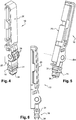
Figures 1 à 3 montrent un exemple de porte-repère selon un aspect de l'invention, dans une position abaissée de sa deuxième partie d'identification. - Les
Figures 4 à 6 montrent le porte-repère desFigures 1 à 3 dans une position relevée de sa deuxième partie d'identification. - Les
Figures 7 et 8 montrent un exemple de bloc de jonction selon un autre aspect de l'invention, le porte-repère desFigures 1 à 6 étant fixé sur le boitier isolant. - Les
Figures 1 à 6 annexées telles que présentées sommairement ci-dessus montrent un exemple de porte-repère individuel 10 selon un aspect de l'invention, destiné à être monté de manière démontable sur un boitier électriquement isolant 12 d'un bloc de jonction 11 électrique également connu sous le nom de « terminal block » en terminologie anglo-saxonne. - Par « individuel », il est compris que le porte-repère 10 est tel qu'il équipe individuellement un seul bloc de jonction 11 et permet d'identifier au moins une fonction destinée à être remplie par le bloc de jonction 11 sur lequel il est fixé. Autrement dit, le porte-repère 10 n'identifie que les fonctions remplies par ce bloc de jonction 11.
- Les
Figures 7 et 8 annexées montrent également un exemple de bloc de jonction 11 électrique selon un autre aspect de l'invention, le porte-repère 10 desFigures 1 à 6 étant fixé sur le boitier isolant 12 d'une manière particulière qui sera décrite plus loin. - En référence aux
Figures 7 et 8 , le bloc de jonction 11 est un appareil électrique comprenant au moins deux bornes de connexion 13 permettant chacune de connecter un conducteur électrique (non représenté) correspondant, par exemple sous la forme d'un fil électriquement conducteur. Le bloc de jonction 11 comprend aussi au moins une barrette de liaison 14 électriquement conductrice pour établir la liaison électrique entre les deux conducteurs électriques connectés aux deux bornes de connexion 13. - La réunion des deux bornes de connexion 13 et de la barrette de liaison 14 constitue un étage. La variante illustrée sur les
Figures 7 et 8 est un bloc de jonction 11 à un seul étage, mais le bloc de jonction 11 pourrait indifféremment comporter deux ou trois étages, en fonction des applications associées au bloc de jonction 11 et en fonction des besoins des utilisateurs. - Comme indiqué précédemment, le bloc de jonction 11 comprend donc le boitier isolant 12 évoqué ci-dessus, dans lequel sont montées les deux bornes de connexion 13 et la (les) barrette(s) de liaison 14 électriquement conductrice(s). Chaque borne de connexion 13 peut être d'une nature quelconque, par exemple utilisant une fixation par vis ou par ressort de contact, ou bien de type auto-dénudant.
- Le boitier isolant 12 possède une face arrière 15 équipée d'éléments de fixation 16 permettant de fixer le bloc de jonction 11 sur un rail de support (non représenté) selon un agencement dans lequel une pluralité de blocs de jonction 11 sont disposés côte à côte sur une même rangée orientée suivant le rail de support. Les éléments de fixation 16 peuvent coopérer avec le rail de support selon un principe d'encliquetage ou d'emboîtement élastique.
- D'ailleurs, un autre aspect de l'invention concerne un agencement comprenant le rail de support et au moins deux blocs de jonction 11 tels que décrits ici, autrement dit une pluralité de tels blocs de jonction 11, fixés par leurs faces arrières de sorte à être disposés côte à côte sur une même rangée orientée selon la direction du rail de support. Il est entendu que le nombre de blocs de jonction 11 peut être supérieur ou égal à 2.
- Pour une bonne compréhension de l'organisation spatiale, un repère orthonormé est associé au boitier isolant 12. La direction X correspond à la direction du boitier isolant 12 qui est orientée dans le sens de la longueur du rail de support lorsque le bloc de jonction 11 est fixé sur le rail de support. La dimension du boitier isolant 12 selon la direction X correspond à son épaisseur. La direction Y correspond à la direction du boitier isolant 12 qui est orientée dans le sens de la largeur du rail de support lorsque le bloc de jonction 11 est fixé sur le rail de support. La dimension du boitier isolant 12 selon la direction Y correspond à sa longueur. La direction Z correspond à la direction du boitier isolant 12 qui est localement perpendiculaire à la paroi où est fixé le rail de support lorsque le bloc de jonction 11 est fixé sur le rail de support. La dimension du boitier isolant 12 selon la direction Z correspond à sa hauteur. La hauteur et la longueur du boitier isolant 12 sont sensiblement égales entre elles tandis que l'épaisseur est nettement inférieure à la hauteur et à la longueur.
- Le boitier isolant 12 comprend également une face avant 17 comprenant au moins un puits de shunt 18. Le nombre de puits de shunt 18 peut être supérieur ou égal à 1, en fonction des applications et des besoins des utilisateurs du bloc de jonction 11. A titre d'exemple non limitatif, la variante illustrée comprend deux puits de shunt 18. Les deux puits de shunt 18 sont décalés l'un par rapport à l'autre suivant la longueur du boitier isolant 11 qui est comptée selon la direction Y. Chaque puits de shunt 18 s'étend suivant la direction Z. Les faces arrière et avant 15, 17 sont opposées suivant la direction Z.
- Le porte-repère 10 comprend une première partie de fixation 19 configurée de sorte à pouvoir être fixée dans la face avant 17 du boitier isolant 12 du bloc de jonction 11. Notamment, la première partie de fixation 19 est configurée de sorte que sa fixation sur la face avant 17 du boitier isolant 12 se pratique par une insertion dans l'un des puits de shunt 18 ménagés dans la face avant 17 du boitier isolant 12 du bloc de jonction 11.
- Le bloc de jonction 11 comprend donc un tel porte-repère 10 dont la première partie de fixation 19 est fixée dans la face avant 17 du boitier isolant 12. Notamment, la première partie de fixation 19 est insérée dans l'un des puits de shunt 18 ménagés dans la face avant 17 du boitier isolant 12.
- Par « puits de shunt », il est entendu une ouverture ménagée dans le boitier isolant 12 de sorte à permettre une communication entre l'intérieur et l'extérieur du boitier isolant 12 et configurée pour permettre la mise en place dans cette ouverture d'un élément de shunt (non représenté), autrement connu sous le nom de cavalier de shunt. L'élément de shunt vient s'insérer dans deux puits de shunt 18 appartenant à deux blocs de jonction 11 adjacents au sein de la rangée de blocs 11 montés sur le rail de support. La mise en place de l'élément de shunt dans les puits de shunt 18 des deux blocs de jonction 11 adjacents permet d'établir un contact électrique entre deux barrettes de liaison 14 implantées respectivement à l'intérieur des boitiers isolants 12 des deux blocs de jonction 11 adjacents.
- Le porte-repère 10 comprend une deuxième partie d'identification 20 articulée par rapport à la première partie de fixation 19. La deuxième partie d'identification 20 peut donc être mobile par pivotement par rapport au boitier isolant 12 lorsque la première partie de fixation 19 est fixée dans le puits de shunt 18 du boitier isolant 12.
- La deuxième partie d'identification 20 comprend au moins une portion d'identification 21. L'axe de pivotement D1 conféré par l'articulation de la deuxième partie d'identification 20 par rapport à la première partie de fixation 19 est situé à une extrémité de la deuxième partie d'identification 20 et est sensiblement aligné avec ladite au moins une portion d'identification 21. Autrement dit, ladite au moins une portion d'identification 21 est décalée par rapport à l'axe de pivotement D1 selon une direction perpendiculaire à la direction de l'axe de pivotement D1. Par « sensiblement aligné », on entend « exactement aligné » ou « aligné dans une tolérance donnée », cette tolérance donnée pouvant être une tolérance angulaire ou une tolérance dimensionnelle comptées dans le plan perpendiculaire à l'axe de pivotement D1. Notamment, l'angle formé, dans le plan perpendiculaire à l'axe de pivotement D1, entre la portion d'identification 21 et la droite rejoignant l'axe D1 et la portion d'identification 21 admet une tolérance angulaire de 20°, en ce sens que cet angle est égal à 180° à 20° près, restant donc inclus dans une plage variant entre 160° et 200°. Alternativement, il peut être admis que, vu dans le plan perpendiculaire à l'axe de pivotement D1, la position de l'axe D1 par rapport à l'orientation générale de la portion d'identification 21 admet une tolérance dimensionnelle de 5 mm, en ce sens que la position de l'axe D1 peut être située exactement le long de l'orientation générale de la portion d'identification 21 ou présenter un décalage vers le haut ou vers le bas par rapport à l'orientation générale de la portion d'identification ayant une valeur incluse dans une plage variant entre 0 et 5 mm.
- La portion d'identification 21 peut présenter une partie sensiblement plane et l'axe de pivotement D1 est agencé sensiblement dans le prolongement de cette partie plane. Autrement dit, l'axe de pivotement D1 est sensiblement contenu dans un plan prolongeant la partie plane de la portion d'identification 21 et est décalé par rapport à la portion d'identification 21 dans ledit plan. Par « sensiblement contenu », on entend les mêmes tolérances que celles décrites dans le paragraphe précédent : en particulier, l'axe de pivotement D1 peut être situé exactement dans le plan prolongeant la partie plane de la portion d'identification 21 ou être décalé vers le haut ou vers le bas, par rapport au plan prolongeant la partie plane de la portion d'identification 21, selon une valeur incluse entre 0 et 5 mm.
- Selon un mode de réalisation, la deuxième partie d'identification 20 comprend un levier allongé s'étendant selon une direction principale d'extension, correspondant à sa direction de plus grande longueur. L'axe de pivotement D1 et ladite au moins une portion d'identification 21 sont décalés l'un par rapport à l'autre selon la direction principale d'extension du levier allongé. L'axe de pivotement D1 est agencé à une extrémité du levier allongé, cette extrémité étant considérée dans la direction principale. Chaque portion d'identification 21 est par exemple ménagée dans une face supérieure 22 du levier allongé. Le mouvement d'articulation de la deuxième partie d'identification 20 correspond à un pivotement du levier allongé autour de l'axe de pivotement D1, la direction principale d'extension du levier allongé présentant donc une orientation variable autour de l'axe de pivotement D1 en même temps que le pivotement du levier allongé.
- Dans un mode de réalisation particulier non limitatif, la deuxième partie d'identification 20 est munie d'une pluralité de portions d'identification 21 alignées entre elles, c'est-à-dire décalées deux à deux le long d'une même et unique direction D2. L'articulation de la deuxième partie d'identification 20 par rapport à la première partie de fixation 19 est sensiblement située dans le prolongement, selon la direction D2, de l'alignement des portions d'identification 21 entre elles. Par « sensiblement situé dans le prolongement », on entend les mêmes tolérances que celles décrites précédemment en lien avec les termes « sensiblement aligné » et « sensiblement contenu ».
- Ainsi, les différentes portions d'identification 21 sont décalées entre elles selon la même direction D2 que la direction suivant laquelle chaque portion d'identification 21 est décalée par rapport à l'axe de pivotement D1.
- Dans l'exemple illustré, la deuxième partie d'identification 20 comprend par exemple deux portions d'identification 21, décalées entre elles le long de la direction principale d'extension du levier allongé. La direction principale d'extension du levier allongé correspond à la direction D2 le long de laquelle les portions d'identification 21 sont échelonnées. Chacune de ces deux portions d'identification 21 est décalée par rapport à l'axe de pivotement D1 suivant la direction principale d'extension du levier allongé, c'est-à-dire également suivant la direction D2.
- Comme cela est illustré, chaque portion d'identification 21 est par exemple configurée pour recevoir un repère d'identification (non représenté). A titre d'exemple, chaque portion d'identification 21 se présente sous la forme d'une fente d'insertion du repère d'identification dans laquelle le repère d'identification est inséré par un mouvement de coulissement perpendiculaire à la direction D2.
- L'axe de pivotement D1 de la deuxième partie d'identification 20 par rapport à la première partie de fixation 19 est perpendiculaire à la direction D3 suivant laquelle la première partie de fixation 19 est destinée à être insérée dans le puits de shunt 18. La direction D3 est orientée parallèlement à la direction Z.
- Dans la variante qui est illustrée, la première partie de fixation 19 et la deuxième partie d'identification 20 sont constituées par deux pièces distinctes assemblées l'une avec l'autre par des éléments de solidarisation à pivotement permettant un pivotement de la deuxième partie d'identification 20 par rapport à la première partie de fixation 19 de sorte à constituer l'articulation entre la première partie de fixation 19 et la deuxième partie d'identification 20. Les éléments de solidarisation à pivotement sont de nature quelconque dès lors qu'ils remplissent la fonction présentée ici.
- Les éléments de solidarisation à pivotement comprennent par exemple une partie tubulaire mâle 23 solidaire d'une extrémité de la première partie de fixation 19, cette extrémité étant considérée suivant la direction D3. L'axe de la partie tubulaire mâle 23 est orienté selon la direction X. Il est inséré suivant la direction Z par emboîtement élastique dans une cavité tubulaire 24 complémentaire, elle-même solidaire d'une extrémité de la deuxième partie d'identification 20, cette extrémité étant considérée suivant la direction D2. L'axe d'orientation de la cavité tubulaire 24 est également orienté suivant la direction X. La coopération entre la partie tubulaire mâle 23 avec la cavité tubulaire 24 constitue une liaison mécanique de type liaison pivot, dont l'axe de pivotement correspond à l'axe de pivotement D1 précité. L'axe de pivotement D1 est donc orienté parallèlement à la direction X.
- Il est toutefois envisageable de prévoir une organisation inversée, en rendant la partie tubulaire mâle 23 solidaire de la deuxième partie d'identification 20 et en rendant la cavité tubulaire 24 solidaire de la première partie de fixation 19.
- Il reste également possible, dans une version alternative à celle décrite ci-dessus, que la première partie de fixation 19 et la deuxième partie d'identification 20 soient formées dans une seule et même pièce monobloc, l'articulation entre la première partie de fixation 19 et la deuxième partie d'identification 20 étant dans ce cas constituée par une zone localement déformable élastiquement de cette pièce monobloc. Cette zone localement déformable peut être obtenue par une modification locale de matière et/ou par une réduction locale d'une dimension adoptée par la matière. La capacité de déformation élastique résultera d'un compromis entre la facilité de pivotement et la résistance mécanique évitant une rupture de cette zone sous charge.
- L'axe de pivotement D1 de la deuxième partie d'identification 20 par rapport à la première partie de fixation 19 est également perpendiculaire à la direction D2 suivant laquelle les portions d'identification 21 sont échelonnées le long de la deuxième partie d'identification 20. La direction D2 est mobile par rotation dans le plan (Y, Z).
- Par le montage décrit précédemment, la deuxième partie d'identification 20 varie avantageusement au moins entre une position angulaire abaissée (
Figure 7 ) par rapport au boitier isolant 12 dans laquelle la deuxième partie d'identification 20 est sensiblement parallèle à la face avant 17 du boitier isolant 12 et une position angulaire redressée (Figure 8 ) dans laquelle la deuxième partie d'identification 20 est sensiblement perpendiculaire localement à la face avant 17 du boitier isolant 12. La première partie de fixation 19 du porte-repère 10 est immobile par rapport au boitier isolant 12 durant le changement de position angulaire de la deuxième partie d'identification 20 du porte-repère 10. LesFigures 1 à 3 montrent la position occupée par la deuxième partie d'identification 20 par rapport à la première partie de fixation 19 lorsque la deuxième partie d'identification 20 est apte à occuper sa position angulaire abaissée. A l'inverse, lesFigures 4 à 6 montrent la position occupée par la deuxième partie d'identification 20 par rapport à la première partie de fixation 19 lorsque la deuxième partie d'identification 20 est apte à occuper sa position angulaire redressée. La position angulaire redressée est adoptée par la deuxième partie d'identification 20 lorsque l'accès aux ouvertures 29 qui donnent accès aux bornes de connexion 13 et dans lesquelles les conducteurs électriques sont insérés est nécessaire et/ou lorsque l'accès à l'autre puits de shunt 18 est nécessaire. Sinon, pour une facilité de lecture des données inscrites au niveau des portions d'identification et pour une diminution de l'encombrement, la position angulaire abaissée est normalement adoptée par la deuxième partie d'identification 20. - Dans un mode de réalisation particulier, le porte-repère 10 comprend des éléments d'indexation angulaire de la position angulaire occupée par la deuxième partie d'identification 20 par rapport à la première partie de fixation 19, notamment selon des positions angulaires prédéterminées. Les éléments d'indexation angulaire sont par exemple constitués pour prédéterminer uniquement la position angulaire abaissée et la position angulaire relevée que la deuxième partie d'identification peut sélectivement occuper. Les éléments d'indexation angulaire peuvent également être conçus pour éventuellement prédéterminer une ou plusieurs position(s) angulaire(s) intermédiaire(s) entre les positions angulaires abaissée et redressée.
- Les éléments d'indexation angulaire sont par exemple obtenus par des butées angulaires 25, 26 solidaires de la deuxième partie d'identification, agencées de sorte à limiter et borner la course angulaire maximale de la deuxième partie d'identification 20 autour de l'axe de pivotement D1. La butée 25 est utilisée (
Figure 8 ) pour limiter et prédéterminer la position angulaire redressée de la deuxième partie d'identification 20. La butée 26 est au contraire utilisée (Figure 7 ) pour limiter et prédéterminer la position angulaire abaissée de la deuxième partie d'identification 20. Alternativement ou de manière combinée, les éléments d'indexation angulaire peuvent également comprendre une pluralité de fentes 27 ménagées sur la partie tubulaire mâle 23 et un ergot 28 solidaire de la cavité tubulaire 24 apte à venir s'insérer, dans chacune des positions prédéterminées souhaitées pour la deuxième partie d'identification 20, dans l'une correspondante des fentes 27 parmi la pluralité de fentes 27. - Selon un mode de réalisation particulier, la première partie de fixation 19 présente une symétrie selon un plan contenant à la fois la direction D3 selon laquelle la première partie de fixation 19 est destinée à être insérée dans le puits de shunt 18 et la direction correspondant à l'axe de pivotement D1 autour duquel la deuxième partie d'identification 20 est articulée par rapport à la première partie de fixation 19. Cette symétrie est organisée de sorte que le porte-repère 10 puisse occuper deux configurations différentes par rapport au boitier isolant 12, ces deux configurations variant l'une de l'autre par une rotation de 180 degrés de la première partie de fixation 19 autour de la direction D3 d'insertion dans le puits de shunt 18. Pour bien comprendre, le porte-repère 10 peut soit occuper la position représentée sur les
Figures 7 et 8 , soit une configuration inversée dans laquelle le porte-repère 10 serait retourné à 180° autour de la direction D3, prenant alors une position symétrique par rapport au plan (D1, D3), i.e. par rapport à un plan (X, Z) passant par D3. Lorsque le bloc de jonction 11 est fixé sur le rail de support, il est alors avantageusement possible de choisir l'orientation occupée par la deuxième partie d'identification 20 en position abaissée. Dans l'une des configurations angulaires que peut prendre la première partie de fixation 19 autour de la direction D3, la deuxième partie d'identification 20 occupant sa position abaissée s'étend vers le bas selon la direction Y. Dans l'autre des configurations angulaires que peut prendre la première partie de fixation 19 autour de la direction D3, la deuxième partie d'identification 20 occupant sa position abaissée s'étend vers le haut selon la direction Y. - Le système d'insertion de la première partie de fixation 19 dans tout puits de shunt 18 du boitier isolant peut être de nature et de conception quelconques.
- Notamment, le puits de shunt 18 peut comprendre une nervure annulaire interne 30 aménagée au niveau de son embouchure vers la face avant 17 et comprise dans un plan perpendiculaire à la direction D3 suivant laquelle la première partie de fixation 19 est insérée dans ce puits de shunt 18. La première partie de fixation 19 comprend une gorge annulaire externe 31 dans laquelle la nervure annulaire interne 30 du puits de shunt 18 vient s'insérer par emboîtement élastique durant l'insertion de la première partie de fixation 19.
- Le puits de shunt 18 peut comprendre également un épaulement annulaire interne 32 se prolongeant par un alésage de réception 33 du côté opposé à l'embouchure du puits de shunt 18 sur la face avant 17 du boitier isolant 12. La première partie de fixation 19 comprend un tenon d'extrémité 34 élastiquement déformable venant s'insérer dans l'alésage de réception 33 durant l'insertion de la première partie de fixation 19 moyennant une déformation élastique du tenon d'extrémité 34. La déformation élastique du tenon d'extrémité 34 permet de compenser les variations de diamètre de l'alésage de réception 33 susceptibles d'apparaître entre deux blocs de jonction 11 différents. De plus, la déformation élastique du tenon d'extrémité 34 supprime le porte-à-faux subi par le porte-repère 10 dans les différentes positions angulaires de la deuxième partie d'identification 20.
- Avantageusement, la largeur de la deuxième partie de fixation 20 comptée suivant la direction suivant laquelle l'axe de pivotement D1 de la deuxième partie de fixation 20 par rapport à la première partie de fixation 19 est comptée est égale ou inférieure à l'épaisseur du boitier isolant 12 du bloc de jonction 11 comptée suivant la direction X suivant laquelle le rail de support est orienté lorsque le bloc de jonction 11 est fixé sur le rail de support.
- Au sein de l'agencement comprenant au moins deux blocs de jonction 11 positionnés côte-à-côte, le porte-repère 10 fixé dans la face avant 17 du boitier isolant 12 de l'un des blocs de jonction 11 est indépendant du porte-repère 10 fixé dans la face avant 17 du boitier isolant 12 de l'autre des blocs de jonction 11. Notamment, le porte-repère 11 fixé dans le puits de shunt 18 du boitier isolant 12 de l'un des blocs de jonction 11 est indépendant du porte-repère 10 fixé dans le puits de shunt 18 du boitier isolant 12 de l'autre des blocs de jonction 11. Cette indépendance se traduit par une possibilité de mouvement angulaire de la deuxième partie d'identification 20 et une possibilité de retrait de la première partie de fixation 19 hors du boitier isolant 12 indépendantes d'un porte-repère 10 à l'autre porte-repère 10.
- De ce qui précède, il résulte que le porte-repère 10, le bloc de jonction 11 et l'agencement qui viennent d'être décrits proposent avantageusement une solution simple, économique, pratique et sécuritaire, efficace et peu encombrante.
- Bien entendu, l'invention n'est évidemment pas limitée aux modes de réalisation représentés et décrits ci-avant, mais en couvre au contraire toutes les variantes.
Claims (12)
- Bloc de jonction (11) électrique comprenant un boitier isolant (12) ayant une face arrière (15) équipée d'éléments de fixation (16) permettant de fixer le bloc de jonction (11) sur un rail de support selon un agencement dans lequel une pluralité de blocs de jonction (11) sont disposés côte à côte sur une même rangée orientée suivant la direction du rail de support et une face avant (17) comprenant au moins un puits de shunt (18), le bloc de jonction (11) comprenant un porte-repère (10) comprenant une première partie de fixation (19) insérée dans le puits de shunt (18) et une deuxième partie d'identification (20) ayant au moins une portion d'identification (21), caractérisé en ce que la deuxième partie d'identification (21) est articulée par rapport à la première partie de fixation (19) de sorte à être mobile par pivotement par rapport au boitier isolant (12) et varie au moins entre une position angulaire abaissée par rapport au boitier isolant (12) dans laquelle la deuxième partie d'identification (20) est sensiblement parallèle à la face avant (17) du boitier isolant (12) et une position angulaire redressée dans laquelle la deuxième partie d'identification (20) est sensiblement perpendiculaire localement à la face avant (17) du boitier isolant (12), la première partie de fixation (19) du porte-repère (10) étant immobile par rapport au boitier isolant (12) durant le changement de position angulaire de la deuxième partie d'identification (20) du porte-repère (10).
- Bloc de jonction (11) selon la revendication 1, caractérisé en ce que la première partie de fixation (19) présente une symétrie selon un plan contenant à la fois la direction (D3) selon laquelle la première partie de fixation (19) est destinée à être insérée dans le puits de shunt (18) et la direction correspondant à l'axe de pivotement (D1) autour duquel la deuxième partie d'identification (20) est articulée par rapport à la première partie de fixation (19), de sorte que le porte-repère (10) peut occuper deux configurations différentes par rapport au boitier isolant (12) variant l'une de l'autre par une rotation de 180 degrés de la première partie de fixation (19) autour de la direction (D3) d'insertion dans le puits de shunt (18).
- Bloc de jonction (11) selon l'une des revendications 1 ou 2, caractérisé en ce que le porte-repère (10) comprend des éléments d'indexation angulaire (25, 26, 27, 28) de la position angulaire occupée par la deuxième partie d'identification (20) par rapport à la première partie de fixation (19), notamment selon des positions angulaires prédéterminées.
- Bloc de jonction (11) selon l'une des revendications 1 à 3, caractérisé en ce que la deuxième partie d'identification (20) est munie d'une pluralité de portions d'identification (21) alignées entre elles, notamment permettant chacune la réception d'un repère d'identification.
- Bloc de jonction (11) selon la revendication 4, caractérisé en ce que l'axe de pivotement (D1) de la deuxième partie d'identification (20) par rapport à la première partie de fixation (19) est perpendiculaire à la direction (D3) suivant laquelle la première partie de fixation (19) est insérée dans le puits de shunt (18) et perpendiculaire à la direction (D2) suivant laquelle les portions d'identification (21) sont échelonnées le long de la deuxième partie d'identification (20).
- Bloc de jonction (11) selon l'une des revendications 1 à 5, caractérisé en ce que la première partie de fixation (19) et la deuxième partie d'identification (20) sont formées dans une seule et même pièce monobloc, l'articulation entre la première partie de fixation (19) et la deuxième partie d'identification (20) étant constituée par une zone localement déformable élastiquement de ladite pièce monobloc.
- Bloc de jonction (11) selon l'une des revendications 1 à 5, caractérisé en ce que la première partie de fixation (19) et la deuxième partie d'identification (20) sont constituées par deux pièces distinctes assemblées l'une avec l'autre par des éléments de solidarisation à pivotement (23, 24) permettant un pivotement de la deuxième partie d'identification (20) par rapport à la première partie de fixation (19) de sorte à constituer l'articulation entre la première partie de fixation (19) et la deuxième partie d'identification (20).
- Bloc de jonction (11) selon l'une des revendications 1 à 7, caractérisé en ce que l'axe de pivotement (D1) conféré par l'articulation de la deuxième partie d'identification (20) par rapport à la première partie de fixation (19) est situé à une extrémité de la deuxième partie d'identification (20) et est sensiblement aligné avec ladite au moins une portion d'identification (21).
- Bloc de jonction (11) selon l'une des revendications 1 à 8, caractérisé en ce que le puits de shunt (18) comprend une nervure annulaire interne (30) aménagée au niveau de son embouchure vers la face avant (17) et comprise dans un plan perpendiculaire à la direction (D3) suivant laquelle la première partie de fixation (19) est insérée dans le puits de shunt (18) et en ce que la première partie de fixation (19) comprend une gorge annulaire externe (31) dans laquelle la nervure annulaire interne (30) du puits de shunt (18) vient s'insérer par emboîtement élastique durant l'insertion de la première partie de fixation (19).
- Bloc de jonction (11) selon l'une des revendications 1 à 9, caractérisé en ce que le puits de shunt (18) comprend un épaulement annulaire interne (32) se prolongeant par un alésage de réception (33) du côté opposé à l'embouchure du puits de shunt (18) sur la face avant (17) du boitier isolant (12) et en ce que la première partie de fixation (19) comprend un tenon d'extrémité (34) élastiquement déformable venant s'insérer dans l'alésage de réception (33) durant l'insertion de la première partie de fixation (19) moyennant une déformation élastique du tenon d'extrémité (34).
- Bloc de jonction (11) selon l'une des revendications 1 à 10, caractérisé en ce que la largeur de la deuxième partie de fixation (20) comptée suivant la direction suivant laquelle l'axe de pivotement (D1) de la deuxième partie de fixation (20) par rapport à la première partie de fixation (19) est comptée est égale ou inférieure à l'épaisseur du boitier isolant (12) du bloc de jonction (11) comptée suivant la direction (X) suivant laquelle le rail de support est orienté lorsque le bloc de jonction (11) est fixé sur le rail de support.
- Agencement comprenant un rail de support et au moins deux blocs de jonction (11), chacun étant un bloc de jonction (11) selon l'une quelconque des revendications 1 à 11, fixés par leurs faces arrières (15) de sorte à être disposés côte à côte sur une même rangée orientée selon la direction du rail de support, agencement dans lequel le porte-repère (10) fixé dans le puits de shunt (18) du boitier isolant (12) de l'un des blocs de jonction (11) est indépendant du porte-repère (10) fixé dans le puits de shunt (18) du boitier isolant (12) de l'autre des blocs de jonction (11).
Priority Applications (1)
| Application Number | Priority Date | Filing Date | Title |
|---|---|---|---|
| EP16169285.0A EP3244489B1 (fr) | 2016-05-12 | 2016-05-12 | Bloc de jonction avec porte-repère apte à être fixé dans un puits de shunt |
Applications Claiming Priority (1)
| Application Number | Priority Date | Filing Date | Title |
|---|---|---|---|
| EP16169285.0A EP3244489B1 (fr) | 2016-05-12 | 2016-05-12 | Bloc de jonction avec porte-repère apte à être fixé dans un puits de shunt |
Publications (2)
| Publication Number | Publication Date |
|---|---|
| EP3244489A1 EP3244489A1 (fr) | 2017-11-15 |
| EP3244489B1 true EP3244489B1 (fr) | 2020-12-16 |
Family
ID=55968976
Family Applications (1)
| Application Number | Title | Priority Date | Filing Date |
|---|---|---|---|
| EP16169285.0A Active EP3244489B1 (fr) | 2016-05-12 | 2016-05-12 | Bloc de jonction avec porte-repère apte à être fixé dans un puits de shunt |
Country Status (1)
| Country | Link |
|---|---|
| EP (1) | EP3244489B1 (fr) |
Families Citing this family (2)
| Publication number | Priority date | Publication date | Assignee | Title |
|---|---|---|---|---|
| DE102021106498A1 (de) | 2021-03-17 | 2022-09-22 | Weidmüller Interface GmbH & Co. KG | Anordnung eines Reihenklemmblocks mit Zubehörhalter |
| DE202022100453U1 (de) * | 2022-01-26 | 2023-05-04 | WAGO Verwaltungsgesellschaft mit beschränkter Haftung | Set aus einer Leiteranschlussklemme und einem Zubehörelement |
Family Cites Families (6)
| Publication number | Priority date | Publication date | Assignee | Title |
|---|---|---|---|---|
| GB1380533A (en) * | 1973-04-24 | 1975-01-15 | Hego Electric Gmbh | Electrical connector with insulating separator |
| DE2914192C2 (de) * | 1979-04-07 | 1982-04-29 | F. Wieland, Elektrische Industrie GmbH, 8600 Bamberg | Schaltanlagenreihenklemme mit zugeordneter Isolier-Trennwand |
| FR2757316B1 (fr) * | 1996-12-16 | 1999-01-22 | Entrelec Sa | Module de raccordement a bornes de connexion interconnectables par piece(s) conductrice(s) mobile(s) |
| DE202008013609U1 (de) | 2008-06-27 | 2009-11-19 | Weidmüller Interface GmbH & Co. KG | Aus mehreren Kennzeichnungsvorrichtungen zusammenstellbare Kennzeichnungs-Reihenanordnung |
| DE202009003250U1 (de) | 2009-03-06 | 2010-07-22 | Weidmüller Interface GmbH & Co. KG | Aus mehreren Kennzeichnungsvorrichtungen zusammenstellbare Kennzeichnungs-Reihenanordnung |
| WO2012041778A1 (fr) * | 2010-09-30 | 2012-04-05 | Weidmüller Interface GmbH & Co. KG | Connecteur transversal à marquage |
-
2016
- 2016-05-12 EP EP16169285.0A patent/EP3244489B1/fr active Active
Non-Patent Citations (1)
| Title |
|---|
| None * |
Also Published As
| Publication number | Publication date |
|---|---|
| EP3244489A1 (fr) | 2017-11-15 |
Similar Documents
| Publication | Publication Date | Title |
|---|---|---|
| FR2550014A1 (fr) | Monture de pile electrique, pour piles plates | |
| EP1028490A1 (fr) | Raccord coaxial pour relier deux cartes de circuit imprimé | |
| EP3323171B1 (fr) | Isolateur pour une connexion électrique pivotable | |
| EP2286492B1 (fr) | Dispositif de porte-balai et son application a la realisation d'un demarreur pour vehicule automobile | |
| FR2875957A1 (fr) | Dispositif de verrouillage d'elements de connecteur et connecteur le comprenant | |
| EP3244489A1 (fr) | Porte-repère apte à être fixé dans un puits de shunt d'un bloc de jonction | |
| EP2584657B1 (fr) | Système de détrompage pour connecteur et procédé de montage de ce système sur un connecteur | |
| CA3088062A1 (fr) | Socle de prise equipe d'un disque et d'un obturateur | |
| FR2717625A1 (fr) | Boîtier pour lecteur de carte à microcircuit. | |
| EP0682387A1 (fr) | Embase de connexion à une fiche complémentaire | |
| EP1318569B1 (fr) | Socle de prise de courant à obturateur d'alvéoles et gamme comprenant un tel socle | |
| FR3025947A1 (fr) | Corps isolant pour connecteur debrochable | |
| EP3300530B1 (fr) | Ensemble de boîtiers d'appareils electriques mecaniquement et electriquement relies entre eux | |
| EP0975057B1 (fr) | "Piece de contact pour connecteur femelle, et connecteur comportant une telle piece de contact" | |
| EP4331327B1 (fr) | Ensemble électronique modulaire | |
| FR2540670A3 (fr) | Appareil electrique muni d'au moins une cartouche coupe-circuit | |
| EP0274948A1 (fr) | Connecteur par déplacement d'isolant pour câble monoconducteur | |
| EP0593343B1 (fr) | Connecteur électrique à éléments de contact hermaphrodites | |
| EP3291376A1 (fr) | Bornier de connexion électrique et système de double interrupteur comprenant deux tels borniers | |
| EP2469672B1 (fr) | Dispositif de fixation d'un module de raccordement électrique par encliquetage sur un rail ou un support percé | |
| EP3312948B1 (fr) | Prise electrique comprenant une piece monobloc de support et de reception d'alveoles et procede d'assemblage d'une telle prise electrique | |
| EP3349306B1 (fr) | Appareil électrique modulaire | |
| CA2570644C (fr) | Systeme de connexion automatique de deux circuits electriques d'un vehicule | |
| EP1542321A1 (fr) | Appareil électrique en deux portions emboítables comportant des moyens de détrompage | |
| FR2544120A1 (fr) | Capsule de memoire pour un systeme d'ordinateur |
Legal Events
| Date | Code | Title | Description |
|---|---|---|---|
| PUAI | Public reference made under article 153(3) epc to a published international application that has entered the european phase |
Free format text: ORIGINAL CODE: 0009012 |
|
| STAA | Information on the status of an ep patent application or granted ep patent |
Free format text: STATUS: THE APPLICATION HAS BEEN PUBLISHED |
|
| AK | Designated contracting states |
Kind code of ref document: A1 Designated state(s): AL AT BE BG CH CY CZ DE DK EE ES FI FR GB GR HR HU IE IS IT LI LT LU LV MC MK MT NL NO PL PT RO RS SE SI SK SM TR |
|
| AX | Request for extension of the european patent |
Extension state: BA ME |
|
| STAA | Information on the status of an ep patent application or granted ep patent |
Free format text: STATUS: REQUEST FOR EXAMINATION WAS MADE |
|
| 17P | Request for examination filed |
Effective date: 20180515 |
|
| RBV | Designated contracting states (corrected) |
Designated state(s): AL AT BE BG CH CY CZ DE DK EE ES FI FR GB GR HR HU IE IS IT LI LT LU LV MC MK MT NL NO PL PT RO RS SE SI SK SM TR |
|
| STAA | Information on the status of an ep patent application or granted ep patent |
Free format text: STATUS: EXAMINATION IS IN PROGRESS |
|
| 17Q | First examination report despatched |
Effective date: 20190110 |
|
| RAP1 | Party data changed (applicant data changed or rights of an application transferred) |
Owner name: TYCO ELECTRONICS SERVICES GMBH |
|
| RAP1 | Party data changed (applicant data changed or rights of an application transferred) |
Owner name: TE CONNECTIVITY SERVICES GMBH |
|
| GRAP | Despatch of communication of intention to grant a patent |
Free format text: ORIGINAL CODE: EPIDOSNIGR1 |
|
| STAA | Information on the status of an ep patent application or granted ep patent |
Free format text: STATUS: GRANT OF PATENT IS INTENDED |
|
| RIC1 | Information provided on ipc code assigned before grant |
Ipc: H01R 9/24 20060101AFI20200820BHEP Ipc: H01R 9/26 20060101ALN20200820BHEP |
|
| INTG | Intention to grant announced |
Effective date: 20200914 |
|
| GRAS | Grant fee paid |
Free format text: ORIGINAL CODE: EPIDOSNIGR3 |
|
| GRAA | (expected) grant |
Free format text: ORIGINAL CODE: 0009210 |
|
| STAA | Information on the status of an ep patent application or granted ep patent |
Free format text: STATUS: THE PATENT HAS BEEN GRANTED |
|
| RAP1 | Party data changed (applicant data changed or rights of an application transferred) |
Owner name: TE CONNECTIVITY SERVICES GMBH |
|
| AK | Designated contracting states |
Kind code of ref document: B1 Designated state(s): AL AT BE BG CH CY CZ DE DK EE ES FI FR GB GR HR HU IE IS IT LI LT LU LV MC MK MT NL NO PL PT RO RS SE SI SK SM TR |
|
| REG | Reference to a national code |
Ref country code: GB Ref legal event code: FG4D Free format text: NOT ENGLISH |
|
| REG | Reference to a national code |
Ref country code: IE Ref legal event code: FG4D Free format text: LANGUAGE OF EP DOCUMENT: FRENCH |
|
| REG | Reference to a national code |
Ref country code: DE Ref legal event code: R096 Ref document number: 602016049746 Country of ref document: DE |
|
| REG | Reference to a national code |
Ref country code: AT Ref legal event code: REF Ref document number: 1346447 Country of ref document: AT Kind code of ref document: T Effective date: 20210115 |
|
| PG25 | Lapsed in a contracting state [announced via postgrant information from national office to epo] |
Ref country code: RS Free format text: LAPSE BECAUSE OF FAILURE TO SUBMIT A TRANSLATION OF THE DESCRIPTION OR TO PAY THE FEE WITHIN THE PRESCRIBED TIME-LIMIT Effective date: 20201216 Ref country code: NO Free format text: LAPSE BECAUSE OF FAILURE TO SUBMIT A TRANSLATION OF THE DESCRIPTION OR TO PAY THE FEE WITHIN THE PRESCRIBED TIME-LIMIT Effective date: 20210316 Ref country code: GR Free format text: LAPSE BECAUSE OF FAILURE TO SUBMIT A TRANSLATION OF THE DESCRIPTION OR TO PAY THE FEE WITHIN THE PRESCRIBED TIME-LIMIT Effective date: 20210317 Ref country code: FI Free format text: LAPSE BECAUSE OF FAILURE TO SUBMIT A TRANSLATION OF THE DESCRIPTION OR TO PAY THE FEE WITHIN THE PRESCRIBED TIME-LIMIT Effective date: 20201216 |
|
| REG | Reference to a national code |
Ref country code: AT Ref legal event code: MK05 Ref document number: 1346447 Country of ref document: AT Kind code of ref document: T Effective date: 20201216 |
|
| REG | Reference to a national code |
Ref country code: NL Ref legal event code: MP Effective date: 20201216 |
|
| PG25 | Lapsed in a contracting state [announced via postgrant information from national office to epo] |
Ref country code: SE Free format text: LAPSE BECAUSE OF FAILURE TO SUBMIT A TRANSLATION OF THE DESCRIPTION OR TO PAY THE FEE WITHIN THE PRESCRIBED TIME-LIMIT Effective date: 20201216 Ref country code: LV Free format text: LAPSE BECAUSE OF FAILURE TO SUBMIT A TRANSLATION OF THE DESCRIPTION OR TO PAY THE FEE WITHIN THE PRESCRIBED TIME-LIMIT Effective date: 20201216 Ref country code: BG Free format text: LAPSE BECAUSE OF FAILURE TO SUBMIT A TRANSLATION OF THE DESCRIPTION OR TO PAY THE FEE WITHIN THE PRESCRIBED TIME-LIMIT Effective date: 20210316 |
|
| PG25 | Lapsed in a contracting state [announced via postgrant information from national office to epo] |
Ref country code: NL Free format text: LAPSE BECAUSE OF FAILURE TO SUBMIT A TRANSLATION OF THE DESCRIPTION OR TO PAY THE FEE WITHIN THE PRESCRIBED TIME-LIMIT Effective date: 20201216 Ref country code: HR Free format text: LAPSE BECAUSE OF FAILURE TO SUBMIT A TRANSLATION OF THE DESCRIPTION OR TO PAY THE FEE WITHIN THE PRESCRIBED TIME-LIMIT Effective date: 20201216 |
|
| REG | Reference to a national code |
Ref country code: LT Ref legal event code: MG9D |
|
| PG25 | Lapsed in a contracting state [announced via postgrant information from national office to epo] |
Ref country code: EE Free format text: LAPSE BECAUSE OF FAILURE TO SUBMIT A TRANSLATION OF THE DESCRIPTION OR TO PAY THE FEE WITHIN THE PRESCRIBED TIME-LIMIT Effective date: 20201216 Ref country code: CZ Free format text: LAPSE BECAUSE OF FAILURE TO SUBMIT A TRANSLATION OF THE DESCRIPTION OR TO PAY THE FEE WITHIN THE PRESCRIBED TIME-LIMIT Effective date: 20201216 Ref country code: LT Free format text: LAPSE BECAUSE OF FAILURE TO SUBMIT A TRANSLATION OF THE DESCRIPTION OR TO PAY THE FEE WITHIN THE PRESCRIBED TIME-LIMIT Effective date: 20201216 Ref country code: SM Free format text: LAPSE BECAUSE OF FAILURE TO SUBMIT A TRANSLATION OF THE DESCRIPTION OR TO PAY THE FEE WITHIN THE PRESCRIBED TIME-LIMIT Effective date: 20201216 Ref country code: PT Free format text: LAPSE BECAUSE OF FAILURE TO SUBMIT A TRANSLATION OF THE DESCRIPTION OR TO PAY THE FEE WITHIN THE PRESCRIBED TIME-LIMIT Effective date: 20210416 Ref country code: RO Free format text: LAPSE BECAUSE OF FAILURE TO SUBMIT A TRANSLATION OF THE DESCRIPTION OR TO PAY THE FEE WITHIN THE PRESCRIBED TIME-LIMIT Effective date: 20201216 Ref country code: SK Free format text: LAPSE BECAUSE OF FAILURE TO SUBMIT A TRANSLATION OF THE DESCRIPTION OR TO PAY THE FEE WITHIN THE PRESCRIBED TIME-LIMIT Effective date: 20201216 |
|
| PG25 | Lapsed in a contracting state [announced via postgrant information from national office to epo] |
Ref country code: AT Free format text: LAPSE BECAUSE OF FAILURE TO SUBMIT A TRANSLATION OF THE DESCRIPTION OR TO PAY THE FEE WITHIN THE PRESCRIBED TIME-LIMIT Effective date: 20201216 Ref country code: PL Free format text: LAPSE BECAUSE OF FAILURE TO SUBMIT A TRANSLATION OF THE DESCRIPTION OR TO PAY THE FEE WITHIN THE PRESCRIBED TIME-LIMIT Effective date: 20201216 |
|
| REG | Reference to a national code |
Ref country code: DE Ref legal event code: R097 Ref document number: 602016049746 Country of ref document: DE |
|
| PG25 | Lapsed in a contracting state [announced via postgrant information from national office to epo] |
Ref country code: IS Free format text: LAPSE BECAUSE OF FAILURE TO SUBMIT A TRANSLATION OF THE DESCRIPTION OR TO PAY THE FEE WITHIN THE PRESCRIBED TIME-LIMIT Effective date: 20210416 |
|
| PLBE | No opposition filed within time limit |
Free format text: ORIGINAL CODE: 0009261 |
|
| STAA | Information on the status of an ep patent application or granted ep patent |
Free format text: STATUS: NO OPPOSITION FILED WITHIN TIME LIMIT |
|
| PG25 | Lapsed in a contracting state [announced via postgrant information from national office to epo] |
Ref country code: IT Free format text: LAPSE BECAUSE OF FAILURE TO SUBMIT A TRANSLATION OF THE DESCRIPTION OR TO PAY THE FEE WITHIN THE PRESCRIBED TIME-LIMIT Effective date: 20201216 Ref country code: AL Free format text: LAPSE BECAUSE OF FAILURE TO SUBMIT A TRANSLATION OF THE DESCRIPTION OR TO PAY THE FEE WITHIN THE PRESCRIBED TIME-LIMIT Effective date: 20201216 |
|
| 26N | No opposition filed |
Effective date: 20210917 |
|
| PG25 | Lapsed in a contracting state [announced via postgrant information from national office to epo] |
Ref country code: DK Free format text: LAPSE BECAUSE OF FAILURE TO SUBMIT A TRANSLATION OF THE DESCRIPTION OR TO PAY THE FEE WITHIN THE PRESCRIBED TIME-LIMIT Effective date: 20201216 |
|
| REG | Reference to a national code |
Ref country code: CH Ref legal event code: PL |
|
| PG25 | Lapsed in a contracting state [announced via postgrant information from national office to epo] |
Ref country code: CH Free format text: LAPSE BECAUSE OF NON-PAYMENT OF DUE FEES Effective date: 20210531 Ref country code: MC Free format text: LAPSE BECAUSE OF FAILURE TO SUBMIT A TRANSLATION OF THE DESCRIPTION OR TO PAY THE FEE WITHIN THE PRESCRIBED TIME-LIMIT Effective date: 20201216 Ref country code: LI Free format text: LAPSE BECAUSE OF NON-PAYMENT OF DUE FEES Effective date: 20210531 Ref country code: LU Free format text: LAPSE BECAUSE OF NON-PAYMENT OF DUE FEES Effective date: 20210512 Ref country code: ES Free format text: LAPSE BECAUSE OF FAILURE TO SUBMIT A TRANSLATION OF THE DESCRIPTION OR TO PAY THE FEE WITHIN THE PRESCRIBED TIME-LIMIT Effective date: 20201216 |
|
| REG | Reference to a national code |
Ref country code: BE Ref legal event code: MM Effective date: 20210531 |
|
| PG25 | Lapsed in a contracting state [announced via postgrant information from national office to epo] |
Ref country code: SI Free format text: LAPSE BECAUSE OF FAILURE TO SUBMIT A TRANSLATION OF THE DESCRIPTION OR TO PAY THE FEE WITHIN THE PRESCRIBED TIME-LIMIT Effective date: 20201216 |
|
| PG25 | Lapsed in a contracting state [announced via postgrant information from national office to epo] |
Ref country code: IE Free format text: LAPSE BECAUSE OF NON-PAYMENT OF DUE FEES Effective date: 20210512 |
|
| PG25 | Lapsed in a contracting state [announced via postgrant information from national office to epo] |
Ref country code: IS Free format text: LAPSE BECAUSE OF FAILURE TO SUBMIT A TRANSLATION OF THE DESCRIPTION OR TO PAY THE FEE WITHIN THE PRESCRIBED TIME-LIMIT Effective date: 20210416 |
|
| PG25 | Lapsed in a contracting state [announced via postgrant information from national office to epo] |
Ref country code: BE Free format text: LAPSE BECAUSE OF NON-PAYMENT OF DUE FEES Effective date: 20210531 |
|
| PG25 | Lapsed in a contracting state [announced via postgrant information from national office to epo] |
Ref country code: HU Free format text: LAPSE BECAUSE OF FAILURE TO SUBMIT A TRANSLATION OF THE DESCRIPTION OR TO PAY THE FEE WITHIN THE PRESCRIBED TIME-LIMIT; INVALID AB INITIO Effective date: 20160512 |
|
| PG25 | Lapsed in a contracting state [announced via postgrant information from national office to epo] |
Ref country code: CY Free format text: LAPSE BECAUSE OF FAILURE TO SUBMIT A TRANSLATION OF THE DESCRIPTION OR TO PAY THE FEE WITHIN THE PRESCRIBED TIME-LIMIT Effective date: 20201216 |
|
| PG25 | Lapsed in a contracting state [announced via postgrant information from national office to epo] |
Ref country code: MK Free format text: LAPSE BECAUSE OF FAILURE TO SUBMIT A TRANSLATION OF THE DESCRIPTION OR TO PAY THE FEE WITHIN THE PRESCRIBED TIME-LIMIT Effective date: 20201216 |
|
| PG25 | Lapsed in a contracting state [announced via postgrant information from national office to epo] |
Ref country code: TR Free format text: LAPSE BECAUSE OF FAILURE TO SUBMIT A TRANSLATION OF THE DESCRIPTION OR TO PAY THE FEE WITHIN THE PRESCRIBED TIME-LIMIT Effective date: 20201216 |
|
| PG25 | Lapsed in a contracting state [announced via postgrant information from national office to epo] |
Ref country code: MT Free format text: LAPSE BECAUSE OF FAILURE TO SUBMIT A TRANSLATION OF THE DESCRIPTION OR TO PAY THE FEE WITHIN THE PRESCRIBED TIME-LIMIT Effective date: 20201216 |
|
| PGFP | Annual fee paid to national office [announced via postgrant information from national office to epo] |
Ref country code: DE Payment date: 20250319 Year of fee payment: 10 |
|
| REG | Reference to a national code |
Ref country code: GB Ref legal event code: 732E Free format text: REGISTERED BETWEEN 20250731 AND 20250806 |
|
| PGFP | Annual fee paid to national office [announced via postgrant information from national office to epo] |
Ref country code: GB Payment date: 20260313 Year of fee payment: 11 |
|
| PGFP | Annual fee paid to national office [announced via postgrant information from national office to epo] |
Ref country code: FR Payment date: 20260309 Year of fee payment: 11 |