EP3244274B1 - Elektrisches gerät mit einer funktionseinrichtung - Google Patents
Elektrisches gerät mit einer funktionseinrichtung Download PDFInfo
- Publication number
- EP3244274B1 EP3244274B1 EP17165854.5A EP17165854A EP3244274B1 EP 3244274 B1 EP3244274 B1 EP 3244274B1 EP 17165854 A EP17165854 A EP 17165854A EP 3244274 B1 EP3244274 B1 EP 3244274B1
- Authority
- EP
- European Patent Office
- Prior art keywords
- function block
- insecure
- signal
- secure
- unit
- Prior art date
- Legal status (The legal status is an assumption and is not a legal conclusion. Google has not performed a legal analysis and makes no representation as to the accuracy of the status listed.)
- Active
Links
Images

Classifications
-
- G—PHYSICS
- G05—CONTROLLING; REGULATING
- G05B—CONTROL OR REGULATING SYSTEMS IN GENERAL; FUNCTIONAL ELEMENTS OF SUCH SYSTEMS; MONITORING OR TESTING ARRANGEMENTS FOR SUCH SYSTEMS OR ELEMENTS
- G05B19/00—Programme-control systems
- G05B19/02—Programme-control systems electric
- G05B19/04—Programme control other than numerical control, i.e. in sequence controllers or logic controllers
- G05B19/042—Programme control other than numerical control, i.e. in sequence controllers or logic controllers using digital processors
- G05B19/0423—Input/output
- G05B19/0425—Safety, monitoring
-
- G—PHYSICS
- G06—COMPUTING; CALCULATING OR COUNTING
- G06F—ELECTRIC DIGITAL DATA PROCESSING
- G06F21/00—Security arrangements for protecting computers, components thereof, programs or data against unauthorised activity
- G06F21/60—Protecting data
- G06F21/64—Protecting data integrity, e.g. using checksums, certificates or signatures
Definitions
- the invention relates to electrical devices with a functional device.
- the functional device of an electrical device has a first interface device for secure communication and a second interface device for insecure communication.
- Such an electrical device is used, for example, in industrial plants.
- An industrial plant usually has a large number of devices, such as process control systems, which communicate with one another via interface devices.
- Communication is generally the transmission of information through signals.
- Communication in industrial plants is usually divided into secure communication on the one hand and insecure communication on the other. With secure communication, the information transmitted is protected against manipulation so that its integrity is guaranteed. This is not the case with insecure communication.
- Secure communication is sought through measures that at least make it difficult to manipulate information and ideally make it impossible. It is, on the one hand, at the discretion of the operator of an industrial plant and, on the other hand, on the type of industrial plant, what is safe and what is unsafe. A general definition is not possible.
- the US 2013/0117556 discloses a system and method for secure Saving and transferring data.
- the US 2012/030768 discloses an integrated network interface which ensures secure data transmission in only one direction from an area of low security to an area of higher security.
- the network interface has a transmitting device, a receiving device and a transmission device which enables data to be transmitted only from the transmitting device to the receiving device.
- the transmitting device has an interface device for communication with the area of low security
- the receiving device has an interface device for communication with the area of high security.
- One object of the present invention is therefore to specify electrical devices in which the manipulation of information that is transmitted via the first interface device is at least made more difficult.
- the invention is initially and essentially characterized in that the functional device is divided into a secure function block and an insecure function block and, in addition to a first transmission device, only has a second transmission device.
- the first interface device is arranged in the secure function block and the second interface device is arranged in the insecure function block.
- the first transmission device is designed to transmit first signals exclusively from the safe function block via a first signal path to the unsafe function block and the second transmission device is designed to transmit second signals exclusively from the unsafe function block via a second signal path to the safe function block.
- the second transmission device can be activated and deactivated and the functional device is designed to activate and deactivate the second transmission device.
- the design of the functional device to activate and deactivate the second transmission device is arranged in the secure function block. In one embodiment, it is provided that the functional device is also designed in the insecure function block to activate and deactivate the second transmission device.
- the division of the functional device into a safe function block and an unsafe function block is a functional division, whereby the understanding of safe and unsafe in relation to the function blocks the same as in terms of communication. This subdivision is not exhaustive, which is why, in addition to the safe function block and the unsafe function block, further function blocks can also be present in the functional device. Therefore, the first interface device, which is used for secure communication, is also assigned to the secure function block and the second interface device, which is used for insecure communication, is assigned to the insecure function block.
- the first signal path of the first transmission device and the second signal path of the second transmission device are the only two signal paths that enable communication between the secure function block and the insecure function block. Communication takes place via the first signal path exclusively from the safe function block to the unsafe function block and communication takes place exclusively from the unsafe function block to the safe function block via the second signal path.
- the second transmission device can be activated and deactivated, the activation and deactivation of the second transmission device being carried out by the functional device responsible for this is designed accordingly in the safe function block.
- the second transmission device can either be activated or deactivated. When the second transmission device is activated, the second signals are transmitted from the insecure function block to the secure function block, and when the second transmission device is deactivated, the second signals are not transmitted from the insecure function block to the secure function block.
- the electrical device has the advantage that, via the second interface device, information that is transmitted via the first interface device is at least difficult to manipulate, it also has the further advantage that communication from the insecure function block to the secure function block is also possible, when the second transmission device is activated by the functional device. The second transmission device is activated then and as long as no manipulation via the second interface device can be assumed.
- the fact that the first transmission device only implements communication from the secure function block to the insecure function block and the second transmission device only implements communication from the insecure function block to the secure function block and the second transmission device can be activated and deactivated, when the second transmission device is deactivated, it is ensured that the susceptibility for manipulating information that is transmitted via the first interface device, as is reduced in the case of the electrical device according to the first teaching.
- the first transmission device and the second transmission device can be implemented in different ways.
- the first transmission device has a first signal source for the exclusive generation of the first signals and a first signal sink for the exclusive reception of the first signals.
- the first signal source is in the safe function block and the first signal sink is arranged in the unsafe function block.
- the second transmission device has a second signal source for the exclusive generation of the second signals and a second signal sink for the exclusive reception of the second signals, the second signal source being arranged in the insecure function block and the second signal sink in the secure function block.
- the first signal path connects the first signal source and the first signal sink preferably directly to one another, so that the first signals generated by the first signal source are transmitted to the first signal sink via the first signal path.
- the second signal path preferably connects the second signal source and the second signal sink directly to one another so that the second signals generated by the second signal source are transmitted to the second signal sink via the second signal path.
- first transmission device and / or the second transmission device in accordance with a standard.
- standards include in particular UART, RS-232, EIA-485, SPI, LIN, I2C.
- Signal sources and signal sinks can be implemented in various ways. Therefore, in a further embodiment of the electrical device, it is provided that the first signal source and / or the second signal sink are or is implemented by at least one first microcontroller and / or that the second signal source and / or the first signal sink are implemented at least one second microcontroller is or is implemented.
- the first signal source and the second signal sink are preferably implemented by a first microcontroller and the second signal source and the first signal sink are implemented by a second microcontroller, which contributes to a particularly cost-effective implementation, since only two microcontrollers are required.
- the at least one first microcontroller that implements the first signal source and / or the second signal sink is arranged in the safe function block and the at least one second microcontroller that implements the second signal source and / or the first signal sink is arranged in the unsafe function block.
- the second transmission device is designed to be able to be activated and deactivated.
- the ability to activate and deactivate the second transmission device can be implemented in different ways.
- the second transmission device can be activated and deactivated by a switch in the second signal path.
- the switch is activated and deactivated by the functional device, for which purpose the functional device in the safe function block is designed accordingly.
- the second signal path is an electrical signal path
- an electrical switch can be used as the switch, for example, which interrupts the second signal path when the second transmission device is deactivated and does not interrupt the second signal path when the second transmission device is activated.
- the second transmission device can be activated and deactivated by activating or deactivating the second signal source and / or the second signal sink.
- This refinement is particularly advantageous and easy to implement when the second signal source is or is implemented by a microcontroller and / or the second signal sink by a microcontroller.
- Microcontrollers usually have freely configurable connections that can be configured both as a signal source and as a signal sink by programming the microcontroller.
- microcontrollers often also implement standards such as B. UART. It is thus possible to activate the second signal source and / or the second signal sink or to deactivate by activating or deactivating a freely configurable connection of a microcontroller or by activating or deactivating the UART.
- a UART also has an input buffer. Then the second signal sink can also be deactivated by not reading out the input buffer. Correspondingly, the second signal sink is activated by reading out the input buffer. This implementation is done entirely through programming.
- the electrical device is a field device.
- Field devices are electrical devices in the field of automation and process technology that are directly related to a process.
- the functional device has a measuring device and the measuring device is assigned to the safe function block.
- the assignment of the measuring device to the safe function block means that communication with the measuring device is only possible via the safe function block, which ensures that certain measurement data from the measuring device are protected against manipulation.
- first interface device and the second interface device are designed to connect to the same line-based transmission medium and for simultaneous secure communication and unsecure communication.
- the simultaneous transmission of information over the first interface device and over the second interface device over the same line-bound transmission medium requires that the signals that are transmitted simultaneously over the first interface and over the second interface and contain the information can be distinguished from one another.
- the first interface device is designed exclusively for unidirectional secure communication starting from the first interface device. Thus, no communication into the secure function block is possible via the first interface device, which makes manipulation even more difficult.
- the second interface device is designed for bidirectional, unsecure communication.
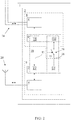
- Fig. 1 shows a first exemplary embodiment of the electrical device 1 in an abstract schematic representation, the electrical device 1 being designed as a field device in this exemplary embodiment.
- the electrical device 1 has the functional device 2 and the measuring device 3.
- the functional device 2 has the first interface device 4 for secure communication, the second interface device 5 for insecure communication, the first microcontroller 6 and the second microcontroller 7.
- the functional device 2 is divided into the safe function block 8 and the unsafe function block 9.
- the first interface device 4 and the first microcontroller 6 are arranged in the safe function block 8 and the measuring device 3 is assigned to the safe function block 8, which is possible because the division into the safe function block 8 and the insecure function block 9 is a functional division.
- the second interface device 5 and the second microcontroller 7 are arranged in the insecure function block 9.
- the functional device 2 only has the first transmission device 10, the first transmission device 10 being designed to transmit first signals exclusively from the secure function block 8 via the first signal path 11 to the insecure function block 9.
- the first transmission device 10 has, in addition to the first signal path 11, the first signal source 12 for the exclusive generation of the first signals and the first signal sink 13 for the exclusive reception of the first signals.
- the first signal source 12 is in the first microcontroller 6 and thus in the safe function block 8 and the first signal sink 13 is in the second microcontroller 7 and thus in the insecure function block 9 implemented.
- the first microcontroller 6 and the second microcontroller 7 are set up in such a way that the first signal source 12 and the first signal sink 13 correspond to a UART (Universal Asynchronous Receiver Transmitter), in which the first signals exclusively from the safe function block 8 via the first signal path 11 to the unsafe function block 9 are transmitted.
- the first microcontroller 6 and the second microcontroller 7 are not set up in such a way that signals can be transmitted from the unsafe function block 9 to the safe function block 8.
- the first interface device 4 and the second interface device 5 are designed for connection to the same line-bound transmission medium 14 and for simultaneous secure communication and unsecure communication.
- the secure communication takes place exclusively via the first interface device 4 and the insecure communication exclusively via the second interface device 5.
- the conductor-based transmission medium 14 is a bus with two conductors, on which both the first interface device 4 and the second interface device 5 are electrically are connected.
- the first interface device 4 is designed exclusively for unidirectional secure communication starting from the first interface device 4, and the second interface device 5 is designed for bidirectional unsecure communication. Since safe communication only takes place unidirectionally from the first interface device 4 during operation of the electrical device 1 and the first signals are transmitted exclusively from the safe function block 8 to the unsafe function block 9, the safe function block 8 is protected against manipulation which could affect the integrity.
- the first interface device 4 implements a current interface and transmits the measurement data encoded by a current strength between 4 mA and 20 mA to the conductor-bound medium 14.
- the first microcontroller 6 determines status data from the measurements and transmits this status data via the first transmission device 10 to the second microcontroller 7.
- the second microcontroller 7 transmits the status data to the second interface device 5 and the second interface device 5 transmits the status data in this embodiment in accordance with HART (Highway Addressable Remote Transducer) to the line-based transmission medium 14.
- HART Highway Addressable Remote Transducer
- data are also transmitted via the line-based transmission medium 14 and the second interface device 5 are transmitted to the second microcontroller 7.
- there is no technical possibility that these data can get from the second microcontroller 7 to the first microcontroller 6.
- Fig. 2 shows in an abstract schematic representation a second embodiment of the electrical device 1, the electrical device 1 being designed as an interface device in this embodiment.
- the electrical device 1 has the functional device 2.
- the functional device 2 for its part has the first interface device 4 for secure communication, the second interface device 5 for insecure communication, the first microcontroller 6 and the second microcontroller 7.
- the functional device 2 is divided into the safe function block 8 and the unsafe function block 9.
- the first interface device 4 and the first microcontroller 6 are arranged in the secure function block 8 and the second interface device 5 and the second microcontroller 7, on the other hand, are arranged in the insecure function block 9.
- the functional device 2 only has the second transmission device 15, the second transmission device 15 being able to be activated and deactivated and the functional device 2 being designed to activate and deactivate the second transmission device 15.
- the first transmission device 10 is designed to transmit first signals exclusively from the secure function block 8 via the electrical first signal path 11 to the insecure function block 9 and the second transmission device 15 is designed to transmit second signals exclusively from the insecure function block 9 via the electrical second signal path 16 to the safe function block 8 is formed.
- the first transmission device 10 has the first signal source 12 for the exclusive generation of the first signals and the first signal sink 13 for the exclusive reception of the first signals.
- the second transmission device 15 has in addition to second signal path 16, the second signal source 17 for the exclusive generation of the second signals and the second signal sink 18 for the exclusive reception of the second signals.
- the functional device 2 has the electrical switch 19, which is arranged in the second signal path 16 and in the safe function block 8.
- the switch 19 is activated and deactivated during operation of the electrical device 1 by the first microcontroller 6 of the functional device 2, for which the first microcontroller 6 is set up accordingly.
- the first microcontroller 6 controls the switch 19 in such a way that the switch 19 is open, the second signal path 16 is interrupted and the second transmission device 15 is thus deactivated.
- the first microcontroller 6 controls the switch 19 in such a way that the switch 19 is closed, the second signal path 16 is uninterrupted and the second transmission device 15 is thus activated.
- the first signal source 12 and the second signal sink 18 are implemented in the first microcontroller 6 and thus in the safe function block 8 and the first signal sink 13 and the second signal source 17 are implemented in the second microcontroller 7 and thus in the insecure function block 9.
- the first microcontroller 6 and the second microcontroller 7 are set up in such a way that the first signal source 12 and the first signal sink 13 correspond to a UART (Universal Asynchronous Receiver Transmitter), in which the first signals exclusively from the safe function block 8 via the first signal path 11 to the unsafe function block 9 are transmitted.
- UART Universal Asynchronous Receiver Transmitter
- the first microcontroller 6 and the second microcontroller 7 are set up in such a way that the second signal source 17 and the second signal sink 18 correspond to a UART (Universal Asynchronous Receiver Transmitter), in which the second signals exclusively from the insecure function block 9 via the second signal path 16 to the insecure one Function block 8 are transmitted when switch 19 is closed.
- UART Universal Asynchronous Receiver Transmitter
- the first interface device 4 and the second interface device 5 are designed for simultaneous secure communication and unsecure communication.
- the secure communication takes place exclusively via the first interface device 4 and the insecure communication exclusively via the second interface device 5.
- the conductor-based transmission medium 14 is a bus with two conductors to which only the first interface device 4 is electrically connected.
- Via the first interface device 4 for example communicates bidirectionally according to HART with a process control system.
- the second interface device 5 has a radio module 20 and also communicates bidirectionally with a remote station in accordance with WLAN.
- the electrical device 1 designed as an interface device ensures through the division into a secure function block 8 and an insecure function block 9 and the described transmission of first signals and second signals between the secure function block 8 and the insecure function block 9 that the connected to the first interface device 4
- Process control system such as the measuring device 3 from the first exemplary embodiment is assigned to the safe function block 8. This results in the same advantages as with the measuring device 3.
- the communication via the first interface 4 and the second interface 5 can be implemented according to different standards. These standards include standards for fieldbuses (HART, CAN, Foundation Fieldbus, Profibus), standards for radio transmission (WLAN, Bluetooth, Zigbee, wireless HART), standards for wired interfaces (Ethernet, EtherCAT) and other standards such as LIN, SPI UART, Current interface (4 mA to 20 mA).
- the first interface device 4 and the second interface device 5 are designed for simultaneous secure communication and unsecure communication.
- the secure communication takes place exclusively via the first interface device 4 and the insecure communication exclusively via the second interface device 5.
- the conductor-based transmission medium 14 is a bus with two conductors to which only the first interface device 4 is electrically connected.
- the first interface device 4 is used for bidirectional communication in accordance with HART with a process control system, for example.
- the second interface device 5 has a radio module 20 and also communicates bidirectionally with a remote station in accordance with WLAN.
- the electrical device 1 designed as an interface device ensures through the division into a secure function block 8 and an insecure function block 9 and the described transmission of first signals and second signals between the secure function block 8 and the insecure function block 9 that the connected to the first interface device 4
- Process control system such as the measuring device 3 from the first exemplary embodiment is assigned to the safe function block 8. This results in the same advantages as with the measuring device 3.
- the communication via the first interface 4 and the second interface 5 can be implemented according to different standards. These standards include standards for fieldbuses (HART, CAN, Foundation Fieldbus, Profibus), standards for radio transmission (WLAN, Bluetooth, Zigbee, wireless HART), standards for wired interfaces (Ethernet, EtherCAT) and other standards such as LIN, SPI UART, Current interface (4 mA to 20 mA).
Description
- Die Erfindung betrifft elektrische Geräte mit einer Funktionseinrichtung. Dabei weist die Funktionseinrichtung eines elektrischen Geräts eine erste Schnittstelleneinrichtung zur sicheren Kommunikation und eine zweite Schnittstelleneinrichtung zur unsicheren Kommunikation auf.
- Ein solches elektrisches Gerät wird zum Beispiel in industriellen Anlagen eingesetzt. Eine industrielle Anlage weist für gewöhnlich eine Vielzahl von Einrichtungen wie zum Beispiel Prozessleitsysteme auf, die über Schnittstelleneinrichtungen miteinander kommunizieren. Kommunikation ist allgemein die Übertragung von Informationen durch Signale. Kommunikation in industriellen Anlagen wird dabei für gewöhnlich unterteilt zum einen in sichere Kommunikation und zum anderen in unsichere Kommunikation. Bei sicherer Kommunikation sind die übertragenen Informationen gegen Manipulationen geschützt, so dass ihre Integrität gewährleistet ist. Bei unsicherer Kommunikation ist das nicht der Fall. Sichere Kommunikation wird durch Maßnahmen angestrebt, die eine Manipulation von Informationen zumindest erschweren und im Idealfall unmöglich machen. Es liegt zum einen im Ermessen des Betreibers einer industriellen Anlage und zum anderen an der Art der industriellen Anlage, was sicher und was unsicher ist. Eine allgemeingültige Definition ist nicht möglich.
- Bei einem elektrischen Gerät in einer industriellen Anlage, das über die erste Schnittstelleneinrichtung zur sicheren Kommunikation und über die zweite Schnittstelleneinrichtung zur unsicheren Kommunikation mit weiteren Einrichtungen der industriellen Anlage verbunden ist, ist durch die Implementierung sowohl der ersten Schnittstelleneinrichtung als auch der zweiten Schnittstelleneinrichtung in der Funktionseinrichtung eine Schwachstelle gegeben. Diese Schwachstelle ermöglicht oftmals mit geringem Aufwand über die zweite Schnittstelleneinrichtung Informationen zu manipulieren, die über die erste Schnittstelleneinrichtung übertragen werden, wodurch die Integrität dieser Informationen beeinträchtigt wird. Manipulierte Informationen können zum Beispiel das elektrische Gerät oder die weiteren Einrichtungen der industriellen Anlage derart beeinflussen, dass das elektrische Gerät und/oder die weiteren Einrichtungen geschädigt oder im Betrieb empfindlich gestört werden.
- Die
US 2013/0117556 offenbart ein System und ein Verfahren zum sicheren Speichern und Übertragen von Daten. - Die
US 2012/030768 offenbart eine integrierte Netzwerkschnittstelle, welche eine sichere Datenübertragung in nur einer Richtung von einem Bereich geringer Sicherheit in einen Bereich höherer Sicherheit gewährleistet. Dazu weist die Netzwerkschnittstelle eine Sendeeinrichtung, eine Empfangseinrichtung und eine Übertragungseinrichtung auf, welche eine Übertragung von Daten nur von der Sendeeinrichtung zur Empfangseinrichtung ermöglicht. Weiter weist die Sendeeinrichtung eine Schnittstelleneinrichtung zur Kommunikation mit dem Bereich der geringen Sicherheit und die Empfangseinrichtung eine Schnittstelleneinrichtung zur Kommunikation mit dem Bereich hoher Sicherheit auf. - Eine Aufgabe der vorliegenden Erfindung ist daher die Angabe von elektrischen Geräten, bei denen die Manipulation von Informationen, die über die erste Schnittstelleneinrichtung übertragen werden, zumindest erschwert ist.
- Die Erfindung ist zunächst und im Wesentlichen dadurch gekennzeichnet, dass die Funktionseinrichtung in einen sicheren Funktionsblock und in einen unsicheren Funktionsblock unterteilt ist und zusätzlich zu einer ersten Übertragungseinrichtung nur noch eine zweite Übertragungseinrichtung aufweist. Dabei ist die erste Schnittstelleneinrichtung im sicheren Funktionsblock und ist die zweite Schnittstelleneinrichtung im unsicheren Funktionsblock angeordnet. Weiterhin ist die erste Übertragungseinrichtung zur Übertragung von ersten Signalen ausschließlich vom sicheren Funktionsblock über einen ersten Signalpfad zum unsicheren Funktionsblock und ist die zweite Übertragungseinrichtung zur Übertragung von zweiten Signalen ausschließlich vom unsicheren Funktionsblock über einen zweiten Signalpfad zum sicheren Funktionsblock ausgebildet. Darüber hinaus ist die zweite Übertragungseinrichtung aktivierbar und deaktivierbar und ist die Funktionseinrichtung ausgebildet, die zweite Übertragungseinrichtung zu aktivieren und zu deaktivieren. Die Ausbildung der Funktionseinrichtung, die zweite Übertragungseinrichtung zu aktivieren und zu deaktivieren, ist dabei im sicheren Funktionsblock angeordnet. In einer Ausgestaltung ist vorgesehen, dass die Funktionseinrichtung zusätzlich im unsicheren Funktionsblock ausgebildet ist, die zweite Übertragungseinrichtung zu aktivieren und zu deaktivieren.
- Die Unterteilung der Funktionseinrichtung in einen sicheren Funktionsblock und in einen unsicheren Funktionsblock ist eine funktionale Aufteilung, wobei das Verständnis von sicher und unsicher in Bezug auf die Funktionsblöcke das Gleiche ist wie in Bezug auf die Kommunikation. Dabei ist diese Unterteilung nicht abschließend, weshalb neben dem sicheren Funktionsblock und dem unsicheren Funktionsblock auch noch weitere Funktionsblöcke in der Funktionseinrichtung vorhanden sein können. Deshalb ist auch die erste Schnittstelleneinrichtung, die zu sicheren Kommunikation dient, dem sicheren Funktionsblock und ist die zweite Schnittstelleneinrichtung, die der unsicheren Kommunikation dient, dem unsicheren Funktionsblock zugeordnet. Der erste Signalpfad der ersten Übertragungseinrichtung und der zweite Signalpfad der zweiten Übertragungseinrichtung sind die beiden einzigen Signalpfade, die eine Kommunikation zwischen dem sicheren Funktionsblock und dem unsicheren Funktionsblock ermöglichen. Dabei erfolgt über den ersten Signalpfad eine Kommunikation ausschließlich vom sicheren Funktionsblock hin zum unsicheren Funktionsblock und erfolgt über den zweiten Signalpfad eine Kommunikation ausschließlich vom unsicheren Funktionsblock hin zum sicheren Funktionsblock.
- Zur Gewährleistung, dass die Manipulation von Informationen, die über die erste Schnittstelleneinrichtung übertragen werden, durch die zweite Schnittstelleneinrichtung zumindest erschwert ist, ist die zweite Übertragungseinrichtung aktivierbar und deaktivierbar, wobei das Aktivieren und das Deaktivieren der zweiten Übertragungseinrichtung durch die Funktionseinrichtung ausgeführt wird, die dazu entsprechend im sicheren Funktionsblock ausgebildet ist. Die zweite Übertragungseinrichtung kann entweder aktiviert oder deaktiviert sein. Wenn die zweite Übertragungseinrichtung aktiviert ist, werden die zweiten Signale vom unsicheren Funktionsblock zum sicheren Funktionsblock übertragen und wenn die zweite Übertragungseinrichtung deaktiviert ist, werden die zweiten Signale nicht vom unsicheren Funktionsblock zum sicheren Funktionsblock übertragen.
- Das erfindungsgemäße elektrische Gerät hat neben dem Vorteil, dass über die zweite Schnittstelleneinrichtung Informationen, die über die erste Schnittstelleneinrichtung übertragen werden, zumindest nur erschwert manipuliert werden können, noch den weiteren Vorteil, dass auch eine Kommunikation vom unsicheren Funktionsblock hin zum sicheren Funktionsblock möglich ist, wenn die zweite Übertragungseinrichtung durch die Funktionseinrichtung aktiviert ist. Die Aktivierung der zweiten Übertragungseinrichtung erfolgt dabei dann und so lange keine Manipulation über die zweite Schnittstelleneinrichtung angenommen werden kann.
- Dadurch, dass die erste Übertragungseinrichtung ausschließlich eine Kommunikation vom sicheren Funktionsblock hin zum unsicheren Funktionsblock und die zweite Übertragungseinrichtung ausschließlich eine Kommunikation vom unsicheren Funktionsblock hin zum sicheren Funktionsblock implementiert und die zweite Übertragungseinrichtung aktivierbar und deaktivierbar ist, ist bei deaktivierter zweiter Übertragungseinrichtung gewährleistet, dass die Anfälligkeit für eine Manipulation von Informationen, die über die erste Schnittstelleneinrichtung übertragen werden, wie beim elektrischen Gerät gemäß der ersten Lehre reduziert ist.
- Die erste Übertragungseinrichtung und die zweite Übertragungseinrichtung können auf verschiedene Weisen implementiert sein. In einer ersten Ausgestaltung des erfindungsgemäßen elektrischen Geräts ist vorgesehen, dass zum einen die erste Übertragungseinrichtung eine erste Signalquelle zur ausschließlichen Erzeugung von den ersten Signalen und eine erste Signalsenke zum ausschließlichen Empfang von den ersten Signalen aufweist. Dabei ist die erste Signalquelle im sicheren Funktionsblock und ist die erste Signalsenke im unsicheren Funktionsblock angeordnet. Zum anderen ist vorgesehen, dass die zweite Übertragungseinrichtung eine zweite Signalquelle zur ausschließlichen Erzeugung von den zweiten Signalen und eine zweite Signalsenke zum ausschließlichen Empfang von den zweiten Signalen aufweist, wobei die zweite Signalquelle im unsicheren Funktionsblock und die zweite Signalsenke im sicheren Funktionsblock angeordnet sind. Dabei verbindet der erste Signalpfad die erste Signalquelle und die erste Signalsenke vorzugsweise unmittelbar miteinander, so dass die von der ersten Signalquelle erzeugten ersten Signale über den ersten Signalpfad zur ersten Signalsenke übertragen werden. Entsprechend verbindet der zweite Signalpfad die zweite Signalquelle und die zweite Signalsenke vorzugsweise unmittelbar miteinander, so dass die von der zweiten Signalquelle erzeugten zweiten Signale über den zweiten Signalpfad zur zweiten Signalsenke übertragen werden.
- Es bietet sich an, die erste Übertragungseinrichtung und/oder die zweite Übertragungseinrichtung gemäß einem Standard auszubilden. Zu diesen Standards zählen insbesondere UART, RS-232, EIA-485, SPI, LIN, I2C.
- Signalquellen und Signalsenken können auf verschiedene Weisen implementiert sein. Deshalb ist in einer weiteren Ausgestaltung des elektrischen Geräts vorgesehen, dass die erste Signalquelle und/oder die zweite Signalsenke durch mindestens einen ersten Mikrocontroller implementiert sind bzw. ist und/oder dass die zweite Signalquelle und/oder die erste Signalsenke durch mindestens einen zweiten Mikrocontroller implementiert sind bzw. ist. Vorzugsweise sind die erste Signalquelle und die zweite Signalsenke durch einen ersten Mikrocontroller implementiert und sind die zweite Signalquelle und die erste Signalsenke durch einen zweiten Mikrocontroller implementiert, was zu einer besonders kostengünstigen Implementierung beiträgt, da nur zwei Mikrocontroller benötigt werden. Dabei ist der mindestens eine erste Mikrocontroller, der die erste Signalquelle und/oder die zweite Signalsenke implementiert, im sicheren Funktionsblock und ist der mindestens eine zweite Mikrocontroller, der die zweite Signalquelle und/oder die erste Signalsenke implementiert, im unsicheren Funktionsblock angeordnet.
- Zur Gewährleistung, dass unter Verwendung der zweiten Schnittstelleneinrichtung Informationen, die über die erste Schnittstelleneinrichtung übertragen werden, zumindest nur erschwert manipuliert werden können, ist die zweite Übertragungseinrichtung aktivierbar und deaktivierbar ausgelegt. Die Aktivierbarkeit und die Deaktivierbarkeit der zweiten Übertragungseinrichtung kann auf verschiedene Weisen implementiert sein. In einer ersten Ausgestaltung ist vorgesehen, dass die zweite Übertragungseinrichtung durch einen Schalter im zweiten Signalpfad aktivierbar und deaktivierbar ist. Dabei wird der Schalter durch die Funktionseinrichtung aktiviert und deaktiviert, wozu die Funktionseinrichtung im sicheren Funktionsblock entsprechend ausgebildet ist. Wenn der zweite Signalpfad ein elektrischer Signalpfad ist, kann als Schalter zum Beispiel ein elektrischer Schalter verwendet werden, der den zweiten Signalpfad unterbricht, wenn die zweite Übertragungseinrichtung deaktiviert ist und den zweiten Signalpfad nicht unterbricht, wenn die zweite Übertragungseinrichtung aktiviert ist.
- In einer zur vorangehenden Ausgestaltung alternativen oder zusätzlichen Ausgestaltung ist vorgesehen, dass die zweite Übertragungseinrichtung durch ein Aktivieren oder Deaktivieren der zweiten Signalquelle und/oder der zweiten Signalsenke aktivierbar und deaktivierbar ist. Diese Ausgestaltung ist insbesondere dann vorteilhaft und einfach zu implementieren, wenn die zweite Signalquelle durch einen Mikrocontroller und/oder die zweite Signalsenke durch einen Mikrocontroller implementiert sind bzw. ist. Mikrocontroller weisen für gewöhnlich frei konfigurierbare Anschlüsse auf, die sowohl als Signalquelle als auch als Signalsenke durch Programmierung des Mikrocontrollers konfiguriert werden können. Darüber hinaus implementieren Mikrocontroller oftmals auch Standards wie z. B. UART. Somit ist es möglich, die zweite Signalquelle und/oder die zweite Signalsenke zu aktivieren oder zu deaktivieren, indem ein frei konfigurierbarer Anschluss eines Mikrocontrollers aktiviert oder deaktiviert wird oder indem die UART aktiviert oder deaktiviert wird. Für gewöhnlich weist eine UART auch einen Eingangsbuffer auf. Dann kann die zweite Signalsenke auch durch ein Nichtauslesen des Eingangsbuffers deaktiviert werden. Entsprechend wird die zweite Signalsenke durch ein Auslesen des Eingangsbuffers aktiviert. Diese Umsetzung erfolgt vollständig durch Programmierung.
- In einer weiteren Ausgestaltung des elektrischen Geräts sowohl gemäß der ersten Lehre als auch gemäß der zweiten Lehre ist vorgesehen, dass das elektrische Gerät ein Feldgerät ist. Feldgeräte sind elektrische Geräte im Bereich der Automatisierungs- und Prozesstechnik, die mit einem Prozess in unmittelbarer Beziehung stehen.
- In einer weiteren Ausgestaltung ist vorgesehen, dass die Funktionseinrichtung eine Messeinrichtung aufweist und die Messeinrichtung dem sicheren Funktionsblock zugeordnet ist. Die Zuordnung der Messeinrichtung zum sicheren Funktionsblock bedeutet, dass eine Kommunikation mit der Messeinrichtung nur über den sicheren Funktionsblock möglich ist, wodurch gewährleistet ist, dass von der Messeinrichtung bestimmte Messdaten gegen Manipulationen geschützt sind.
- Um die Anzahl von leitergebundenen Übertragungsmedien zu reduzieren, ist in einer weiteren Ausgestaltung ist vorgesehen, dass die erste Schnittstelleneinrichtung und die zweite Schnittstelleneinrichtung zur Verbindung mit demselben leitergebundenen Übertragungsmedium und zur gleichzeitigen sicheren Kommunikation und unsicheren Kommunikation ausgebildet sind. Die gleichzeitige Übertragung von Informationen über die erste Schnittstelleneinrichtung und über die zweite Schnittstelleneinrichtung über dasselbe leitergebundene Übertragungsmedium erfordert, dass die Signale, die gleichzeitig über die erste Schnittstelle und über die zweite Schnittstelle übertragen werden und die Informationen enthalten, voneinander unterscheidbar sind.
- In einer weiteren Ausgestaltung ist vorgesehen, dass die erste Schnittstelleneinrichtung ausschließlich zur unidirektionalen sicheren Kommunikation ausgehend von der ersten Schnittstelleneinrichtung ausgebildet ist. Somit ist über die erste Schnittstelleneinrichtung keine Kommunikation hinein in den sicheren Funktionsblock möglich, wodurch eine Manipulation weiter erschwert wird.
- In einer weiteren Ausgestaltung ist vorgesehen, dass die zweite Schnittstelleneinrichtung zur bidirektionalen unsicheren Kommunikation ausgebildet ist.
- Im Einzelnen ist eine Vielzahl von Möglichkeiten gegeben, die elektrischen Geräte auszugestalten und weiterzubilden. Dazu wird verwiesen sowohl auf die den unabhängigen Patentansprüchen nachgeordneten Patentansprüche als auch auf die nachfolgende Beschreibung von bevorzugten Ausführungsbeispielen in Verbindung mit der Zeichnung. In der Zeichnung zeigt
- Fig. 1
- ein erstes Ausführungsbeispiels eines elektrischen Geräts und
- Fig. 2
- ein zweites Ausführungsbeispiel eines elektrischen Geräts.
-
Fig. 1 zeigt in einer abstrahierten schematischen Darstellung ein erstes Ausführungsbeispiel des elektrischen Geräts 1, wobei das elektrische Gerät 1 in diesem Ausführungsbeispiel als Feldgerät ausgeführt ist. Das elektrische Gerät 1 weist die Funktionseinrichtung 2 und die Messeinrichtung 3 auf. - Die Funktionseinrichtung 2 weist die erste Schnittstelleneinrichtung 4 zur sicheren Kommunikation, die zweite Schnittstelleneinrichtung 5 zur unsicheren Kommunikation, den ersten Mikrocontroller 6 und den zweiten Mikrocontroller 7 auf. Die Funktionseinrichtung 2 ist in den sicheren Funktionsblock 8 und in den unsicheren Funktionsblock 9 unterteilt. Die erste Schnittstelleneinrichtung 4 und der erste Mikrocontroller 6 sind im sicheren Funktionsblock 8 angeordnet und die Messeinrichtung 3 ist dem sicheren Funktionsblock 8 zugeordnet, was möglich ist, da die Aufteilung in den sicheren Funktionsblock 8 und in den unsicheren Funktionsblock 9 eine funktionale Aufteilung ist. Die zweite Schnittstelleneinrichtung 5 und der zweite Mikrocontroller 7 sind dagegen in dem unsicheren Funktionsblock 9 angeordnet.
- Darüber hinaus weist die Funktionseinrichtung 2 nur die erste Übertragungseinrichtung 10 auf, wobei die erste Übertragungseinrichtung 10 zur Übertragung von ersten Signalen ausschließlich vom sicheren Funktionsblock 8 über den ersten Signalpfad 11 zum unsicheren Funktionsblock 9 ausgebildet ist. Die erste Übertragungseinrichtung 10 weist dazu neben dem ersten Signalpfad 11 die erste Signalquelle 12 zur ausschließlichen Erzeugung von den ersten Signalen und die erste Signalsenke 13 zum ausschließlichen Empfang von den ersten Signalen auf. Die erste Signalquelle 12 ist dabei im ersten Mikrocontroller 6 und somit im sicheren Funktionsblock 8 und die erste Signalsenke 13 ist im zweiten Mikrocontroller 7 und somit im unsicheren Funktionsblock 9 implementiert. Der erste Mikrocontroller 6 und der zweite Mikrocontroller 7 sind dabei derart eingerichtet, dass die erste Signalquelle 12 und die erste Signalsenke 13 einer UART (Universal Asynchronous Receiver Transmitter) entsprechen, bei der die ersten Signale ausschließlich vom sicheren Funktionsblock 8 über den ersten Signalpfad 11 zum unsichereren Funktionsblock 9 übertragen werden. Der erste Mikrocontroller 6 und der zweite Mikrocontroller 7 sind nicht derart eingerichtet, dass eine Übertragung von Signalen vom unsicheren Funktionsblock 9 hin zum sicheren Funktionsblock 8 möglich ist.
- Die erste Schnittstelleneinrichtung 4 und die zweite Schnittstelleneinrichtung 5 sind zur Verbindung mit demselben leitergebundenen Übertragungsmedium 14 und zur gleichzeitigen sicheren Kommunikation und unsicheren Kommunikation ausgebildet. Dabei erfolgt die sichere Kommunikation ausschließlich über die erste Schnittstelleneinrichtung 4 und die unsichere Kommunikation ausschließlich über die zweite Schnittstelleneinrichtung 5. Im vorliegenden Ausführungsbeispiel ist das leitergebundene Übertragungsmedium 14 ein Bus mit zwei Leitern, an dem sowohl die erste Schnittstelleneinrichtung 4 als auch die zweite Schnittstelleneinrichtung 5 elektrisch angeschlossen sind. Die erste Schnittstelleneinrichtung 4 ist dabei ausschließlich zur unidirektionalen sicheren Kommunikation ausgehend von der ersten Schnittstelleneinrichtung 4 und die zweite Schnittstelleneinrichtung 5 ist zur bidirektionalen unsicheren Kommunikation ausgebildet. Da im Betrieb des elektrischen Geräts 1 sichere Kommunikation nur unidirektional ausgehend von der ersten Schnittstelleneinrichtung 4 stattfindet und die ersten Signale ausschließlich vom sicheren Funktionsblock 8 zum unsicheren Funktionsblock 9 übertragen werden, ist der sichere Funktionsbock 8 gegen Manipulation geschützt, welche die Integrität beeinflussen könnten.
- Im Betrieb des elektrischen Geräts 1 werden gesteuert von dem ersten Mikrocontroller 6 von der Messeinrichtung 3 Messungen durchgeführt und Messdaten ermittelt. Die ermittelten Messdaten werden unidirektional durch die erste Schnittstelleneinrichtung 4 auf das leitergebundene Übertragungsmedium 14 übertragen. Dazu implementiert die erste Schnittstelleneinrichtung 4 in diesem Ausführungsbeispiel eine Stromschnittstelle und überträgt die durch eine Stromstärke zwischen 4 mA und 20 mA codierten Messdaten auf das leitergebundene Medium 14.
- Darüber hinaus bestimmt der erste Mikrocontroller 6 aus den Messungen Statusdaten und überträgt diese Statusdaten über die erste Übertragungseinrichtung 10 zum zweiten Mikrocontroller 7. Der zweite Mikrocontroller 7 überträgt die Statusdaten zur zweiten Schnittstelleneinrichtung 5 und die zweite Schnittstelleneinrichtung 5 überträgt die Statusdaten in diesem Ausführungsbeispiel gemäß HART (Highway Addressable Remote Transducer) auf das leitergebundene Übertragungsmedium 14. Weiterhin werden auch Daten über das leitergebundene Übertragungsmedium 14 und die zweite Schnittstelleneinrichtung 5 an den zweiten Mikrocontroller 7 übertragen. Jedoch besteht keine technische Möglichkeit, dass diese Daten vom zweiten Mikrocontroller 7 zum ersten Mikrocontroller 6 gelangen können.
-
Fig. 2 zeigt in einer abstrahierten schematischen Darstellung ein zweites Ausführungsbeispiel des elektrischen Geräts 1, wobei das elektrische Gerät 1 in diesem Ausführungsbeispiel als Schnittstellengerät ausgeführt ist. - Das elektrische Gerät 1 weist die Funktionseinrichtung 2 auf. Die Funktionseinrichtung 2 weist ihrerseits die erste Schnittstelleneinrichtung 4 zur sicheren Kommunikation, die zweite Schnittstelleneinrichtung 5 zur unsicheren Kommunikation, den ersten Mikrocontroller 6 und den zweiten Mikrocontroller 7 auf. Die Funktionseinrichtung 2 ist in den sicheren Funktionsblock 8 und in den unsicheren Funktionsblock 9 unterteilt. Die erste Schnittstelleneinrichtung 4 und der erste Mikrocontroller 6 sind im sicheren Funktionsblock 8 und die zweite Schnittstelleneinrichtung 5 und der zweite Mikrocontroller 7 sind dagegen im unsicheren Funktionsblock 9 angeordnet.
- Darüber hinaus weist die Funktionseinrichtung 2 zusätzlich zu der ersten Übertragungseinrichtung 10 nur noch die zweite Übertragungseinrichtung 15 auf, wobei die zweite Übertragungseinrichtung 15 aktivierbar und deaktivierbar ist und die Funktionseinrichtung 2 ausgebildet ist, die zweite Übertragungseinrichtung 15 zu aktivieren und zu deaktivieren. Dabei ist die erste Übertragungseinrichtung 10 zur Übertragung von ersten Signalen ausschließlich vom sicheren Funktionsblock 8 über den elektrischen ersten Signalpfad 11 zum unsicheren Funktionsblock 9 ausgebildet und ist die zweite Übertragungseinrichtung 15 zur Übertragung von zweiten Signalen ausschließlich vom unsicheren Funktionsblock 9 über den elektrischen zweiten Signalpfad 16 zum sicheren Funktionsblock 8 ausgebildet.
- Die erste Übertragungseinrichtung 10 weist neben dem ersten Signalpfad 11 die erste Signalquelle 12 zur ausschließlichen Erzeugung von den ersten Signalen und die erste Signalsenke 13 zum ausschließlichen Empfang von den ersten Signalen auf. Die zweite Übertragungseinrichtung 15 weist neben dem zweiten Signalpfad 16 die zweite Signalquelle 17 zur ausschließlichen Erzeugung von den zweiten Signalen und die zweite Signalsenke 18 zum ausschließlichen Empfang von den zweiten Signalen auf.
- Darüber hinaus weist die Funktionseinrichtung 2 den elektrischen Schalter 19 auf, der im zweiten Signalpfad 16 und im sicheren Funktionsblock 8 angeordnet ist. Der Schalter 19 wird im Betrieb des elektrischen Geräts 1 durch den ersten Mikrocontroller 6 der Funktionseinrichtung 2 aktiviert und deaktiviert, wozu der erste Mikrocontroller 6 entsprechend eingerichtet ist. Wenn der erste Mikrocontroller 6 den Schalter 19 derart ansteuert, dass der Schalter 19 geöffnet ist, ist der zweite Signalpfad 16 unterbrochen und die zweite Übertragungseinrichtung 15 somit deaktiviert. Wenn der erste Mikrocontroller 6 den Schalter 19 derart ansteuert, dass der Schalter 19 geschlossen ist, ist der zweite Signalpfad 16 unterbrechungsfrei und die zweite Übertragungseinrichtung 15 somit aktiviert.
- Die erste Signalquelle 12 und die zweite Signalsenke 18 sind im ersten Mikrocontroller 6 und somit im sicheren Funktionsblock 8 und die erste Signalsenke 13 und die zweite Signalquelle 17 sind im zweiten Mikrocontroller 7 und somit im unsicheren Funktionsblock 9 implementiert. Der erste Mikrocontroller 6 und der zweite Mikrocontroller 7 sind dabei derart eingerichtet, dass die erste Signalquelle 12 und die erste Signalsenke 13 einer UART (Universal Asynchronous Receiver Transmitter) entsprechen, bei der die ersten Signale ausschließlich vom sicheren Funktionsblock 8 über den ersten Signalpfad 11 zum unsichereren Funktionsblock 9 übertragen werden. Weiterhin sind erste Mikrocontroller 6 und der zweite Mikrocontroller 7 derart eingerichtet, dass die zweite Signalquelle 17 und die zweite Signalsenke 18 einer UART (Universal Asynchronous Receiver Transmitter) entsprechen, bei der die zweiten Signale ausschließlich vom unsicheren Funktionsblock 9 über den zweiten Signalpfad 16 zum unsichereren Funktionsblock 8 übertragen werden, wenn der Schalter 19 geschlossen ist.
- Die erste Schnittstelleneinrichtung 4 und die zweite Schnittstelleneinrichtung 5 sind zur gleichzeitigen sicheren Kommunikation und unsicheren Kommunikation ausgebildet. Dabei erfolgt die sichere Kommunikation ausschließlich über die erste Schnittstelleneinrichtung 4 und die unsichere Kommunikation ausschließlich über die zweite Schnittstelleneinrichtung 5. Im vorliegenden Ausführungsbeispiel ist das leitergebundene Übertragungsmedium 14 ein Bus mit zwei Leitern, an dem nur die erste Schnittstelleneinrichtung 4 elektrisch angeschlossen ist. Über die erste Schnittstelleneinrichtung 4 wird zum Beispiel mit einem Prozessleitsystem bidirektional gemäß HART kommuniziert. Die zweite Schnittstelleneinrichtung 5 weist in diesem Ausführungsbeispiel ein Funkmodul 20 auf und kommuniziert ebenfalls bidirektional mit einer Gegenstelle gemäß WLAN. Das als Schnittstellengerät ausgeführte elektrische Gerät 1 gewährleistet durch die Aufteilung in einen sicheren Funktionsblock 8 und einen unsicheren Funktionsblock 9 und die beschriebene Übertragung von ersten Signalen und zweiten Signalen zwischen dem sicheren Funktionsblock 8 und dem unsicheren Funktionsblock 9, dass das an der ersten Schnittstelleneinrichtung 4 angeschlossene Prozessleitsystem wie die Messeinrichtung 3 aus dem ersten Ausführungsbeispiel dem sicheren Funktionsblock 8 zugeordnet wird. Somit ergeben sich die gleichen Vorteile wie bei der Messeinrichtung 3.
- Die Kommunikation über die erste Schnittstelle 4 und die zweite Schnittstelle 5 kann gemäß verschiedenen Standards implementiert sein. Zu diesen Standards gehören Standards für Feldbusse (HART, CAN, Foundation Fieldbus, Profibus), Standards für Funkübertragung (WLAN, Bluetooth, Zigbee, wireless HART), Standards für kabelgebundene Schnittstellen (Ethernet, EtherCAT) und weitere Standards wie LIN, SPI UART, Stromschnittstelle (4 mA bis 20 mA).
-
- 1
- Elektrisches Gerät
- 2
- Funktionseinrichtung
- 3
- Messeinrichtung
- 4
- Erste Schnittstelleneinrichtung zur sicheren Kommunikation
- 5
- Zweite Schnittstelleneinrichtung zur unsicheren Kommunikation
- 6
- Erster Mikrocontroller
- 7
- Zweiter Mikrocontroller
- 8
- Sicherer Funktionsblock
- 9
- Unsicherer Funktionsblock
- 10
- Erste Übertragungseinrichtung
- 11
- Erster Signalpfad
- 12
- Erste Signalquelle
- 13
- Erst Signalsenke
- 14
- Leitungsgebundenes Übertragungsmedium
- 15
- Zweite Übertragungseinrichtung
- 16
- Zweiter Signalpfad
- 17
- Zweite Signalquelle
- 18
- Zweite Signalsenke
- 19
- Elektrischer Schalter
- 20
- Funkmodul
Claims (11)
- Elektrisches Gerät (1) mit einer Funktionseinrichtung (2),
wobei die Funktionseinrichtung (2) eine erste Schnittstelleneinrichtung (4) zur sicheren Kommunikation und eine zweite Schnittstelleneinrichtung (5) zur unsicheren Kommunikation aufweist,
dadurch gekennzeichnet,
dass die Funktionseinrichtung (2) in einen sicheren Funktionsblock (8) und einen unsicheren Funktionsblock (9) unterteilt ist und zusätzlich zu einer ersten Übertragungseinrichtung (10) nur noch eine zweite Übertragungseinrichtung (15) aufweist,
dass die erste Schnittstelleneinrichtung (4) im sicheren Funktionsblock (8) und die zweite Schnittstelleneinrichtung (5) im unsicheren Funktionsblock (9) angeordnet sind,
dass die erste Übertragungseinrichtung (10) zur Übertragung von ersten Signalen ausschließlich vom sicheren Funktionsblock (8) über einen ersten Signalpfad (11) zum unsicheren Funktionsblock (9) und die zweite Übertragungseinrichtung (15) zur Übertragung von zweiten Signalen ausschließlich vom unsicheren Funktionsblock (9) über einen zweiten Signalpfad (16) zum sicheren Funktionsblock (8) ausgebildet sind,
dass die zweite Übertragungseinrichtung (15) aktivierbar und deaktivierbar ist und
dass die Funktionseinrichtung (2) im sicheren Funktionsblock (8) ausgebildet ist, die zweite Übertragungseinrichtung (15) zu aktivieren und zu deaktivieren. - Elektrisches Gerät (1) nach Anspruch 1, dadurch gekennzeichnet, dass die Funktionseinrichtung (2) im unsicheren Funktionsblock (9) ausgebildet ist, die zweite Übertragungseinrichtung (15) zu aktivieren und zu deaktivieren.
- Elektrisches Gerät (1) nach Anspruch 1 oder 2, dadurch gekennzeichnet,
dass die erste Übertragungseinrichtung (10) eine erste Signalquelle (12) zur ausschließlichen Erzeugung von den ersten Signalen und eine erste Signalsenke (13) zum ausschließlichen Empfang von den ersten Signalen aufweist, wobei die erste Signalquelle (12) im sicheren Funktionsblock (8) und die erste Signalsenke (13) im unsicheren Funktionsblock (9) angeordnet sind und dass die zweite Übertragungseinrichtung (15) eine zweite Signalquelle (17) zur ausschließlichen Erzeugung von den zweiten Signalen und eine zweite Signalsenke (18) zum ausschließlichen Empfang von den zweiten Signalen aufweist, wobei die zweite Signalquelle (17) im unsicheren Funktionsblock (9) und die zweite Signalsenke (18) im sicheren Funktionsblock (8) angeordnet sind. - Elektrisches Gerät (1) nach Anspruch 3, dadurch gekennzeichnet, dass die erste Signalquelle (12) und/oder die zweite Signalsenke (18) durch mindestens einen ersten Mikrocontroller (6) implementiert sind bzw. ist und/oder dass die zweite Signalquelle (17) und/oder die erste Signalsenke (13) durch mindestens einen zweiten Mikrocontroller (7) implementiert sind bzw. ist.
- Elektrisches Gerät (1) nach einem der Ansprüche 1 bis 4, dadurch gekennzeichnet, dass die zweite Übertragungseinrichtung (15) durch einen Schalter (19) im zweiten Signalpfad (16) aktivierbar und deaktivierbar ist.
- Elektrisches Gerät (1) nach einem der Ansprüche 1 bis 5, dadurch gekennzeichnet, dass die zweite Übertragungseinrichtung (15) durch ein Aktivieren oder Deaktivieren der zweiten Signalquelle (17) und/oder der zweiten Signalsenke (18) aktivierbar und deaktivierbar ist.
- Elektrisches Gerät (1) nach einem der Ansprüche 1 bis 6, dadurch gekennzeichnet, dass das elektrische Gerät (1) ein Feldgerät ist.
- Elektrisches Gerät (1) nach einem der Ansprüche 1 bis 7, dadurch gekennzeichnet, dass das elektrische Gerät (1) eine Messeinrichtung (3) aufweist und die Messeinrichtung (3) dem sicheren Funktionsblock (8) zugeordnet ist.
- Elektrisches Gerät (1) nach einem der Ansprüche 1 bis 8, dadurch gekennzeichnet, dass die erste Schnittstelleneinrichtung (4) und die zweite Schnittstelleneinrichtung (5) zur Verbindung mit demselben leitergebundenen Übertragungsmedium (14) und zur gleichzeitigen sicheren Kommunikation und unsicheren Kommunikation ausgebildet sind.
- Elektrisches Gerät (1) nach einem der Ansprüche 1 bis 9, dadurch gekennzeichnet, dass die erste Schnittstelleneinrichtung (4) ausschließlich zur unidirektionalen sicheren Kommunikation ausgehend von der ersten Schnittstelleneinrichtung (4) ausgebildet ist.
- Elektrisches Gerät (1) nach einem der Ansprüche 1 bis 10, dadurch gekennzeichnet, dass die zweite Schnittstelleneinrichtung (5) zur bidirektionalen unsicheren Kommunikation ausgebildet ist.
Applications Claiming Priority (2)
| Application Number | Priority Date | Filing Date | Title |
|---|---|---|---|
| DE102016108062 | 2016-04-30 | ||
| DE102016116152.7A DE102016116152A1 (de) | 2016-04-30 | 2016-08-30 | Elektrisches Gerät mit einer Funktionseinrichtung |
Publications (2)
| Publication Number | Publication Date |
|---|---|
| EP3244274A1 EP3244274A1 (de) | 2017-11-15 |
| EP3244274B1 true EP3244274B1 (de) | 2021-01-27 |
Family
ID=58701374
Family Applications (1)
| Application Number | Title | Priority Date | Filing Date |
|---|---|---|---|
| EP17165854.5A Active EP3244274B1 (de) | 2016-04-30 | 2017-04-11 | Elektrisches gerät mit einer funktionseinrichtung |
Country Status (1)
| Country | Link |
|---|---|
| EP (1) | EP3244274B1 (de) |
Families Citing this family (2)
| Publication number | Priority date | Publication date | Assignee | Title |
|---|---|---|---|---|
| DE102018100629A1 (de) * | 2018-01-12 | 2019-07-18 | Krohne Messtechnik Gmbh | System mit einem elektrischen Gerät |
| DE102018119411A1 (de) * | 2018-08-09 | 2020-02-13 | Endress+Hauser Process Solutions Ag | Feldgerät der Automatisierungstechnik |
Family Cites Families (3)
| Publication number | Priority date | Publication date | Assignee | Title |
|---|---|---|---|---|
| US9305189B2 (en) * | 2009-04-14 | 2016-04-05 | Owl Computing Technologies, Inc. | Ruggedized, compact and integrated one-way controlled interface to enforce confidentiality of a secure enclave |
| US9473300B2 (en) * | 2011-11-03 | 2016-10-18 | Savannah River Nuclear Solutions, Llc | Authenticated sensor interface device |
| AU2014213772A1 (en) * | 2013-02-08 | 2015-08-20 | Bae Systems Plc | A data processing method and apparatus |
-
2017
- 2017-04-11 EP EP17165854.5A patent/EP3244274B1/de active Active
Non-Patent Citations (1)
| Title |
|---|
| None * |
Also Published As
| Publication number | Publication date |
|---|---|
| EP3244274A1 (de) | 2017-11-15 |
Similar Documents
| Publication | Publication Date | Title |
|---|---|---|
| EP2984530B1 (de) | Messumformerspeisegerät mit abschaltbarer funkschnittstelle | |
| DE102012014681B4 (de) | Verwendung eines lO-Links zur Anbindung eines Netzgerätes | |
| DE19646219A1 (de) | Schaltung für die Kommunikation externer Geräte mit einer zentralen/dezentralen Datenverarbeitungsanlage über einen Bus | |
| CH702454A1 (de) | Anordnung mit einer übergeordneten Steuereinheit und zumindest einem mit der Steuereinheit verbindbaren intelligenten Feldgerät. | |
| DE102011114077A1 (de) | PLC System | |
| DE102017208833A1 (de) | Moduleinheit | |
| EP3244274B1 (de) | Elektrisches gerät mit einer funktionseinrichtung | |
| DE102016000126A1 (de) | Serielles Bussystem mit Koppelmodulen | |
| DE102016116152A1 (de) | Elektrisches Gerät mit einer Funktionseinrichtung | |
| DE102014001462B4 (de) | Feldbusmodul, Maschinensteuerung und Verfahren zur Parametrierung eines, insbesondere sicherheitsgerichteten, Feldbusmoduls | |
| DE102014006148B4 (de) | Endgerät für ein Automatisierungssystem, Endgeräteanordnung sowie Verfahren zum Betreiben eines Endgeräts für ein Automatisierungssystem | |
| EP2701019B1 (de) | Verfahren zur Parametrierung eines Feldgerätes und entsprechendes System zur Parametrierung | |
| EP3133447B1 (de) | Sicherheitsschalter | |
| DE19710137B4 (de) | Verfahren und Vorrichtung zur Erweiterung der räumlichen Ausdehnung bei Sensor-Aktuator-Bussystemen | |
| DE102014208839B4 (de) | Verfahren zur sicheren Datenübertragung zwischen einer Automatisierungsanlage und einer IT-Komponente | |
| WO2019096629A1 (de) | Kommunikationssystem der automatisierungs- und prozesstechnik sowie y-weicheneinheit für ein solches kommunikationssystem | |
| WO1997049017A1 (de) | Schaltung für die kommunikation externer geräte mit einer zentralen/dezentralen datenverarbeitungsanlage über einen bus | |
| EP3056953A1 (de) | Autarkes Feldgerät der Automatisierungstechnik zur Fernüberwachung | |
| EP3512177B1 (de) | System mit einem elektrischen gerät | |
| EP3439245A1 (de) | Datenübertragungsverfahren zwischen einem drehwinkelgeber und einer motorsteuereinrichtung oder einer auswerteeinheit | |
| EP2187278A1 (de) | Steuerungsanbindung eines Sicherheitsschaltgerätes | |
| EP2283426B1 (de) | Verfahren und vorrichtung zur korrektur von digital übertragenen informationen | |
| DE102016119744A1 (de) | Verfahren und System zum Verhindern eines unerwünschten Zugriffs auf ein Feldgerät | |
| EP2685670A1 (de) | Bustransceiver | |
| DE10359898A1 (de) | Verfahren zum Steuern und Überwachen von Maschinen |
Legal Events
| Date | Code | Title | Description |
|---|---|---|---|
| PUAI | Public reference made under article 153(3) epc to a published international application that has entered the european phase |
Free format text: ORIGINAL CODE: 0009012 |
|
| STAA | Information on the status of an ep patent application or granted ep patent |
Free format text: STATUS: THE APPLICATION HAS BEEN PUBLISHED |
|
| AK | Designated contracting states |
Kind code of ref document: A1 Designated state(s): AL AT BE BG CH CY CZ DE DK EE ES FI FR GB GR HR HU IE IS IT LI LT LU LV MC MK MT NL NO PL PT RO RS SE SI SK SM TR |
|
| AX | Request for extension of the european patent |
Extension state: BA ME |
|
| STAA | Information on the status of an ep patent application or granted ep patent |
Free format text: STATUS: REQUEST FOR EXAMINATION WAS MADE |
|
| 17P | Request for examination filed |
Effective date: 20180514 |
|
| RBV | Designated contracting states (corrected) |
Designated state(s): AL AT BE BG CH CY CZ DE DK EE ES FI FR GB GR HR HU IE IS IT LI LT LU LV MC MK MT NL NO PL PT RO RS SE SI SK SM TR |
|
| GRAP | Despatch of communication of intention to grant a patent |
Free format text: ORIGINAL CODE: EPIDOSNIGR1 |
|
| STAA | Information on the status of an ep patent application or granted ep patent |
Free format text: STATUS: GRANT OF PATENT IS INTENDED |
|
| INTG | Intention to grant announced |
Effective date: 20200407 |
|
| GRAJ | Information related to disapproval of communication of intention to grant by the applicant or resumption of examination proceedings by the epo deleted |
Free format text: ORIGINAL CODE: EPIDOSDIGR1 |
|
| STAA | Information on the status of an ep patent application or granted ep patent |
Free format text: STATUS: REQUEST FOR EXAMINATION WAS MADE |
|
| INTC | Intention to grant announced (deleted) | ||
| GRAP | Despatch of communication of intention to grant a patent |
Free format text: ORIGINAL CODE: EPIDOSNIGR1 |
|
| STAA | Information on the status of an ep patent application or granted ep patent |
Free format text: STATUS: GRANT OF PATENT IS INTENDED |
|
| GRAS | Grant fee paid |
Free format text: ORIGINAL CODE: EPIDOSNIGR3 |
|
| INTG | Intention to grant announced |
Effective date: 20200918 |
|
| GRAF | Information related to payment of grant fee modified |
Free format text: ORIGINAL CODE: EPIDOSCIGR3 |
|
| GRAA | (expected) grant |
Free format text: ORIGINAL CODE: 0009210 |
|
| STAA | Information on the status of an ep patent application or granted ep patent |
Free format text: STATUS: THE PATENT HAS BEEN GRANTED |
|
| AK | Designated contracting states |
Kind code of ref document: B1 Designated state(s): AL AT BE BG CH CY CZ DE DK EE ES FI FR GB GR HR HU IE IS IT LI LT LU LV MC MK MT NL NO PL PT RO RS SE SI SK SM TR |
|
| REG | Reference to a national code |
Ref country code: GB Ref legal event code: FG4D Free format text: NOT ENGLISH |
|
| REG | Reference to a national code |
Ref country code: CH Ref legal event code: EP |
|
| REG | Reference to a national code |
Ref country code: AT Ref legal event code: REF Ref document number: 1358931 Country of ref document: AT Kind code of ref document: T Effective date: 20210215 |
|
| REG | Reference to a national code |
Ref country code: IE Ref legal event code: FG4D Free format text: LANGUAGE OF EP DOCUMENT: GERMAN |
|
| REG | Reference to a national code |
Ref country code: DE Ref legal event code: R096 Ref document number: 502017009194 Country of ref document: DE |
|
| REG | Reference to a national code |
Ref country code: NL Ref legal event code: FP |
|
| REG | Reference to a national code |
Ref country code: LT Ref legal event code: MG9D |
|
| PG25 | Lapsed in a contracting state [announced via postgrant information from national office to epo] |
Ref country code: HR Free format text: LAPSE BECAUSE OF FAILURE TO SUBMIT A TRANSLATION OF THE DESCRIPTION OR TO PAY THE FEE WITHIN THE PRESCRIBED TIME-LIMIT Effective date: 20210127 Ref country code: GR Free format text: LAPSE BECAUSE OF FAILURE TO SUBMIT A TRANSLATION OF THE DESCRIPTION OR TO PAY THE FEE WITHIN THE PRESCRIBED TIME-LIMIT Effective date: 20210428 Ref country code: FI Free format text: LAPSE BECAUSE OF FAILURE TO SUBMIT A TRANSLATION OF THE DESCRIPTION OR TO PAY THE FEE WITHIN THE PRESCRIBED TIME-LIMIT Effective date: 20210127 Ref country code: PT Free format text: LAPSE BECAUSE OF FAILURE TO SUBMIT A TRANSLATION OF THE DESCRIPTION OR TO PAY THE FEE WITHIN THE PRESCRIBED TIME-LIMIT Effective date: 20210527 Ref country code: NO Free format text: LAPSE BECAUSE OF FAILURE TO SUBMIT A TRANSLATION OF THE DESCRIPTION OR TO PAY THE FEE WITHIN THE PRESCRIBED TIME-LIMIT Effective date: 20210427 Ref country code: LT Free format text: LAPSE BECAUSE OF FAILURE TO SUBMIT A TRANSLATION OF THE DESCRIPTION OR TO PAY THE FEE WITHIN THE PRESCRIBED TIME-LIMIT Effective date: 20210127 Ref country code: BG Free format text: LAPSE BECAUSE OF FAILURE TO SUBMIT A TRANSLATION OF THE DESCRIPTION OR TO PAY THE FEE WITHIN THE PRESCRIBED TIME-LIMIT Effective date: 20210427 |
|
| PG25 | Lapsed in a contracting state [announced via postgrant information from national office to epo] |
Ref country code: SE Free format text: LAPSE BECAUSE OF FAILURE TO SUBMIT A TRANSLATION OF THE DESCRIPTION OR TO PAY THE FEE WITHIN THE PRESCRIBED TIME-LIMIT Effective date: 20210127 Ref country code: RS Free format text: LAPSE BECAUSE OF FAILURE TO SUBMIT A TRANSLATION OF THE DESCRIPTION OR TO PAY THE FEE WITHIN THE PRESCRIBED TIME-LIMIT Effective date: 20210127 Ref country code: PL Free format text: LAPSE BECAUSE OF FAILURE TO SUBMIT A TRANSLATION OF THE DESCRIPTION OR TO PAY THE FEE WITHIN THE PRESCRIBED TIME-LIMIT Effective date: 20210127 Ref country code: LV Free format text: LAPSE BECAUSE OF FAILURE TO SUBMIT A TRANSLATION OF THE DESCRIPTION OR TO PAY THE FEE WITHIN THE PRESCRIBED TIME-LIMIT Effective date: 20210127 |
|
| PG25 | Lapsed in a contracting state [announced via postgrant information from national office to epo] |
Ref country code: IS Free format text: LAPSE BECAUSE OF FAILURE TO SUBMIT A TRANSLATION OF THE DESCRIPTION OR TO PAY THE FEE WITHIN THE PRESCRIBED TIME-LIMIT Effective date: 20210527 |
|
| REG | Reference to a national code |
Ref country code: DE Ref legal event code: R097 Ref document number: 502017009194 Country of ref document: DE |
|
| PG25 | Lapsed in a contracting state [announced via postgrant information from national office to epo] |
Ref country code: CZ Free format text: LAPSE BECAUSE OF FAILURE TO SUBMIT A TRANSLATION OF THE DESCRIPTION OR TO PAY THE FEE WITHIN THE PRESCRIBED TIME-LIMIT Effective date: 20210127 Ref country code: EE Free format text: LAPSE BECAUSE OF FAILURE TO SUBMIT A TRANSLATION OF THE DESCRIPTION OR TO PAY THE FEE WITHIN THE PRESCRIBED TIME-LIMIT Effective date: 20210127 Ref country code: SM Free format text: LAPSE BECAUSE OF FAILURE TO SUBMIT A TRANSLATION OF THE DESCRIPTION OR TO PAY THE FEE WITHIN THE PRESCRIBED TIME-LIMIT Effective date: 20210127 |
|
| PG25 | Lapsed in a contracting state [announced via postgrant information from national office to epo] |
Ref country code: DK Free format text: LAPSE BECAUSE OF FAILURE TO SUBMIT A TRANSLATION OF THE DESCRIPTION OR TO PAY THE FEE WITHIN THE PRESCRIBED TIME-LIMIT Effective date: 20210127 Ref country code: MC Free format text: LAPSE BECAUSE OF FAILURE TO SUBMIT A TRANSLATION OF THE DESCRIPTION OR TO PAY THE FEE WITHIN THE PRESCRIBED TIME-LIMIT Effective date: 20210127 Ref country code: SK Free format text: LAPSE BECAUSE OF FAILURE TO SUBMIT A TRANSLATION OF THE DESCRIPTION OR TO PAY THE FEE WITHIN THE PRESCRIBED TIME-LIMIT Effective date: 20210127 Ref country code: RO Free format text: LAPSE BECAUSE OF FAILURE TO SUBMIT A TRANSLATION OF THE DESCRIPTION OR TO PAY THE FEE WITHIN THE PRESCRIBED TIME-LIMIT Effective date: 20210127 |
|
| PLBE | No opposition filed within time limit |
Free format text: ORIGINAL CODE: 0009261 |
|
| STAA | Information on the status of an ep patent application or granted ep patent |
Free format text: STATUS: NO OPPOSITION FILED WITHIN TIME LIMIT |
|
| PG25 | Lapsed in a contracting state [announced via postgrant information from national office to epo] |
Ref country code: LU Free format text: LAPSE BECAUSE OF NON-PAYMENT OF DUE FEES Effective date: 20210411 |
|
| 26N | No opposition filed |
Effective date: 20211028 |
|
| REG | Reference to a national code |
Ref country code: BE Ref legal event code: MM Effective date: 20210430 |
|
| PG25 | Lapsed in a contracting state [announced via postgrant information from national office to epo] |
Ref country code: ES Free format text: LAPSE BECAUSE OF FAILURE TO SUBMIT A TRANSLATION OF THE DESCRIPTION OR TO PAY THE FEE WITHIN THE PRESCRIBED TIME-LIMIT Effective date: 20210127 Ref country code: AL Free format text: LAPSE BECAUSE OF FAILURE TO SUBMIT A TRANSLATION OF THE DESCRIPTION OR TO PAY THE FEE WITHIN THE PRESCRIBED TIME-LIMIT Effective date: 20210127 |
|
| PG25 | Lapsed in a contracting state [announced via postgrant information from national office to epo] |
Ref country code: SI Free format text: LAPSE BECAUSE OF FAILURE TO SUBMIT A TRANSLATION OF THE DESCRIPTION OR TO PAY THE FEE WITHIN THE PRESCRIBED TIME-LIMIT Effective date: 20210127 |
|
| PG25 | Lapsed in a contracting state [announced via postgrant information from national office to epo] |
Ref country code: IT Free format text: LAPSE BECAUSE OF FAILURE TO SUBMIT A TRANSLATION OF THE DESCRIPTION OR TO PAY THE FEE WITHIN THE PRESCRIBED TIME-LIMIT Effective date: 20210127 Ref country code: IE Free format text: LAPSE BECAUSE OF NON-PAYMENT OF DUE FEES Effective date: 20210411 |
|
| PG25 | Lapsed in a contracting state [announced via postgrant information from national office to epo] |
Ref country code: IS Free format text: LAPSE BECAUSE OF FAILURE TO SUBMIT A TRANSLATION OF THE DESCRIPTION OR TO PAY THE FEE WITHIN THE PRESCRIBED TIME-LIMIT Effective date: 20210527 |
|
| PG25 | Lapsed in a contracting state [announced via postgrant information from national office to epo] |
Ref country code: BE Free format text: LAPSE BECAUSE OF NON-PAYMENT OF DUE FEES Effective date: 20210430 |
|
| PG25 | Lapsed in a contracting state [announced via postgrant information from national office to epo] |
Ref country code: HU Free format text: LAPSE BECAUSE OF FAILURE TO SUBMIT A TRANSLATION OF THE DESCRIPTION OR TO PAY THE FEE WITHIN THE PRESCRIBED TIME-LIMIT; INVALID AB INITIO Effective date: 20170411 |
|
| REG | Reference to a national code |
Ref country code: AT Ref legal event code: MM01 Ref document number: 1358931 Country of ref document: AT Kind code of ref document: T Effective date: 20220411 |
|
| PG25 | Lapsed in a contracting state [announced via postgrant information from national office to epo] |
Ref country code: CY Free format text: LAPSE BECAUSE OF FAILURE TO SUBMIT A TRANSLATION OF THE DESCRIPTION OR TO PAY THE FEE WITHIN THE PRESCRIBED TIME-LIMIT Effective date: 20210127 |
|
| PGFP | Annual fee paid to national office [announced via postgrant information from national office to epo] |
Ref country code: NL Payment date: 20230419 Year of fee payment: 7 |
|
| P01 | Opt-out of the competence of the unified patent court (upc) registered |
Effective date: 20230607 |
|
| PG25 | Lapsed in a contracting state [announced via postgrant information from national office to epo] |
Ref country code: AT Free format text: LAPSE BECAUSE OF NON-PAYMENT OF DUE FEES Effective date: 20220411 |
|
| PGFP | Annual fee paid to national office [announced via postgrant information from national office to epo] |
Ref country code: FR Payment date: 20230424 Year of fee payment: 7 Ref country code: DE Payment date: 20230620 Year of fee payment: 7 Ref country code: CH Payment date: 20230502 Year of fee payment: 7 |
|
| PGFP | Annual fee paid to national office [announced via postgrant information from national office to epo] |
Ref country code: GB Payment date: 20230419 Year of fee payment: 7 |