EP3244274B1 - Appareil électrique doté d'une unite fonctionnelle - Google Patents
Appareil électrique doté d'une unite fonctionnelle Download PDFInfo
- Publication number
- EP3244274B1 EP3244274B1 EP17165854.5A EP17165854A EP3244274B1 EP 3244274 B1 EP3244274 B1 EP 3244274B1 EP 17165854 A EP17165854 A EP 17165854A EP 3244274 B1 EP3244274 B1 EP 3244274B1
- Authority
- EP
- European Patent Office
- Prior art keywords
- function block
- insecure
- signal
- secure
- unit
- Prior art date
- Legal status (The legal status is an assumption and is not a legal conclusion. Google has not performed a legal analysis and makes no representation as to the accuracy of the status listed.)
- Active
Links
Images

Classifications
-
- G—PHYSICS
- G05—CONTROLLING; REGULATING
- G05B—CONTROL OR REGULATING SYSTEMS IN GENERAL; FUNCTIONAL ELEMENTS OF SUCH SYSTEMS; MONITORING OR TESTING ARRANGEMENTS FOR SUCH SYSTEMS OR ELEMENTS
- G05B19/00—Programme-control systems
- G05B19/02—Programme-control systems electric
- G05B19/04—Programme control other than numerical control, i.e. in sequence controllers or logic controllers
- G05B19/042—Programme control other than numerical control, i.e. in sequence controllers or logic controllers using digital processors
- G05B19/0423—Input/output
- G05B19/0425—Safety, monitoring
-
- G—PHYSICS
- G06—COMPUTING; CALCULATING OR COUNTING
- G06F—ELECTRIC DIGITAL DATA PROCESSING
- G06F21/00—Security arrangements for protecting computers, components thereof, programs or data against unauthorised activity
- G06F21/60—Protecting data
- G06F21/64—Protecting data integrity, e.g. using checksums, certificates or signatures
Definitions
- the invention relates to electrical devices with a functional device.
- the functional device of an electrical device has a first interface device for secure communication and a second interface device for insecure communication.
- Such an electrical device is used, for example, in industrial plants.
- An industrial plant usually has a large number of devices, such as process control systems, which communicate with one another via interface devices.
- Communication is generally the transmission of information through signals.
- Communication in industrial plants is usually divided into secure communication on the one hand and insecure communication on the other. With secure communication, the information transmitted is protected against manipulation so that its integrity is guaranteed. This is not the case with insecure communication.
- Secure communication is sought through measures that at least make it difficult to manipulate information and ideally make it impossible. It is, on the one hand, at the discretion of the operator of an industrial plant and, on the other hand, on the type of industrial plant, what is safe and what is unsafe. A general definition is not possible.
- the US 2013/0117556 discloses a system and method for secure Saving and transferring data.
- the US 2012/030768 discloses an integrated network interface which ensures secure data transmission in only one direction from an area of low security to an area of higher security.
- the network interface has a transmitting device, a receiving device and a transmission device which enables data to be transmitted only from the transmitting device to the receiving device.
- the transmitting device has an interface device for communication with the area of low security
- the receiving device has an interface device for communication with the area of high security.
- One object of the present invention is therefore to specify electrical devices in which the manipulation of information that is transmitted via the first interface device is at least made more difficult.
- the invention is initially and essentially characterized in that the functional device is divided into a secure function block and an insecure function block and, in addition to a first transmission device, only has a second transmission device.
- the first interface device is arranged in the secure function block and the second interface device is arranged in the insecure function block.
- the first transmission device is designed to transmit first signals exclusively from the safe function block via a first signal path to the unsafe function block and the second transmission device is designed to transmit second signals exclusively from the unsafe function block via a second signal path to the safe function block.
- the second transmission device can be activated and deactivated and the functional device is designed to activate and deactivate the second transmission device.
- the design of the functional device to activate and deactivate the second transmission device is arranged in the secure function block. In one embodiment, it is provided that the functional device is also designed in the insecure function block to activate and deactivate the second transmission device.
- the division of the functional device into a safe function block and an unsafe function block is a functional division, whereby the understanding of safe and unsafe in relation to the function blocks the same as in terms of communication. This subdivision is not exhaustive, which is why, in addition to the safe function block and the unsafe function block, further function blocks can also be present in the functional device. Therefore, the first interface device, which is used for secure communication, is also assigned to the secure function block and the second interface device, which is used for insecure communication, is assigned to the insecure function block.
- the first signal path of the first transmission device and the second signal path of the second transmission device are the only two signal paths that enable communication between the secure function block and the insecure function block. Communication takes place via the first signal path exclusively from the safe function block to the unsafe function block and communication takes place exclusively from the unsafe function block to the safe function block via the second signal path.
- the second transmission device can be activated and deactivated, the activation and deactivation of the second transmission device being carried out by the functional device responsible for this is designed accordingly in the safe function block.
- the second transmission device can either be activated or deactivated. When the second transmission device is activated, the second signals are transmitted from the insecure function block to the secure function block, and when the second transmission device is deactivated, the second signals are not transmitted from the insecure function block to the secure function block.
- the electrical device has the advantage that, via the second interface device, information that is transmitted via the first interface device is at least difficult to manipulate, it also has the further advantage that communication from the insecure function block to the secure function block is also possible, when the second transmission device is activated by the functional device. The second transmission device is activated then and as long as no manipulation via the second interface device can be assumed.
- the fact that the first transmission device only implements communication from the secure function block to the insecure function block and the second transmission device only implements communication from the insecure function block to the secure function block and the second transmission device can be activated and deactivated, when the second transmission device is deactivated, it is ensured that the susceptibility for manipulating information that is transmitted via the first interface device, as is reduced in the case of the electrical device according to the first teaching.
- the first transmission device and the second transmission device can be implemented in different ways.
- the first transmission device has a first signal source for the exclusive generation of the first signals and a first signal sink for the exclusive reception of the first signals.
- the first signal source is in the safe function block and the first signal sink is arranged in the unsafe function block.
- the second transmission device has a second signal source for the exclusive generation of the second signals and a second signal sink for the exclusive reception of the second signals, the second signal source being arranged in the insecure function block and the second signal sink in the secure function block.
- the first signal path connects the first signal source and the first signal sink preferably directly to one another, so that the first signals generated by the first signal source are transmitted to the first signal sink via the first signal path.
- the second signal path preferably connects the second signal source and the second signal sink directly to one another so that the second signals generated by the second signal source are transmitted to the second signal sink via the second signal path.
- first transmission device and / or the second transmission device in accordance with a standard.
- standards include in particular UART, RS-232, EIA-485, SPI, LIN, I2C.
- Signal sources and signal sinks can be implemented in various ways. Therefore, in a further embodiment of the electrical device, it is provided that the first signal source and / or the second signal sink are or is implemented by at least one first microcontroller and / or that the second signal source and / or the first signal sink are implemented at least one second microcontroller is or is implemented.
- the first signal source and the second signal sink are preferably implemented by a first microcontroller and the second signal source and the first signal sink are implemented by a second microcontroller, which contributes to a particularly cost-effective implementation, since only two microcontrollers are required.
- the at least one first microcontroller that implements the first signal source and / or the second signal sink is arranged in the safe function block and the at least one second microcontroller that implements the second signal source and / or the first signal sink is arranged in the unsafe function block.
- the second transmission device is designed to be able to be activated and deactivated.
- the ability to activate and deactivate the second transmission device can be implemented in different ways.
- the second transmission device can be activated and deactivated by a switch in the second signal path.
- the switch is activated and deactivated by the functional device, for which purpose the functional device in the safe function block is designed accordingly.
- the second signal path is an electrical signal path
- an electrical switch can be used as the switch, for example, which interrupts the second signal path when the second transmission device is deactivated and does not interrupt the second signal path when the second transmission device is activated.
- the second transmission device can be activated and deactivated by activating or deactivating the second signal source and / or the second signal sink.
- This refinement is particularly advantageous and easy to implement when the second signal source is or is implemented by a microcontroller and / or the second signal sink by a microcontroller.
- Microcontrollers usually have freely configurable connections that can be configured both as a signal source and as a signal sink by programming the microcontroller.
- microcontrollers often also implement standards such as B. UART. It is thus possible to activate the second signal source and / or the second signal sink or to deactivate by activating or deactivating a freely configurable connection of a microcontroller or by activating or deactivating the UART.
- a UART also has an input buffer. Then the second signal sink can also be deactivated by not reading out the input buffer. Correspondingly, the second signal sink is activated by reading out the input buffer. This implementation is done entirely through programming.
- the electrical device is a field device.
- Field devices are electrical devices in the field of automation and process technology that are directly related to a process.
- the functional device has a measuring device and the measuring device is assigned to the safe function block.
- the assignment of the measuring device to the safe function block means that communication with the measuring device is only possible via the safe function block, which ensures that certain measurement data from the measuring device are protected against manipulation.
- first interface device and the second interface device are designed to connect to the same line-based transmission medium and for simultaneous secure communication and unsecure communication.
- the simultaneous transmission of information over the first interface device and over the second interface device over the same line-bound transmission medium requires that the signals that are transmitted simultaneously over the first interface and over the second interface and contain the information can be distinguished from one another.
- the first interface device is designed exclusively for unidirectional secure communication starting from the first interface device. Thus, no communication into the secure function block is possible via the first interface device, which makes manipulation even more difficult.
- the second interface device is designed for bidirectional, unsecure communication.
- Fig. 1 shows a first exemplary embodiment of the electrical device 1 in an abstract schematic representation, the electrical device 1 being designed as a field device in this exemplary embodiment.
- the electrical device 1 has the functional device 2 and the measuring device 3.
- the functional device 2 has the first interface device 4 for secure communication, the second interface device 5 for insecure communication, the first microcontroller 6 and the second microcontroller 7.
- the functional device 2 is divided into the safe function block 8 and the unsafe function block 9.
- the first interface device 4 and the first microcontroller 6 are arranged in the safe function block 8 and the measuring device 3 is assigned to the safe function block 8, which is possible because the division into the safe function block 8 and the insecure function block 9 is a functional division.
- the second interface device 5 and the second microcontroller 7 are arranged in the insecure function block 9.
- the functional device 2 only has the first transmission device 10, the first transmission device 10 being designed to transmit first signals exclusively from the secure function block 8 via the first signal path 11 to the insecure function block 9.
- the first transmission device 10 has, in addition to the first signal path 11, the first signal source 12 for the exclusive generation of the first signals and the first signal sink 13 for the exclusive reception of the first signals.
- the first signal source 12 is in the first microcontroller 6 and thus in the safe function block 8 and the first signal sink 13 is in the second microcontroller 7 and thus in the insecure function block 9 implemented.
- the first microcontroller 6 and the second microcontroller 7 are set up in such a way that the first signal source 12 and the first signal sink 13 correspond to a UART (Universal Asynchronous Receiver Transmitter), in which the first signals exclusively from the safe function block 8 via the first signal path 11 to the unsafe function block 9 are transmitted.
- the first microcontroller 6 and the second microcontroller 7 are not set up in such a way that signals can be transmitted from the unsafe function block 9 to the safe function block 8.
- the first interface device 4 and the second interface device 5 are designed for connection to the same line-bound transmission medium 14 and for simultaneous secure communication and unsecure communication.
- the secure communication takes place exclusively via the first interface device 4 and the insecure communication exclusively via the second interface device 5.
- the conductor-based transmission medium 14 is a bus with two conductors, on which both the first interface device 4 and the second interface device 5 are electrically are connected.
- the first interface device 4 is designed exclusively for unidirectional secure communication starting from the first interface device 4, and the second interface device 5 is designed for bidirectional unsecure communication. Since safe communication only takes place unidirectionally from the first interface device 4 during operation of the electrical device 1 and the first signals are transmitted exclusively from the safe function block 8 to the unsafe function block 9, the safe function block 8 is protected against manipulation which could affect the integrity.
- the first interface device 4 implements a current interface and transmits the measurement data encoded by a current strength between 4 mA and 20 mA to the conductor-bound medium 14.
- the first microcontroller 6 determines status data from the measurements and transmits this status data via the first transmission device 10 to the second microcontroller 7.
- the second microcontroller 7 transmits the status data to the second interface device 5 and the second interface device 5 transmits the status data in this embodiment in accordance with HART (Highway Addressable Remote Transducer) to the line-based transmission medium 14.
- HART Highway Addressable Remote Transducer
- data are also transmitted via the line-based transmission medium 14 and the second interface device 5 are transmitted to the second microcontroller 7.
- there is no technical possibility that these data can get from the second microcontroller 7 to the first microcontroller 6.
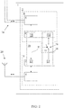
- Fig. 2 shows in an abstract schematic representation a second embodiment of the electrical device 1, the electrical device 1 being designed as an interface device in this embodiment.
- the electrical device 1 has the functional device 2.
- the functional device 2 for its part has the first interface device 4 for secure communication, the second interface device 5 for insecure communication, the first microcontroller 6 and the second microcontroller 7.
- the functional device 2 is divided into the safe function block 8 and the unsafe function block 9.
- the first interface device 4 and the first microcontroller 6 are arranged in the secure function block 8 and the second interface device 5 and the second microcontroller 7, on the other hand, are arranged in the insecure function block 9.
- the functional device 2 only has the second transmission device 15, the second transmission device 15 being able to be activated and deactivated and the functional device 2 being designed to activate and deactivate the second transmission device 15.
- the first transmission device 10 is designed to transmit first signals exclusively from the secure function block 8 via the electrical first signal path 11 to the insecure function block 9 and the second transmission device 15 is designed to transmit second signals exclusively from the insecure function block 9 via the electrical second signal path 16 to the safe function block 8 is formed.
- the first transmission device 10 has the first signal source 12 for the exclusive generation of the first signals and the first signal sink 13 for the exclusive reception of the first signals.
- the second transmission device 15 has in addition to second signal path 16, the second signal source 17 for the exclusive generation of the second signals and the second signal sink 18 for the exclusive reception of the second signals.
- the functional device 2 has the electrical switch 19, which is arranged in the second signal path 16 and in the safe function block 8.
- the switch 19 is activated and deactivated during operation of the electrical device 1 by the first microcontroller 6 of the functional device 2, for which the first microcontroller 6 is set up accordingly.
- the first microcontroller 6 controls the switch 19 in such a way that the switch 19 is open, the second signal path 16 is interrupted and the second transmission device 15 is thus deactivated.
- the first microcontroller 6 controls the switch 19 in such a way that the switch 19 is closed, the second signal path 16 is uninterrupted and the second transmission device 15 is thus activated.
- the first signal source 12 and the second signal sink 18 are implemented in the first microcontroller 6 and thus in the safe function block 8 and the first signal sink 13 and the second signal source 17 are implemented in the second microcontroller 7 and thus in the insecure function block 9.
- the first microcontroller 6 and the second microcontroller 7 are set up in such a way that the first signal source 12 and the first signal sink 13 correspond to a UART (Universal Asynchronous Receiver Transmitter), in which the first signals exclusively from the safe function block 8 via the first signal path 11 to the unsafe function block 9 are transmitted.
- UART Universal Asynchronous Receiver Transmitter
- the first microcontroller 6 and the second microcontroller 7 are set up in such a way that the second signal source 17 and the second signal sink 18 correspond to a UART (Universal Asynchronous Receiver Transmitter), in which the second signals exclusively from the insecure function block 9 via the second signal path 16 to the insecure one Function block 8 are transmitted when switch 19 is closed.
- UART Universal Asynchronous Receiver Transmitter
- the first interface device 4 and the second interface device 5 are designed for simultaneous secure communication and unsecure communication.
- the secure communication takes place exclusively via the first interface device 4 and the insecure communication exclusively via the second interface device 5.
- the conductor-based transmission medium 14 is a bus with two conductors to which only the first interface device 4 is electrically connected.
- Via the first interface device 4 for example communicates bidirectionally according to HART with a process control system.
- the second interface device 5 has a radio module 20 and also communicates bidirectionally with a remote station in accordance with WLAN.
- the electrical device 1 designed as an interface device ensures through the division into a secure function block 8 and an insecure function block 9 and the described transmission of first signals and second signals between the secure function block 8 and the insecure function block 9 that the connected to the first interface device 4
- Process control system such as the measuring device 3 from the first exemplary embodiment is assigned to the safe function block 8. This results in the same advantages as with the measuring device 3.
- the communication via the first interface 4 and the second interface 5 can be implemented according to different standards. These standards include standards for fieldbuses (HART, CAN, Foundation Fieldbus, Profibus), standards for radio transmission (WLAN, Bluetooth, Zigbee, wireless HART), standards for wired interfaces (Ethernet, EtherCAT) and other standards such as LIN, SPI UART, Current interface (4 mA to 20 mA).
- the first interface device 4 and the second interface device 5 are designed for simultaneous secure communication and unsecure communication.
- the secure communication takes place exclusively via the first interface device 4 and the insecure communication exclusively via the second interface device 5.
- the conductor-based transmission medium 14 is a bus with two conductors to which only the first interface device 4 is electrically connected.
- the first interface device 4 is used for bidirectional communication in accordance with HART with a process control system, for example.
- the second interface device 5 has a radio module 20 and also communicates bidirectionally with a remote station in accordance with WLAN.
- the electrical device 1 designed as an interface device ensures through the division into a secure function block 8 and an insecure function block 9 and the described transmission of first signals and second signals between the secure function block 8 and the insecure function block 9 that the connected to the first interface device 4
- Process control system such as the measuring device 3 from the first exemplary embodiment is assigned to the safe function block 8. This results in the same advantages as with the measuring device 3.
- the communication via the first interface 4 and the second interface 5 can be implemented according to different standards. These standards include standards for fieldbuses (HART, CAN, Foundation Fieldbus, Profibus), standards for radio transmission (WLAN, Bluetooth, Zigbee, wireless HART), standards for wired interfaces (Ethernet, EtherCAT) and other standards such as LIN, SPI UART, Current interface (4 mA to 20 mA).
Claims (11)
- Appareil électrique (1) comprenant un dispositif fonctionnel (2),
le dispositif fonctionnel (2) comportant un premier dispositif d'interface (4) destiné à une communication sécurisée et un deuxième dispositif d'interface (5) destiné à une communication non sécurisée,
caractérisé en ce que
le dispositif fonctionnel (2) est divisé en un bloc fonctionnel sécurisé (8) et un bloc fonctionnel non sécurisé (9) et, en plus d'un premier dispositif de transmission (10), il ne comporte plus qu'un deuxième dispositif de transmission (15),
le premier dispositif d'interface (4) est disposé dans le bloc fonctionnel sécurisé (8) et le deuxième dispositif d'interface (5) est disposé dans le bloc fonctionnel non sécurisé (9),
le premier dispositif de transmission (10) est conçu pour la transmission de premiers signaux exclusivement du bloc fonctionnel sécurisé (8) au bloc fonctionnel non sécurisé (9) par le biais d'un premier chemin de signal (11) et le deuxième dispositif de transmission (15) est conçu pour la transmission de deuxièmes signaux exclusivement du bloc fonctionnel non sécurisé (9) au bloc fonctionnel sécurisé (8) par le biais d'un deuxième chemin de signal (16),
le deuxième dispositif de transmission (15) peut être activé et désactivé et
le dispositif fonctionnel (2) du bloc fonctionnel sécurisé (8) est conçu pour activer et désactiver le deuxième dispositif de transmission (15). - Appareil électrique (1) selon la revendication 1, caractérisé en ce que le dispositif fonctionnel (2) du bloc fonctionnel non sécurisé (9) est conçu pour activer et désactiver le deuxième dispositif de transmission (15).
- Appareil électrique (1) selon la revendication 1 ou 2, caractérisé en ce que
le premier dispositif de transmission (10) comporte une première source de signal (12) destinée à la génération exclusive des premiers signaux et un premier récepteur de signal (13) destiné à la réception exclusive des premiers signaux, la première source de signal (12) étant disposée dans le bloc de fonction sécurisé (8) et le premier récepteur de signal (13) étant disposé dans le bloc fonctionnel non sécurisé (9), et
le deuxième dispositif de transmission (15) comporte une deuxième source de signaux (17) destinée à la génération exclusive des deuxièmes signaux et un deuxième récepteur de signaux (18) destiné à la réception exclusive des deuxièmes signaux, la deuxième source de signal (17) étant disposée dans le bloc fonctionnel non sécurisé (9) et le deuxième récepteur de signal (18) étant disposé dans le bloc fonctionnel sécurisé (8). - Appareil électrique (1) selon la revendication 3, caractérisé en ce que la première source de signal (12) et/ou le deuxième récepteur de signal (18) sont mis en œuvre par au moins un premier microcontrôleur (6) et/ou en ce que la deuxième source de signal (17) et/ou le premier récepteur de signal (13) sont mis en œuvre par au moins un deuxième microcontrôleur (7).
- Appareil électrique (1) selon l'une des revendications 1 à 4, caractérisé en ce que le deuxième dispositif de transmission (15) peut être activé et désactivé par un commutateur (19) situé dans le deuxième chemin de signal (16).
- Appareil électrique (1) selon l'une des revendications 1 à 5, caractérisé en ce que le deuxième dispositif de transmission (15) peut être activé et désactivé par activation ou désactivation de la deuxième source de signal (17) et/ou du deuxième récepteur de signal (18).
- Appareil électrique (1) selon l'une des revendications 1 à 6, caractérisé en ce que l'appareil électrique (1) est un appareil de terrain.
- Appareil électrique (1) selon l'une des revendications 1 à 7, caractérisé en ce que l'appareil électrique (1) comporte un dispositif de mesure (3) et le dispositif de mesure (3) est associé au bloc fonctionnel sécurisé (8).
- Appareil électrique (1) selon l'une des revendications 1 à 8, caractérisé en ce que le premier dispositif d'interface (4) et le deuxième dispositif d'interface (5) sont conçus pour être connecté au même milieu de transmission guidé (14) et pour effectuer simultanément une communication sécurisée et une communication non sécurisée.
- Appareil électrique (1) selon l'une des revendications 1 à 9, caractérisé en ce que le premier dispositif d'interface (4) est conçu exclusivement pour effectuer une communication sécurisée unidirectionnelle à partir du premier dispositif d'interface (4).
- Appareil électrique (1) selon l'une des revendications 1 à 10, caractérisé en ce que le deuxième dispositif d'interface (5) est conçu pour effectuer une communication non sécurisée bidirectionnelle.
Applications Claiming Priority (2)
| Application Number | Priority Date | Filing Date | Title |
|---|---|---|---|
| DE102016108062 | 2016-04-30 | ||
| DE102016116152.7A DE102016116152A1 (de) | 2016-04-30 | 2016-08-30 | Elektrisches Gerät mit einer Funktionseinrichtung |
Publications (2)
| Publication Number | Publication Date |
|---|---|
| EP3244274A1 EP3244274A1 (fr) | 2017-11-15 |
| EP3244274B1 true EP3244274B1 (fr) | 2021-01-27 |
Family
ID=58701374
Family Applications (1)
| Application Number | Title | Priority Date | Filing Date |
|---|---|---|---|
| EP17165854.5A Active EP3244274B1 (fr) | 2016-04-30 | 2017-04-11 | Appareil électrique doté d'une unite fonctionnelle |
Country Status (1)
| Country | Link |
|---|---|
| EP (1) | EP3244274B1 (fr) |
Families Citing this family (2)
| Publication number | Priority date | Publication date | Assignee | Title |
|---|---|---|---|---|
| DE102018100629A1 (de) * | 2018-01-12 | 2019-07-18 | Krohne Messtechnik Gmbh | System mit einem elektrischen Gerät |
| DE102018119411A1 (de) * | 2018-08-09 | 2020-02-13 | Endress+Hauser Process Solutions Ag | Feldgerät der Automatisierungstechnik |
Family Cites Families (3)
| Publication number | Priority date | Publication date | Assignee | Title |
|---|---|---|---|---|
| US9305189B2 (en) * | 2009-04-14 | 2016-04-05 | Owl Computing Technologies, Inc. | Ruggedized, compact and integrated one-way controlled interface to enforce confidentiality of a secure enclave |
| US9473300B2 (en) * | 2011-11-03 | 2016-10-18 | Savannah River Nuclear Solutions, Llc | Authenticated sensor interface device |
| AU2014213772A1 (en) * | 2013-02-08 | 2015-08-20 | Bae Systems Plc | A data processing method and apparatus |
-
2017
- 2017-04-11 EP EP17165854.5A patent/EP3244274B1/fr active Active
Non-Patent Citations (1)
| Title |
|---|
| None * |
Also Published As
| Publication number | Publication date |
|---|---|
| EP3244274A1 (fr) | 2017-11-15 |
Similar Documents
| Publication | Publication Date | Title |
|---|---|---|
| EP2984530B1 (fr) | Appareil d'alimentation d'un transducteur de mesure, système destiné à être utilisé dans les techniques d'automatisation, et procédé d'utilisation dudit système | |
| DE102012014681B4 (de) | Verwendung eines lO-Links zur Anbindung eines Netzgerätes | |
| DE19646219A1 (de) | Schaltung für die Kommunikation externer Geräte mit einer zentralen/dezentralen Datenverarbeitungsanlage über einen Bus | |
| CH702454A1 (de) | Anordnung mit einer übergeordneten Steuereinheit und zumindest einem mit der Steuereinheit verbindbaren intelligenten Feldgerät. | |
| DE102011114077A1 (de) | PLC System | |
| DE102017208833A1 (de) | Moduleinheit | |
| EP3244274B1 (fr) | Appareil électrique doté d'une unite fonctionnelle | |
| DE102016000126A1 (de) | Serielles Bussystem mit Koppelmodulen | |
| DE102016116152A1 (de) | Elektrisches Gerät mit einer Funktionseinrichtung | |
| DE102014001462B4 (de) | Feldbusmodul, Maschinensteuerung und Verfahren zur Parametrierung eines, insbesondere sicherheitsgerichteten, Feldbusmoduls | |
| DE102014006148B4 (de) | Endgerät für ein Automatisierungssystem, Endgeräteanordnung sowie Verfahren zum Betreiben eines Endgeräts für ein Automatisierungssystem | |
| EP2701019B1 (fr) | Procédé de paramétrage d'un appareil de terrain, appareil de terrain correspondant et système de paramétrage | |
| EP3133447B1 (fr) | Commutateur de securite | |
| DE19710137B4 (de) | Verfahren und Vorrichtung zur Erweiterung der räumlichen Ausdehnung bei Sensor-Aktuator-Bussystemen | |
| DE102014208839B4 (de) | Verfahren zur sicheren Datenübertragung zwischen einer Automatisierungsanlage und einer IT-Komponente | |
| WO2019096629A1 (fr) | Système de communication de la technique de l'automatisation et industrielle ainsi qu'unité d'aiguillage en y pour un tel système de communication | |
| WO1997049017A1 (fr) | Circuit permettant a des appareils exterieurs de communiquer au moyen d'un bus avec un systeme centralise/decentralise de traitement de donnees | |
| EP3056953A1 (fr) | Dispositif de terrain autarcique pour la surveillance à distance d'un système d'automatisation | |
| EP3512177B1 (fr) | Système doté d'un appareil électrique | |
| EP3439245A1 (fr) | Procédé de transmission de données entre un capteur d'angle de rotation et un dispositif de commande de moteur ou une unité d'évaluation | |
| EP2187278A1 (fr) | Connexion de direction d'un appareil de commutation de sécurité | |
| EP2283426B1 (fr) | Procédé et dispositif permettant de corriger des informations transmises sous forme numérique | |
| DE102016119744A1 (de) | Verfahren und System zum Verhindern eines unerwünschten Zugriffs auf ein Feldgerät | |
| EP2685670A1 (fr) | Transpondeur à bus | |
| DE10359898A1 (de) | Verfahren zum Steuern und Überwachen von Maschinen |
Legal Events
| Date | Code | Title | Description |
|---|---|---|---|
| PUAI | Public reference made under article 153(3) epc to a published international application that has entered the european phase |
Free format text: ORIGINAL CODE: 0009012 |
|
| STAA | Information on the status of an ep patent application or granted ep patent |
Free format text: STATUS: THE APPLICATION HAS BEEN PUBLISHED |
|
| AK | Designated contracting states |
Kind code of ref document: A1 Designated state(s): AL AT BE BG CH CY CZ DE DK EE ES FI FR GB GR HR HU IE IS IT LI LT LU LV MC MK MT NL NO PL PT RO RS SE SI SK SM TR |
|
| AX | Request for extension of the european patent |
Extension state: BA ME |
|
| STAA | Information on the status of an ep patent application or granted ep patent |
Free format text: STATUS: REQUEST FOR EXAMINATION WAS MADE |
|
| 17P | Request for examination filed |
Effective date: 20180514 |
|
| RBV | Designated contracting states (corrected) |
Designated state(s): AL AT BE BG CH CY CZ DE DK EE ES FI FR GB GR HR HU IE IS IT LI LT LU LV MC MK MT NL NO PL PT RO RS SE SI SK SM TR |
|
| GRAP | Despatch of communication of intention to grant a patent |
Free format text: ORIGINAL CODE: EPIDOSNIGR1 |
|
| STAA | Information on the status of an ep patent application or granted ep patent |
Free format text: STATUS: GRANT OF PATENT IS INTENDED |
|
| INTG | Intention to grant announced |
Effective date: 20200407 |
|
| GRAJ | Information related to disapproval of communication of intention to grant by the applicant or resumption of examination proceedings by the epo deleted |
Free format text: ORIGINAL CODE: EPIDOSDIGR1 |
|
| STAA | Information on the status of an ep patent application or granted ep patent |
Free format text: STATUS: REQUEST FOR EXAMINATION WAS MADE |
|
| INTC | Intention to grant announced (deleted) | ||
| GRAP | Despatch of communication of intention to grant a patent |
Free format text: ORIGINAL CODE: EPIDOSNIGR1 |
|
| STAA | Information on the status of an ep patent application or granted ep patent |
Free format text: STATUS: GRANT OF PATENT IS INTENDED |
|
| GRAS | Grant fee paid |
Free format text: ORIGINAL CODE: EPIDOSNIGR3 |
|
| INTG | Intention to grant announced |
Effective date: 20200918 |
|
| GRAF | Information related to payment of grant fee modified |
Free format text: ORIGINAL CODE: EPIDOSCIGR3 |
|
| GRAA | (expected) grant |
Free format text: ORIGINAL CODE: 0009210 |
|
| STAA | Information on the status of an ep patent application or granted ep patent |
Free format text: STATUS: THE PATENT HAS BEEN GRANTED |
|
| AK | Designated contracting states |
Kind code of ref document: B1 Designated state(s): AL AT BE BG CH CY CZ DE DK EE ES FI FR GB GR HR HU IE IS IT LI LT LU LV MC MK MT NL NO PL PT RO RS SE SI SK SM TR |
|
| REG | Reference to a national code |
Ref country code: GB Ref legal event code: FG4D Free format text: NOT ENGLISH |
|
| REG | Reference to a national code |
Ref country code: CH Ref legal event code: EP |
|
| REG | Reference to a national code |
Ref country code: AT Ref legal event code: REF Ref document number: 1358931 Country of ref document: AT Kind code of ref document: T Effective date: 20210215 |
|
| REG | Reference to a national code |
Ref country code: IE Ref legal event code: FG4D Free format text: LANGUAGE OF EP DOCUMENT: GERMAN |
|
| REG | Reference to a national code |
Ref country code: DE Ref legal event code: R096 Ref document number: 502017009194 Country of ref document: DE |
|
| REG | Reference to a national code |
Ref country code: NL Ref legal event code: FP |
|
| REG | Reference to a national code |
Ref country code: LT Ref legal event code: MG9D |
|
| PG25 | Lapsed in a contracting state [announced via postgrant information from national office to epo] |
Ref country code: HR Free format text: LAPSE BECAUSE OF FAILURE TO SUBMIT A TRANSLATION OF THE DESCRIPTION OR TO PAY THE FEE WITHIN THE PRESCRIBED TIME-LIMIT Effective date: 20210127 Ref country code: GR Free format text: LAPSE BECAUSE OF FAILURE TO SUBMIT A TRANSLATION OF THE DESCRIPTION OR TO PAY THE FEE WITHIN THE PRESCRIBED TIME-LIMIT Effective date: 20210428 Ref country code: FI Free format text: LAPSE BECAUSE OF FAILURE TO SUBMIT A TRANSLATION OF THE DESCRIPTION OR TO PAY THE FEE WITHIN THE PRESCRIBED TIME-LIMIT Effective date: 20210127 Ref country code: PT Free format text: LAPSE BECAUSE OF FAILURE TO SUBMIT A TRANSLATION OF THE DESCRIPTION OR TO PAY THE FEE WITHIN THE PRESCRIBED TIME-LIMIT Effective date: 20210527 Ref country code: NO Free format text: LAPSE BECAUSE OF FAILURE TO SUBMIT A TRANSLATION OF THE DESCRIPTION OR TO PAY THE FEE WITHIN THE PRESCRIBED TIME-LIMIT Effective date: 20210427 Ref country code: LT Free format text: LAPSE BECAUSE OF FAILURE TO SUBMIT A TRANSLATION OF THE DESCRIPTION OR TO PAY THE FEE WITHIN THE PRESCRIBED TIME-LIMIT Effective date: 20210127 Ref country code: BG Free format text: LAPSE BECAUSE OF FAILURE TO SUBMIT A TRANSLATION OF THE DESCRIPTION OR TO PAY THE FEE WITHIN THE PRESCRIBED TIME-LIMIT Effective date: 20210427 |
|
| PG25 | Lapsed in a contracting state [announced via postgrant information from national office to epo] |
Ref country code: SE Free format text: LAPSE BECAUSE OF FAILURE TO SUBMIT A TRANSLATION OF THE DESCRIPTION OR TO PAY THE FEE WITHIN THE PRESCRIBED TIME-LIMIT Effective date: 20210127 Ref country code: RS Free format text: LAPSE BECAUSE OF FAILURE TO SUBMIT A TRANSLATION OF THE DESCRIPTION OR TO PAY THE FEE WITHIN THE PRESCRIBED TIME-LIMIT Effective date: 20210127 Ref country code: PL Free format text: LAPSE BECAUSE OF FAILURE TO SUBMIT A TRANSLATION OF THE DESCRIPTION OR TO PAY THE FEE WITHIN THE PRESCRIBED TIME-LIMIT Effective date: 20210127 Ref country code: LV Free format text: LAPSE BECAUSE OF FAILURE TO SUBMIT A TRANSLATION OF THE DESCRIPTION OR TO PAY THE FEE WITHIN THE PRESCRIBED TIME-LIMIT Effective date: 20210127 |
|
| PG25 | Lapsed in a contracting state [announced via postgrant information from national office to epo] |
Ref country code: IS Free format text: LAPSE BECAUSE OF FAILURE TO SUBMIT A TRANSLATION OF THE DESCRIPTION OR TO PAY THE FEE WITHIN THE PRESCRIBED TIME-LIMIT Effective date: 20210527 |
|
| REG | Reference to a national code |
Ref country code: DE Ref legal event code: R097 Ref document number: 502017009194 Country of ref document: DE |
|
| PG25 | Lapsed in a contracting state [announced via postgrant information from national office to epo] |
Ref country code: CZ Free format text: LAPSE BECAUSE OF FAILURE TO SUBMIT A TRANSLATION OF THE DESCRIPTION OR TO PAY THE FEE WITHIN THE PRESCRIBED TIME-LIMIT Effective date: 20210127 Ref country code: EE Free format text: LAPSE BECAUSE OF FAILURE TO SUBMIT A TRANSLATION OF THE DESCRIPTION OR TO PAY THE FEE WITHIN THE PRESCRIBED TIME-LIMIT Effective date: 20210127 Ref country code: SM Free format text: LAPSE BECAUSE OF FAILURE TO SUBMIT A TRANSLATION OF THE DESCRIPTION OR TO PAY THE FEE WITHIN THE PRESCRIBED TIME-LIMIT Effective date: 20210127 |
|
| PG25 | Lapsed in a contracting state [announced via postgrant information from national office to epo] |
Ref country code: DK Free format text: LAPSE BECAUSE OF FAILURE TO SUBMIT A TRANSLATION OF THE DESCRIPTION OR TO PAY THE FEE WITHIN THE PRESCRIBED TIME-LIMIT Effective date: 20210127 Ref country code: MC Free format text: LAPSE BECAUSE OF FAILURE TO SUBMIT A TRANSLATION OF THE DESCRIPTION OR TO PAY THE FEE WITHIN THE PRESCRIBED TIME-LIMIT Effective date: 20210127 Ref country code: SK Free format text: LAPSE BECAUSE OF FAILURE TO SUBMIT A TRANSLATION OF THE DESCRIPTION OR TO PAY THE FEE WITHIN THE PRESCRIBED TIME-LIMIT Effective date: 20210127 Ref country code: RO Free format text: LAPSE BECAUSE OF FAILURE TO SUBMIT A TRANSLATION OF THE DESCRIPTION OR TO PAY THE FEE WITHIN THE PRESCRIBED TIME-LIMIT Effective date: 20210127 |
|
| PLBE | No opposition filed within time limit |
Free format text: ORIGINAL CODE: 0009261 |
|
| STAA | Information on the status of an ep patent application or granted ep patent |
Free format text: STATUS: NO OPPOSITION FILED WITHIN TIME LIMIT |
|
| PG25 | Lapsed in a contracting state [announced via postgrant information from national office to epo] |
Ref country code: LU Free format text: LAPSE BECAUSE OF NON-PAYMENT OF DUE FEES Effective date: 20210411 |
|
| 26N | No opposition filed |
Effective date: 20211028 |
|
| REG | Reference to a national code |
Ref country code: BE Ref legal event code: MM Effective date: 20210430 |
|
| PG25 | Lapsed in a contracting state [announced via postgrant information from national office to epo] |
Ref country code: ES Free format text: LAPSE BECAUSE OF FAILURE TO SUBMIT A TRANSLATION OF THE DESCRIPTION OR TO PAY THE FEE WITHIN THE PRESCRIBED TIME-LIMIT Effective date: 20210127 Ref country code: AL Free format text: LAPSE BECAUSE OF FAILURE TO SUBMIT A TRANSLATION OF THE DESCRIPTION OR TO PAY THE FEE WITHIN THE PRESCRIBED TIME-LIMIT Effective date: 20210127 |
|
| PG25 | Lapsed in a contracting state [announced via postgrant information from national office to epo] |
Ref country code: SI Free format text: LAPSE BECAUSE OF FAILURE TO SUBMIT A TRANSLATION OF THE DESCRIPTION OR TO PAY THE FEE WITHIN THE PRESCRIBED TIME-LIMIT Effective date: 20210127 |
|
| PG25 | Lapsed in a contracting state [announced via postgrant information from national office to epo] |
Ref country code: IT Free format text: LAPSE BECAUSE OF FAILURE TO SUBMIT A TRANSLATION OF THE DESCRIPTION OR TO PAY THE FEE WITHIN THE PRESCRIBED TIME-LIMIT Effective date: 20210127 Ref country code: IE Free format text: LAPSE BECAUSE OF NON-PAYMENT OF DUE FEES Effective date: 20210411 |
|
| PG25 | Lapsed in a contracting state [announced via postgrant information from national office to epo] |
Ref country code: IS Free format text: LAPSE BECAUSE OF FAILURE TO SUBMIT A TRANSLATION OF THE DESCRIPTION OR TO PAY THE FEE WITHIN THE PRESCRIBED TIME-LIMIT Effective date: 20210527 |
|
| PG25 | Lapsed in a contracting state [announced via postgrant information from national office to epo] |
Ref country code: BE Free format text: LAPSE BECAUSE OF NON-PAYMENT OF DUE FEES Effective date: 20210430 |
|
| PG25 | Lapsed in a contracting state [announced via postgrant information from national office to epo] |
Ref country code: HU Free format text: LAPSE BECAUSE OF FAILURE TO SUBMIT A TRANSLATION OF THE DESCRIPTION OR TO PAY THE FEE WITHIN THE PRESCRIBED TIME-LIMIT; INVALID AB INITIO Effective date: 20170411 |
|
| REG | Reference to a national code |
Ref country code: AT Ref legal event code: MM01 Ref document number: 1358931 Country of ref document: AT Kind code of ref document: T Effective date: 20220411 |
|
| PG25 | Lapsed in a contracting state [announced via postgrant information from national office to epo] |
Ref country code: CY Free format text: LAPSE BECAUSE OF FAILURE TO SUBMIT A TRANSLATION OF THE DESCRIPTION OR TO PAY THE FEE WITHIN THE PRESCRIBED TIME-LIMIT Effective date: 20210127 |
|
| PGFP | Annual fee paid to national office [announced via postgrant information from national office to epo] |
Ref country code: NL Payment date: 20230419 Year of fee payment: 7 |
|
| P01 | Opt-out of the competence of the unified patent court (upc) registered |
Effective date: 20230607 |
|
| PG25 | Lapsed in a contracting state [announced via postgrant information from national office to epo] |
Ref country code: AT Free format text: LAPSE BECAUSE OF NON-PAYMENT OF DUE FEES Effective date: 20220411 |
|
| PGFP | Annual fee paid to national office [announced via postgrant information from national office to epo] |
Ref country code: FR Payment date: 20230424 Year of fee payment: 7 Ref country code: DE Payment date: 20230620 Year of fee payment: 7 Ref country code: CH Payment date: 20230502 Year of fee payment: 7 |
|
| PGFP | Annual fee paid to national office [announced via postgrant information from national office to epo] |
Ref country code: GB Payment date: 20230419 Year of fee payment: 7 |