EP3244154A2 - Einspritzung in rohre eines rohrbündelwärmetauschers - Google Patents
Einspritzung in rohre eines rohrbündelwärmetauschers Download PDFInfo
- Publication number
- EP3244154A2 EP3244154A2 EP17156954.4A EP17156954A EP3244154A2 EP 3244154 A2 EP3244154 A2 EP 3244154A2 EP 17156954 A EP17156954 A EP 17156954A EP 3244154 A2 EP3244154 A2 EP 3244154A2
- Authority
- EP
- European Patent Office
- Prior art keywords
- injection element
- tube
- heat exchanger
- tube bundle
- fuel
- Prior art date
- Legal status (The legal status is an assumption and is not a legal conclusion. Google has not performed a legal analysis and makes no representation as to the accuracy of the status listed.)
- Granted
Links
Images

Classifications
-
- F—MECHANICAL ENGINEERING; LIGHTING; HEATING; WEAPONS; BLASTING
- F28—HEAT EXCHANGE IN GENERAL
- F28D—HEAT-EXCHANGE APPARATUS, NOT PROVIDED FOR IN ANOTHER SUBCLASS, IN WHICH THE HEAT-EXCHANGE MEDIA DO NOT COME INTO DIRECT CONTACT
- F28D7/00—Heat-exchange apparatus having stationary tubular conduit assemblies for both heat-exchange media, the media being in contact with different sides of a conduit wall
- F28D7/16—Heat-exchange apparatus having stationary tubular conduit assemblies for both heat-exchange media, the media being in contact with different sides of a conduit wall the conduits being arranged in parallel spaced relation
-
- B—PERFORMING OPERATIONS; TRANSPORTING
- B64—AIRCRAFT; AVIATION; COSMONAUTICS
- B64G—COSMONAUTICS; VEHICLES OR EQUIPMENT THEREFOR
- B64G1/00—Cosmonautic vehicles
- B64G1/22—Parts of, or equipment specially adapted for fitting in or to, cosmonautic vehicles
- B64G1/40—Arrangements or adaptations of propulsion systems
- B64G1/402—Propellant tanks; Feeding propellants
-
- F—MECHANICAL ENGINEERING; LIGHTING; HEATING; WEAPONS; BLASTING
- F02—COMBUSTION ENGINES; HOT-GAS OR COMBUSTION-PRODUCT ENGINE PLANTS
- F02K—JET-PROPULSION PLANTS
- F02K9/00—Rocket-engine plants, i.e. plants carrying both fuel and oxidant therefor; Control thereof
- F02K9/08—Rocket-engine plants, i.e. plants carrying both fuel and oxidant therefor; Control thereof using solid propellants
- F02K9/32—Constructional parts; Details not otherwise provided for
- F02K9/40—Cooling arrangements
-
- F—MECHANICAL ENGINEERING; LIGHTING; HEATING; WEAPONS; BLASTING
- F02—COMBUSTION ENGINES; HOT-GAS OR COMBUSTION-PRODUCT ENGINE PLANTS
- F02K—JET-PROPULSION PLANTS
- F02K9/00—Rocket-engine plants, i.e. plants carrying both fuel and oxidant therefor; Control thereof
- F02K9/42—Rocket-engine plants, i.e. plants carrying both fuel and oxidant therefor; Control thereof using liquid or gaseous propellants
- F02K9/44—Feeding propellants
-
- F—MECHANICAL ENGINEERING; LIGHTING; HEATING; WEAPONS; BLASTING
- F25—REFRIGERATION OR COOLING; COMBINED HEATING AND REFRIGERATION SYSTEMS; HEAT PUMP SYSTEMS; MANUFACTURE OR STORAGE OF ICE; LIQUEFACTION SOLIDIFICATION OF GASES
- F25B—REFRIGERATION MACHINES, PLANTS OR SYSTEMS; COMBINED HEATING AND REFRIGERATION SYSTEMS; HEAT PUMP SYSTEMS
- F25B19/00—Machines, plants or systems, using evaporation of a refrigerant but without recovery of the vapour
- F25B19/005—Machines, plants or systems, using evaporation of a refrigerant but without recovery of the vapour the refrigerant being a liquefied gas
-
- F—MECHANICAL ENGINEERING; LIGHTING; HEATING; WEAPONS; BLASTING
- F28—HEAT EXCHANGE IN GENERAL
- F28F—DETAILS OF HEAT-EXCHANGE AND HEAT-TRANSFER APPARATUS, OF GENERAL APPLICATION
- F28F9/00—Casings; Header boxes; Auxiliary supports for elements; Auxiliary members within casings
- F28F9/02—Header boxes; End plates
- F28F9/026—Header boxes; End plates with static flow control means, e.g. with means for uniformly distributing heat exchange media into conduits
- F28F9/0282—Header boxes; End plates with static flow control means, e.g. with means for uniformly distributing heat exchange media into conduits by varying the geometry of conduit ends, e.g. by using inserts or attachments for modifying the pattern of flow at the conduit inlet or outlet
-
- F—MECHANICAL ENGINEERING; LIGHTING; HEATING; WEAPONS; BLASTING
- F28—HEAT EXCHANGE IN GENERAL
- F28F—DETAILS OF HEAT-EXCHANGE AND HEAT-TRANSFER APPARATUS, OF GENERAL APPLICATION
- F28F9/00—Casings; Header boxes; Auxiliary supports for elements; Auxiliary members within casings
- F28F9/02—Header boxes; End plates
- F28F9/04—Arrangements for sealing elements into header boxes or end plates
- F28F9/16—Arrangements for sealing elements into header boxes or end plates by permanent joints, e.g. by rolling
- F28F9/18—Arrangements for sealing elements into header boxes or end plates by permanent joints, e.g. by rolling by welding
- F28F9/182—Arrangements for sealing elements into header boxes or end plates by permanent joints, e.g. by rolling by welding the heat-exchange conduits having ends with a particular shape, e.g. deformed; the heat-exchange conduits or end plates having supplementary joining means, e.g. abutments
-
- F—MECHANICAL ENGINEERING; LIGHTING; HEATING; WEAPONS; BLASTING
- F05—INDEXING SCHEMES RELATING TO ENGINES OR PUMPS IN VARIOUS SUBCLASSES OF CLASSES F01-F04
- F05D—INDEXING SCHEME FOR ASPECTS RELATING TO NON-POSITIVE-DISPLACEMENT MACHINES OR ENGINES, GAS-TURBINES OR JET-PROPULSION PLANTS
- F05D2260/00—Function
- F05D2260/20—Heat transfer, e.g. cooling
-
- F—MECHANICAL ENGINEERING; LIGHTING; HEATING; WEAPONS; BLASTING
- F28—HEAT EXCHANGE IN GENERAL
- F28D—HEAT-EXCHANGE APPARATUS, NOT PROVIDED FOR IN ANOTHER SUBCLASS, IN WHICH THE HEAT-EXCHANGE MEDIA DO NOT COME INTO DIRECT CONTACT
- F28D21/00—Heat-exchange apparatus not covered by any of the groups F28D1/00 - F28D20/00
- F28D2021/0019—Other heat exchangers for particular applications; Heat exchange systems not otherwise provided for
- F28D2021/0021—Other heat exchangers for particular applications; Heat exchange systems not otherwise provided for for aircrafts or cosmonautics
-
- F—MECHANICAL ENGINEERING; LIGHTING; HEATING; WEAPONS; BLASTING
- F28—HEAT EXCHANGE IN GENERAL
- F28D—HEAT-EXCHANGE APPARATUS, NOT PROVIDED FOR IN ANOTHER SUBCLASS, IN WHICH THE HEAT-EXCHANGE MEDIA DO NOT COME INTO DIRECT CONTACT
- F28D21/00—Heat-exchange apparatus not covered by any of the groups F28D1/00 - F28D20/00
- F28D2021/0019—Other heat exchangers for particular applications; Heat exchange systems not otherwise provided for
- F28D2021/0061—Other heat exchangers for particular applications; Heat exchange systems not otherwise provided for for phase-change applications
- F28D2021/0064—Vaporizers, e.g. evaporators
-
- F—MECHANICAL ENGINEERING; LIGHTING; HEATING; WEAPONS; BLASTING
- F28—HEAT EXCHANGE IN GENERAL
- F28D—HEAT-EXCHANGE APPARATUS, NOT PROVIDED FOR IN ANOTHER SUBCLASS, IN WHICH THE HEAT-EXCHANGE MEDIA DO NOT COME INTO DIRECT CONTACT
- F28D21/00—Heat-exchange apparatus not covered by any of the groups F28D1/00 - F28D20/00
- F28D2021/0019—Other heat exchangers for particular applications; Heat exchange systems not otherwise provided for
- F28D2021/0068—Other heat exchangers for particular applications; Heat exchange systems not otherwise provided for for refrigerant cycles
- F28D2021/0071—Evaporators
-
- Y—GENERAL TAGGING OF NEW TECHNOLOGICAL DEVELOPMENTS; GENERAL TAGGING OF CROSS-SECTIONAL TECHNOLOGIES SPANNING OVER SEVERAL SECTIONS OF THE IPC; TECHNICAL SUBJECTS COVERED BY FORMER USPC CROSS-REFERENCE ART COLLECTIONS [XRACs] AND DIGESTS
- Y02—TECHNOLOGIES OR APPLICATIONS FOR MITIGATION OR ADAPTATION AGAINST CLIMATE CHANGE
- Y02T—CLIMATE CHANGE MITIGATION TECHNOLOGIES RELATED TO TRANSPORTATION
- Y02T10/00—Road transport of goods or passengers
- Y02T10/10—Internal combustion engine [ICE] based vehicles
- Y02T10/30—Use of alternative fuels, e.g. biofuels
Definitions
- the present invention relates to an injection element for a shell and tube heat exchanger, a shell and tube heat exchanger with an injection element, a fuel supply system for a jet engine and a method for cooling fuel for an engine.
- Tube bundle heat exchangers serve to transfer heat between a warmer and a colder fluid, a first of which is passed through a tube bundle with a plurality of tubes, while the second fluid flows around the plurality of tubes.
- These tubes are arranged inside an outer tube and at least partially made of a material with high thermal conductivity.
- tube bundle heat exchangers can be used for cooling in that the first fluid is colder than the second.
- the first fluid may be subjected to an evaporation process, e.g. by causing a transition from the liquid to the gaseous phase by passing this fluid through an expansion valve or by throttling for pressure reduction below the boiling point of the fluid.
- the gaseous fluid is then again compressed to a liquid in a circuit and then re-evaporated.
- a compressor required for this needs a power supply and also has a weight that can be detrimental in certain applications.
- the entrainment of an additional compressor cooling system can be completely energetic sense.
- a fuel cooling to avoid cavitation and in the sense of a uniform combustion of the fuel may be required.
- part of the fuel is often released into space, thus lowering the temperature of the remaining tank contents.
- the present invention has the object to provide a technique with which the above-mentioned disadvantages can be avoided and in particular enables a low-loss and energy-saving cooling of fuel.
- An injection element according to the invention for a shell-and-tube heat exchanger has a corresponding plurality of passages for dividing a fluid flow into a plurality of fluid flows, which narrow conically in each case toward one side of the injection element; "conical” is used in this document to denote a constriction whose diameter-starting from the other side of the injection element-becomes continuously smaller or smaller in several steps relative to the said side. An exact mathematical cone shape is not mandatory for this.
- Such an injection element according to the invention is preferably positionable or positioned in an inlet region of a tube bundle of the shell-and-tube heat exchanger, so that fluid can be conducted into the tube bundle through the passages in the injection element.
- the majority of passages In this case it preferably corresponds to a number of tubes of the tube bundle, so that the fluid can preferably be introduced or injected in each case through an opening into an associated tube of the tube bundle.
- the side to which the passages taper conically, in such a position preferably faces the tubes of the tube bundle.
- the conical narrowing of the passages allows for accurate control of the pressure and mass flow of a fluid being passed.
- a pressure relief can be effected precisely at the narrowest point on the - in the flow direction - the end of the passage.
- This narrowest point acts as an injection orifice, at which a resulting expansion of the liquefied gas preferably ensures its transition to a gaseous state of aggregation, whereas premature evaporation is prevented by the conical shape.
- the diameter of the passages at their narrowest point is in each case in the range of 0.1 mm to 0.6 mm, more preferably in the range of 0.2 mm to 0.4 mm.
- a variant embodiment is advantageous in which mutually opposite wall sections of the respectively conically narrowing passages converge in a cross-sectional plane at an angle of 20 ° to 50 °, more preferably 25 ° to 40 ° (in the direction of the constriction);
- the cross-sectional plane preferably comprises, in addition to the opposite wall sections, a central axis of the respective passage.
- the angle can thus be measured along opposite lines that lie in a plane with the central axis of the respective passage. With a continuous narrowing along a conical surface, the said angle is therefore the opening angle of the associated cone, with a constriction in steps the angle preferably corresponds to a (calculated) mean continuous constriction.
- an injection element according to the invention is designed as a disk or comprises at least one disk-shaped region, through which or pass through passages.
- Such an injection element is particularly easy to manufacture and use in a tube bundle heat exchanger, for example between an injection dome and the tubes of the tube bundle.
- a disk preferably has a substantially uniform thickness in a range of 1mm to 8mm, more preferably 2mm to 4mm.
- the passages are each rotationally symmetrical. They may be holes in the injection element, which can be made for example by means of a conical drill head or can be. In this case, an intended diameter of the narrowest point (injection aperture) of a passage can be generated over the drilling depth.
- a respective central axis of the passages extends obliquely through the injection element.
- said central axis (corresponding in the case of a rotationally symmetrical shape of the respective passage corresponding to a rotation axis) preferably runs obliquely with respect to a surface of the injection element to which the passages narrow.
- the respective central axis of the passages intersects a flat surface of the injection element at an angle of 75 ° to 87 °; when the injection element is used in the heat exchanger, the inclination of the central axis with respect to the tubes (for example, placed perpendicular to the surface of the injection element) is preferably 3 ° to 15 °.
- Such inclination allows turbulence in a fluid conducted through the injector into the tubes. This can cause a longer residence time of the fluid in the tubes of the tube bundle. It also makes it a smoother Temperature distribution in the fluid flowing through the individual tubes causes when these tubes are flowed around for temperature exchange of a fluid of a different temperature.
- an injection element according to the invention may be adapted to be used in a shell-and-tube heat exchanger for cooling fuel.
- An inventive tube bundle heat exchanger serves to cool fuel for an engine. It has a tube bundle comprising a plurality of tubes for the passage of a cooling flow and an outer tube surrounding the tube bundle at least partially for the passage of the fuel.
- the tube bundle heat exchanger comprises an injection element according to the invention according to one of the embodiments disclosed in this document and a feed line to the injection element. The passages of the injection element each lead from the supply line in one of the tubes of the tube bundle (and narrowed conically in this direction).
- Such a shell-and-tube heat exchanger permits a controlled injection of the cooling flow, in particular a pressure relief and a defined injection quantity precisely at the narrowest point due to the conical constrictions.
- a central axis of the passages extends obliquely through the injection element and a narrowest point of the passages is arranged spaced from a central longitudinal axis of the respective tube. Based on a cross section of a pipe into which the respective passage leads, the narrowest point is thus arranged in each case off-center. As a result, an advantageous turbulence or a swirl in the cooling flow can be generated.
- the tubes of the tube bundle each have an inner diameter D which is 7 to 30 times as large as the diameter of the passages b of the injection element in each case at its narrowest point.
- the tubes have a Inside diameter D, which is in a range of 3.6 mm to 3.8 mm;
- the diameter of the passages at their narrowest point is preferably in the range of 0.1 mm to 0.6 mm, more preferably in the range of 0.2 mm to 0.4 mm.
- the injection element is at least partially formed as a disc, which preferably has a substantially uniform thickness whose value is in a range between half and one and a half times an inner diameter of the tubes of the tube bundle.
- a shell-and-tube heat exchanger is adapted to direct a liquefied gas (which may comprise, for example, liquid hydrogen or liquid oxygen) through the supply line to the injection element and produce a pressure drop to the evaporation pressure level in the injection element.
- a liquefied gas which may comprise, for example, liquid hydrogen or liquid oxygen
- a cooling of the fuel can be effected by generating an evaporation process in the liquefied gas.
- the conical constriction allows a controlled pressure reduction and evaporation at the injection orifice (the narrowest point) of the respective passages.
- the efficiency of the cooling can be improved and in particular an incomplete evaporation can be avoided, which means a disadvantageous energy utilization, especially in the absence of a compression circuit (and thus in a lossy discharge of the partially vaporized fluid).
- the supply line to the injection element can be connected to a pressurized liquefied gas tank.
- the tubes of the tube bundle may lead to a lower pressure environment (using the shell and tube heat exchanger in a rocket, e.g., in space).
- an inventive tube bundle heat exchanger is designed as a pressure vessel.
- the heat exchanger is to do so configured to at least substantially maintain a pressure prevailing in the tank in the outer tube.
- An inventive fuel supply system includes a tank and at least one shell and tube heat exchanger according to one of the embodiments disclosed herein.
- the supply system furthermore comprises at least one line which can lead from the tank to the outer tube of the at least one shell-and-tube heat exchanger and / or that from the outer tube of the at least one shell-and-tube heat exchanger to the engine.
- the tank in this case preferably contains at least a portion of the fuel.
- the at least one line leading from the tank to the feed line (to the injection element) and / or from the tube bundle in an environment of the supply system; this line (s) can serve to guide the cooling flow.
- the tank may in this case preferably contain the fuel (so that the cooling flow can be generated from a part of the fuel) or a separate (possibly other) liquefied gas for generating a cooling flow.
- a method according to the invention serves to cool fuel for an engine.
- the fuel is passed through an outer tube of a tube bundle heat exchanger and a liquefied gas through a supply line to an injection element for a arranged inside the outer tube of the tube bundle heat exchanger tube bundle.
- the fuel or the liquid gas may each comprise, for example, liquid hydrogen and / or liquid oxygen.
- the LPG may comprise a portion of the fuel passed through the outer tube and / or further fuel drained from a (other) tank.
- the evaporation gas in the tube bundle acts as a cooling medium on the fuel in the outer tube.
- the evacuation of the evaporation gas can take place, for example, in an environment of the tube bundle heat exchanger or of a vehicle or missile driven by the engine.
- the cooling takes place according to a method according to the invention outside the earth's atmosphere.
- the removal of the evaporation gas in this case can take place in the vacuum of space.
- the prevailing in the pipe (compared to the pressure in the liquid gas prevailing) reduced pressure, which underlies the pressure relief at the injection element and the resulting evaporation, preferably results from a compound of the respective tube interior with the vacuum, for example, be set by a critical throttle or can be.
- a tube bundle heat exchanger according to the invention can be designed as a countercurrent, direct current or crosscurrent recuperator, that is to set up the fuel to be cooled and the cooling flow (essentially) in opposite directions, in the same direction or in one another (one or more times). passing through crossing directions.
- a method according to the invention may comprise passing the cooling flow through the bypass duct in the same direction as the fuel is directed through the main power line, in the opposite direction or in the direction of the main flow (single or multiple) crossing direction (s).
- An opposite direction of cooling flow and fuel to be cooled causes a particularly advantageous cooling.
- directions can possibly allow a compact and simplified construction of the heat exchanger.
- crossed directions can provide a favorable overall structure and - especially with multiple intersections - a long cycle time, which can ensure a correspondingly good heat exchange.
- converting the liquefied gas into an evaporating gas comprises generating turbulence in the evaporating gas by directing the evaporating gas (preferably in an inlet region into the tubes) onto a respective inner wall of the tubes of the tube bundle.
- This straightening can be effected, in particular, by the fact that, as described above, a respective central axis of the passages leads obliquely through the injection element.
- the above-mentioned angles of preferably 75 ° to 87 ° between the respective central axis and the surface of the injection element, towards which the passages constrict, are advantageous.
- FIG. 1 an exemplary power system 200 for an engine according to the present invention is shown schematically.
- the supply system comprises a tank 210 adapted to contain fuel and an exemplary tube bundle heat exchanger 100 according to the invention.
- the supply system 200 comprises a conduit 220 from the tank to the shell and tube heat exchanger 100.
- fuel contained in the tank may be used for cooling in the tank the tube bundle heat exchanger 100 are guided, where it preferably flows in the flow direction R through an outer tube 120, in which a tube bundle 110 is arranged.
- the illustrated supply system 200 includes a conduit 230 from the shell and tube heat exchanger 120 to the engine, which is configured to pass the introduced fuel after it has cooled.
- the supply system 200 includes the FIG. 1 a conduit 240 which leads to the supply line to an exemplary injection element 10 according to the invention in the tube bundle heat exchanger; the injection element will be described below with reference to FIGS Figures 2 and 3 described in more detail.
- the conduit 240 preferably connects the supply line 130 of the shell-and-tube heat exchanger 100 to a tank of liquefied gas.
- This tank may be the tank 210 (the liquefied gas is then part of the fuel) or another tank which may also be part of the supply system and may possibly contain a liquid gas different from the fuel in the tank 210.
- Via a valve 250 the introduction of liquid gas into the tube bundle heat exchanger 100 can be controlled.
- the supply line 130 to the injection element 10 comprises an injection dome 140, from which liquid gas supplied can pass through the injection element 10 into the tubes of the tube bundle 110.
- the liquefied gas is preferably depressurized at or below the evaporation level.
- the resulting vaporization gas is passed as a cooling flow through the tubes of the tube bundle passed, which include a material with high thermal conductivity (eg metal) and thus allow a temperature exchange with the tube bundle in the outer tube 120 flowing around (and to be cooled) fuel.
- the tubes are held by a plurality of brackets 160, which also serve as baffles for the fuel.
- the tube bundle heat exchanger 100 is formed in the example shown as Gegenstromrekuperator, the cooling flow thus runs in the tubes of the tube bundle the flow direction R of the fuel to be cooled contrary.
- the cooling flow enters an environment of the tube bundle heat exchanger, for example in the vacuum of space;
- the connection to the environment by means of the steam outlet 150 makes it possible to lower the pressure when the liquefied gas enters the tubes of the tube bundle.
- FIG. 2 shows a section of a section of an injection element 10:
- Such injection element is used to divide a liquefied gas (which - as indicated by arrows - is introduced into the injection dome 140) in a plurality of fluid streams, for example in each case in tubes 110a, 110b of a tube bundle 110 in a shell and tube heat exchanger, as in FIG. 1 is shown.
- the tubes are held by a plurality of brackets 160, which at the same time serve as baffles for the fuel, which they thus swirl for improved temperature exchange.
- the injection element 10 comprises in the in FIG. 2 In the example shown, a disc-shaped area through which a plurality of passages 11 leads, which extends to one side of the injection element (in the FIG. 2 : to the left side) conically constrict. At the point the tube bundle 110 facing surface 13 of the injection element, the passages 10 thereby each have a narrowest point 12. At this point, a pressure relief leads to evaporation of at least a portion of the liquefied gas and thus to a reduction in temperature, so that forms an evaporating gas as a cooling stream in the tube bundle (the multiple partial flows in the comprising individual tubes; in the figure these are indicated by the dotted lines).
- the passages 11 each lead slightly obliquely through the injection element 10 and are arranged eccentrically with respect to a cross section of the respective tube into which they lead; the narrowest point 12 is thus arranged at a distance from a central longitudinal axis of the respective tube.
- turbulences or swirls
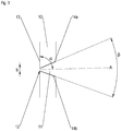
- FIG. 3 are details of an advantageous injection element 10 according to the invention illustrated by the example of a (11 shown in a sectional view):
- the passage 11 has on its surface 13 as an injection orifice at a narrowest point 12, to which it conically narrows.
- an inner diameter D of the tubes is 7 to 30 times greater than a diameter b of the narrowest point 12.
- the diameter b of the narrowest point is in the range of 0.1 mm to 0.6 mm, more preferably in the range of 0.2mm to 0.4mm;
- the inner diameter of the tubes is preferably in a range of 3.6 to 3.8 mm.
- the passage 11 has a central axis A on mutually opposite wall portions 14a, 14b, which lie with the axis A in the cross-sectional plane shown.
- the wall sections run towards each other at an angle ⁇ , which thus represents an opening angle of an underlying cone.
- the angle ⁇ is in a range of 20 ° to 50 °, more preferably 25 ° to 40 °.
- the central axis A extends obliquely through the injection element 10; it extends in particular inclined (not perpendicular) to the surface 13 of the injection element (and thus preferably not parallel to an associated tube of a tube bundle into which the passage 11 preferably opens).
- the intersection angle ⁇ between a flat surface 13 of the injection member and the central axis A is preferably in a range of 75 ° to 87 °. This can - how explained above - advantageous turbulence or an advantageous swirl in a passed cooling stream are generated.
Landscapes
- Engineering & Computer Science (AREA)
- Mechanical Engineering (AREA)
- General Engineering & Computer Science (AREA)
- Physics & Mathematics (AREA)
- Chemical & Material Sciences (AREA)
- Combustion & Propulsion (AREA)
- Thermal Sciences (AREA)
- Remote Sensing (AREA)
- Aviation & Aerospace Engineering (AREA)
- Geometry (AREA)
- Heat-Exchange Devices With Radiators And Conduit Assemblies (AREA)
Abstract
Description
- Die vorliegende Erfindung betrifft ein Einspritzelement für einen Rohrbündelwärmetauscher, einen Rohrbündelwärmetauscher mit einem Einspritzelement, ein Versorgungssystem für eine Triebwerk mit Treibstoff und ein Verfahren zum Kühlen von Treibstoff für ein Triebwerk.
- Rohrbündelwärmetauscher dienen einer Temperaturübertragung zwischen einem wärmeren und einem kälteren Fluid, von denen ein erstes durch ein Rohrbündel mit einer Mehrzahl an Rohren geleitet wird, während das zweite Fluid die Mehrzahl an Rohren umströmt. Diese Rohre sind dazu im Inneren eines Außenrohrs angeordnet und bestehen mindestens teilweise aus einem Material mit hoher Wärmeleitfähigkeit.
- Insbesondere können Rohrbündelwärmetauscher zur Kühlung eingesetzt werden, indem das erste Fluid kälter ist als das zweite. Um dies zu erreichen, kann das erste Fluid einem Verdampfungsprozess unterzogen werden, z.B. indem durch Durchleitung dieses Fluids durch ein Expansionsventil oder durch eine Drosselung zur Druckminderung unter den Siedepunkt des Fluids ein Übergang von der flüssigen in die gasförmige Phase bewirkt wird.
- Beispielsweise in einer Kompressionskältemaschine wird das gasförmige Fluid in einem Kreislauf alsdann wiederum zu einer Flüssigkeit komprimiert und kann dann erneut verdampft werden. Ein dafür nötiger Kompressor benötigt jedoch eine Energiezufuhr und hat zudem ein Gewicht, das in bestimmten Anwendungsbereichen nachteilig sein kann. Beispielsweise in der Flug- oder Weltraumtechnik kann das Mitführen einer zusätzlichen Kompressor-Kühlanlage gesamtenergetisch nicht sinnvoll sein.
- Im Bereich der Raketentechnik kann beispielsweise eine Treibstoffkühlung zur Vermeidung von Kavitationen und im Sinne einer gleichmäßigen Verbrennung des Treibstoffs erforderlich sein. Durch Druckentlastung am Tank selbst wird herkömmlich häufig ein Teil des Treibstoffs ins Weltall abgelassen und so die Temperatur des verbleibenden Tankinhalts gesenkt. Durch den Verzicht auf einen Kreislauf wie oben geschildert geht zwar der abgelassene Treibstoff auf diese Weise verloren, doch es kann auf ein Mitführen eines Kompressors, einer zusätzlichen Stromquelle und eines Kondensators zur Wärmeabstrahlung in den Weltraum verzichtet werden.
- Allerdings erfordert die Druckentlastung eine Wiederbedrückung des Tanks, für die wiederum ein Bedrückungsgas mitgeführt werden muss, was mit energetischem Aufwand verbunden ist.
- Die vorliegende Erfindung hat die Aufgabe, eine Technik bereitzustellen, mit der die oben genannten Nachteile vermieden werden können und die insbesondere eine verlustarme und energiesparende Kühlung von Treibstoff ermöglicht.
- Die Aufgabe wird gelöst durch ein Einspritzelement für einen Rohrbündelwärmetauscher gemäß Anspruch 1, einen Rohrbündelwärmetauscher gemäß Anspruch 5, ein Versorgungssystem für eine Triebwerk mit Treibstoff gemäß Anspruch 7 und ein Verfahren zum Kühlen von Treibstoff für ein Triebwerk gemäß Anspruch 8. Vorteilhafte Ausführungsformen werden in den Unteransprüchen, der Beschreibung und den Figuren offenbart.
- Ein erfindungsgemäßes Einspritzelement für einen Rohrbündelwärmetauscher weist zum Aufteilen eines Fluidstroms in eine Mehrzahl an Fluidströmen eine entsprechende Mehrzahl an Durchlässen auf, die sich zu einer Seite des Einspritzelements hin jeweils kegelartig verengen; als "kegelartig" wird dabei in dieser Schrift eine Verengung bezeichnet, deren Durchmesser - ausgehend von der anderen Seite des Einspritzelements - zu der genannten Seite hin kontinuierlich oder in mehreren Schritten immer kleiner wird. Eine exakte mathematische Kegelform ist dafür nicht zwingend erforderlich.
- Ein derartiges erfindungsgemäßes Einspritzelement ist vorzugsweise in einem Eingangsbereich eines Rohrbündels des Rohrbündelwärmetauschers positionierbar bzw. positioniert, so dass also durch die Durchlässe im Einspritzelement hindurch Fluid in das Rohrbündel geleitet werden kann. Die Mehrzahl an Durchlässen entspricht dabei vorzugsweise einer Anzahl an Rohren des Rohrbündels, so dass das Fluid vorzugsweise jeweils durch einen Durchlass in ein zugehöriges Rohr des Rohrbündels eingeleitet bzw. eingespritzt werden kann. Die Seite, zu der hin sich die Durchlässe kegelartig verengen, ist in einer derartigen Position vorzugsweise den Rohren des Rohrbündels zugewandt. An der engsten Stelle eines jeden Durchlasses tritt ein hindurchgeleitetes Fluid somit vorzugsweise in ein zugehöriges Rohr ein.
- Die kegelartige Verengung der Durchlässe ermöglicht eine genaue Steuerung des Drucks und des Massenstroms eines durchgeleiteten Fluids. Insbesondere kann eine Druckentlastung punktgenau an der jeweils engsten Stelle am - in Durchflussrichtung - Ende des Durchlasses bewirkt werden. Diese engste Stelle wirkt dabei als Einspritzblende, an der eine resultierende Entspannung des Flüssiggases vorzugsweise für dessen Übergang in gasförmigen Aggregatzustand sorgt, wohingegen eine vorzeitige Verdampfung durch die kegelartige Form verhindert wird.
- Insbesondere vorteilhaft sind Ausführungsformen, bei denen der Durchmesser der Durchlässe an ihrer engsten Stelle jeweils im Bereich von 0,1 mm bis 0,6 mm liegt, bevorzugter im Bereich von 0,2 mm bis 0,4 mm.
- Vorteilhaft ist eine Ausführungsvariante, bei der einander gegenüberliegende Wandabschnitte der sich jeweils kegelartig verengenden Durchlässe in einer Querschnittsebene in einem Winkel von 20° bis 50°, bevorzugter von 25° bis 40° (in Richtung der Verengung) aufeinander zulaufen; die Querschnittsebene umfasst dabei vorzugsweise neben den gegenüberliegenden Wandabschnitten eine zentrale Achse des jeweiligen Durchlasses. Der Winkel kann dabei somit entlang gegenüberliegenden Linien gemessen werden, die mit der zentralen Achse des jeweiligen Durchlasses in einer Ebene liegen. Bei kontinuierlicher Verengung entlang einer Kegelmantelfläche ist der besagte Winkel somit der Öffnungswinkel des zugehörigen Kegels, bei einer Verengung in Stufen entspricht der Winkel vorzugsweise einer (berechneten) mittleren kontinuierlichen Verengung.
- Gemäß einer vorteilhaften Ausführungsform ist ein erfindungsgemäßes Einspritzelement als Scheibe ausgebildet oder umfasst zumindest einen scheibenförmigen Bereich, durch die bzw. den hindurch Durchlässe führen. Ein derartiges Einspritzelement lässt sich besonders leicht fertigen und in einen Rohrbündelwärmetauscher einsetzen, beispielsweise zwischen einer Einspritzkuppel und den Rohren des Rohrbündels. Eine derartige Scheibe hat vorzugsweise eine im Wesentlichen gleichmäßige Dicke in einem Bereich von 1mm bis 8mm, bevorzugter von 2mm bis 4mm.
- Vorzugsweise sind die Durchlässe (bzw. ihre Wandungen) jeweils rotationssymmetrisch ausgebildet. Sie können Bohrungen im Einspritzelement sein, die beispielsweise mit Hilfe eines kegelförmigen Bohrerkopfs gefertigt sein bzw. werden können. Dabei kann über die Bohrtiefe ein beabsichtigter vorteilhafter Durchmesser der engsten Stelle (Einspritzblende) eines Durchlasses erzeugt werden.
- Gemäß einer bevorzugten Ausführungsform der vorliegenden Erfindung verläuft eine jeweilige zentrale Achse der Durchlässe jeweils schräg durch das Einspritzelement. Insbesondere verläuft die genannte zentrale Achse (die im Falle einer rotationssymmetrischen Form des jeweiligen Durchlasses entsprechend mit einer Rotationsachse übereinstimmt) vorzugsweise schräg gegenüber einer Oberfläche des Einspritzelements, zu der hin sich die Durchlässe verengen.
- Besonders bevorzugt ist dabei eine Ausführungsform, bei der die jeweilige zentrale Achse der Durchlässe eine ebene Oberfläche des Einspritzelements unter einem Winkel von 75° bis 87° schneidet; bei Verwendung des Einspritzelements im Wärmetauscher ergibt sich vorzugsweise eine Neigung der zentralen Achse gegenüber den (z.B. senkrecht auf die Oberfläche des Einspritzelementes aufsetzenden) Rohren um 3° bis 15°.
- Eine derartige Neigung ermöglicht eine Verwirbelung bzw. einen Drall in einem durch das Einspritzelement in die Rohre geleiteten Fluid. Dies kann eine längere Verweildauer des Fluids in den Rohren des Rohrbündels bewirken. Zudem wird damit eine gleichmäßigere Temperaturverteilung im die einzelnen Rohre durchströmenden Fluid bewirkt, wenn diese Rohre zum Temperaturaustausch von einem Fluid einer anderen Temperatur umströmt werden.
- Insbesondere kann ein erfindungsgemäßes Einspritzelement dazu eingerichtet sein, in einem Rohrbündelwärmetauscher zum Kühlen von Treibstoff verwendet zu werden.
- Ein erfindungsgemäßer Rohrbündelwärmetauscher dient einem Kühlen von Treibstoff für ein Triebwerk. Er weist ein mehrere Rohre umfassendes Rohrbündel zur Durchleitung eines Kühlstroms sowie einen das Rohrbündel mindestens teilweise umgebendes Außenrohr zur Durchleitung des Treibstoffs auf. Zudem umfasst der Rohrbündelwärmetauscher ein erfindungsgemäßes Einspritzelement gemäß einer der in dieser Schrift offenbarten Ausführungsformen sowie eine Zuleitung zum Einspritzelement. Die Durchlässe des Einspritzelements führen jeweils von der Zuleitung in eines der Rohre des Rohrbündels (und verengen sich in dieser Richtung jeweils kegelartig).
- Ein derartiger Rohrbündelwärmetauscher ermöglicht infolge der kegelartigen Verengungen ein kontrolliertes Einspritzen des Kühlstroms, insbesondere eine Druckentlastung und eine definierte Einspritzmenge punktgenau an der jeweils engsten Stelle.
- Gemäß einer bevorzugten Ausführungsform eines erfindungsgemäßen Rohrbündelwärmetauschers verläuft eine zentrale Achse der Durchlässe jeweils schräg durch das Einspritzelement und ist eine engste Stelle der Durchlässe jeweils von einer zentralen Längsachse des jeweiligen Rohrs beabstandet angeordnet. Bezogen auf einen Querschnitt eines Rohrs, in das der jeweilige Durchlass führt, ist die engste Stelle somit jeweils außermittig angeordnet. Dadurch kann eine vorteilhafte Verwirbelung bzw. ein Drall im Kühlstrom erzeugt werden.
- Vorteilhaft ist eine Ausführungsform, bei der die Rohre des Rohrbündels jeweils einen Innendurchmesser D aufweisen, der 7 bis 30 mal so groß ist wie der Durchmesser der Durchlässe b des Einspritzelements jeweils an ihrer engsten Stelle. Gemäß einem speziellen Ausführungsbeispiel weisen die Rohre einen Innendurchmesser D auf, der in einem Bereich von 3,6mm bis 3,8 mm liegt; die Durchmesser der Durchlässe an ihrer engsten Stelle liegt dabei vorzugsweise im Bereich von 0,1 mm bis 0,6 mm, bevorzugter im Bereich von 0,2 mm bis 0,4 mm.
- Gemäß einer vorteilhaften Ausführungsform ist das Einspritzelement mindestens teilweise als Scheibe ausgebildet, das vorzugsweise eine im Wesentlichen gleichmäßige Dicke aufweist, deren Wert in einem Bereich zwischen der Hälfte und dem Anderthalbfachen eines Innendurchmessers der Rohre des Rohrbündels liegt.
- Gemäß einer vorteilhaften Ausführungsform ist ein erfindungsgemäßer Rohrbündelwärmetauscher dazu eingerichtet, ein Flüssiggas (das z.B. Flüssigwasserstoff oder Flüssigsauerstoff umfassen kann) durch die Zuleitung zum Einspritzelement zu leiten und im Einspritzelement eine Druckabsenkung auf Verdampfungsdruckniveau herzustellen.
- Auf diese Weise kann eine Kühlung des Treibstoffs durch Erzeugen eines Verdampfungsprozesses im Flüssiggas bewirkt werden. Die kegelartige Verengung ermöglicht dabei eine kontrollierte Druckreduzierung und Verdampfung an der Einspritzblende (der engsten Stelle) der jeweiligen Durchlässe. So kann die Effizienz der Kühlung verbessert und insbesondere eine unvollständige Verdampfung vermieden werden, die gerade bei einem Verzicht auf einen Kompressionskreislauf (und somit bei einem verlustbehafteten Ablassen des teilverdampften Fluids) eine nachteilige Energieverwertung bedeutet.
- Insbesondere kann bei einem erfindungsgemäßen Rohrbündelwärmetauscher die Zuleitung zum Einspritzelement an einen druckbeaufschlagten Flüssiggastank angeschlossen sein. An ihrem dem Einspritzelement abgewandten Ende können die Rohre des Rohrbündels in eine Umgebung mit niedrigerem Druck führen (bei Verwendung des Rohrbündelwärmetauschers in einer Rakete z.B. in das Weltall).
- Gemäß einer vorteilhaften Ausführungsvariante ist ein erfindungsgemäßer Rohrbündelwärmetauscher als Druckbehälter ausgelegt. Vorzugsweise ist der Wärmetauscher dabei dazu eingerichtet, einen im Tank herrschenden Druck im Außenrohr zumindest im Wesentlichen aufrecht zu erhalten.
- Ein erfindungsgemäßes Versorgungssystem für ein Triebwerk mit Treibstoff umfasst einen Tank und mindestens einen Rohrbündelwärmetauscher gemäß einem der in dieser Schrift offenbarten Ausführungsformen. Das Versorgungssystem umfasst weiterhin mindestens eine Leitung, die vom Tank zum Außenrohr des mindestens einen Rohrbündelwärmetauschers und/oder die vom Außenrohr des mindestens einen Rohrbündelwärmetauschers zum Triebwerk führen kann. Durch eine (oder mehrere) derartige Leitung(en) kann somit der zu kühlende Treibstoff geleitet werden. Der Tank enthält in diesem Fall vorzugsweise mindestens einen Teil des Treibstoffs. Alternativ oder zusätzlich kann die mindestens eine Leitung vom Tank zur Zuleitung (zum Einspritzelement) und/oder vom Rohrbündel in eine Umgebung des Versorgungssystems führen; diese Leitung(en) können dabei dazu dienen, den Kühlstrom zu führen. Der Tank kann in diesem Fall vorzugsweise den Treibstoff enthalten (so dass der Kühlstrom aus einem Teil des Treibstoff generiert werden kann) oder ein separates (ggf. anderes) Flüssiggas zur Erzeugung eines Kühlstroms.
- Ein erfindungsgemäßes Verfahren dient einem Kühlen von Treibstoff für ein Triebwerk. Dabei werden der Treibstoff durch ein Außenrohr eines Rohrbündelwärmetauschers geleitet sowie ein Flüssiggas durch eine Zuleitung bis an ein Einspritzelement für ein im Inneren des Außenrohrs des Rohrbündelwärmetauschers angeordnetes Rohrbündel. Der Treibstoff bzw. das Flüssiggas können jeweils beispielsweise Flüssigwasserstoff und/oder Flüssigsauerstoff umfassen. Das Flüssiggas kann insbesondere einen Teil des durch das Außenrohr geleiteten Treibstoffs und/oder weiteren aus einem (anderen) Tank herausgeleiteten Treibstoff umfassen. Durch Hindurchleiten des Flüssiggases durch sich jeweils kegelartige verengende Durchlässe des Einspritzelements und in Rohre des Rohrbündels hinein wird weiterhin mindestens ein Teil des Flüssiggases in ein Verdampfungsgas umgewandelt, das dann aus dem Rohrbündel abgeführt wird.
- Das Verdampfungsgas im Rohrbündel wirkt dabei als Kühlmedium auf den Treibstoff im Außenrohr. Mit der Durchleitung durch die sich kegelartig verengenden Durchlässe und deren als Einspritzblende wirkende engste Stelle können die Druckentlastung und die Einspritzmenge genau positioniert und damit insbesondere eine vorzeitige und/oder unvollständige Umwandlung und/oder Verteilung des Kühlmediums auf die Rohre verhindert werden.
- Das Abführen des Verdampfungsgases kann beispielsweise in eine Umgebung des Rohrbündelwärmetauschers bzw. eines durch das Triebwerk angetriebenen Fahrzeugs oder Flugkörpers hinein erfolgen.
- Gemäß einer vorteilhaften Ausführungsform erfolgt das Kühlen gemäß einem erfindungsgemäßen Verfahren außerhalb der Erdatmosphäre. Insbesondere kann das Abführen des Verdampfungsgases in diesem Fall in das Vakuum des Weltraums erfolgen. Der im Rohr herrschende (gegenüber dem Druck im Flüssiggas herrschende) reduzierte Druck, der der Druckentlastung am Einspritzelement und der resultierenden Verdampfung zugrunde liegt, ergibt sich vorzugsweise aus einer Verbindung des jeweiligen Rohrinneren mit dem Vakuum, die beispielsweise durch eine kritische Drossel eingestellt sein bzw. werden kann.
- Ein erfindungsgemäßer Rohrbündelwärmetauscher kann gemäß bevorzugten Ausführungsformen als Gegenstrom-, Gleichstrom- oder Kreuzstromrekuperator ausgebildet sein, also dazu eingerichtet, den zu kühlenden Treibstoff und den Kühlstrom (im Wesentlichen) in entgegengesetzten Richtungen, in die gleiche Richtung oder in einander (ein- oder mehrfach) kreuzenden Richtungen durchzuleiten.
- Entsprechend kann ein erfindungsgemäßes Verfahren ein Durchleiten des Kühlstroms durch die Nebenstromleitung in dieselbe Richtung umfassen, in die der Treibstoff durch die Hauptstromleitung geleitet wird, in dazu entgegengesetzte Richtung oder in die Hauptstromrichtung (ein- oder mehrfach) kreuzende Richtung(en).
- Eine entgegengesetzte Richtung von Kühlstrom und zu kühlendem Treibstoff bewirkt eine besonders vorteilhafte Kühlung. Gleiche Richtungen dagegen können ggf. einen kompakten und vereinfachten Aufbau des Wärmetauschers ermöglichen. Analog können gekreuzte Richtungen einen vorteilhaften Gesamtaufbau und - gerade bei Mehrfachkreuzung - eine große Durchlaufdauer ermöglichen, was einen entsprechend guten Wärmeaustausch gewährleisten kann.
- Gemäß einer vorteilhaften Ausführungsform eines erfindungsgemäßen Verfahrens umfasst das Umwandeln des Flüssiggases in ein Verdampfungsgas ein Erzeugen von Verwirbelungen bzw. Drall im Verdampfungsgas, indem das Verdampfungsgas (vorzugsweise in einem Eintrittsbereich in die Rohre) auf eine jeweilige Innenwand der Rohre des Rohrbündels gerichtet wird. Dieses Richten kann insbesondere dadurch bewirkt werden, dass - wie oben beschrieben - eine jeweilige zentrale Achse der Durchlässe jeweils schräg durch das Einspritzelement führt. Vorteilhaft sind dabei die oben genannten Winkel von vorzugsweise 75° bis 87° zwischen der jeweiligen zentralen Achse und der Oberfläche des Einspritzelements, zu der hin sich die Durchlässe verengen.
- Im Folgenden werden bevorzugte Ausführungsbeispiele der Erfindung anhand von Zeichnungen näher erläutert. Es versteht sich, dass einzelne Elemente und Komponenten auch anders kombiniert werden können als dargestellt. Bezugszeichen für einander entsprechende Elemente sind figurenübergreifend verwendet und werden ggf. nicht für jede Figur neu beschrieben.
- Es zeigen schematisch:
- Figur 1:
- ein erfindungsgemäßes Versorgungssystem mit Rohrbündelwärmetauscher gemäß einer Ausführungsform der vorliegenden Erfindung in einem Querschnitt;
- Figur 2:
- eine Detailansicht eines Abschnitts eines erfindungsgemäßen Rohrbündelwärmetauschers mit Einspritzelement; und
- Figur 3:
- eine Detailansicht eines Durchlasses eines erfindungsgemäßen Einspritzelements.
- In
Figur 1 ist ein exemplarisches Versorgungssystem 200 für ein Triebwerk gemäß der vorliegenden Erfindung schematisch dargestellt. Das Versorgungssystem umfasst einen Tank 210, der dazu eingerichtet ist, Treibstoff zu enthalten, sowie einen exemplarischen erfindungsgemäßen Rohrbündelwärmetauscher 100. Zudem umfasst das Versorgungssystem 200 eine Leitung 220 vom Tank zum Rohrbündelwärmetauscher 100. Mittels der Leitung 220 kann vorzugsweise im Tank enthaltener Treibstoff zur Kühlung in den Rohrbündelwärmetauscher 100 geführt werden, wo es vorzugsweise in der Durchflussrichtung R durch ein Außenrohr 120 strömt, in dem ein Rohrbündel 110 angeordnet ist. - Weiterhin umfasst das gezeigte Versorgungssystem 200 eine Leitung 230 vom Rohrbündelwärmetauscher 120 zum Triebwerk, die dazu eingerichtet ist, den eingeleiteten Treibstoff nach seiner Kühlung weiterzuleiten.
- Schließlich umfasst das Versorgungssystem 200 der
Figur 1 eine Leitung 240, die zur Zuleitung zu einem exemplarischen erfindungsgemäßen Einspritzelement 10 im Rohrbündelwärmetauscher führt; das Einspritzelement wird weiter unten mit Bezug zu denFiguren 2 und3 näher beschrieben. - Die Leitung 240 verbindet vorzugsweise die Zuleitung 130 des Rohrbündelwärmetauschers 100 mit einem Tank mit Flüssiggas. Dieser Tank kann der Tank 210 sein (das Flüssiggas ist dann also ein Teil des Treibstoffs) oder ein anderer Tank, der ebenfalls Teil des Versorgungssystems sein kann und ggf. ein vom Treibstoff im Tank 210 verschiedenes Flüssiggas enthalten kann. Über ein Ventil 250 kann das Einleiten von Flüssiggas in den Rohrbündelwärmetauscher 100 gesteuert werden.
- Die Zuleitung 130 zum Einspritzelement 10 umfasst eine Einspritzkuppel 140, von der aus zugeleitetes Flüssiggas durch das Einspritzelement 10 in die Rohre des Rohrbündels 110 gelangen kann. Dabei wird das Flüssiggas vorzugsweise auf oder unterhalb Verdampfungsniveau druckentlastet. Das entstehende Verdampfungsgas wird als Kühlstrom durch die Rohre des Rohrbündels hindurch geleitet, die ein Material mit hoher Wärmeleitfähigkeit umfassen (z.B. Metall) und so einen Temperaturaustausch mit einem das Rohrbündel im Außenrohr 120 umströmenden (und zu kühlenden) Treibstoff ermöglichen. Die Rohre werden dabei durch eine Mehrzahl an Halterungen 160 gehalten, die zugleich als Prallbleche für den Treibstoff dienen. Der Rohrbündelwärmetauscher 100 ist im gezeigten Beispiel als Gegenstromrekuperator ausgebildet, der Kühlstrom läuft also in den Rohren des Rohrbündels der Durchflussrichtung R des zu kühlenden Treibstoffs entgegen.
- Durch einen Dampfauslass 150 gelangt der Kühlstrom in eine Umgebung des Rohrbündelwärmetauschers, beispielsweise in das Vakuum des Weltraums; in diesem Fall ermöglicht insbesondere die mittels des Dampfauslasses 150 bestehende Verbindung zur Umgebung das Absenken des Drucks beim Eintritt des Flüssiggases in die Rohre des Rohrbündels.
-
Figur 2 zeigt in einer Schnittdarstellung einen Ausschnitt eines Einspritzelements 10: Ein derartiges Einspritzelement dient einem Aufteilen eines Flüssiggases (das - wie durch Pfeile gekennzeichnet - in die Einspritzkuppel 140 eingeleitet wird) in eine Mehrzahl an Fluidströmen, beispielsweise jeweils in Rohren 110a, 110b eines Rohrbündels 110 in einem Rohrbündelwärmetauscher, wie er inFigur 1 gezeigt ist. Wie oben erwähnt werden die Rohre durch eine Mehrzahl an Halterungen 160 gehalten, die zugleich als Prallbleche für den Treibstoff dienen, den sie somit für einen verbesserten Temperaturaustausch verwirbeln. - Das Einspritzelement 10 umfasst im in der
Figur 2 gezeigten Beispiel einen scheibenförmigen Bereich, durch den hindurch eine Mehrzahl an Durchlässen 11 führt, die sich zu einer Seite des Einspritzelements (in derFigur 2 : zur linken Seite) hin jeweils kegelartig verengen. An der dem Rohrbündel 110 zugewandten Oberfläche 13 des Einspritzelements haben die Durchlässe 10 dadurch jeweils eine engste Stelle 12. An dieser Stelle führt eine Druckentlastung zur Verdampfung mindestens eines Teils des Flüssiggases und damit zu einer Temperaturverringerung, so dass sich im Rohrbündel ein Verdampfungsgas als Kühlstrom bildet (der mehrere Teilströme in den einzelnen Rohren umfasst; in der Figur sind diese durch die gepunkteten Linien angedeutet). - Die Durchlässe 11 führen jeweils leicht schräg durch das Einspritzelement 10 und sind gegenüber einem Querschnitt des jeweiligen Rohrs, in das sie führen, außermittig angeordnet; die engste Stelle 12 ist somit von einer zentralen Längsachse des jeweiligen Rohrs beabstandet angeordnet. So bilden sich - wie in der Figur angedeutet - Verwirbelungen (bzw. Drall) im Kühlstrom, die einen Kühleffekt verbessern.
- In der
Figur 3 sind am Beispiel eines (in einer Schnittdarstellung gezeigten) Durchlasses 11 Einzelheiten eines vorteilhaften erfindungsgemäßen Einspritzelements 10 verdeutlicht: Der Durchlass 11 weist an seiner Oberfläche 13 als Einspritzblende eine engste Stelle 12 auf, zu der hin er sich kegelartig verengt. Vorteilhaft ist eine Ausführungsform, bei der ein Innendurchmesser D der Rohre 7 bis 30 mal so groß ist wie ein Durchmesser b der engsten Stelle 12. Gemäß einem speziellen Ausführungsbeispiel liegt der Durchmesser b der engsten Stelle im Bereich von 0,1 mm bis 0,6 mm liegt, bevorzugter im Bereich von 0,2mm bis 0,4mm; der Innendurchmesser der Rohre liegt dabei vorzugsweise in einem Bereich von 3,6 bis 3,8 mm. - Der Durchlass 11 weist eine zentrale Achse A auf einander gegenüberliegende Wandabschnitte 14a, 14b auf, die mit der Achse A in der gezeigten Querschnittsebene liegen. Die Wandabschnitte laufen dabei in einem Winkel β aufeinander zu, der somit einen Öffnungswinkel eines zugrundeliegenden Kegels darstellt. Vorzugsweise liegt der Winkel β in einem Bereich von 20° bis 50°, bevorzugter von 25° bis 40°.
- Die zentrale Achse A verläuft schräg durch das Einspritzelement 10; sie verläuft insbesondere geneigt (nicht senkrecht) zur Oberfläche 13 des Einspritzelements (und damit vorzugsweise nicht parallel zu einem zugeordneten Rohr eines Rohrbündels, in das der Durchlass 11 vorzugsweise mündet). Der Schnittwinkel α zwischen einer ebenen Oberfläche 13 des Einspritzelements und der zentralen Achse A liegt vorzugsweise in einem Bereich von 75° bis 87°. Dadurch können - wie oben erläutert - vorteilhafte Verwirbelungen bzw. ein vorteilhafter Drall in einem hindurchgeleiteten Kühlstrom erzeugt werden.
-
- 10 Einspritzelement
- 11 Durchlass
- 12 engste Stelle (Einspritzblende)
- 13 Oberfläche des Einspritzelements
- 14a, 14b Wandabschnitte des Durchlasses
- 100 Rohrbündelwärmetauscher
- 110 Rohrbündel
- 110a, 110b Rohr des Rohrbündels
- 120 Außenrohr
- 130 Zuleitung zum Einspritzelement
- 140 Einspritzkuppel
- 150 Dampfauslass
- 160 Halterung und Prallblech
- 200 Versorgungssystem
- 210 Tank
- 220 Leitung vom Tank zum Rohrbündelwärmetauscher
- 230 Leitung vom Rohrbündelwärmetauscher zum Triebwerk
- 240 Leitung zur Zuleitung zum Einspritzelement
- 250 Ventil
- A zentrale Achse eines Durchlasses
- b Durchmesser der Einspritzblende
- R Durchflussrichtung
- α Neigungswinkel der zentralen Achse zur Oberfläche des Einspritzelements
- β Winkel zwischen Wandabschnitten eines Durchlasses
Claims (10)
- Einspritzelement (10) für einen Rohrbündelwärmetauscher, das zum Aufteilen eines Fluidstroms in eine Mehrzahl an Fluidströmen eine Mehrzahl an Durchlässen (11) aufweist, die sich zu einer Seite des Einspritzelements hin jeweils kegelartig verengen.
- Einspritzelement gemäß Anspruch 1, das zumindest einen scheibenförmigen Bereich umfasst, durch den hindurch die Durchlässe (11) führen.
- Einspritzelement gemäß einem der Ansprüche 1 oder 2, wobei die Durchlässe an ihrer engsten Stelle (12) jeweils einen Durchmesser (b) im Bereich von 0,1 mm bis 0,6 mm haben, bevorzugter im Bereich von 0,2mm bis 0,4mm.
und/oder wobei gegenüberliegende Wandabschnitte (14a, 14b) der sich jeweils kegelartig verengenden Durchlässe in einer Querschnittsebene in einem Winkel (β) von 20° bis 50°, bevorzugter von 25° bis 40° aufeinander zulaufen. - Einspritzelement gemäß einem der vorhergehenden Ansprüche, wobei eine jeweilige zentrale Achse (A) der Durchlässe jeweils schräg durch das Einspritzelement (10) verläuft.
- Rohrbündelwärmetauscher (20) zum Kühlen von Treibstoff für ein Triebwerk, wobei der Rohrbündelwärmetauscher aufweist:ein mehrere Rohre (110a, 110b) umfassendes Rohrbündel (110) zur Durchleitung eines Kühlstroms sowie ein das Rohrbündel (110) mindestens teilweise umgebendes Außenrohr (120) zur Durchleitung des Treibstoffs,ein Einspritzelement (10) gemäß einem der vorhergehenden Ansprüche und eine Zuleitung (130) zum Einspritzelement,wobei die Durchlässe (11) des Einspritzelements jeweils von der Zuleitung in eines der Rohre (110a, 110b) des Rohrbündels führen.
- Rohrbündelwärmetauscher gemäß Anspruch 5, der dazu eingerichtet ist, ein Flüssiggas durch die Zuleitung (130) zum Einspritzelement (10) zu leiten und im Einspritzelement eine Druckabsenkung auf oder unterhalb Verdampfungsdruckniveau herzustellen.
- Versorgungssystem (200) für eine Triebwerk mit Treibstoff, das einen Tank (210) und mindestens einen Rohrbündelwärmetauscher (100) gemäß einem der Ansprüche 5 oder 6 umfasst
sowie mindestens eine Leitung
vom Tank zum Außenrohr (120) des mindestens einen Rohrbündelwärmetauschers
und/oder vom Außenrohr (120) des mindestens einen Rohrbündelwärmetauschers zum Triebwerk
und/oder vom Tank zur Zuleitung (130) zum Einspritzelement und/oder vom Rohrbündel (110) in eine Umgebung des Versorgungssystems. - Verfahren zum Kühlen von Treibstoff für ein Triebwerk, wobei das Verfahren umfasst:ein Durchleiten des Treibstoffs durch ein Außenrohr (120) eines Rohrbündelwärmetauschers (100);ein Zuleiten eines Flüssiggases durch eine Zuleitung (130) bis an ein Einspritzelement (10) für ein im Inneren des Außenrohrs (120) angeordnetes ein Rohrbündel (110) des Rohrbündelwärmetauschers;ein Umwandeln mindestens eines Teils des Flüssiggases in ein Verdampfungsgas durch Hindurchleiten des Flüssiggases durch sich jeweils kegelartige verengende Durchlässe (11) des Einspritzelements in Rohre (110a, 110b) des Rohrbündels hinein; undein Abführen des Verdampfungsgases aus dem Rohrbündel.
- Verfahren gemäß Anspruch 8, wobei das Flüssiggas einen Teil des durch das Außenrohr (120) geleiteten Treibstoffs und/oder weiteren aus einem Tank herausgeleiteten Treibstoff umfasst.
- Verfahren gemäß einem der Ansprüche 8 oder 9, wobei das Umwandeln ein Erzeugen von Verwirbelungen und/oder Drall im Verdampfungsgas durch Richten des Verdampfungsgases auf eine jeweilige Innenwand der Rohre (110a,110b) des Rohrbündels umfasst.
Applications Claiming Priority (1)
| Application Number | Priority Date | Filing Date | Title |
|---|---|---|---|
| DE102016103229.8A DE102016103229B4 (de) | 2016-02-24 | 2016-02-24 | Einspritzung in Rohre eines Rohrbündelwärmetauschers |
Publications (3)
| Publication Number | Publication Date |
|---|---|
| EP3244154A2 true EP3244154A2 (de) | 2017-11-15 |
| EP3244154A3 EP3244154A3 (de) | 2018-01-24 |
| EP3244154B1 EP3244154B1 (de) | 2020-04-22 |
Family
ID=58094319
Family Applications (1)
| Application Number | Title | Priority Date | Filing Date |
|---|---|---|---|
| EP17156954.4A Active EP3244154B1 (de) | 2016-02-24 | 2017-02-20 | Einspritzung in rohre eines rohrbündelwärmetauschers |
Country Status (2)
| Country | Link |
|---|---|
| EP (1) | EP3244154B1 (de) |
| DE (1) | DE102016103229B4 (de) |
Cited By (1)
| Publication number | Priority date | Publication date | Assignee | Title |
|---|---|---|---|---|
| CN115151321A (zh) * | 2020-02-25 | 2022-10-04 | 雅苒国际集团 | 用于液流的分配室 |
Family Cites Families (11)
| Publication number | Priority date | Publication date | Assignee | Title |
|---|---|---|---|---|
| GB1196562A (en) * | 1967-02-17 | 1970-07-01 | Hitachi Ltd | Welded Assembly of a Tube and a Tube Sheet |
| GB1288166A (de) * | 1970-02-24 | 1972-09-06 | ||
| DE2502181A1 (de) * | 1975-01-21 | 1976-07-22 | Becker Pruente Gmbh | Verfahren zum verbinden von rohren aus thermoplastischem kunststoff mit plattenboeden aus thermoplastischem kunststoff |
| US4585057A (en) * | 1982-09-30 | 1986-04-29 | Krw Energy Systems Inc. | Cooled tubesheet inlet for abrasive fluid heat exchanger |
| JPH0730213Y2 (ja) | 1988-11-17 | 1995-07-12 | 川崎重工業株式会社 | 熱交換器 |
| GB9604727D0 (en) * | 1996-03-06 | 1996-05-08 | Rover Group | Motor vehicle engine and fuel cooling system |
| KR19980080427A (ko) * | 1997-04-09 | 1998-11-25 | 다카노야스아키 | 흡수식 냉동기 |
| US8381508B2 (en) | 2009-05-28 | 2013-02-26 | Alliant Techsystems Inc. | Closed-cycle rocket engine assemblies and methods of operating such rocket engine assemblies |
| WO2011014059A1 (en) * | 2009-07-30 | 2011-02-03 | Twister B.V. | Tapered throttling valve |
| JP5762093B2 (ja) * | 2011-03-31 | 2015-08-12 | 三菱重工業株式会社 | 航空機・宇宙機用流体冷却システム及び航空機・宇宙機用流体冷却方法 |
| US9200650B2 (en) * | 2013-09-26 | 2015-12-01 | Paul D. Van Buskirk | Orifice plates |
-
2016
- 2016-02-24 DE DE102016103229.8A patent/DE102016103229B4/de active Active
-
2017
- 2017-02-20 EP EP17156954.4A patent/EP3244154B1/de active Active
Non-Patent Citations (1)
| Title |
|---|
| None |
Cited By (3)
| Publication number | Priority date | Publication date | Assignee | Title |
|---|---|---|---|---|
| CN115151321A (zh) * | 2020-02-25 | 2022-10-04 | 雅苒国际集团 | 用于液流的分配室 |
| CN115151321B (zh) * | 2020-02-25 | 2024-02-06 | 雅苒国际集团 | 用于液流的分配室 |
| US12102938B2 (en) | 2020-02-25 | 2024-10-01 | Yara International Asa | Distribution chamber for liquid stream |
Also Published As
| Publication number | Publication date |
|---|---|
| DE102016103229A1 (de) | 2017-08-24 |
| EP3244154A3 (de) | 2018-01-24 |
| DE102016103229B4 (de) | 2020-06-25 |
| EP3244154B1 (de) | 2020-04-22 |
Similar Documents
| Publication | Publication Date | Title |
|---|---|---|
| DE2008311C3 (de) | Wärmetauscher | |
| EP0290813B1 (de) | Wärmetauscher, insbesondere zum Kühlen von Spaltgasen | |
| EP0001391B1 (de) | Vorrichtung in Form eines doppelwandigen Rohres zum Kühlen von Endlosprofilen | |
| WO2007082515A1 (de) | Rohrbündel-wärmetauscher | |
| EP3536763B1 (de) | Quenchsystem und verfahren zum kühlen von spaltgas eines spaltgasofens | |
| DE60017620T2 (de) | Wärmetauschersystem für Tieftemperaturflüssigkeit mit Fluidausstoßvorrichtung | |
| DE69432529T2 (de) | Wärmetauscher | |
| EP4174426B1 (de) | Vorrichtung zum kühlen von flüssigkeiten | |
| DE112017002266T5 (de) | Wärmetauscher | |
| DE2801328C2 (de) | Verfahren und Vorrichtung zur Kühlung von Koksofengas | |
| EP3244154B1 (de) | Einspritzung in rohre eines rohrbündelwärmetauschers | |
| EP3210890B1 (de) | Kühlung von treibstoff für ein triebwerk | |
| DE2551195C3 (de) | Wärmeaustauscher zum Kühlen von Spaltgasen | |
| DE102008002531A1 (de) | Vorrichtung für das Mischen von Flüssigkeit und Dampf sowie Verfahren für das Verdampfen eines Fluids mit der Mischung | |
| EP3058302A1 (de) | Wärmespeicher mit einem diffusorabschnitt | |
| DE3714671A1 (de) | Waermetauscher | |
| EP0994322B1 (de) | Wärmetauscher mit einem Verbindungsstück | |
| DE102014000539A1 (de) | Verdampfer | |
| WO2022198250A1 (de) | Vorrichtung zur speicherung und abgabe von sensibler und latenter energie zur kühlung von fluiden | |
| DE3001174C2 (de) | Wirbelbettbrennkammer | |
| EP3850207B1 (de) | Anordnung zum verdampfen von flüssiggas zur bereitstellung von brenngas für einen motor | |
| DE1092942B (de) | Sammelrohr fuer Waermetauscher mit senkrecht zu seiner Achse einmuendenden Rohren und in seinem Inneren angeordneten Leitwaenden | |
| DE944192C (de) | Mit Hilfsgas arbeitender Absorptionskaelteapparat | |
| DE102023114470A1 (de) | Flugtriebwerk | |
| EP2350548A1 (de) | Vorrichtung zum wärmeübertragen sowie abgasreinigungseinrichtung und verfahren zum übertragen von wärme |
Legal Events
| Date | Code | Title | Description |
|---|---|---|---|
| PUAI | Public reference made under article 153(3) epc to a published international application that has entered the european phase |
Free format text: ORIGINAL CODE: 0009012 |
|
| STAA | Information on the status of an ep patent application or granted ep patent |
Free format text: STATUS: THE APPLICATION HAS BEEN PUBLISHED |
|
| AK | Designated contracting states |
Kind code of ref document: A2 Designated state(s): AL AT BE BG CH CY CZ DE DK EE ES FI FR GB GR HR HU IE IS IT LI LT LU LV MC MK MT NL NO PL PT RO RS SE SI SK SM TR |
|
| AX | Request for extension of the european patent |
Extension state: BA ME |
|
| PUAL | Search report despatched |
Free format text: ORIGINAL CODE: 0009013 |
|
| AK | Designated contracting states |
Kind code of ref document: A3 Designated state(s): AL AT BE BG CH CY CZ DE DK EE ES FI FR GB GR HR HU IE IS IT LI LT LU LV MC MK MT NL NO PL PT RO RS SE SI SK SM TR |
|
| AX | Request for extension of the european patent |
Extension state: BA ME |
|
| RAP1 | Party data changed (applicant data changed or rights of an application transferred) |
Owner name: ARIANEGROUP GMBH |
|
| RIC1 | Information provided on ipc code assigned before grant |
Ipc: B64G 1/40 20060101ALI20171221BHEP Ipc: F28D 21/00 20060101ALN20171221BHEP Ipc: F28F 9/02 20060101ALI20171221BHEP Ipc: F28F 9/18 20060101ALI20171221BHEP Ipc: F02K 9/44 20060101ALI20171221BHEP Ipc: F28F 9/16 20060101ALI20171221BHEP Ipc: F25B 39/02 20060101ALI20171221BHEP Ipc: F28D 7/16 20060101AFI20171221BHEP |
|
| STAA | Information on the status of an ep patent application or granted ep patent |
Free format text: STATUS: REQUEST FOR EXAMINATION WAS MADE |
|
| 17P | Request for examination filed |
Effective date: 20180307 |
|
| RBV | Designated contracting states (corrected) |
Designated state(s): AL AT BE BG CH CY CZ DE DK EE ES FI FR GB GR HR HU IE IS IT LI LT LU LV MC MK MT NL NO PL PT RO RS SE SI SK SM TR |
|
| GRAP | Despatch of communication of intention to grant a patent |
Free format text: ORIGINAL CODE: EPIDOSNIGR1 |
|
| STAA | Information on the status of an ep patent application or granted ep patent |
Free format text: STATUS: GRANT OF PATENT IS INTENDED |
|
| RIC1 | Information provided on ipc code assigned before grant |
Ipc: F02K 9/40 20060101ALI20191212BHEP Ipc: F25B 39/02 20060101ALI20191212BHEP Ipc: F02K 9/44 20060101ALI20191212BHEP Ipc: F28D 7/16 20060101AFI20191212BHEP Ipc: F25B 19/00 20060101ALI20191212BHEP Ipc: F28F 9/16 20060101ALI20191212BHEP Ipc: B64G 1/40 20060101ALI20191212BHEP Ipc: F28F 9/18 20060101ALI20191212BHEP Ipc: F28F 9/02 20060101ALI20191212BHEP Ipc: F28D 21/00 20060101ALN20191212BHEP |
|
| INTG | Intention to grant announced |
Effective date: 20200113 |
|
| GRAS | Grant fee paid |
Free format text: ORIGINAL CODE: EPIDOSNIGR3 |
|
| GRAA | (expected) grant |
Free format text: ORIGINAL CODE: 0009210 |
|
| STAA | Information on the status of an ep patent application or granted ep patent |
Free format text: STATUS: THE PATENT HAS BEEN GRANTED |
|
| AK | Designated contracting states |
Kind code of ref document: B1 Designated state(s): AL AT BE BG CH CY CZ DE DK EE ES FI FR GB GR HR HU IE IS IT LI LT LU LV MC MK MT NL NO PL PT RO RS SE SI SK SM TR |
|
| REG | Reference to a national code |
Ref country code: CH Ref legal event code: EP |
|
| REG | Reference to a national code |
Ref country code: DE Ref legal event code: R096 Ref document number: 502017004804 Country of ref document: DE |
|
| REG | Reference to a national code |
Ref country code: IE Ref legal event code: FG4D Free format text: LANGUAGE OF EP DOCUMENT: GERMAN |
|
| REG | Reference to a national code |
Ref country code: AT Ref legal event code: REF Ref document number: 1260678 Country of ref document: AT Kind code of ref document: T Effective date: 20200515 |
|
| REG | Reference to a national code |
Ref country code: LT Ref legal event code: MG4D |
|
| REG | Reference to a national code |
Ref country code: NL Ref legal event code: MP Effective date: 20200422 |
|
| PG25 | Lapsed in a contracting state [announced via postgrant information from national office to epo] |
Ref country code: NL Free format text: LAPSE BECAUSE OF FAILURE TO SUBMIT A TRANSLATION OF THE DESCRIPTION OR TO PAY THE FEE WITHIN THE PRESCRIBED TIME-LIMIT Effective date: 20200422 Ref country code: PT Free format text: LAPSE BECAUSE OF FAILURE TO SUBMIT A TRANSLATION OF THE DESCRIPTION OR TO PAY THE FEE WITHIN THE PRESCRIBED TIME-LIMIT Effective date: 20200824 Ref country code: SE Free format text: LAPSE BECAUSE OF FAILURE TO SUBMIT A TRANSLATION OF THE DESCRIPTION OR TO PAY THE FEE WITHIN THE PRESCRIBED TIME-LIMIT Effective date: 20200422 Ref country code: IS Free format text: LAPSE BECAUSE OF FAILURE TO SUBMIT A TRANSLATION OF THE DESCRIPTION OR TO PAY THE FEE WITHIN THE PRESCRIBED TIME-LIMIT Effective date: 20200822 Ref country code: NO Free format text: LAPSE BECAUSE OF FAILURE TO SUBMIT A TRANSLATION OF THE DESCRIPTION OR TO PAY THE FEE WITHIN THE PRESCRIBED TIME-LIMIT Effective date: 20200722 Ref country code: GR Free format text: LAPSE BECAUSE OF FAILURE TO SUBMIT A TRANSLATION OF THE DESCRIPTION OR TO PAY THE FEE WITHIN THE PRESCRIBED TIME-LIMIT Effective date: 20200723 Ref country code: FI Free format text: LAPSE BECAUSE OF FAILURE TO SUBMIT A TRANSLATION OF THE DESCRIPTION OR TO PAY THE FEE WITHIN THE PRESCRIBED TIME-LIMIT Effective date: 20200422 Ref country code: LT Free format text: LAPSE BECAUSE OF FAILURE TO SUBMIT A TRANSLATION OF THE DESCRIPTION OR TO PAY THE FEE WITHIN THE PRESCRIBED TIME-LIMIT Effective date: 20200422 |
|
| PG25 | Lapsed in a contracting state [announced via postgrant information from national office to epo] |
Ref country code: BG Free format text: LAPSE BECAUSE OF FAILURE TO SUBMIT A TRANSLATION OF THE DESCRIPTION OR TO PAY THE FEE WITHIN THE PRESCRIBED TIME-LIMIT Effective date: 20200722 Ref country code: HR Free format text: LAPSE BECAUSE OF FAILURE TO SUBMIT A TRANSLATION OF THE DESCRIPTION OR TO PAY THE FEE WITHIN THE PRESCRIBED TIME-LIMIT Effective date: 20200422 Ref country code: LV Free format text: LAPSE BECAUSE OF FAILURE TO SUBMIT A TRANSLATION OF THE DESCRIPTION OR TO PAY THE FEE WITHIN THE PRESCRIBED TIME-LIMIT Effective date: 20200422 Ref country code: RS Free format text: LAPSE BECAUSE OF FAILURE TO SUBMIT A TRANSLATION OF THE DESCRIPTION OR TO PAY THE FEE WITHIN THE PRESCRIBED TIME-LIMIT Effective date: 20200422 |
|
| PG25 | Lapsed in a contracting state [announced via postgrant information from national office to epo] |
Ref country code: AL Free format text: LAPSE BECAUSE OF FAILURE TO SUBMIT A TRANSLATION OF THE DESCRIPTION OR TO PAY THE FEE WITHIN THE PRESCRIBED TIME-LIMIT Effective date: 20200422 |
|
| REG | Reference to a national code |
Ref country code: DE Ref legal event code: R097 Ref document number: 502017004804 Country of ref document: DE |
|
| PG25 | Lapsed in a contracting state [announced via postgrant information from national office to epo] |
Ref country code: ES Free format text: LAPSE BECAUSE OF FAILURE TO SUBMIT A TRANSLATION OF THE DESCRIPTION OR TO PAY THE FEE WITHIN THE PRESCRIBED TIME-LIMIT Effective date: 20200422 Ref country code: CZ Free format text: LAPSE BECAUSE OF FAILURE TO SUBMIT A TRANSLATION OF THE DESCRIPTION OR TO PAY THE FEE WITHIN THE PRESCRIBED TIME-LIMIT Effective date: 20200422 Ref country code: RO Free format text: LAPSE BECAUSE OF FAILURE TO SUBMIT A TRANSLATION OF THE DESCRIPTION OR TO PAY THE FEE WITHIN THE PRESCRIBED TIME-LIMIT Effective date: 20200422 Ref country code: EE Free format text: LAPSE BECAUSE OF FAILURE TO SUBMIT A TRANSLATION OF THE DESCRIPTION OR TO PAY THE FEE WITHIN THE PRESCRIBED TIME-LIMIT Effective date: 20200422 Ref country code: SM Free format text: LAPSE BECAUSE OF FAILURE TO SUBMIT A TRANSLATION OF THE DESCRIPTION OR TO PAY THE FEE WITHIN THE PRESCRIBED TIME-LIMIT Effective date: 20200422 Ref country code: DK Free format text: LAPSE BECAUSE OF FAILURE TO SUBMIT A TRANSLATION OF THE DESCRIPTION OR TO PAY THE FEE WITHIN THE PRESCRIBED TIME-LIMIT Effective date: 20200422 |
|
| PG25 | Lapsed in a contracting state [announced via postgrant information from national office to epo] |
Ref country code: PL Free format text: LAPSE BECAUSE OF FAILURE TO SUBMIT A TRANSLATION OF THE DESCRIPTION OR TO PAY THE FEE WITHIN THE PRESCRIBED TIME-LIMIT Effective date: 20200422 Ref country code: SK Free format text: LAPSE BECAUSE OF FAILURE TO SUBMIT A TRANSLATION OF THE DESCRIPTION OR TO PAY THE FEE WITHIN THE PRESCRIBED TIME-LIMIT Effective date: 20200422 |
|
| PLBE | No opposition filed within time limit |
Free format text: ORIGINAL CODE: 0009261 |
|
| STAA | Information on the status of an ep patent application or granted ep patent |
Free format text: STATUS: NO OPPOSITION FILED WITHIN TIME LIMIT |
|
| 26N | No opposition filed |
Effective date: 20210125 |
|
| PG25 | Lapsed in a contracting state [announced via postgrant information from national office to epo] |
Ref country code: SI Free format text: LAPSE BECAUSE OF FAILURE TO SUBMIT A TRANSLATION OF THE DESCRIPTION OR TO PAY THE FEE WITHIN THE PRESCRIBED TIME-LIMIT Effective date: 20200422 |
|
| PG25 | Lapsed in a contracting state [announced via postgrant information from national office to epo] |
Ref country code: MC Free format text: LAPSE BECAUSE OF FAILURE TO SUBMIT A TRANSLATION OF THE DESCRIPTION OR TO PAY THE FEE WITHIN THE PRESCRIBED TIME-LIMIT Effective date: 20200422 |
|
| GBPC | Gb: european patent ceased through non-payment of renewal fee |
Effective date: 20210220 |
|
| REG | Reference to a national code |
Ref country code: BE Ref legal event code: MM Effective date: 20210228 |
|
| PG25 | Lapsed in a contracting state [announced via postgrant information from national office to epo] |
Ref country code: LI Free format text: LAPSE BECAUSE OF NON-PAYMENT OF DUE FEES Effective date: 20210228 Ref country code: LU Free format text: LAPSE BECAUSE OF NON-PAYMENT OF DUE FEES Effective date: 20210220 Ref country code: CH Free format text: LAPSE BECAUSE OF NON-PAYMENT OF DUE FEES Effective date: 20210228 |
|
| PG25 | Lapsed in a contracting state [announced via postgrant information from national office to epo] |
Ref country code: GB Free format text: LAPSE BECAUSE OF NON-PAYMENT OF DUE FEES Effective date: 20210220 Ref country code: IE Free format text: LAPSE BECAUSE OF NON-PAYMENT OF DUE FEES Effective date: 20210220 |
|
| PG25 | Lapsed in a contracting state [announced via postgrant information from national office to epo] |
Ref country code: BE Free format text: LAPSE BECAUSE OF NON-PAYMENT OF DUE FEES Effective date: 20210228 |
|
| REG | Reference to a national code |
Ref country code: AT Ref legal event code: MM01 Ref document number: 1260678 Country of ref document: AT Kind code of ref document: T Effective date: 20220220 |
|
| PG25 | Lapsed in a contracting state [announced via postgrant information from national office to epo] |
Ref country code: AT Free format text: LAPSE BECAUSE OF NON-PAYMENT OF DUE FEES Effective date: 20220220 |
|
| PG25 | Lapsed in a contracting state [announced via postgrant information from national office to epo] |
Ref country code: HU Free format text: LAPSE BECAUSE OF FAILURE TO SUBMIT A TRANSLATION OF THE DESCRIPTION OR TO PAY THE FEE WITHIN THE PRESCRIBED TIME-LIMIT; INVALID AB INITIO Effective date: 20170220 |
|
| PG25 | Lapsed in a contracting state [announced via postgrant information from national office to epo] |
Ref country code: CY Free format text: LAPSE BECAUSE OF FAILURE TO SUBMIT A TRANSLATION OF THE DESCRIPTION OR TO PAY THE FEE WITHIN THE PRESCRIBED TIME-LIMIT Effective date: 20200422 |
|
| P01 | Opt-out of the competence of the unified patent court (upc) registered |
Effective date: 20230612 |
|
| PG25 | Lapsed in a contracting state [announced via postgrant information from national office to epo] |
Ref country code: MK Free format text: LAPSE BECAUSE OF FAILURE TO SUBMIT A TRANSLATION OF THE DESCRIPTION OR TO PAY THE FEE WITHIN THE PRESCRIBED TIME-LIMIT Effective date: 20200422 |
|
| PG25 | Lapsed in a contracting state [announced via postgrant information from national office to epo] |
Ref country code: TR Free format text: LAPSE BECAUSE OF FAILURE TO SUBMIT A TRANSLATION OF THE DESCRIPTION OR TO PAY THE FEE WITHIN THE PRESCRIBED TIME-LIMIT Effective date: 20200422 |
|
| PG25 | Lapsed in a contracting state [announced via postgrant information from national office to epo] |
Ref country code: MT Free format text: LAPSE BECAUSE OF FAILURE TO SUBMIT A TRANSLATION OF THE DESCRIPTION OR TO PAY THE FEE WITHIN THE PRESCRIBED TIME-LIMIT Effective date: 20200422 |
|
| PGFP | Annual fee paid to national office [announced via postgrant information from national office to epo] |
Ref country code: DE Payment date: 20260218 Year of fee payment: 10 |
|
| PGFP | Annual fee paid to national office [announced via postgrant information from national office to epo] |
Ref country code: IT Payment date: 20260224 Year of fee payment: 10 |
|
| PGFP | Annual fee paid to national office [announced via postgrant information from national office to epo] |
Ref country code: FR Payment date: 20260218 Year of fee payment: 10 |