EP3244137A1 - Kryogenfreies magnetsystem mit magnetokalorischer wärmesenke - Google Patents
Kryogenfreies magnetsystem mit magnetokalorischer wärmesenke Download PDFInfo
- Publication number
- EP3244137A1 EP3244137A1 EP17169531.5A EP17169531A EP3244137A1 EP 3244137 A1 EP3244137 A1 EP 3244137A1 EP 17169531 A EP17169531 A EP 17169531A EP 3244137 A1 EP3244137 A1 EP 3244137A1
- Authority
- EP
- European Patent Office
- Prior art keywords
- heat sink
- coil
- cryostat
- sink device
- arrangement according
- Prior art date
- Legal status (The legal status is an assumption and is not a legal conclusion. Google has not performed a legal analysis and makes no representation as to the accuracy of the status listed.)
- Granted
Links
Images


Classifications
-
- G—PHYSICS
- G01—MEASURING; TESTING
- G01R—MEASURING ELECTRIC VARIABLES; MEASURING MAGNETIC VARIABLES
- G01R33/00—Arrangements or instruments for measuring magnetic variables
- G01R33/20—Arrangements or instruments for measuring magnetic variables involving magnetic resonance
- G01R33/28—Details of apparatus provided for in groups G01R33/44 - G01R33/64
- G01R33/38—Systems for generation, homogenisation or stabilisation of the main or gradient magnetic field
- G01R33/3804—Additional hardware for cooling or heating of the magnet assembly, for housing a cooled or heated part of the magnet assembly or for temperature control of the magnet assembly
-
- F—MECHANICAL ENGINEERING; LIGHTING; HEATING; WEAPONS; BLASTING
- F17—STORING OR DISTRIBUTING GASES OR LIQUIDS
- F17C—VESSELS FOR CONTAINING OR STORING COMPRESSED, LIQUEFIED OR SOLIDIFIED GASES; FIXED-CAPACITY GAS-HOLDERS; FILLING VESSELS WITH, OR DISCHARGING FROM VESSELS, COMPRESSED, LIQUEFIED, OR SOLIDIFIED GASES
- F17C3/00—Vessels not under pressure
- F17C3/02—Vessels not under pressure with provision for thermal insulation
- F17C3/08—Vessels not under pressure with provision for thermal insulation by vacuum spaces, e.g. Dewar flask
- F17C3/085—Cryostats
-
- F—MECHANICAL ENGINEERING; LIGHTING; HEATING; WEAPONS; BLASTING
- F25—REFRIGERATION OR COOLING; COMBINED HEATING AND REFRIGERATION SYSTEMS; HEAT PUMP SYSTEMS; MANUFACTURE OR STORAGE OF ICE; LIQUEFACTION SOLIDIFICATION OF GASES
- F25B—REFRIGERATION MACHINES, PLANTS OR SYSTEMS; COMBINED HEATING AND REFRIGERATION SYSTEMS; HEAT PUMP SYSTEMS
- F25B21/00—Machines, plants or systems, using electric or magnetic effects
-
- F—MECHANICAL ENGINEERING; LIGHTING; HEATING; WEAPONS; BLASTING
- F25—REFRIGERATION OR COOLING; COMBINED HEATING AND REFRIGERATION SYSTEMS; HEAT PUMP SYSTEMS; MANUFACTURE OR STORAGE OF ICE; LIQUEFACTION SOLIDIFICATION OF GASES
- F25B—REFRIGERATION MACHINES, PLANTS OR SYSTEMS; COMBINED HEATING AND REFRIGERATION SYSTEMS; HEAT PUMP SYSTEMS
- F25B9/00—Compression machines, plants or systems, in which the refrigerant is air or other gas of low boiling point
- F25B9/14—Compression machines, plants or systems, in which the refrigerant is air or other gas of low boiling point characterised by the cycle used, e.g. Stirling cycle
-
- F—MECHANICAL ENGINEERING; LIGHTING; HEATING; WEAPONS; BLASTING
- F25—REFRIGERATION OR COOLING; COMBINED HEATING AND REFRIGERATION SYSTEMS; HEAT PUMP SYSTEMS; MANUFACTURE OR STORAGE OF ICE; LIQUEFACTION SOLIDIFICATION OF GASES
- F25D—REFRIGERATORS; COLD ROOMS; ICE-BOXES; COOLING OR FREEZING APPARATUS NOT OTHERWISE PROVIDED FOR
- F25D19/00—Arrangement or mounting of refrigeration units with respect to devices or objects to be refrigerated, e.g. infrared detectors
- F25D19/006—Thermal coupling structure or interface
-
- G—PHYSICS
- G01—MEASURING; TESTING
- G01R—MEASURING ELECTRIC VARIABLES; MEASURING MAGNETIC VARIABLES
- G01R33/00—Arrangements or instruments for measuring magnetic variables
- G01R33/20—Arrangements or instruments for measuring magnetic variables involving magnetic resonance
- G01R33/28—Details of apparatus provided for in groups G01R33/44 - G01R33/64
- G01R33/38—Systems for generation, homogenisation or stabilisation of the main or gradient magnetic field
- G01R33/381—Systems for generation, homogenisation or stabilisation of the main or gradient magnetic field using electromagnets
- G01R33/3815—Systems for generation, homogenisation or stabilisation of the main or gradient magnetic field using electromagnets with superconducting coils, e.g. power supply therefor
-
- H—ELECTRICITY
- H01—ELECTRIC ELEMENTS
- H01F—MAGNETS; INDUCTANCES; TRANSFORMERS; SELECTION OF MATERIALS FOR THEIR MAGNETIC PROPERTIES
- H01F6/00—Superconducting magnets; Superconducting coils
- H01F6/04—Cooling
-
- F—MECHANICAL ENGINEERING; LIGHTING; HEATING; WEAPONS; BLASTING
- F17—STORING OR DISTRIBUTING GASES OR LIQUIDS
- F17C—VESSELS FOR CONTAINING OR STORING COMPRESSED, LIQUEFIED OR SOLIDIFIED GASES; FIXED-CAPACITY GAS-HOLDERS; FILLING VESSELS WITH, OR DISCHARGING FROM VESSELS, COMPRESSED, LIQUEFIED, OR SOLIDIFIED GASES
- F17C2270/00—Applications
- F17C2270/05—Applications for industrial use
- F17C2270/0527—Superconductors
-
- F—MECHANICAL ENGINEERING; LIGHTING; HEATING; WEAPONS; BLASTING
- F17—STORING OR DISTRIBUTING GASES OR LIQUIDS
- F17C—VESSELS FOR CONTAINING OR STORING COMPRESSED, LIQUEFIED OR SOLIDIFIED GASES; FIXED-CAPACITY GAS-HOLDERS; FILLING VESSELS WITH, OR DISCHARGING FROM VESSELS, COMPRESSED, LIQUEFIED, OR SOLIDIFIED GASES
- F17C2270/00—Applications
- F17C2270/05—Applications for industrial use
- F17C2270/0527—Superconductors
- F17C2270/0536—Magnetic resonance imaging
-
- F—MECHANICAL ENGINEERING; LIGHTING; HEATING; WEAPONS; BLASTING
- F25—REFRIGERATION OR COOLING; COMBINED HEATING AND REFRIGERATION SYSTEMS; HEAT PUMP SYSTEMS; MANUFACTURE OR STORAGE OF ICE; LIQUEFACTION SOLIDIFICATION OF GASES
- F25B—REFRIGERATION MACHINES, PLANTS OR SYSTEMS; COMBINED HEATING AND REFRIGERATION SYSTEMS; HEAT PUMP SYSTEMS
- F25B2321/00—Details of machines, plants or systems, using electric or magnetic effects
- F25B2321/002—Details of machines, plants or systems, using electric or magnetic effects by using magneto-caloric effects
-
- Y—GENERAL TAGGING OF NEW TECHNOLOGICAL DEVELOPMENTS; GENERAL TAGGING OF CROSS-SECTIONAL TECHNOLOGIES SPANNING OVER SEVERAL SECTIONS OF THE IPC; TECHNICAL SUBJECTS COVERED BY FORMER USPC CROSS-REFERENCE ART COLLECTIONS [XRACs] AND DIGESTS
- Y02—TECHNOLOGIES OR APPLICATIONS FOR MITIGATION OR ADAPTATION AGAINST CLIMATE CHANGE
- Y02B—CLIMATE CHANGE MITIGATION TECHNOLOGIES RELATED TO BUILDINGS, e.g. HOUSING, HOUSE APPLIANCES OR RELATED END-USER APPLICATIONS
- Y02B30/00—Energy efficient heating, ventilation or air conditioning [HVAC]
Definitions
- NMR magnetic resonance spectroscopy
- MRI magnetic resonance tomography
- the applicability of the invention is not limited to this field.
- cryogen-free magnets which completely dispense with the use of cryogens (for example liquid helium and / or liquid nitrogen) and maintain the operating temperature exclusively with so-called “cryocoolers”, ie "dry”.
- cryogens for example liquid helium and / or liquid nitrogen
- cryocoolers ie "dry”.
- pulse tube, Stirling or Gifford McMahon cooler are used here.
- cryogen-free magnet system The disadvantage of such a cryogen-free magnet system is the sometimes very short "time-to-quench". In the event of a failure of the cryocooler (usually due to a power failure, an interruption in the cooling water supply, or a mechanical defect in the compressor or cold head), the magnet system heats up very quickly above the permissible operating temperature and quenches. The magnet system is then no longer usable for a long time, since it must be cooled down and reloaded.
- cryogen-free One way to extend the "time-to-quench" is to provide small amounts of a cryogen whose heat of vaporization keeps the temperature of the magnet constant in the event of a cooler failure. This technique is commonly referred to as the minimum condensed volume. The disadvantage is that even the use of small amounts of a cryogen strictly speaking is no longer compatible with the definition "cryogen-free".
- the "time-to-quench" is extended by storing small amounts of a cryogen in a dedicated reservoir.
- the coil itself is in vacuum, and is thermally connected to the reservoir.
- the present invention is based on the object to improve a "dry" Kryostatan extract of the type described above with a superconducting magnet coil system with the simplest possible technical means to the effect that the above-discussed disadvantages of known generic arrangements are avoided.
- the cryostat is really “cryogen free” operable and allow for any malfunction a sufficiently long "time-to-quench”.
- the heat sink device contains magnetocaloric material, and that the heat sink means thermally conductive with the superconducting magnet assembly and / or with parts of Kryostatan ever is connected, via which ambient heat can flow to the magnet assembly.
- the present invention thus proposes a cryostat arrangement which makes it possible to operate a superconducting magnet arrangement really "dry", that is to keep it at a cryogenic operating temperature without supply of cryogenic fluids, and this operating temperature also in the case of Failure of the active cooling for a significant period of time (extension of the "time-to-quench").
- the invention utilizes the magnetocaloric effect by which magnetocaloric material extracts heat from its environment at an approximately constant temperature when demagnetized. Variants in which the material is not demagnetized, but only a magnetic field is applied to maximize the specific heat are encompassed by the present invention.
- magnetocaloric effect describes the thermal reaction of a system to a change in the magnetic field.
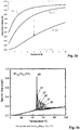
- Magnetocaloric materials e.g. Paramagnetic salts, some oxides and rare earth fluorides or so-called "Laves phase” materials - are used in magnetic coolers (for example in adiabatic demagnetization cryostats). These magnetocaloric materials are characterized in that their entropy can be changed by applying a magnetic field.
- the entropy S was normalized to the ideal gas constant R.
- the normalized entropy S / R can be reduced to a value of about 0.62 at a temperature of 5K. This is indicated in the figure by the arrow.
- This property can be used according to the invention to increase the "time-to-quench" in a cryogen-free magnet system with a superconducting main coil.
- magnetocaloric material can be placed inside a superconducting auxiliary coil.
- this accessory coil As the system cools, this accessory coil is charged, the entropy of the magnetocaloric material decreases, and heat is released. This heat is dissipated by a cryocooler. Then the additional coil is superconductingly shorted.
- the superconducting auxiliary coil When the cryocooler fails, the superconducting auxiliary coil is slowly discharged.
- the magnetocaloric material absorbs heat.
- the rate of discharge may be selected so that the rate at which heat is absorbed in the magnetocaloric material corresponds to the rate at which heat flows through the mechanical support structure or radiation, as well as the failed cryocooler, into the system, i. the main coil does not change its temperature.
- GGG has an ion density of 1.26E22 cm-3.
- the ideal gas constant R 8.314J / (mol ⁇ K) at a temperature of 5K gives an entropy of 332J / K at 1T, and an entropy of 109J / K at 6T.
- R 8.314J / (mol ⁇ K) at a temperature of 5K gives an entropy of 332J / K at 1T, and an entropy of 109J / K at 6T.
- a volume of one liter can be accommodated easily. For comparison, this corresponds to a cylinder with a length of 10cm and a diameter of about 12cm.
- One liter of liquid helium would dissipate an amount of heat of 2625J during evaporation at a temperature of 4.2K. Helium therefore has a higher volumetric efficiency, especially since the magnetocaloric heat sink must still take into account the volume of the additional coil.
- GGG Gadolinium Gallium Garnet
- DFG Gallium Lithium Fluoride
- DAG Dysprosium Aluminum Garnet
- Magnetocaloric materials also have an uncharacteristically high specific heat in certain temperature ranges. These specific heat maxima can also be used to extend the time-to-quench:
- Fig. 3b is the specific heat of the magnetocaloric material (He 0.53 Ho 0.47 ) Co 2 shown (from: Zhu Y, Asamoto K, Nishimura Y, Kouen T, Abe S, Matsumoto K, et al. Cryogenics 2011; 51: 494 ).
- the present invention can also be used to alter the specific heat of the magnetocaloric material by applying a magnetic field to the auxiliary coil to ideally match the operating temperature of the magnet. For example, if the magnet is operated at 60K and Co ( 0.53 Ho 0.47 ) Co 2 is used as the magnetocaloric material, a field of 4T - 5T could be applied with the auxiliary coil . The specific heat of the magnetocaloric material is then maximum at the operating temperature, and in the event of a radiator failure, the increase in system temperature is slowed down.
- the high heat capacity of the magnetocaloric material has another great advantage, namely that dynamic fluctuations (e.g., from the radiator) are damped.
- the additional coil described above must be mounted in the magnet system so that the magnetocaloric material can be made magnetic field-free as possible in order to maximize the possible Entropie shortung.
- This can e.g. can be achieved by suitable geometric positioning (e.g., as far away as possible from the main coil) or by forming a magnetic shield of e.g. Soft iron or a superconducting material is provided. Furthermore, it is possible to form the field of the main coil by field shaping coils so that areas with low field strength arise.
- the magnetocaloric material must be mounted in a location where the field is not too large to avoid that the material is completely saturated.
- auxiliary coil is designed as a solenoid
- a second solenoid can be placed on the outside around the field-forming unit, which is in opposite directions through current and is electrically connected in series with the auxiliary coil.
- the stray field of the additional coil is reduced.
- the magnetocaloric unit could be designed as a toroidal coil. Toroidal coils have a small stray field due to the design.
- the temperature of the magnetocaloric material In normal operation, the temperature of the magnetocaloric material must be kept constant, so that there is no change in the magnetization that could act on the field in the center of the main coil.
- this can for example be realized so that the temperature of the magnetocaloric material is constantly measured (such as with a resistance thermometer) and then by means of a PID control unit, a heater is operated, which is attached to the magnetocaloric material.
- Another possibility is to thermally isolate the magnetocaloric material so well (eg by a radiation shield) that the material is not exposed to disturbing influences such as a variable heat load from the outside, and therefore does not change its temperature. It must be ensured that the magnetocaloric unit, of course, in good Contact with the spool or with the suspension elements that it should be able to cool in the event of a PRK failure.
- the auxiliary coil can also be combined with the main coil - either so that the auxiliary coil and the main coil are connected in series, or so that there is only one coil at all, and the magnetocaloric material is arranged in the field of the main coil.
- auxiliary coil and main magnet coil are to be energized separately from each other, the wiring would look something like the one in Fig. 2a shown.
- a typical value for power dissipation in a superconducting switch in cryogenic magnet systems is 10mW.
- the field in the main coil and in the auxiliary coil could then no longer be selected independently of each other, i. in the event of failure of the active cooling system, the main coil would also be discharged simultaneously with the additional coil.
- the interconnection shown above also applies when there is no separate coil for the magnetocaloric unit, but when the magnetocaloric material is positioned in the field of the main coil.
- the heat sink is usually brought into direct thermal contact with the coil. However, since no heat is dissipated in the coil itself, it is sufficient to couple all the "heat paths" leading to the coil to the heat sink, thus trapping heat that flows along these paths.
- Another advantage is that the heat sink can be operated at a higher temperature, such as when the heat sink is optimized for 4K, but the magnet is operated at 3K. Then, the heat sink can be coupled to the coil with a thermally poorly conductive connection, and intercept incoming heat directly to the mechanical support structures, etc.
- the heat sink device is arranged in the Kryostatan Aunt relative to the superconducting magnet assembly such that the magnetocaloric material can be made magnetic field free, so that the magnetocaloric material at the end of the demagnetization process in a field ⁇ 2 Tesla located.
- the heat sink absorbs heat during demagnetization.
- the field where the demagnetization process ends is the background field generated by the main magnet at the point where the heat sink sits.
- the further the heat sink can be demagnetized the higher the entropy change in the magnetocaloric material can be, ie, the more heat can be absorbed. If the magnetocaloric material is completely field-free, the heat absorption capacity is most efficient for a given start field.
- a temperature control unit of the magnetocaloric material is present in normal operation, which in particular comprises a thermometer, a heater and an electronic thermal control unit for the heat sink device.
- the magnetization of the magnetocaloric material is temperature-dependent. As the temperature of the material, and hence its magnetization, changes, the magnetic field in the sample volume changes, and the NMR measurement would be affected. If there were no temperature stabilization, the magnetocaloric material would change temperature, e.g. the cooling capacity of the cryocooler fluctuates slightly.
- the heat sink device comprises at least one - if necessary additional - magnetic coil.
- the magnetic field at the location of the heat sink must be changed. This is easiest to realize when the heat sink is equipped with its own coil.
- the same power supply for the main field magnet and the coil can be used in the heat sink, which reduces the complexity of the system, and also the heat load during operation. How out Fig. 2a can be seen, then two superconducting switches are necessary for this.
- the magnetic coil of the heat sink device is electrically connected in series with a coil of the superconducting magnet assembly.
- cryostat assembly in which the heat sink device, in particular a magnetic coil in the heat sink device, is surrounded by a magnetic shield.
- the minimum field to which demagnetization can be achieved is smaller than without shielding, which means increased efficiency.
- disturbances in the sample volume caused by the heat sink e.g. because the temperature of the magnetocaloric material changes, or because the current in the coil of the heat sink is changed - attenuated at the site of the sample volume.
- a first advantageous development of this class of embodiments is characterized in that the magnetic shield of the heat sink device comprises an active shielding magnet coil.
- the magnetic shield of the heat sink device a passive magnetic shield assembly, in particular of superconducting material, soft iron or from a short-circuited superconducting wire coil include.
- Such a solution is particularly inexpensive, technically easy to implement, and is very well suited to suppress field disturbances due to temperature changes of the magnetocaloric material.
- Embodiments of the inventive cryostat arrangement are also preferred, characterized in that the superconducting magnet arrangement comprises HTS elements.
- HTS material lies in the fact that either very high fields can be achieved, or the magnet can be operated at comparatively high temperatures, which simplifies the cooling system.
- Embodiments of the inventive cryostat arrangement in which the cryostat arrangement is part of a magnetic resonance apparatus are also very particularly preferred.
- FIG. 1 illustrates very schematically a possible embodiment of the cryostat arrangement according to the invention. This can be kept dry by means of a cryocooler 4 , ie without the provision or supply of cryogenic fluids, at a cryogenic operating temperature.
- a cryocooler 4 ie without the provision or supply of cryogenic fluids, at a cryogenic operating temperature.
- the cryostat arrangement is characterized in that the heat sink device contains magnetocaloric material 3 , and that the heat sink device is thermally conductive with the superconducting Magnetic arrangement 1 and / or is connected to parts of the Kryostatan Aunt, via which ambient heat can flow to the magnet assembly 1.
- the heat sink device comprises an additional magnetic coil.
- the solenoid coil 2 of the heat sink device may be superconductingly short-circuited in the operating state and preferably electrically connected to a coil of the superconducting magnet assembly 1, as in FIGS FIGS. 2a and 2b is shown.
- Fig. 2b a variant of the invention is shown in which the magnetic coil 2 of the heat sink device electrically connected in series with a coil of the superconducting magnet assembly 1 and arranged spatially so that they together form a magnetic field generating coil.
- Those parts of the cryostat arrangement according to the invention via which ambient heat can flow to the magnet arrangement 1, comprise parts of the cryocooler 4 and / or radiation shields and / or mechanical suspension devices 5 for the magnet arrangement 1 and / or electrical supply lines to the magnet arrangement 1 arranged within the cryostat arrangement.
- the heat sink device in the Kryostatan Aunt is arranged relative to the superconducting magnet assembly 1 such that the magnetocaloric material 3 can be made as free of magnetic field in operation, so that the magnetocaloric material is at the end of the demagnetization process in a field ⁇ 2 Tesla.
- the main field of application of the cryostat arrangement according to the invention is the use in magnetic resonance apparatuses.
Landscapes
- Engineering & Computer Science (AREA)
- Physics & Mathematics (AREA)
- Mechanical Engineering (AREA)
- Thermal Sciences (AREA)
- General Engineering & Computer Science (AREA)
- Condensed Matter Physics & Semiconductors (AREA)
- General Physics & Mathematics (AREA)
- Electromagnetism (AREA)
- Chemical & Material Sciences (AREA)
- Combustion & Propulsion (AREA)
- Power Engineering (AREA)
- Magnetic Resonance Imaging Apparatus (AREA)
- Containers, Films, And Cooling For Superconductive Devices (AREA)
Abstract
Description
- Die Erfindung betrifft eine Kryostatanordnung, die mittels eines Kryokühlers trocken, also ohne Bereitstellung oder Zufuhr von kryogenen Fluiden, auf einer kryogenen Betriebstemperatur gehalten werden kann, wobei in der Kryostatanordnung zumindest im Betrieb eine supraleitende Magnetanordnung sowie eine Wärmesenke-Einrichtung zur Verlängerung der Zeit bis zur Rückkehr der supraleitenden Magnetanordnung in den normalleitenden Zustand (="Time-to-Quench") bei Versagen der aktiven Kühlung vorhanden sind.
- Eine solche Kryostatanordnung, die allerdings immer noch geringe Mengen an flüssigem Kryogen enthält, ist an sich bekannt, etwa aus
EP 0 937 953 A1 oder ausDE199 14 778 B4 . - Das Einsatzgebiet der vorliegenden Erfindung bildet ein kryogenes System zur Kühlung eines supraleitenden Magnetspulensystems, wie es beispielsweise für Anwendungen der Magnetresonanzspektroskopie (=NMR) oder der Magnetresonanztomographie (=MRI) eingesetzt wird. Die Anwendbarkeit der Erfindung ist jedoch nicht auf dieses Gebiet beschränkt.
- Supraleitende Magnete müssen auf kryogene Temperaturen gekühlt werden, um funktionsfähig zu sein. Viele Anwender bevorzugen dabei "kryogenfreie" Magnete, die zur Gänze auf den Einsatz von Kryogenen (z.B. flüssiges Helium und/oder flüssigen Stickstoff) verzichten, und die Betriebstemperatur ausschließlich mit sogenannten "Kryokühlern", also "trocken" aufrechterhalten. Typischerweise kommen hier Pulsrohr-, Stirling- oder Gifford-McMahonkühler zum Einsatz.
- Der Nachteil eines solchen kryogenfreien Magnetsystems besteht in der teilweise sehr kurzen "Time-to-Quench". Bei einem Ausfall des Kryokühlers (üblicherweise bedingt durch einen Stromausfall, eine Unterbrechung in der Kühlwasserversorgung, oder einen mechanischen Defekt am Kompressor oder Kaltkopf) wärmt sich das Magnetsystem sehr schnell über die zulässige Betriebstemperatur auf und quencht. Das Magnetsystem ist dann für längere Zeit nicht mehr benutzbar, da es wieder abgekühlt und neu geladen werden muss.
- Eine Möglichkeit, die "Time-to-Quench" zu verlängern, besteht darin, geringe Mengen eines Kryogens vorzusehen, dessen Verdampfungswärme die Temperatur des Magnets im Falle eines Kühlerausfalls konstant hält. Diese Technik wird üblicherweise als "Minimum Condensed Volume" bezeichnet. Nachteilig ist, dass auch der Einsatz geringer Mengen eines Kryogens strenggenommen nicht mehr kompatibel mit der Definition "cryogen-free" ist.
- Außerdem muss ein System vorgesehen werden, um das Kryogen beim Abkühlen des Magnets kondensieren zu können. Ebenfalls nachteilig ist, dass -bedingt durch die begrenzte Anzahl praktisch einsetzbarer Kryogene- nur einige wenige Betriebstemperaturfenster möglich sind (z.B. ca. 2,5K - 4,5K für He, ca. 70K - 77K für LN2, etc).
- Nach der eingangs zitierten
EP 0 937 953 A1 wird die "Time-to-Quench" verlängert, indem kleine Mengen eines Kryogens in einem dafür vorgesehenen Reservoir bevorratet werden. Die Spule selbst liegt innerhalb dieses Reservoirs. Gegenüber einem "gewöhnlichen" Heliumtank ist dieses Reservoir zwar deutlich kleiner ausgebildet, um die Kryogenmenge so klein wie möglich zu halten. Wirklich "trocken" im strengen Sinne ist diese Anordnung allerdings dennoch nicht. - Auch bei der Kryostatanordnung nach der-ebenfalls eingangs zitierten-
DE 199 14 778 B4 wird die "Time-to-Quench" dadurch verlängert, dass kleine Mengen eines Kryogens in einem dafür vorgesehenen Reservoir bevorratet werden. Die Spule selbst liegt allerdings im Vakuum, und ist thermisch mit dem Reservoir verbunden. -
DE 10 2014 218 773 A1 : Auch diese Erfindung hat die Verlängerung der "Time-to-Quench" zum Ziel. Es wird dort allerdings ein gänzlich anderer Ansatz verfolgt: Anstatt die Wärmekapazität bzw. die zu Verfügung stehende Wärmekapazität zu erhöhen, wird bei einem Ausfall des aktiven Kühlers die thermische Kopplung zwischen Spule und Kühler reduziert. - Der vorliegenden Erfindung liegt demgegenüber die Aufgabe zugrunde, eine "trockene" Kryostatanordnung der eingangs beschriebenen Art mit einem supraleitenden Magnetspulensystem mit möglichst einfachen technischen Mitteln dahingehend zu verbessern, dass die oben diskutierten Nachteile bekannter gattungsgemäßer Anordnungen vermieden werden. Insbesondere soll die Kryostatanordnung wirklich "kryogenfrei" betreibbar sein und bei eventuellen Betriebsstörungen eine ausreichend lange "Time-to-Quench" ermöglichen.
- Diese Aufgabe wird erfindungsgemäß auf ebenso überraschend einfache wie wirkungsvolle Weise sowie mit ohne Weiteres zur Verfügung stehenden technischen Mitteln dadurch gelöst, dass die Wärmesenke-Einrichtung magnetokalorisches Material enthält, und dass die Wärmesenke-Einrichtung thermisch leitend mit der supraleitenden Magnetanordnung und/oder mit Teilen der Kryostatanordnung verbunden ist, über welche Umgebungswärme auf die Magnetanordnung fließen kann.
- Die vorliegende Erfindung schlägt also eine Kryostatanordnung vor, welche es ermöglicht, eine supraleitende Magnetanordnung wirklich "trocken" zu betreiben, also ohne Zufuhr von kryogenen Fluiden auf einer kryogenen Betriebstemperatur zu halten, und diese Betriebstemperatur auch im Falle des Versagen der aktiven Kühlung für eine signifikante Zeitdauer aufrechtzuerhalten (Verlängerung der "Time-to-Quench").
- Zur effektiven Verlängerung der "Time-to-Quench" macht sich die Erfindung den magnetokalorischen Effekt zunutze, durch den magnetokalorisches Material seiner Umgebung bei annähernd konstanter Temperatur Wärme entzieht, wenn es entmagnetisiert wird. Auch Varianten, bei welchen das Material nicht entmagnetisiert wird, sondern nur ein Magnetfeld angelegt wird, um die spezifische Wärme zu maximieren, sind von der vorliegenden Erfindung umfasst.
- Der sogenannte magnetokalorische Effekt beschreibt die thermische Reaktion eines Systems auf eine Änderung des Magnetfelds. Magnetokalorische Materialen - z.B. paramagnetische Salze, einige Oxide und Fluoride seltener Erden oder sogenannte "Laves-Phasen" Materialen - werden unter anderem in magnetischen Kühlern (zum Beispiel in adiabatischen Entmagnetisierungs-Kryostaten) eingesetzt. Diese magnetokalorischen Materialien zeichnen sich dadurch aus, dass deren Entropie durch Anlegen eines Magnetfelds verändert werden kann.
- Beispielhaft ist in
Fig. 3a ein Entropie-Temperaturdiagramm für das magnetokalorische Material GGG (Gadolinium Gallium Garnet) für drei verschiedene Magnetfelder (B = 1 T, 2T und 6T) gezeigt. Die Entropie S wurde auf die ideale Gaskonstante R normiert. - Durch Anlegen eines Magnetfelds von 6T kann bei einer Temperatur von 5K die normierte Entropie S/R also auf einen Wert von etwa 0,62 gesenkt werden. Dies ist in der Abbildung durch den Pfeil angedeutet.
- Findet in einem isothermen Prozess bei der Temperatur T eine Entropieveränderung ΔS statt, wird eine Wärmemenge Q entweder frei oder adsorbiert:

- Wenn die Entropie gesenkt wird (d.h. bei der Magnetisierung des magnetokalorischen Materials), wird Wärme frei, bei der Demagnetisierung wird Wärme adsorbiert.
- Diese Eigenschaft kann man sich erfindungsgemäß zu Nutze machen, um in einem kryogenfreien Magnetsystem mit einer supraleitenden Hauptspule die "Time-to-Quench" zu erhöhen. Dafür kann magnetokalorisches Material beispielsweise innerhalb einer supraleitenden Zusatzspule platziert werden.
- Beim Abkühlen des Systems wird diese Zusatzspule geladen, die Entropie des magnetokalorischen Materials nimmt ab, und Wärme wird frei. Diese Wärme wird von einem Kryokühler abgeführt. Dann wird die Zusatzspule supraleitend kurzgeschlossen.
- Wenn der Kryokühler ausfällt, wird die supraleitende Zusatzspule langsam entladen. Dabei absorbiert das magnetokalorische Material Wärme. Die Entladegeschwindigkeit kann so gewählt werden, dass die Rate, mit der Wärme im magnetokalorischen Material absorbiert wird, der Rate entspricht, mit der Wärme über die mechanische Trägerstruktur bzw. Stromzuleitungen oder Strahlung, sowie den ausgefallenen Kryokühler ins System fließt, d.h. die Hauptspule verändert ihre Temperatur nicht.
- GGG hat eine Ionendichte von 1,26E22 cm-3. Für ein Volumen von einem Liter ergeben sich mit der idealen Gaskonstante R = 8,314J/(mol·K) bei einer Temperatur von 5K eine Entropie von 332J/K bei 1T, und eine Entropie von 109J/K bei 6T. Bei einer Temperatur von 5K können bei einer Entmagnetisierung von 6T auf 1 T also 1115J absorbiert werden. Bei einer Wärmelast von 100mW = 0,1W verlängert das die "Time-to-Quench" um 11150 Sekunden oder um etwas mehr als drei Stunden.
- Ein Volumen von einem Liter kann leicht untergebracht werden. Zum Vergleich: Das entspricht einem Zylinder mit einer Länge von 10cm und einem Durchmesser von etwa 12cm. Ein Liter flüssiges Helium würde bei der Verdampfung bei einer Temperatur von 4,2K etwa eine Wärmemenge von 2625J abführen. Helium hat also eine höhere volumetrische Effizienz, besonders, da bei der magnetokalorischen Wärmesenke noch das Volumen der Zusatzspule berücksichtigt werden muss.
- Da viele Vorrichtungen, die für den Betrieb einer supraleitenden Magnetspule benötigt werden, in einem kryogenfreien Magneten in der Regel schon vorhanden sind (Isolationsvakuum, Stromzuführungen, etc), ist der Einbau einer solchen zusätzlichen Spule verhältnismäßig einfach zu realisieren.
- Mögliche magnetokalorische Materialien sind: GGG (Gadolinium Gallium Garnet), Dysprosium Gallium Garnet (DGG), Gallium Lithium Fluorid (GLF), Dysprosium Aluminium Garnet (DAG), etc. Welches Material verwendet werden sollte, hängt stark von der Temperatur ab, bei der der Magnet betrieben wird.
- Magnetokalorische Materialien weisen in gewissen Temperaturbereichen auch eine uncharakteristisch hohe spezifische Wärme auf. Diese Maxima der spezifischen Wärme können ebenfalls genutzt werden, um die "Time-to-Quench" zu verlängern:
- In
Fig. 3b ist die spezifische Wärme des magnetokalorischen Materials (Er0.53Ho0.47)Co2 gezeigt (aus: Zhu Y, Asamoto K, Nishimura Y, Kouen T, Abe S, Matsumoto K, et al. Cryogenics 2011;51:494). - Die vorliegende Erfindung kann auch dazu genutzt werden, die spezifische Wärme des magnetokalorischen Materials durch Anlegen eines Magnetfelds mit der Zusatzspule so zu verändern, dass sie ideal zur Betriebstemperatur des Magneten passt. Wird der Magnet z.B. bei 60K betrieben und würde (Er0.53Ho0.47)Co2 als magnetokalorisches Material verwendet, könnte mit der Zusatzspule ein Feld von 4T - 5T angelegt werden. Die spezifische Wärme des magnetokalorischen Materials ist dann bei der Betriebstemperatur maximal, und im Falle eines Kühlerausfalls wird der Anstieg der Systemtemperatur verlangsamt.
- Die hohe Wärmekapazität des magnetokalorischen Materials hat einen weiteren großen Vorteil, nämlich dass dynamische Fluktuationen (z.B. vom Kühler) abgedämpft werden.
- Die oben beschrieben Zusatzspule muss so im Magnetsystem angebracht werden, dass das magnetokalorische Material möglichst magnetfeldfrei gemacht werden kann, um die mögliche Entropieänderung zu maximieren.
- Das kann z.B. durch geeignete geometrische Positionierung erreicht werden (z.B. möglichst weit weg von der Hauptspule), oder indem ein magnetischer Schild aus z.B. Weicheisen oder einem supraleitenden Material vorgesehen wird. Des Weiteren ist es möglich, das Feld der Hauptspule durch Feldformspulen so zu formen, dass Bereiche mit niedriger Feldstärke entstehen.
- Außerdem muss das magnetokalorische Material an einer Stelle angebracht sein, an der das Feld nicht zu groß ist, um zu vermeiden, dass das Material komplett gesättigt ist.
- Im Wesentlichen gibt es hier die gleichen Lösungsmöglichkeiten wie bereits oben geschildert: Die Geometrie sollte entsprechend gewählt werden (z.B. weit weg), Einsatz magnetischer bzw. supraleitender Schilde, und Feldformspulen. Der Fachmann kennt diese Möglichkeiten. Es gibt auch recht nahe am Magneten Bereiche mit sehr niedriger Feldstärke. Zum Teil liegen die Feldnullstellen aufgrund der Abschirmung innerhalb der Hauptspule.
- Durch geeignete Anordnung und/oder Abschirmung sollte die Feldveränderung, die sich durch Betätigen der Zusatzspule im Zentrum der Hauptspule ergibt, gering gehalten werden.
- Auch hier sind die oben genannten Lösungen hilfreich. Es besteht nun allerdings auch die Möglichkeit, die magnetokalorische Einheit selbst aktiv abzuschirmen. Wenn die Zusatzspule als Solenoid ausgeführt ist, kann ein zweiter Solenoid außen um die Feldformeinheit gelegt werden, der gegenläufig stromdurchflossen ist und elektrisch in Serie mit der Zusatzspule geschaltet ist. Dadurch wird das Streufeld der Zusatzspule verkleinert. Dem Fachmann ist bekannt, wie das geht. Alternativ könnte die magnetokalorische Einheit als Ringkernspule ausgeführt werden. Ringkernspulen haben bauartbedingt ein geringes Streufeld.
- Im Normalbetrieb muss die Temperatur des magnetokalorischen Materials konstant gehalten werden, damit sich keine Veränderung der Magnetisierung ergibt, die auf das Feld im Zentrum der Hauptspule wirken könnte. Technisch kann das z.B. so realisiert werden, dass die Temperatur des magnetokalorischen Materials ständig gemessen wird (etwa mit einem Widerstandsthermometer) und dann mittels einer PID Regeleinheit ein Heizer betrieben wird, der am magnetokalorischen Material angebracht ist. Eine andere Möglichkeit besteht darin, das magnetokalorische Material thermisch so gut zu isolieren (z.B. durch einen Strahlungsschild), dass das Material keinen Störeinflüssen wie beispielsweise einer variablen Wärmelast von außen ausgesetzt ist, und deshalb seine Temperatur nicht ändert. Dabei muss darauf geachtet werden, dass die magnetokalorische Einheit natürlich in gutem Kontakt mit der Spule oder mit den Aufhängeelementen, die sie im Falle eines PRK Ausfalls kühlen soll, sein muss.
- Die Zusatzspule kann auch mit der Hauptspule kombiniert werden - entweder so, dass die Zusatzspule und die Hauptspule in Serie miteinander verschaltet sind, oder so, dass es überhaupt nur eine Spule gibt, und das magnetokalorische Material im Feld der Hauptspule angeordnet ist.
- Wenn Zusatzspule und Hauptmagnetspule getrennt voneinander bestromt werden sollen, würde die Verschaltung etwa so aussehen, wie in
Fig. 2a dargestellt. - Dabei ist besonders darauf zu achten, dass die Leistungsdissipation in den supraleitenden Schaltern bei deren Öffnung klein bleibt. Ein typischer Wert für die Leistungsdissipation in einem supraleitenden Schalter in kryogenfreien Magnetsystemen ist 10mW.
- Um den Aufbau zu vereinfachen, könnte auf einen der beiden Schalter verzichtet werden, wie in
Fig. 2b dargestellt: - Das Feld in der Hauptspule und in der Zusatzspule könnten dann nicht mehr unabhängig voneinander gewählt werden, d.h. bei einem Ausfall der aktiven Kühlung würde gleichzeitig mit der Zusatzspule auch gleich die Hauptspule entladen. Die oben gezeigte Verschaltung trifft auch zu, wenn es gar keine separate Spule für die magnetokalorische Einheit gibt, sondern wenn das magnetokalorische Material im Feld der Hauptspule positioniert wird.
- Besonders bevorzugt sind Ausführungsformen der Erfindung, bei denen die Wärmesenke-Einrichtung thermisch leitend mit Teilen der Kryostatanordnung verbunden ist, über welche Umgebungswärme auf die Magnetanordnung fließen kann, und diese Teile innerhalb der Kryostatanordnung angeordnete Teile des Kryokühlers und/oder Strahlungsschilde und/oder mechanische Aufhängevorrichtungen für die Magnetanordnung und/oder elektrische Zuleitungen zur Magnetanordnung umfassen.
- Die Wärmesenke wird üblicherweise direkt mit der Spule in thermischen Kontakt gebracht. Da in der Spule selbst aber keine Wärme dissipiert wird, reicht es aus, alle "Wärmepfade", die zur Spule führen, an die Wärmesenke anzukoppeln, und so Wärme, die entlang dieser Pfade fließt, abzufangen. Ein weiterer Vorteil besteht darin, dass die Wärmesenke bei höherer Temperatur betrieben werden kann, etwa wenn die Wärmesenke für 4K optimiert ist, der Magnet aber bei 3K betrieben wird. Dann kann die Wärmesenke mit einer thermisch schlecht leitenden Verbindung an die Spule angekoppelt werden, und einfließende Wärme direkt an den mechanischen Trägerstrukturen, etc. abfangen.
- Vorteilhafte Weiterbildungen dieser Ausführungsformen sind dadurch gekennzeichnet, dass die Wärmesenke-Einrichtung in der Kryostatanordnung relativ zur supraleitenden Magnetanordnung derart angeordnet ist, dass das magnetokalorische Material möglichst magnetfeldfrei gemacht werden kann , so dass sich das magnetokalorische Material am Ende des Entmagnetisierungsprozesses in einem Feld < 2 Tesla befindet.
- Die Wärmesenke absorbiert bei der Entmagnetisierung Wärme. Das Feld, bei dem der Entmagnetisierungsprozess endet, ist das Hintergrundfeld, das vom Hauptmagnet an der Stelle, an der die Wärmesenke sitzt, erzeugt wird. Je weiter die Wärmesenke entmagnetisiert werden kann, desto höher kann die Entropieänderung im magnetokalorischen Material sein, d.h. desto mehr Wärme kann absorbiert werden. Wenn das magnetokalorische Material komplett feldfrei ist, ist die Wärmeaufnahmekapazität bei gegebenem Startfeld am effizientesten.
- In der Praxis bewähren sich auch Ausführungsformen der Erfindung, bei welchen eine Temperaturregeleinheit des magnetokalorischen Materials im Normalbetrieb vorhanden ist, die insbesondere ein Thermometer, eine Heizeinrichtung und eine elektronische Wärmeregeleinheit für die Wärmesenke-Einrichtung umfasst.
- Die Magnetisierung des magnetokalorischen Materials ist temperaturabhängig. Wenn sich die Temperatur des Materials, und damit dessen Magnetisierung ändert, verändert sich das Magnetfeld im Probenvolumen, und die NMR Messung würde beeinflusst. Wenn es keine Temperaturstabilisierung gäbe, würde das magnetokalorische Material seine Temperatur ändern, wenn z.B. die Kühlleistung des Kryokühlers leicht schwankt.
- Ganz besonders bevorzugt ist eine Klasse von Ausführungsformen der erfindungsgemäßen Kryostatanordnung, bei denen die Wärmesenke-Einrichtung mindestens eine -gegebenenfalls zusätzliche- Magnetspule umfasst.
- Für die Entmagnetisierung des magnetokalorischen Materials muss das Magnetfeld am Ort der Wärmesenke verändert werden. Dies ist am einfachsten zu realisieren, wenn die Wärmesenke mit einer eigenen Spule ausgerüstet ist.
- Wenn eine eigene Spule verwendet wird, ergibt sich auch die Möglichkeit, das Feld der Spule in der Wärmesenke unabhängig vom Feld des Hauptfeldmagneten zu verändern. Das ist von Vorteil, da im Falle eines Kühlerausfalls erst nur die Spule der Wärmesenke entladen werden kann, bevor der Hauptfeldmagnet "angefasst" werden muss.
- Vorteilhafte Weiterbildungen dieser Klasse von Ausführungsformen sind dadurch gekennzeichnet, dass die Magnetspule der Wärmesenke-Einrichtung im Betriebszustand supraleitend kurzgeschlossen ist.
- Dann muss kein Strom von einem externen Netzgerät in die Magnetspule eingespeist werden, was die Wärmelast auf das Gesamtsystem verringert (kein ohmsches Heizen in den Zuleitungen zur Magnetspule).
- Andere vorteilhafte Weiterbildungen zeichnen sich dadurch aus, dass die Magnetspule der Wärmesenke-Einrichtung mit einer Spule der supraleitenden Magnetanordnung elektrisch verbunden ist.
- Damit kann die gleiche Stromzuführung für den Hauptfeldmagnet und die Spule in der Wärmesenke verwendet werden, wodurch sich die Komplexität des Systems verringert, und auch die Wärmelast im Betrieb. Wie aus
Fig. 2a zu sehen ist, sind dafür dann zwei supraleitende Schalter nötig. - Bei einer bevorzugten Klasse von Varianten ist die Magnetspule der Wärmesenke-Einrichtung mit einer Spule der supraleitenden Magnetanordnung elektrisch in Serie geschaltet.
- Hier liegt der größte Vorteil in einer Verringerung der Systemkomplexität. Wie aus
Fig. 2b zu sehen ist, kann auf diese Weise ein Schalter eingespart werden. Nachteilig ist, dass natürlich auch die Betriebsweise eingeschränkt ist, da die Wärmesenke nicht mehr unabhängig vom Hauptmagnet gesteuert werden kann. - Besonders kompakt sind Weiterbildungen, bei welchen die Magnetspule der Wärmesenke-Einrichtung und die Spule der supraleitenden Magnetanordnung räumlich so angeordnet und elektrisch derart miteinander verschaltet sind, dass sie gemeinsam eine magnetfelderzeugende Spule bilden.
- Das ist die einfachste Anordnung, die die Komplexität so weit wie möglich verringert. Wenn der Kühler ausfällt, wird gleich der Hauptfeldmagnet entladen, und dadurch wird das magnetokalorische Material entmagnetisiert.
- Vorteilhaft ist auch eine Klasse von Ausführungsformen der erfindungsgemäßen Kryostatanordnung, bei denen die Wärmesenke-Einrichtung, insbesondere eine Magnetspule in der Wärmesenke-Einrichtung, von einer magnetischen Abschirmung umgeben ist.
- Das bringt gleich mehrere Vorteile: Zum einen ist das Minimalfeld, bis zu dem entmagnetisiert werden kann, kleiner als ohne Abschirmung, was eine erhöhte Effizienz bedeutet. Außerdem werden von der Wärmesenke verursachte Störungen im Probenvolumen -z.B. weil sich die Temperatur des magnetokalorischen Materials verändert, oder weil der Strom in der Spule der Wärmesenke verändert wird- am Ort des Probenvolumens abgeschwächt.
- Eine erste vorteilhafte Weiterbildung dieser Klasse von Ausführungsformen ist dadurch gekennzeichnet, dass die magnetische Abschirmung der Wärmesenke-Einrichtung eine aktive Abschirm-Magnetspule umfasst.
- Hier gelten die gleichen Vorteile wie oben diskutiert, hauptsächlich aber, dass Änderungen im Strom der Spule in der Wärmesenke nur eine kleine Veränderung des Magnetfelds außerhalb der Wärmesenke hervorrufen. Außerdem sind aktive Abschirmspulen besonders kompakt und effizient.
- Alternativ kann aber bei einer anderen Weiterbildung die magnetische Abschirmung der Wärmesenke-Einrichtung eine passive Magnetschildanordnung, insbesondere aus supraleitendem Material, aus Weicheisen oder aus einer in sich kurzgeschlossenen Spule aus supraleitendem Draht, umfassen.
- Eine solche Lösung ist besonders preiswert, technisch einfach zu realisieren, und ist sehr gut geeignet, Feldstörungen durch Temperaturänderungen des magnetokalorischen Materials zu unterdrücken.
- Bevorzugt sind auch Ausführungsformen der erfindungsgemäßen Kryostatanordnung, sich dadurch auszeichnen, dass die supraleitende Magnetanordnung HTS-Elemente umfasst.
- Der Vorteil beim Einsatz von HTS-Material liegt vor allem darin, dass sich entweder besonders hohe Felder erreichen lassen, oder der Magnet bei vergleichsweise hohen Temperaturen betrieben werden kann, was das Kühlsystem vereinfacht.
- Ganz besonders bevorzugt sind auch Ausführungsformen der erfindungsgemäßen Kryostatanordnung, bei welchen die Kryostatanordnung Teil einer Magnetresonanz-Apparatur ist.
- Schließlich ist es auch von erheblichem Vorteil, wenn die erfindungsgemäße Kryostatanordnung das magnetokalorische Material der Wärmesenke-Einrichtung GGG (=Gadolinium Gallium Garnet), DGG (=Dysprosium Gallium Garnet), GLF (=Gallium Lithium Fluorid") oder DAG (=Dysprosium Aluminium Garnet) enthält.
- Die Erfindung ist in der Zeichnung dargestellt und wird anhand von Ausführungsbeispielen näher erläutert. Es zeigen:
- Fig. 1
- eine schematische vertikale Schnitt-Darstellung einer Ausführungsform der erfindungsgemäßen Kryostatanordnung;
- Fig. 2a
- ein elektrisches Schaltschema einer erfindungsgemäßen magnetokalorischen Zusatzspule parallel zur Hauptfeldspule der supraleitenden Magnetanordnung;
- Fig. 2b
- ein Schaltschema wie in
Fig. 2a , jedoch mit elektrisch in Serie geschalteten Spulen; - Fig. 3a
- ein Entropie-Temperaturdiagramm für das magnetokalorische Material GGG (Gadolinium Gallium Garnet) für drei verschiedene Magnetfelder (B = 1T, 2T und 6T), wobei die Entropie S auf die ideale Gaskonstante R normiert ist; und
- Fig. 3b
- die spezifische Wärme von magnetokalorischen Materials (Er0.53Ho0.47)Co2 als Funktion der Temperatur.
- Die
Figur 1 veranschaulicht sehr schematisch eine mögliche Ausführungsform der erfindungsgemäßen Kryostatanordnung. Diese kann mittels eines Kryokühlers 4 trocken, also ohne Bereitstellung oder Zufuhr von kryogenen Fluiden, auf einer kryogenen Betriebstemperatur gehalten werden,. In der Kryostatanordnung sind zumindest im Betrieb eine supraleitende Magnetanordnung 1 sowie eine Wärmesenke-Einrichtung zur Verlängerung der Zeit bis zur Rückkehr der supraleitenden Magnetanordnung 1 in den normalleitenden Zustand (="Time-to-Quench") bei Versagen der aktiven Kühlung vorhanden. - Erfindungsgemäß zeichnet sich die Kryostatanordnung dadurch aus, dass die Wärmesenke-Einrichtung magnetokalorisches Material 3 enthält, und dass die Wärmesenke-Einrichtung thermisch leitend mit der supraleitenden Magnetanordnung 1 und/oder mit Teilen der Kryostatanordnung verbunden ist, über welche Umgebungswärme auf die Magnetanordnung 1 fließen kann.
- Im dargestellten Ausführungsbeispiel umfasst die Wärmesenke-Einrichtung eine zusätzliche Magnetspule 2.
Die Magnetspule 2 der Wärmesenke-Einrichtung kann im Betriebszustand supraleitend kurzgeschlossen und vorzugsweise mit einer Spule der supraleitenden Magnetanordnung 1 elektrisch verbunden sein, wie in denFiguren 2a und 2b gezeigt ist. - In
Fig. 2b ist eine Variante der Erfindung dargestellt, bei welcher die Magnetspule 2 der Wärmesenke-Einrichtung mit einer Spule der supraleitenden Magnetanordnung 1 elektrisch in Serie geschaltet und räumlich so angeordnet, dass sie gemeinsam eine magnetfelderzeugende Spule bilden. - Diejenigen Teile der erfindungsgemäßen Kryostatanordnung, über welche Umgebungswärme auf die Magnetanordnung 1 fließen kann, umfassen innerhalb der Kryostatanordnung angeordnete Teile des Kryokühlers 4 und/oder Strahlungsschilde und/oder mechanische Aufhängevorrichtungen 5 für die Magnetanordnung 1 und/oder elektrische Zuleitungen zur Magnetanordnung1.
- Die Wärmesenke-Einrichtung in der Kryostatanordnung ist relativ zur supraleitenden Magnetanordnung 1 derart angeordnet, dass das magnetokalorische Material 3 auch im Betrieb möglichst magnetfeldfrei gemacht werden kann, so dass sich das magnetokalorische Material am Ende des Entmagnetisierungsprozesses in einem Feld < 2 Tesla befindet.
- Haupt-Anwendungsgebiet der erfindungsgemäßen Kryostatanordnung ist der Einsatz in Magnetresonanzapparaturen.
-
- 1
- supraleitende Magnetanordnung
- 2
- zusätzliche Magnetspule
- 3
- magnetokalorisches Material
- 4
- Kryokühler
- 5
- mechanische Aufhängevorrichtungen
Claims (15)
- Kryostatanordnung, die mittels eines Kryokühlers (4) trocken, also ohne Bereitstellung oder Zufuhr von kryogenen Fluiden, auf einer kryogenen Betriebstemperatur gehalten werden kann, wobei in der Kryostatanordnung zumindest im Betrieb eine supraleitende Magnetanordnung (1) sowie eine Wärmesenke-Einrichtung zur Verlängerung der Zeit bis zur Rückkehr der supraleitenden Magnetanordnung (1) in den normalleitenden Zustand (="Time-to-Quench") bei Versagen der aktiven Kühlung vorhanden sind,
dadurch gekennzeichnet,
dass die Wärmesenke-Einrichtung magnetokalorisches Material (3) enthält,
und dass die Wärmesenke-Einrichtung thermisch leitend mit der supraleitenden Magnetanordnung (1) und/oder mit Teilen der Kryostatanordnung verbunden ist, über welche Umgebungswärme auf die Magnetanordnung (1) fließen kann. - Kryostatanordnung nach Anspruch 1, dadurch gekennzeichnet, dass die Teile der Kryostatanordnung, über welche Umgebungswärme auf die Magnetanordnung (1) fließen kann, innerhalb der Kryostatanordnung angeordnete Teile des Kryokühlers (4) und/oder Strahlungsschilde und/oder mechanische Aufhängevorrichtungen (5) für die Magnetanordnung (1) und/oder elektrische Zuleitungen zur Magnetanordnung (1) umfassen.
- Kryostatanordnung nach Anspruch 1 oder 2, dadurch gekennzeichnet,
dass die Wärmesenke-Einrichtung in der Kryostatanordnung relativ zur supraleitenden Magnetanordnung (1) derart angeordnet ist, dass das magnetokalorische Material (3) möglichst magnetfeldfrei gemacht werden kann, so dass sich das magnetokalorische Material am Ende des Entmagnetisierungsprozesses in einem Feld von < 2 Tesla befindet. - Kryostatanordnung nach einem der vorhergehenden Ansprüche, dadurch gekennzeichnet, dass eine Vorrichtung zur Konstanthaltung der Temperatur des magnetokalorischen Materials (3) im Normalbetrieb vorhanden ist, die insbesondere ein Thermometer, eine Heizeinrichtung und eine elektronische Wärmeregeleinheit für die Wärmesenke-Einrichtung umfasst.
- Kryostatanordnung nach einem der vorhergehenden Ansprüche, dadurch gekennzeichnet, dass die Wärmesenke-Einrichtung mindestens eine -gegebenenfalls zusätzliche- Magnetspule (2) umfasst.
- Kryostatanordnung nach Anspruch 5, dadurch gekennzeichnet, dass die Magnetspule (2) der Wärmesenke-Einrichtung im Betriebszustand supraleitend kurzgeschlossen ist
- Kryostatanordnung nach Anspruch 5 oder 6, dadurch gekennzeichnet, dass die Magnetspule (2) der Wärmesenke-Einrichtung mit einer Spule der supraleitenden Magnetanordnung (1) elektrisch verbunden ist.
- Kryostatanordnung nach Anspruch 7, dadurch gekennzeichnet, dass die Magnetspule (2) der Wärmesenke-Einrichtung mit einer Spule der supraleitenden Magnetanordnung (1) elektrisch in Serie geschaltet ist.
- Kryostatanordnung nach Anspruch 8, dadurch gekennzeichnet, dass die Magnetspule (2) der Wärmesenke-Einrichtung und die Spule der supraleitenden Magnetanordnung (1) räumlich so angeordnet und elektrisch derart miteinander verschaltet sind, dass sie gemeinsam eine magnetfelderzeugende Spule bilden.
- Kryostatanordnung nach einem der vorhergehenden Ansprüche, dadurch gekennzeichnet, dass die Wärmesenke-Einrichtung, insbesondere eine Magnetspule (2) in der Wärmesenke-Einrichtung, von einer magnetischen Abschirmung umgeben ist.
- Kryostatanordnung nach Anspruch 10, dadurch gekennzeichnet, dass die. magnetische Abschirmung der Wärmesenke-Einrichtung eine aktive Abschirm-Magnetspule umfasst.
- Kryostatanordnung nach Anspruch 10, dadurch gekennzeichnet, dass die. magnetische Abschirmung der Wärmesenke-Einrichtung eine passive Magnetschildanordnung, insbesondere aus supraleitendem Material, aus Weicheisen oder aus einer in sich kurzgeschlossenen Spule aus supraleitendem Draht, umfasst.
- Kryostatanordnung nach einem der vorhergehenden Ansprüche, dadurch gekennzeichnet, dass die supraleitende Magnetanordnung (1) HTS-Elemente umfasst.
- Kryostatanordnung nach einem der vorhergehenden Ansprüche, dadurch gekennzeichnet, dass die Kryostatanordnung Teil einer Magnetresonanz-Apparatur ist.
- Kryostatanordnung nach einem der vorhergehenden Ansprüche, dadurch gekennzeichnet, dass das magnetokalorische Material (3) der Wärmesenke-Einrichtung GGG (Gadolinium Gallium Garnet), DGG (=Dysprosium Gallium Garnet), GLF (=Gallium Lithium Fluorid") oder DAG (=Dysprosium Aluminium Garnet) enthält.
Applications Claiming Priority (1)
| Application Number | Priority Date | Filing Date | Title |
|---|---|---|---|
| DE102016208226.4A DE102016208226A1 (de) | 2016-05-12 | 2016-05-12 | Kryogenfreies Magnetsystem mit magnetokalorischer Wärmesenke |
Publications (2)
| Publication Number | Publication Date |
|---|---|
| EP3244137A1 true EP3244137A1 (de) | 2017-11-15 |
| EP3244137B1 EP3244137B1 (de) | 2021-07-28 |
Family
ID=58669742
Family Applications (1)
| Application Number | Title | Priority Date | Filing Date |
|---|---|---|---|
| EP17169531.5A Active EP3244137B1 (de) | 2016-05-12 | 2017-05-04 | Kryostatanordnung |
Country Status (3)
| Country | Link |
|---|---|
| US (1) | US10732239B2 (de) |
| EP (1) | EP3244137B1 (de) |
| DE (1) | DE102016208226A1 (de) |
Families Citing this family (5)
| Publication number | Priority date | Publication date | Assignee | Title |
|---|---|---|---|---|
| US11221382B2 (en) * | 2017-10-06 | 2022-01-11 | Advanced Imaging Research, Inc. | Optimized infant MRI system with cryocooled RF coil |
| CN109991273B (zh) * | 2019-04-08 | 2024-09-20 | 包头稀土研究院 | 低温磁热效应测量仪用导热装置 |
| JP2022165236A (ja) * | 2021-04-19 | 2022-10-31 | 株式会社日立製作所 | 磁気冷凍システム |
| GB202302817D0 (en) * | 2023-02-27 | 2023-04-12 | Cryogenic Ltd | Cryogen-free solid state MAS NMR system with liquid state NMR potential |
| WO2025155696A1 (en) * | 2024-01-16 | 2025-07-24 | Ohio State Innovation Foundation | Portable liquid helium-free mri-guided proton therapy system |
Citations (5)
| Publication number | Priority date | Publication date | Assignee | Title |
|---|---|---|---|---|
| EP0937953A1 (de) | 1998-02-19 | 1999-08-25 | Oxford Instruments (Uk) Limited | Kältemaschine |
| JP2002106999A (ja) * | 2000-10-02 | 2002-04-10 | Toshiba Corp | 磁気冷凍装置 |
| EP1818628A2 (de) * | 2006-02-11 | 2007-08-15 | Bruker BioSpin AG | Hybrid-Wärmepumpe/Kältemaschine mit magnetischer Kühlstufe |
| DE19914778B4 (de) | 1998-03-31 | 2012-02-23 | Kabushiki Kaisha Toshiba | Supraleitende Magnetvorrichtung |
| DE102014218773A1 (de) | 2014-09-18 | 2016-03-24 | Bruker Biospin Gmbh | Automatische thermische Entkopplung eines Kühlkopfs |
Family Cites Families (12)
| Publication number | Priority date | Publication date | Assignee | Title |
|---|---|---|---|---|
| JPS6171608A (ja) * | 1984-09-17 | 1986-04-12 | Toshiba Corp | 超電導装置 |
| US4827217A (en) * | 1987-04-10 | 1989-05-02 | Biomagnetic Technologies, Inc. | Low noise cryogenic apparatus for making magnetic measurements |
| US5408178A (en) * | 1991-05-17 | 1995-04-18 | Vanderbilt University | Apparatus and method for imaging the structure of diamagnetic and paramagnetic objects |
| US5410286A (en) * | 1994-02-25 | 1995-04-25 | General Electric Company | Quench-protected, refrigerated superconducting magnet |
| US5737927A (en) * | 1996-03-18 | 1998-04-14 | Kabushiki Kaisha Toshiba | Cryogenic cooling apparatus and cryogenic cooling method for cooling object to very low temperatures |
| US5887449A (en) * | 1996-07-03 | 1999-03-30 | Iowa State University Research Foundation, Inc. | Dual stage active magnetic regenerator and method |
| EP1876609A4 (de) * | 2005-04-19 | 2014-08-20 | Toshiba Kk | Quench-detektionsverfahren und -einrichtung für eine supraleitende spule und supraleitende stromspeichereinheit |
| JP4765779B2 (ja) * | 2005-07-19 | 2011-09-07 | 株式会社デンソー | 制御装置,ショート検出装置,負荷駆動システムおよびプログラム |
| FR2890158A1 (fr) * | 2005-09-01 | 2007-03-02 | Cooltech Applic Soc Par Action | Generateur thermique a materiau magnetocalorique |
| DE102011078608B4 (de) * | 2011-07-04 | 2023-06-22 | Bruker Switzerland Ag | Kryostatanordnung |
| JP6022300B2 (ja) * | 2012-10-24 | 2016-11-09 | 住友重機械工業株式会社 | 超電導コイルのクエンチ検出装置 |
| DE102016218000B3 (de) * | 2016-09-20 | 2017-10-05 | Bruker Biospin Gmbh | Kryostatenanordnung mit einem Vakuumbehälter und einem zu kühlenden Objekt, mit evakuierbarem Hohlraum |
-
2016
- 2016-05-12 DE DE102016208226.4A patent/DE102016208226A1/de not_active Withdrawn
-
2017
- 2017-05-04 EP EP17169531.5A patent/EP3244137B1/de active Active
- 2017-05-11 US US15/592,889 patent/US10732239B2/en active Active
Patent Citations (5)
| Publication number | Priority date | Publication date | Assignee | Title |
|---|---|---|---|---|
| EP0937953A1 (de) | 1998-02-19 | 1999-08-25 | Oxford Instruments (Uk) Limited | Kältemaschine |
| DE19914778B4 (de) | 1998-03-31 | 2012-02-23 | Kabushiki Kaisha Toshiba | Supraleitende Magnetvorrichtung |
| JP2002106999A (ja) * | 2000-10-02 | 2002-04-10 | Toshiba Corp | 磁気冷凍装置 |
| EP1818628A2 (de) * | 2006-02-11 | 2007-08-15 | Bruker BioSpin AG | Hybrid-Wärmepumpe/Kältemaschine mit magnetischer Kühlstufe |
| DE102014218773A1 (de) | 2014-09-18 | 2016-03-24 | Bruker Biospin Gmbh | Automatische thermische Entkopplung eines Kühlkopfs |
Non-Patent Citations (1)
| Title |
|---|
| ZHU Y; ASAMOTO K; NISHIMURA Y; KOUEN T; ABE S; MATSUMOTO K ET AL., CRYOGENICS, vol. 51, 2011, pages 494 |
Also Published As
| Publication number | Publication date |
|---|---|
| US10732239B2 (en) | 2020-08-04 |
| DE102016208226A1 (de) | 2017-11-16 |
| EP3244137B1 (de) | 2021-07-28 |
| US20170328968A1 (en) | 2017-11-16 |
Similar Documents
| Publication | Publication Date | Title |
|---|---|---|
| EP3285032B1 (de) | Kryostatanordnung und verfahren zum betrieb davon | |
| EP3244137B1 (de) | Kryostatanordnung | |
| EP3488451B1 (de) | Vorrichtung und verfahren zum unterkühlten betrieb eines kryostaten mit geringen mengen kühlmittel | |
| EP1504458B1 (de) | Einrichtung der supraleitungstechnik mit einem supraleitenden magneten und einer kälteeinheit | |
| DE102004053972B3 (de) | NMR-Spektrometer mit gemeinsamen Refrigerator zum Kühlen von NMR-Probenkopf und Kryostat | |
| DE69838866T2 (de) | Verbesserungen in oder mit Bezug auf Kryostatsystemen | |
| DE102011078608B4 (de) | Kryostatanordnung | |
| DE112007002589B4 (de) | Verfahren und Vorrichtung für polarisierte Proben für den Einsatz in MRI | |
| EP2821741B1 (de) | Verfahren zum Umrüsten einer Kryostatanordnung auf Umlaufkühlung | |
| EP0878718B1 (de) | NMR-Messvorrichtung mit gekühltem Messkopf | |
| DE102004060832B3 (de) | NMR-Spektrometer mit gemeinsamen Refrigerator zum Kühlen von NMR-Probenkopf und Kryostat | |
| DE68907621T2 (de) | Magnetgeraet verwendet in einer magnetischen resonanzabbildungsanordnung. | |
| EP1760480A1 (de) | NMR-Apparatur mit gemeinsam gekühltem Probenkopf und Kryobehälter | |
| DE102005028414B4 (de) | Einrichtung zur Erzeugung eines gepulsten Magnetfelds | |
| EP3611528B1 (de) | Kryostatanordnung mit supraleitendem magnetspulensystem mit thermischer verankerung der befestigungsstruktur | |
| DE102009027429B4 (de) | Verfahren zur Kühlung einer Kryostatenanordnung während des Transports, Kryostatenanordnung mit Transportkühleinheit und Transportcontainer zum Transportieren der Kryostatenanordnung | |
| EP3467852A1 (de) | Magnetanordnung mit kryostat und magnetspulensystem, mit kältespeichern an den stromzuführungen | |
| EP1574777B1 (de) | Kryostat für ein supraleitendes Magnetsystem | |
| DE102010038713B4 (de) | Hochfeld-NMR-Apparatur mit Überschuss-Kühlleistung und integrierter Helium-Rückverflüssigung | |
| DE102004023072B4 (de) | Magnetsystem mit abgeschirmtem Regeneratormaterial und Verfahren zum Betrieb des Magnetsystems | |
| DE102011082352A1 (de) | Vorrichtung und Verfahren zum Kühlen einer Einrichtung | |
| DE102004023073B3 (de) | Magnetsystem mit abgeschirmten Regeneratorgehäuse und Verfahren zum Betrieb eines solchen Magnetsystems | |
| DE19813211C2 (de) | Supraleitende Einrichtung mit Leitern aus Hoch-T¶c¶-Supraleitermaterial | |
| EP4386412B1 (de) | Magnetresonanzsystem mit wärmespeicher in der äusseren vakuumkammer | |
| DE29805441U1 (de) | Supraleitende Einrichtung mit Leitern aus Hoch-T¶c¶-Supraleitermaterial |
Legal Events
| Date | Code | Title | Description |
|---|---|---|---|
| PUAI | Public reference made under article 153(3) epc to a published international application that has entered the european phase |
Free format text: ORIGINAL CODE: 0009012 |
|
| STAA | Information on the status of an ep patent application or granted ep patent |
Free format text: STATUS: THE APPLICATION HAS BEEN PUBLISHED |
|
| AK | Designated contracting states |
Kind code of ref document: A1 Designated state(s): AL AT BE BG CH CY CZ DE DK EE ES FI FR GB GR HR HU IE IS IT LI LT LU LV MC MK MT NL NO PL PT RO RS SE SI SK SM TR |
|
| AX | Request for extension of the european patent |
Extension state: BA ME |
|
| STAA | Information on the status of an ep patent application or granted ep patent |
Free format text: STATUS: REQUEST FOR EXAMINATION WAS MADE |
|
| 17P | Request for examination filed |
Effective date: 20180209 |
|
| RBV | Designated contracting states (corrected) |
Designated state(s): AL AT BE BG CH CY CZ DE DK EE ES FI FR GB GR HR HU IE IS IT LI LT LU LV MC MK MT NL NO PL PT RO RS SE SI SK SM TR |
|
| RAP1 | Party data changed (applicant data changed or rights of an application transferred) |
Owner name: BRUKER SWITZERLAND AG |
|
| GRAP | Despatch of communication of intention to grant a patent |
Free format text: ORIGINAL CODE: EPIDOSNIGR1 |
|
| STAA | Information on the status of an ep patent application or granted ep patent |
Free format text: STATUS: GRANT OF PATENT IS INTENDED |
|
| INTG | Intention to grant announced |
Effective date: 20210517 |
|
| RIC1 | Information provided on ipc code assigned before grant |
Ipc: F25B 9/14 20060101AFI20210430BHEP Ipc: F25B 21/00 20060101ALI20210430BHEP Ipc: F25D 19/00 20060101ALI20210430BHEP Ipc: H01F 6/04 20060101ALI20210430BHEP |
|
| GRAS | Grant fee paid |
Free format text: ORIGINAL CODE: EPIDOSNIGR3 |
|
| GRAA | (expected) grant |
Free format text: ORIGINAL CODE: 0009210 |
|
| STAA | Information on the status of an ep patent application or granted ep patent |
Free format text: STATUS: THE PATENT HAS BEEN GRANTED |
|
| AK | Designated contracting states |
Kind code of ref document: B1 Designated state(s): AL AT BE BG CH CY CZ DE DK EE ES FI FR GB GR HR HU IE IS IT LI LT LU LV MC MK MT NL NO PL PT RO RS SE SI SK SM TR |
|
| REG | Reference to a national code |
Ref country code: GB Ref legal event code: FG4D Free format text: NOT ENGLISH |
|
| REG | Reference to a national code |
Ref country code: CH Ref legal event code: EP |
|
| REG | Reference to a national code |
Ref country code: DE Ref legal event code: R096 Ref document number: 502017011004 Country of ref document: DE |
|
| REG | Reference to a national code |
Ref country code: AT Ref legal event code: REF Ref document number: 1415053 Country of ref document: AT Kind code of ref document: T Effective date: 20210815 |
|
| REG | Reference to a national code |
Ref country code: IE Ref legal event code: FG4D Free format text: LANGUAGE OF EP DOCUMENT: GERMAN |
|
| REG | Reference to a national code |
Ref country code: LT Ref legal event code: MG9D |
|
| REG | Reference to a national code |
Ref country code: NL Ref legal event code: MP Effective date: 20210728 |
|
| PG25 | Lapsed in a contracting state [announced via postgrant information from national office to epo] |
Ref country code: LT Free format text: LAPSE BECAUSE OF FAILURE TO SUBMIT A TRANSLATION OF THE DESCRIPTION OR TO PAY THE FEE WITHIN THE PRESCRIBED TIME-LIMIT Effective date: 20210728 Ref country code: BG Free format text: LAPSE BECAUSE OF FAILURE TO SUBMIT A TRANSLATION OF THE DESCRIPTION OR TO PAY THE FEE WITHIN THE PRESCRIBED TIME-LIMIT Effective date: 20211028 Ref country code: HR Free format text: LAPSE BECAUSE OF FAILURE TO SUBMIT A TRANSLATION OF THE DESCRIPTION OR TO PAY THE FEE WITHIN THE PRESCRIBED TIME-LIMIT Effective date: 20210728 Ref country code: FI Free format text: LAPSE BECAUSE OF FAILURE TO SUBMIT A TRANSLATION OF THE DESCRIPTION OR TO PAY THE FEE WITHIN THE PRESCRIBED TIME-LIMIT Effective date: 20210728 Ref country code: ES Free format text: LAPSE BECAUSE OF FAILURE TO SUBMIT A TRANSLATION OF THE DESCRIPTION OR TO PAY THE FEE WITHIN THE PRESCRIBED TIME-LIMIT Effective date: 20210728 Ref country code: NL Free format text: LAPSE BECAUSE OF FAILURE TO SUBMIT A TRANSLATION OF THE DESCRIPTION OR TO PAY THE FEE WITHIN THE PRESCRIBED TIME-LIMIT Effective date: 20210728 Ref country code: NO Free format text: LAPSE BECAUSE OF FAILURE TO SUBMIT A TRANSLATION OF THE DESCRIPTION OR TO PAY THE FEE WITHIN THE PRESCRIBED TIME-LIMIT Effective date: 20211028 Ref country code: PT Free format text: LAPSE BECAUSE OF FAILURE TO SUBMIT A TRANSLATION OF THE DESCRIPTION OR TO PAY THE FEE WITHIN THE PRESCRIBED TIME-LIMIT Effective date: 20211129 Ref country code: SE Free format text: LAPSE BECAUSE OF FAILURE TO SUBMIT A TRANSLATION OF THE DESCRIPTION OR TO PAY THE FEE WITHIN THE PRESCRIBED TIME-LIMIT Effective date: 20210728 Ref country code: RS Free format text: LAPSE BECAUSE OF FAILURE TO SUBMIT A TRANSLATION OF THE DESCRIPTION OR TO PAY THE FEE WITHIN THE PRESCRIBED TIME-LIMIT Effective date: 20210728 |
|
| PG25 | Lapsed in a contracting state [announced via postgrant information from national office to epo] |
Ref country code: PL Free format text: LAPSE BECAUSE OF FAILURE TO SUBMIT A TRANSLATION OF THE DESCRIPTION OR TO PAY THE FEE WITHIN THE PRESCRIBED TIME-LIMIT Effective date: 20210728 Ref country code: LV Free format text: LAPSE BECAUSE OF FAILURE TO SUBMIT A TRANSLATION OF THE DESCRIPTION OR TO PAY THE FEE WITHIN THE PRESCRIBED TIME-LIMIT Effective date: 20210728 Ref country code: GR Free format text: LAPSE BECAUSE OF FAILURE TO SUBMIT A TRANSLATION OF THE DESCRIPTION OR TO PAY THE FEE WITHIN THE PRESCRIBED TIME-LIMIT Effective date: 20211029 |
|
| PG25 | Lapsed in a contracting state [announced via postgrant information from national office to epo] |
Ref country code: DK Free format text: LAPSE BECAUSE OF FAILURE TO SUBMIT A TRANSLATION OF THE DESCRIPTION OR TO PAY THE FEE WITHIN THE PRESCRIBED TIME-LIMIT Effective date: 20210728 |
|
| REG | Reference to a national code |
Ref country code: DE Ref legal event code: R097 Ref document number: 502017011004 Country of ref document: DE |
|
| PG25 | Lapsed in a contracting state [announced via postgrant information from national office to epo] |
Ref country code: SM Free format text: LAPSE BECAUSE OF FAILURE TO SUBMIT A TRANSLATION OF THE DESCRIPTION OR TO PAY THE FEE WITHIN THE PRESCRIBED TIME-LIMIT Effective date: 20210728 Ref country code: SK Free format text: LAPSE BECAUSE OF FAILURE TO SUBMIT A TRANSLATION OF THE DESCRIPTION OR TO PAY THE FEE WITHIN THE PRESCRIBED TIME-LIMIT Effective date: 20210728 Ref country code: RO Free format text: LAPSE BECAUSE OF FAILURE TO SUBMIT A TRANSLATION OF THE DESCRIPTION OR TO PAY THE FEE WITHIN THE PRESCRIBED TIME-LIMIT Effective date: 20210728 Ref country code: EE Free format text: LAPSE BECAUSE OF FAILURE TO SUBMIT A TRANSLATION OF THE DESCRIPTION OR TO PAY THE FEE WITHIN THE PRESCRIBED TIME-LIMIT Effective date: 20210728 Ref country code: CZ Free format text: LAPSE BECAUSE OF FAILURE TO SUBMIT A TRANSLATION OF THE DESCRIPTION OR TO PAY THE FEE WITHIN THE PRESCRIBED TIME-LIMIT Effective date: 20210728 Ref country code: AL Free format text: LAPSE BECAUSE OF FAILURE TO SUBMIT A TRANSLATION OF THE DESCRIPTION OR TO PAY THE FEE WITHIN THE PRESCRIBED TIME-LIMIT Effective date: 20210728 |
|
| PLBE | No opposition filed within time limit |
Free format text: ORIGINAL CODE: 0009261 |
|
| STAA | Information on the status of an ep patent application or granted ep patent |
Free format text: STATUS: NO OPPOSITION FILED WITHIN TIME LIMIT |
|
| 26N | No opposition filed |
Effective date: 20220429 |
|
| PG25 | Lapsed in a contracting state [announced via postgrant information from national office to epo] |
Ref country code: IT Free format text: LAPSE BECAUSE OF FAILURE TO SUBMIT A TRANSLATION OF THE DESCRIPTION OR TO PAY THE FEE WITHIN THE PRESCRIBED TIME-LIMIT Effective date: 20210728 |
|
| REG | Reference to a national code |
Ref country code: BE Ref legal event code: MM Effective date: 20220531 |
|
| PG25 | Lapsed in a contracting state [announced via postgrant information from national office to epo] |
Ref country code: MC Free format text: LAPSE BECAUSE OF FAILURE TO SUBMIT A TRANSLATION OF THE DESCRIPTION OR TO PAY THE FEE WITHIN THE PRESCRIBED TIME-LIMIT Effective date: 20210728 Ref country code: LU Free format text: LAPSE BECAUSE OF NON-PAYMENT OF DUE FEES Effective date: 20220504 |
|
| PG25 | Lapsed in a contracting state [announced via postgrant information from national office to epo] |
Ref country code: IE Free format text: LAPSE BECAUSE OF NON-PAYMENT OF DUE FEES Effective date: 20220504 |
|
| PG25 | Lapsed in a contracting state [announced via postgrant information from national office to epo] |
Ref country code: BE Free format text: LAPSE BECAUSE OF NON-PAYMENT OF DUE FEES Effective date: 20220531 |
|
| REG | Reference to a national code |
Ref country code: AT Ref legal event code: MM01 Ref document number: 1415053 Country of ref document: AT Kind code of ref document: T Effective date: 20220504 |
|
| PG25 | Lapsed in a contracting state [announced via postgrant information from national office to epo] |
Ref country code: AT Free format text: LAPSE BECAUSE OF NON-PAYMENT OF DUE FEES Effective date: 20220504 |
|
| P01 | Opt-out of the competence of the unified patent court (upc) registered |
Effective date: 20231221 |
|
| PG25 | Lapsed in a contracting state [announced via postgrant information from national office to epo] |
Ref country code: HU Free format text: LAPSE BECAUSE OF FAILURE TO SUBMIT A TRANSLATION OF THE DESCRIPTION OR TO PAY THE FEE WITHIN THE PRESCRIBED TIME-LIMIT; INVALID AB INITIO Effective date: 20170504 |
|
| PG25 | Lapsed in a contracting state [announced via postgrant information from national office to epo] |
Ref country code: MK Free format text: LAPSE BECAUSE OF FAILURE TO SUBMIT A TRANSLATION OF THE DESCRIPTION OR TO PAY THE FEE WITHIN THE PRESCRIBED TIME-LIMIT Effective date: 20210728 Ref country code: CY Free format text: LAPSE BECAUSE OF FAILURE TO SUBMIT A TRANSLATION OF THE DESCRIPTION OR TO PAY THE FEE WITHIN THE PRESCRIBED TIME-LIMIT Effective date: 20210728 |
|
| PG25 | Lapsed in a contracting state [announced via postgrant information from national office to epo] |
Ref country code: TR Free format text: LAPSE BECAUSE OF FAILURE TO SUBMIT A TRANSLATION OF THE DESCRIPTION OR TO PAY THE FEE WITHIN THE PRESCRIBED TIME-LIMIT Effective date: 20210728 |
|
| PG25 | Lapsed in a contracting state [announced via postgrant information from national office to epo] |
Ref country code: MT Free format text: LAPSE BECAUSE OF FAILURE TO SUBMIT A TRANSLATION OF THE DESCRIPTION OR TO PAY THE FEE WITHIN THE PRESCRIBED TIME-LIMIT Effective date: 20210728 |
|
| PGFP | Annual fee paid to national office [announced via postgrant information from national office to epo] |
Ref country code: DE Payment date: 20250519 Year of fee payment: 9 |
|
| PGFP | Annual fee paid to national office [announced via postgrant information from national office to epo] |
Ref country code: FR Payment date: 20250521 Year of fee payment: 9 |
|
| PGFP | Annual fee paid to national office [announced via postgrant information from national office to epo] |
Ref country code: CH Payment date: 20250601 Year of fee payment: 9 |
|
| PGFP | Annual fee paid to national office [announced via postgrant information from national office to epo] |
Ref country code: GB Payment date: 20260324 Year of fee payment: 10 |