EP3244016A2 - Agencement de stator - Google Patents
Agencement de stator Download PDFInfo
- Publication number
- EP3244016A2 EP3244016A2 EP17157103.7A EP17157103A EP3244016A2 EP 3244016 A2 EP3244016 A2 EP 3244016A2 EP 17157103 A EP17157103 A EP 17157103A EP 3244016 A2 EP3244016 A2 EP 3244016A2
- Authority
- EP
- European Patent Office
- Prior art keywords
- shroud
- stator
- case
- outer shroud
- gas turbine
- Prior art date
- Legal status (The legal status is an assumption and is not a legal conclusion. Google has not performed a legal analysis and makes no representation as to the accuracy of the status listed.)
- Granted
Links
- 230000013011 mating Effects 0.000 claims abstract description 8
- 239000012530 fluid Substances 0.000 claims abstract description 6
- 230000002452 interceptive effect Effects 0.000 claims description 3
- 239000007789 gas Substances 0.000 description 20
- 238000011144 upstream manufacturing Methods 0.000 description 4
- 239000003570 air Substances 0.000 description 3
- 230000014759 maintenance of location Effects 0.000 description 3
- 230000000712 assembly Effects 0.000 description 2
- 238000000429 assembly Methods 0.000 description 2
- 239000000567 combustion gas Substances 0.000 description 2
- 239000000446 fuel Substances 0.000 description 2
- 230000004075 alteration Effects 0.000 description 1
- 239000012080 ambient air Substances 0.000 description 1
- 238000003491 array Methods 0.000 description 1
- 238000005266 casting Methods 0.000 description 1
- 238000009434 installation Methods 0.000 description 1
- 238000004519 manufacturing process Methods 0.000 description 1
- 239000011369 resultant mixture Substances 0.000 description 1
- 230000000717 retained effect Effects 0.000 description 1
- 238000006467 substitution reaction Methods 0.000 description 1
Images


Classifications
-
- F—MECHANICAL ENGINEERING; LIGHTING; HEATING; WEAPONS; BLASTING
- F01—MACHINES OR ENGINES IN GENERAL; ENGINE PLANTS IN GENERAL; STEAM ENGINES
- F01D—NON-POSITIVE DISPLACEMENT MACHINES OR ENGINES, e.g. STEAM TURBINES
- F01D9/00—Stators
- F01D9/02—Nozzles; Nozzle boxes; Stator blades; Guide conduits, e.g. individual nozzles
- F01D9/04—Nozzles; Nozzle boxes; Stator blades; Guide conduits, e.g. individual nozzles forming ring or sector
- F01D9/042—Nozzles; Nozzle boxes; Stator blades; Guide conduits, e.g. individual nozzles forming ring or sector fixing blades to stators
-
- F—MECHANICAL ENGINEERING; LIGHTING; HEATING; WEAPONS; BLASTING
- F01—MACHINES OR ENGINES IN GENERAL; ENGINE PLANTS IN GENERAL; STEAM ENGINES
- F01D—NON-POSITIVE DISPLACEMENT MACHINES OR ENGINES, e.g. STEAM TURBINES
- F01D25/00—Component parts, details, or accessories, not provided for in, or of interest apart from, other groups
- F01D25/24—Casings; Casing parts, e.g. diaphragms, casing fastenings
-
- F—MECHANICAL ENGINEERING; LIGHTING; HEATING; WEAPONS; BLASTING
- F01—MACHINES OR ENGINES IN GENERAL; ENGINE PLANTS IN GENERAL; STEAM ENGINES
- F01D—NON-POSITIVE DISPLACEMENT MACHINES OR ENGINES, e.g. STEAM TURBINES
- F01D9/00—Stators
- F01D9/02—Nozzles; Nozzle boxes; Stator blades; Guide conduits, e.g. individual nozzles
- F01D9/04—Nozzles; Nozzle boxes; Stator blades; Guide conduits, e.g. individual nozzles forming ring or sector
- F01D9/041—Nozzles; Nozzle boxes; Stator blades; Guide conduits, e.g. individual nozzles forming ring or sector using blades
-
- F—MECHANICAL ENGINEERING; LIGHTING; HEATING; WEAPONS; BLASTING
- F05—INDEXING SCHEMES RELATING TO ENGINES OR PUMPS IN VARIOUS SUBCLASSES OF CLASSES F01-F04
- F05D—INDEXING SCHEME FOR ASPECTS RELATING TO NON-POSITIVE-DISPLACEMENT MACHINES OR ENGINES, GAS-TURBINES OR JET-PROPULSION PLANTS
- F05D2220/00—Application
- F05D2220/30—Application in turbines
- F05D2220/32—Application in turbines in gas turbines
-
- F—MECHANICAL ENGINEERING; LIGHTING; HEATING; WEAPONS; BLASTING
- F05—INDEXING SCHEMES RELATING TO ENGINES OR PUMPS IN VARIOUS SUBCLASSES OF CLASSES F01-F04
- F05D—INDEXING SCHEME FOR ASPECTS RELATING TO NON-POSITIVE-DISPLACEMENT MACHINES OR ENGINES, GAS-TURBINES OR JET-PROPULSION PLANTS
- F05D2240/00—Components
- F05D2240/10—Stators
- F05D2240/12—Fluid guiding means, e.g. vanes
-
- F—MECHANICAL ENGINEERING; LIGHTING; HEATING; WEAPONS; BLASTING
- F05—INDEXING SCHEMES RELATING TO ENGINES OR PUMPS IN VARIOUS SUBCLASSES OF CLASSES F01-F04
- F05D—INDEXING SCHEME FOR ASPECTS RELATING TO NON-POSITIVE-DISPLACEMENT MACHINES OR ENGINES, GAS-TURBINES OR JET-PROPULSION PLANTS
- F05D2240/00—Components
- F05D2240/10—Stators
- F05D2240/14—Casings or housings protecting or supporting assemblies within
-
- F—MECHANICAL ENGINEERING; LIGHTING; HEATING; WEAPONS; BLASTING
- F05—INDEXING SCHEMES RELATING TO ENGINES OR PUMPS IN VARIOUS SUBCLASSES OF CLASSES F01-F04
- F05D—INDEXING SCHEME FOR ASPECTS RELATING TO NON-POSITIVE-DISPLACEMENT MACHINES OR ENGINES, GAS-TURBINES OR JET-PROPULSION PLANTS
- F05D2240/00—Components
- F05D2240/35—Combustors or associated equipment
-
- F—MECHANICAL ENGINEERING; LIGHTING; HEATING; WEAPONS; BLASTING
- F05—INDEXING SCHEMES RELATING TO ENGINES OR PUMPS IN VARIOUS SUBCLASSES OF CLASSES F01-F04
- F05D—INDEXING SCHEME FOR ASPECTS RELATING TO NON-POSITIVE-DISPLACEMENT MACHINES OR ENGINES, GAS-TURBINES OR JET-PROPULSION PLANTS
- F05D2260/00—Function
- F05D2260/30—Retaining components in desired mutual position
Definitions
- This disclosure relates to gas turbine engines, and more particularly to stator vane arrangements for gas turbine engines.
- a gas turbine engine typically includes a rotor assembly which extends axially through the engine.
- a stator assembly is radially spaced from the rotor assembly and includes an engine case which circumscribes the rotor assembly.
- a flow path for working medium gasses is defined within the case and extends generally axially between the stator assembly and the rotor assembly.
- the rotor assembly includes an array of rotor blades extending radially outwardly across the working medium flowpath into proximity with the case.
- Arrays of stator vane assemblies are alternatingly arranged between rows of rotor blades and extend inwardly from the case across the working medium flowpath into proximity with the rotor assembly to guide the working medium gases when discharged from the rotor blades.
- Some exit stator vane assemblies include a plurality of stator vanes extending through slotted openings in an outer shroud and likewise through slotted openings in an inner shroud.
- the inner shroud has a bolted connection to an inner case, while the outer shroud is loosely retained at an outer case, and thus allowed to "float" in a radial direction. The float allowed in the exit stator outer shroud is less than optimal for exit stators in controlling rotor tip clearance, and improvements in exit stator arrangements would be welcomed by the art.
- a stator for a gas turbine engine includes a plurality of stator vanes and a shroud operably connected to the plurality of stator vanes.
- the shroud includes one or more shroud positioning tabs configured to engage one or more corresponding alignment features of a mating component to radially position the shroud at the mating component.
- the one or more shroud positioning tabs are configured to engage the one or more corresponding alignment features to circumferentially position the shroud at the mating component.
- the one or more shroud positioning tabs position the shroud to define a radial tip clearance between the shroud and an adjacent rotor of the gas turbine engine.
- the shroud includes a plurality of shroud openings, a stator vane first end of the plurality of stator vanes inserted at least partially into a shroud opening of the plurality of shroud openings.
- a stator and case assembly for a gas turbine engine includes a case defining a working fluid flowpath for the gas turbine engine and a stator located at the case.
- the stator includes a plurality of stator vanes and an outer shroud located at a radially outboard extent of the plurality of stator vanes and including one or more outer shroud positioning tabs configured to engage one or more corresponding case alignment features to radially position the outer shroud at the case.
- the one or more case alignment features include a radial positioning surface interactive with a radial tab surface of the one or more outer shroud positioning tabs to radially position the outer shroud relative to the case.
- an interference fit exists between the radial positioning surface and the radial tab surface.
- the one or more shroud positioning tabs are engaged with the one or more corresponding case alignment features by rotation of the outer shroud relative to the case.
- the one or more case alignment features includes a circumferential stop.
- the one or more outer shroud positioning tabs abuts the circumferential stop to circumferentially position the outer shroud at the case.
- the outer shroud further includes one or more axial alignment tabs engaged with one or more axial alignment slots of the case to axially position the outer shroud relative to the case.
- the one or more axial alignment tabs are engaged with the one or more axial alignment slots by rotation of the outer shroud relative to the case.
- a gas turbine engine in yet another embodiment, includes a combustor and a stator and case assembly in fluid communication with the combustor.
- the stator and case assembly includes a case defining a working fluid flowpath for the gas turbine engine and a stator located at the case.
- the stator includes a plurality of stator vanes and an outer shroud located at a radially outboard extent of the plurality of stator vanes and including one or more outer shroud positioning tabs configured to engage one or more corresponding case alignment features to radially position the outer shroud at the case.
- the one or more case alignment features include a radial positioning surface interactive with a radial tab surface of the one or more outer shroud positioning tabs to radially position the outer shroud relative to the case.
- an interference fit exists between the radial positioning surface and the radial tab surface.
- the one or more shroud positioning tabs are engaged with the one or more corresponding case alignment features by rotation of the outer shroud relative to the case.
- the one or more case alignment features includes a circumferential stop, the one or more outer shroud positioning tabs abuts the circumferential stop to circumferentially position the outer shroud at the case.
- the outer shroud further includes one or more axial alignment tabs engaged with one or more axial alignment slots of the case to axially position the outer shroud relative to the case, the one or more axial alignment tabs engaged with the one or more axial alignment slots by rotation of the outer shroud relative to the case.
- the one or more outer shroud positioning tabs position the outer shroud to define a radial tip clearance between the outer shroud and an adjacent rotor of the gas turbine engine.
- FIG. 1 is a schematic illustration of a gas turbine engine 10.
- the gas turbine engine generally has a fan 12 through which ambient air is propelled in the direction of arrow 14, a compressor 16 for pressurizing the air received from the fan 12 and a combustor 18 wherein the compressed air is mixed with fuel and ignited for generating combustion gases.
- the gas turbine engine 10 further comprises a turbine section 20 for extracting energy from the combustion gases. Fuel is injected into the combustor 18 of the gas turbine engine 10 for mixing with the compressed air from the compressor 16 and ignition of the resultant mixture.
- the fan 12, compressor 16, combustor 18, and turbine 20 are typically all concentric about a common central longitudinal axis of the gas turbine engine 10.
- the gas turbine engine 10 may further comprise a low pressure compressor 22 located upstream of a high pressure compressor 24 and a high pressure turbine located upstream of a low pressure turbine.
- the compressor 16 may be a multi-stage compressor 16 that has a low-pressure compressor 22 and a high-pressure compressor 24 and the turbine 20 may be a multistage turbine 20 that has a high-pressure turbine and a low-pressure turbine.
- the low-pressure compressor 22 is connected to the low-pressure turbine and the high pressure compressor 24 is connected to the high-pressure turbine.
- the low pressure compressor (LPC) 22 includes an LPC case 30 with one or more LPC rotors 26 located in the LPC case 30 and rotatable about an engine axis 28.
- One or more LPC stators 32 are located axially between successive LPC rotors 26.
- Each LPC rotor 26 includes a plurality of rotor blades 34 extending radially outwardly from a rotor disc 36, while each LPC stator 32 includes a plurality of stator vanes 38 extending radially inwardly from the LPC case 30.
- the LPC 22 further includes an intermediate case 40 located axially downstream from the LPC case 30 and is utilized to direct airflow 14 from the LPC 22 to the high pressure compressor 24.
- An exit stator 42 is located in the intermediate case 40.
- the exit stator 42 includes an outer shroud 44 extending circumferentially around an inner surface of the intermediate case 40 and defining an outer flowpath surface 46.
- the exit stator 42 similarly includes an inner shroud 48 radially spaced from the outer shroud 44 defining an inner flowpath surface 50.
- the outer shroud 44 includes a plurality of outer shroud openings 52 spaced around a circumference of the outer shroud 44 and the inner shroud 48 includes a plurality of inner shroud openings 54 spaced around a circumference of the inner shroud 48.
- a plurality of exit stator vanes 56 extend from an outer shroud opening 52 to a corresponding inner shroud opening 54.
- Each exit stator vane 56 includes an airfoil portion 58 with an outer vane portion 60 extending into the outer shroud opening 52 and an inner vane portion 62 extending into the inner shroud opening 54.
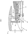
- the outer shroud 44 extends axially over a rotor blade 34 upstream (as shown in FIG. 3 ) and/or downstream of the exit stator 42, defining a tip clearance between the rotor blade 34 and the outer shroud 44.
- exit stator 42 is formed such that the outer shroud 44, the inner shroud 48 and the stator vane 56 together are a unitary component formed by, for example, casting or other manufacturing method.
- the inner shroud 48 includes an axially extending inner shroud tab 64, which fits into a corresponding inner shroud slot 66 in the intermediate case 40 to loosely position the inner shroud 48 in a radial direction. Further, the inner shroud 48 is secured to the intermediate case 40 via a plurality of bolts 68.
- the outer shroud 44 is located in an axial direction via a plurality of radially-extending outer shroud tabs 70 located at a downstream end 72 of the outer shroud 44, which fit into a plurality of outer shroud slots 74 formed in the intermediate case 40.
- outer shroud tabs 70 and the outer shroud slots 74 are circumferentially spaced around the circumference of the outer shroud 44 and the intermediate case 40, respectively, such that the outer shroud tabs 70 are engaged in the outer shroud slots 74 by circumferential rotation of the outer shroud 44 relative to the intermediate case 40.
- the outer shroud 44 is radially and circumferentially located via locating elements of the outer shroud 44 at an upstream end 76 of the outer shroud 44.
- the outer shroud 44 includes a plurality of radial positioning tabs 78 engaged with a plurality of radial pilots 80 protruding radially inwardly from the intermediate case 40.
- the radial pilot 80 includes a sloping pilot lead-in 82, a radial positioning surface 84 and a circumferential stop 86.
- the positioning tab 78 likewise includes a sloping tab lead-in 88 and a radial tab surface 90.
- the radial tab surface 80 is at a greater radial position than the radial positioning surface 84 prior to installation.
- the outer shroud tabs 70 are engaged with the outer shroud slots 74 via rotation of the outer shroud 44 relative to the intermediate case 40.
- the radial positioning tab 78 is engaged with the radial pilot 80 via the rotation of the outer shroud 44 relative to the intermediate case 40, resulting in an interference fit between the radial tab surface 90 and the radial positioning surface 84.
- This engagement between the radial tab surface 90 and the radial positioning surface 84 sets a radial position of the outer shroud 44 in the intermediate case 40.
- the outer shroud 44 may be rotated until the radial positioning tab 78 abuts the circumferential stop 86 thus circumferentially positioning the outer shroud 44 at the intermediate case 40.
- the radial pilot 80 disclosed herein locates and retains the outer shroud 44 of the exit stator 42 in a radial direction and in a circumferential direction through engagement of the radial pilot 80 with the radial positioning tab 78 of the outer shroud 44. Location and retention of the outer shroud 44 prevents a loose fit condition of the outer shroud 44, and thus improves rotor tip clearance control of the exit stator 42. It is to be appreciated that while in the embodiments described herein the radial pilot 80 is located at the outer shroud 44, one skilled in the art will readily appreciate that in other embodiments the radial pilot may be similarly located at the inner shroud 48, or at an intermediate shroud (not shown) extending between adjacent stators 42.
Landscapes
- Engineering & Computer Science (AREA)
- Mechanical Engineering (AREA)
- General Engineering & Computer Science (AREA)
- Turbine Rotor Nozzle Sealing (AREA)
Applications Claiming Priority (1)
| Application Number | Priority Date | Filing Date | Title |
|---|---|---|---|
| US15/136,130 US10450895B2 (en) | 2016-04-22 | 2016-04-22 | Stator arrangement |
Publications (3)
| Publication Number | Publication Date |
|---|---|
| EP3244016A2 true EP3244016A2 (fr) | 2017-11-15 |
| EP3244016A3 EP3244016A3 (fr) | 2018-01-10 |
| EP3244016B1 EP3244016B1 (fr) | 2022-09-07 |
Family
ID=58098558
Family Applications (1)
| Application Number | Title | Priority Date | Filing Date |
|---|---|---|---|
| EP17157103.7A Active EP3244016B1 (fr) | 2016-04-22 | 2017-02-21 | Ensemble stator et carter pour un moteur à turbine à gaz |
Country Status (2)
| Country | Link |
|---|---|
| US (1) | US10450895B2 (fr) |
| EP (1) | EP3244016B1 (fr) |
Cited By (3)
| Publication number | Priority date | Publication date | Assignee | Title |
|---|---|---|---|---|
| EP3611347A1 (fr) * | 2018-08-14 | 2020-02-19 | United Technologies Corporation | Moteur à turbine à gaz doté de segments de stator |
| WO2021084203A1 (fr) * | 2019-10-31 | 2021-05-06 | Safran Aircraft Engines | Turbine de turbomachine a distributeur en cmc avec reprise d'effort |
| EP3910168A1 (fr) * | 2020-05-11 | 2021-11-17 | Raytheon Technologies Corporation | Fabrication unitaire d'un moteur à turbine à gaz |
Families Citing this family (3)
| Publication number | Priority date | Publication date | Assignee | Title |
|---|---|---|---|---|
| DE102016209911A1 (de) * | 2016-06-06 | 2017-12-07 | Man Diesel & Turbo Se | Axialturbine |
| US10808712B2 (en) * | 2018-03-22 | 2020-10-20 | Raytheon Technologies Corporation | Interference fit with high friction material |
| CN114278391B (zh) * | 2021-12-29 | 2024-04-19 | 河北国源电气股份有限公司 | 一种安装紧配的汽轮机用静叶片组 |
Family Cites Families (26)
| Publication number | Priority date | Publication date | Assignee | Title |
|---|---|---|---|---|
| US4249859A (en) * | 1977-12-27 | 1981-02-10 | United Technologies Corporation | Preloaded engine inlet shroud |
| DE3003470C2 (de) * | 1980-01-31 | 1982-02-25 | MTU Motoren- und Turbinen-Union München GmbH, 8000 München | Turbinenleitschaufelaufhängung für Gasturbinenstrahltriebwerke |
| US4687413A (en) * | 1985-07-31 | 1987-08-18 | United Technologies Corporation | Gas turbine engine assembly |
| US4856963A (en) | 1988-03-23 | 1989-08-15 | United Technologies Corporation | Stator assembly for an axial flow rotary machine |
| FR2641573B1 (fr) * | 1989-01-11 | 1991-03-15 | Snecma | Rotor de turbomachine muni d'un dispositif de fixation des aubes |
| US5224824A (en) | 1990-09-12 | 1993-07-06 | United Technologies Corporation | Compressor case construction |
| US5494404A (en) | 1993-12-22 | 1996-02-27 | Alliedsignal Inc. | Insertable stator vane assembly |
| US5584654A (en) * | 1995-12-22 | 1996-12-17 | General Electric Company | Gas turbine engine fan stator |
| FR2800797B1 (fr) * | 1999-11-10 | 2001-12-07 | Snecma | Assemblage d'un anneau bordant une turbine a la structure de turbine |
| US6296443B1 (en) | 1999-12-03 | 2001-10-02 | General Electric Company | Vane sector seating spring and method of retaining same |
| FR2815668B1 (fr) * | 2000-10-19 | 2003-01-10 | Snecma Moteurs | Agencement de liaison d'un anneau de stator de turbine a une entretoise de support |
| US6585479B2 (en) | 2001-08-14 | 2003-07-01 | United Technologies Corporation | Casing treatment for compressors |
| DE10210866C5 (de) * | 2002-03-12 | 2008-04-10 | Mtu Aero Engines Gmbh | Leitschaufelbefestigung in einem Strömungskanal einer Fluggasturbine |
| US7186079B2 (en) * | 2004-11-10 | 2007-03-06 | United Technologies Corporation | Turbine engine disk spacers |
| US7481618B2 (en) * | 2005-12-21 | 2009-01-27 | Rolls-Royce Plc | Mounting arrangement |
| US8092163B2 (en) * | 2008-03-31 | 2012-01-10 | General Electric Company | Turbine stator mount |
| FR2941488B1 (fr) * | 2009-01-28 | 2011-09-16 | Snecma | Anneau de turbine a encoche anti-rotation |
| US8167546B2 (en) | 2009-09-01 | 2012-05-01 | United Technologies Corporation | Ceramic turbine shroud support |
| JP5192507B2 (ja) * | 2010-03-19 | 2013-05-08 | 川崎重工業株式会社 | ガスタービンエンジン |
| US8684674B2 (en) * | 2010-10-29 | 2014-04-01 | General Electric Company | Anti-rotation shroud for turbine engines |
| US10240467B2 (en) | 2012-08-03 | 2019-03-26 | United Technologies Corporation | Anti-rotation lug for a gas turbine engine stator assembly |
| JP5962915B2 (ja) * | 2012-10-29 | 2016-08-03 | 株式会社Ihi | タービンノズルの固定部構造及びこれを用いたタービン |
| US9797262B2 (en) | 2013-07-26 | 2017-10-24 | United Technologies Corporation | Split damped outer shroud for gas turbine engine stator arrays |
| EP3009608B1 (fr) | 2014-10-02 | 2019-10-30 | United Technologies Corporation | Ensemble d'aubes avec des aubes segmentées bloqués |
| US10316749B2 (en) * | 2014-10-20 | 2019-06-11 | United Technologies Corporation | Conduit for guiding low pressure compressor inner diameter shroud motion |
| US10215099B2 (en) * | 2015-02-06 | 2019-02-26 | United Technologies Corporation | System and method for limiting movement of a retainer ring of a gas turbine engine |
-
2016
- 2016-04-22 US US15/136,130 patent/US10450895B2/en active Active
-
2017
- 2017-02-21 EP EP17157103.7A patent/EP3244016B1/fr active Active
Non-Patent Citations (1)
| Title |
|---|
| None |
Cited By (9)
| Publication number | Priority date | Publication date | Assignee | Title |
|---|---|---|---|---|
| EP3611347A1 (fr) * | 2018-08-14 | 2020-02-19 | United Technologies Corporation | Moteur à turbine à gaz doté de segments de stator |
| US11125092B2 (en) | 2018-08-14 | 2021-09-21 | Raytheon Technologies Corporation | Gas turbine engine having cantilevered stators |
| WO2021084203A1 (fr) * | 2019-10-31 | 2021-05-06 | Safran Aircraft Engines | Turbine de turbomachine a distributeur en cmc avec reprise d'effort |
| FR3102795A1 (fr) * | 2019-10-31 | 2021-05-07 | Safran Aircraft Engines | Turbine de turbomachine à distributeur en CMC avec reprise d’effort |
| CN114729574A (zh) * | 2019-10-31 | 2022-07-08 | 赛峰航空器发动机 | 载荷分散的具有cmc喷嘴的涡轮发动机涡轮 |
| US11814990B2 (en) | 2019-10-31 | 2023-11-14 | Safran Aircraft Engines | Turbomachine turbine having a CMC nozzle with load spreading |
| CN114729574B (zh) * | 2019-10-31 | 2024-07-09 | 赛峰航空器发动机 | 载荷分散的具有cmc喷嘴的涡轮发动机涡轮 |
| EP3910168A1 (fr) * | 2020-05-11 | 2021-11-17 | Raytheon Technologies Corporation | Fabrication unitaire d'un moteur à turbine à gaz |
| US11713695B2 (en) | 2020-05-11 | 2023-08-01 | Raytheon Technologies Corporation | Unitized manufacturing of a gas turbine engine |
Also Published As
| Publication number | Publication date |
|---|---|
| US10450895B2 (en) | 2019-10-22 |
| US20170306796A1 (en) | 2017-10-26 |
| EP3244016B1 (fr) | 2022-09-07 |
| EP3244016A3 (fr) | 2018-01-10 |
Similar Documents
| Publication | Publication Date | Title |
|---|---|---|
| EP3244016B1 (fr) | Ensemble stator et carter pour un moteur à turbine à gaz | |
| EP2075411B1 (fr) | Rotor aubagé intégral à moyeu rainuré et moteur à turbine à gaz comprenant un tel rotor | |
| EP3187722B1 (fr) | Admission courte de nacelle pour l'enlèvement de pale de ventilateur | |
| JP5507828B2 (ja) | 非対称流れ抽出システム | |
| EP3187712B1 (fr) | Admission courte de nacelle | |
| EP3299589B1 (fr) | Turbine à gaz | |
| US10907503B2 (en) | Compressors with integrated secondary air flow systems | |
| US20170306768A1 (en) | Turbine engine shroud assembly | |
| EP3170988B1 (fr) | Rotor pour moteur de turbine à gaz | |
| EP2904241B1 (fr) | Dispositif anti-erreur de joint d'étanchéité de chambre de combustion de turbine à gaz | |
| CN107023326B (zh) | 用于在空隙控制系统中使用的歧管及制造方法 | |
| EP3266986A1 (fr) | Ensemble stator segmenté avec masse d'enrobage pour retenir une aube directrice | |
| EP3450692B1 (fr) | Ensemble de joint d'etanceite pour l'interface entre la chambre de combustion et l'aube de stator | |
| US20170198585A1 (en) | Stator rim for a turbine engine | |
| EP3219931B1 (fr) | Agencement d'aube distributrice et moteur à turbine à gaz associé | |
| EP3159503B1 (fr) | Agencement de prélèvement d'air d'un compresseur d'une turbine à gaz et méthode de fabrication d'une section de compresseur de turbine à gaz | |
| CN108870444B (zh) | 燃气涡轮发动机的燃烧器组件 | |
| EP3287605B1 (fr) | Joint de bordure pour moteur à turbine à gaz | |
| US10633992B2 (en) | Rim seal | |
| EP3130751B1 (fr) | Dispositif et procédé de refroidissement d'un rotor d'une turbine à gaz | |
| US11802493B2 (en) | Outlet guide vane assembly in gas turbine engine | |
| US20200240641A1 (en) | Turbomachine, such as an aircraft turbojet engine | |
| US10495111B2 (en) | Compressor stage | |
| US10738638B2 (en) | Rotor blade with wheel space swirlers and method for forming a rotor blade with wheel space swirlers | |
| CN116291759A (zh) | 用于燃气涡轮机组件的导叶及包括其的燃气涡轮机组件 |
Legal Events
| Date | Code | Title | Description |
|---|---|---|---|
| PUAI | Public reference made under article 153(3) epc to a published international application that has entered the european phase |
Free format text: ORIGINAL CODE: 0009012 |
|
| STAA | Information on the status of an ep patent application or granted ep patent |
Free format text: STATUS: THE APPLICATION HAS BEEN PUBLISHED |
|
| AK | Designated contracting states |
Kind code of ref document: A2 Designated state(s): AL AT BE BG CH CY CZ DE DK EE ES FI FR GB GR HR HU IE IS IT LI LT LU LV MC MK MT NL NO PL PT RO RS SE SI SK SM TR |
|
| AX | Request for extension of the european patent |
Extension state: BA ME |
|
| PUAL | Search report despatched |
Free format text: ORIGINAL CODE: 0009013 |
|
| AK | Designated contracting states |
Kind code of ref document: A3 Designated state(s): AL AT BE BG CH CY CZ DE DK EE ES FI FR GB GR HR HU IE IS IT LI LT LU LV MC MK MT NL NO PL PT RO RS SE SI SK SM TR |
|
| AX | Request for extension of the european patent |
Extension state: BA ME |
|
| RIC1 | Information provided on ipc code assigned before grant |
Ipc: F01D 9/04 20060101AFI20171204BHEP |
|
| STAA | Information on the status of an ep patent application or granted ep patent |
Free format text: STATUS: REQUEST FOR EXAMINATION WAS MADE |
|
| 17P | Request for examination filed |
Effective date: 20180710 |
|
| RBV | Designated contracting states (corrected) |
Designated state(s): AL AT BE BG CH CY CZ DE DK EE ES FI FR GB GR HR HU IE IS IT LI LT LU LV MC MK MT NL NO PL PT RO RS SE SI SK SM TR |
|
| STAA | Information on the status of an ep patent application or granted ep patent |
Free format text: STATUS: EXAMINATION IS IN PROGRESS |
|
| 17Q | First examination report despatched |
Effective date: 20200204 |
|
| STAA | Information on the status of an ep patent application or granted ep patent |
Free format text: STATUS: EXAMINATION IS IN PROGRESS |
|
| RAP1 | Party data changed (applicant data changed or rights of an application transferred) |
Owner name: RAYTHEON TECHNOLOGIES CORPORATION |
|
| STAA | Information on the status of an ep patent application or granted ep patent |
Free format text: STATUS: EXAMINATION IS IN PROGRESS |
|
| GRAP | Despatch of communication of intention to grant a patent |
Free format text: ORIGINAL CODE: EPIDOSNIGR1 |
|
| STAA | Information on the status of an ep patent application or granted ep patent |
Free format text: STATUS: GRANT OF PATENT IS INTENDED |
|
| INTG | Intention to grant announced |
Effective date: 20220323 |
|
| RIN1 | Information on inventor provided before grant (corrected) |
Inventor name: AMADON, COLIN G. |
|
| GRAS | Grant fee paid |
Free format text: ORIGINAL CODE: EPIDOSNIGR3 |
|
| GRAA | (expected) grant |
Free format text: ORIGINAL CODE: 0009210 |
|
| STAA | Information on the status of an ep patent application or granted ep patent |
Free format text: STATUS: THE PATENT HAS BEEN GRANTED |
|
| AK | Designated contracting states |
Kind code of ref document: B1 Designated state(s): AL AT BE BG CH CY CZ DE DK EE ES FI FR GB GR HR HU IE IS IT LI LT LU LV MC MK MT NL NO PL PT RO RS SE SI SK SM TR |
|
| REG | Reference to a national code |
Ref country code: GB Ref legal event code: FG4D |
|
| REG | Reference to a national code |
Ref country code: CH Ref legal event code: EP Ref country code: AT Ref legal event code: REF Ref document number: 1517201 Country of ref document: AT Kind code of ref document: T Effective date: 20220915 |
|
| REG | Reference to a national code |
Ref country code: IE Ref legal event code: FG4D |
|
| REG | Reference to a national code |
Ref country code: DE Ref legal event code: R096 Ref document number: 602017061418 Country of ref document: DE |
|
| REG | Reference to a national code |
Ref country code: LT Ref legal event code: MG9D |
|
| REG | Reference to a national code |
Ref country code: NL Ref legal event code: MP Effective date: 20220907 |
|
| PG25 | Lapsed in a contracting state [announced via postgrant information from national office to epo] |
Ref country code: SE Free format text: LAPSE BECAUSE OF FAILURE TO SUBMIT A TRANSLATION OF THE DESCRIPTION OR TO PAY THE FEE WITHIN THE PRESCRIBED TIME-LIMIT Effective date: 20220907 Ref country code: RS Free format text: LAPSE BECAUSE OF FAILURE TO SUBMIT A TRANSLATION OF THE DESCRIPTION OR TO PAY THE FEE WITHIN THE PRESCRIBED TIME-LIMIT Effective date: 20220907 Ref country code: NO Free format text: LAPSE BECAUSE OF FAILURE TO SUBMIT A TRANSLATION OF THE DESCRIPTION OR TO PAY THE FEE WITHIN THE PRESCRIBED TIME-LIMIT Effective date: 20221207 Ref country code: LV Free format text: LAPSE BECAUSE OF FAILURE TO SUBMIT A TRANSLATION OF THE DESCRIPTION OR TO PAY THE FEE WITHIN THE PRESCRIBED TIME-LIMIT Effective date: 20220907 Ref country code: LT Free format text: LAPSE BECAUSE OF FAILURE TO SUBMIT A TRANSLATION OF THE DESCRIPTION OR TO PAY THE FEE WITHIN THE PRESCRIBED TIME-LIMIT Effective date: 20220907 Ref country code: FI Free format text: LAPSE BECAUSE OF FAILURE TO SUBMIT A TRANSLATION OF THE DESCRIPTION OR TO PAY THE FEE WITHIN THE PRESCRIBED TIME-LIMIT Effective date: 20220907 Ref country code: ES Free format text: LAPSE BECAUSE OF FAILURE TO SUBMIT A TRANSLATION OF THE DESCRIPTION OR TO PAY THE FEE WITHIN THE PRESCRIBED TIME-LIMIT Effective date: 20220907 |
|
| REG | Reference to a national code |
Ref country code: AT Ref legal event code: MK05 Ref document number: 1517201 Country of ref document: AT Kind code of ref document: T Effective date: 20220907 |
|
| PG25 | Lapsed in a contracting state [announced via postgrant information from national office to epo] |
Ref country code: HR Free format text: LAPSE BECAUSE OF FAILURE TO SUBMIT A TRANSLATION OF THE DESCRIPTION OR TO PAY THE FEE WITHIN THE PRESCRIBED TIME-LIMIT Effective date: 20220907 Ref country code: GR Free format text: LAPSE BECAUSE OF FAILURE TO SUBMIT A TRANSLATION OF THE DESCRIPTION OR TO PAY THE FEE WITHIN THE PRESCRIBED TIME-LIMIT Effective date: 20221208 |
|
| PG25 | Lapsed in a contracting state [announced via postgrant information from national office to epo] |
Ref country code: SM Free format text: LAPSE BECAUSE OF FAILURE TO SUBMIT A TRANSLATION OF THE DESCRIPTION OR TO PAY THE FEE WITHIN THE PRESCRIBED TIME-LIMIT Effective date: 20220907 Ref country code: RO Free format text: LAPSE BECAUSE OF FAILURE TO SUBMIT A TRANSLATION OF THE DESCRIPTION OR TO PAY THE FEE WITHIN THE PRESCRIBED TIME-LIMIT Effective date: 20220907 Ref country code: PT Free format text: LAPSE BECAUSE OF FAILURE TO SUBMIT A TRANSLATION OF THE DESCRIPTION OR TO PAY THE FEE WITHIN THE PRESCRIBED TIME-LIMIT Effective date: 20230109 Ref country code: CZ Free format text: LAPSE BECAUSE OF FAILURE TO SUBMIT A TRANSLATION OF THE DESCRIPTION OR TO PAY THE FEE WITHIN THE PRESCRIBED TIME-LIMIT Effective date: 20220907 Ref country code: AT Free format text: LAPSE BECAUSE OF FAILURE TO SUBMIT A TRANSLATION OF THE DESCRIPTION OR TO PAY THE FEE WITHIN THE PRESCRIBED TIME-LIMIT Effective date: 20220907 |
|
| PG25 | Lapsed in a contracting state [announced via postgrant information from national office to epo] |
Ref country code: SK Free format text: LAPSE BECAUSE OF FAILURE TO SUBMIT A TRANSLATION OF THE DESCRIPTION OR TO PAY THE FEE WITHIN THE PRESCRIBED TIME-LIMIT Effective date: 20220907 Ref country code: PL Free format text: LAPSE BECAUSE OF FAILURE TO SUBMIT A TRANSLATION OF THE DESCRIPTION OR TO PAY THE FEE WITHIN THE PRESCRIBED TIME-LIMIT Effective date: 20220907 Ref country code: IS Free format text: LAPSE BECAUSE OF FAILURE TO SUBMIT A TRANSLATION OF THE DESCRIPTION OR TO PAY THE FEE WITHIN THE PRESCRIBED TIME-LIMIT Effective date: 20230107 Ref country code: EE Free format text: LAPSE BECAUSE OF FAILURE TO SUBMIT A TRANSLATION OF THE DESCRIPTION OR TO PAY THE FEE WITHIN THE PRESCRIBED TIME-LIMIT Effective date: 20220907 |
|
| REG | Reference to a national code |
Ref country code: DE Ref legal event code: R097 Ref document number: 602017061418 Country of ref document: DE |
|
| P01 | Opt-out of the competence of the unified patent court (upc) registered |
Effective date: 20230520 |
|
| PG25 | Lapsed in a contracting state [announced via postgrant information from national office to epo] |
Ref country code: NL Free format text: LAPSE BECAUSE OF FAILURE TO SUBMIT A TRANSLATION OF THE DESCRIPTION OR TO PAY THE FEE WITHIN THE PRESCRIBED TIME-LIMIT Effective date: 20220907 Ref country code: AL Free format text: LAPSE BECAUSE OF FAILURE TO SUBMIT A TRANSLATION OF THE DESCRIPTION OR TO PAY THE FEE WITHIN THE PRESCRIBED TIME-LIMIT Effective date: 20220907 |
|
| PLBE | No opposition filed within time limit |
Free format text: ORIGINAL CODE: 0009261 |
|
| STAA | Information on the status of an ep patent application or granted ep patent |
Free format text: STATUS: NO OPPOSITION FILED WITHIN TIME LIMIT |
|
| PG25 | Lapsed in a contracting state [announced via postgrant information from national office to epo] |
Ref country code: DK Free format text: LAPSE BECAUSE OF FAILURE TO SUBMIT A TRANSLATION OF THE DESCRIPTION OR TO PAY THE FEE WITHIN THE PRESCRIBED TIME-LIMIT Effective date: 20220907 |
|
| 26N | No opposition filed |
Effective date: 20230608 |
|
| PG25 | Lapsed in a contracting state [announced via postgrant information from national office to epo] |
Ref country code: SI Free format text: LAPSE BECAUSE OF FAILURE TO SUBMIT A TRANSLATION OF THE DESCRIPTION OR TO PAY THE FEE WITHIN THE PRESCRIBED TIME-LIMIT Effective date: 20220907 |
|
| PG25 | Lapsed in a contracting state [announced via postgrant information from national office to epo] |
Ref country code: MC Free format text: LAPSE BECAUSE OF FAILURE TO SUBMIT A TRANSLATION OF THE DESCRIPTION OR TO PAY THE FEE WITHIN THE PRESCRIBED TIME-LIMIT Effective date: 20220907 |
|
| REG | Reference to a national code |
Ref country code: CH Ref legal event code: PL |
|
| REG | Reference to a national code |
Ref country code: BE Ref legal event code: MM Effective date: 20230228 |
|
| PG25 | Lapsed in a contracting state [announced via postgrant information from national office to epo] |
Ref country code: LU Free format text: LAPSE BECAUSE OF NON-PAYMENT OF DUE FEES Effective date: 20230221 Ref country code: LI Free format text: LAPSE BECAUSE OF NON-PAYMENT OF DUE FEES Effective date: 20230228 Ref country code: CH Free format text: LAPSE BECAUSE OF NON-PAYMENT OF DUE FEES Effective date: 20230228 |
|
| REG | Reference to a national code |
Ref country code: IE Ref legal event code: MM4A |
|
| PG25 | Lapsed in a contracting state [announced via postgrant information from national office to epo] |
Ref country code: IE Free format text: LAPSE BECAUSE OF NON-PAYMENT OF DUE FEES Effective date: 20230221 |
|
| PG25 | Lapsed in a contracting state [announced via postgrant information from national office to epo] |
Ref country code: BE Free format text: LAPSE BECAUSE OF NON-PAYMENT OF DUE FEES Effective date: 20230228 |
|
| PGFP | Annual fee paid to national office [announced via postgrant information from national office to epo] |
Ref country code: DE Payment date: 20240123 Year of fee payment: 8 Ref country code: GB Payment date: 20240123 Year of fee payment: 8 |
|
| PG25 | Lapsed in a contracting state [announced via postgrant information from national office to epo] |
Ref country code: IT Free format text: LAPSE BECAUSE OF FAILURE TO SUBMIT A TRANSLATION OF THE DESCRIPTION OR TO PAY THE FEE WITHIN THE PRESCRIBED TIME-LIMIT Effective date: 20220907 |
|
| PGFP | Annual fee paid to national office [announced via postgrant information from national office to epo] |
Ref country code: FR Payment date: 20240123 Year of fee payment: 8 |