EP3219931B1 - Agencement d'aube distributrice et moteur à turbine à gaz associé - Google Patents
Agencement d'aube distributrice et moteur à turbine à gaz associé Download PDFInfo
- Publication number
- EP3219931B1 EP3219931B1 EP17161678.2A EP17161678A EP3219931B1 EP 3219931 B1 EP3219931 B1 EP 3219931B1 EP 17161678 A EP17161678 A EP 17161678A EP 3219931 B1 EP3219931 B1 EP 3219931B1
- Authority
- EP
- European Patent Office
- Prior art keywords
- vane
- retainer
- gas turbine
- turbine engine
- bushing
- Prior art date
- Legal status (The legal status is an assumption and is not a legal conclusion. Google has not performed a legal analysis and makes no representation as to the accuracy of the status listed.)
- Active
Links
- 238000009434 installation Methods 0.000 claims description 13
- 230000000712 assembly Effects 0.000 claims description 2
- 238000000429 assembly Methods 0.000 claims description 2
- 239000012530 fluid Substances 0.000 claims description 2
- 230000000295 complement effect Effects 0.000 claims 3
- 239000007789 gas Substances 0.000 description 15
- 230000014759 maintenance of location Effects 0.000 description 4
- 239000003570 air Substances 0.000 description 3
- 239000000567 combustion gas Substances 0.000 description 2
- 239000000446 fuel Substances 0.000 description 2
- 238000011144 upstream manufacturing Methods 0.000 description 2
- 241000237503 Pectinidae Species 0.000 description 1
- 239000012080 ambient air Substances 0.000 description 1
- 238000012423 maintenance Methods 0.000 description 1
- 239000000463 material Substances 0.000 description 1
- 239000011369 resultant mixture Substances 0.000 description 1
- 230000000717 retained effect Effects 0.000 description 1
- 235000020637 scallop Nutrition 0.000 description 1
Images

Classifications
-
- F—MECHANICAL ENGINEERING; LIGHTING; HEATING; WEAPONS; BLASTING
- F01—MACHINES OR ENGINES IN GENERAL; ENGINE PLANTS IN GENERAL; STEAM ENGINES
- F01D—NON-POSITIVE DISPLACEMENT MACHINES OR ENGINES, e.g. STEAM TURBINES
- F01D9/00—Stators
- F01D9/02—Nozzles; Nozzle boxes; Stator blades; Guide conduits, e.g. individual nozzles
- F01D9/04—Nozzles; Nozzle boxes; Stator blades; Guide conduits, e.g. individual nozzles forming ring or sector
- F01D9/042—Nozzles; Nozzle boxes; Stator blades; Guide conduits, e.g. individual nozzles forming ring or sector fixing blades to stators
-
- F—MECHANICAL ENGINEERING; LIGHTING; HEATING; WEAPONS; BLASTING
- F01—MACHINES OR ENGINES IN GENERAL; ENGINE PLANTS IN GENERAL; STEAM ENGINES
- F01D—NON-POSITIVE DISPLACEMENT MACHINES OR ENGINES, e.g. STEAM TURBINES
- F01D17/00—Regulating or controlling by varying flow
- F01D17/10—Final actuators
- F01D17/12—Final actuators arranged in stator parts
- F01D17/14—Final actuators arranged in stator parts varying effective cross-sectional area of nozzles or guide conduits
- F01D17/16—Final actuators arranged in stator parts varying effective cross-sectional area of nozzles or guide conduits by means of nozzle vanes
- F01D17/162—Final actuators arranged in stator parts varying effective cross-sectional area of nozzles or guide conduits by means of nozzle vanes for axial flow, i.e. the vanes turning around axes which are essentially perpendicular to the rotor centre line
-
- F—MECHANICAL ENGINEERING; LIGHTING; HEATING; WEAPONS; BLASTING
- F02—COMBUSTION ENGINES; HOT-GAS OR COMBUSTION-PRODUCT ENGINE PLANTS
- F02C—GAS-TURBINE PLANTS; AIR INTAKES FOR JET-PROPULSION PLANTS; CONTROLLING FUEL SUPPLY IN AIR-BREATHING JET-PROPULSION PLANTS
- F02C9/00—Controlling gas-turbine plants; Controlling fuel supply in air- breathing jet-propulsion plants
- F02C9/16—Control of working fluid flow
- F02C9/20—Control of working fluid flow by throttling; by adjusting vanes
-
- F—MECHANICAL ENGINEERING; LIGHTING; HEATING; WEAPONS; BLASTING
- F04—POSITIVE - DISPLACEMENT MACHINES FOR LIQUIDS; PUMPS FOR LIQUIDS OR ELASTIC FLUIDS
- F04D—NON-POSITIVE-DISPLACEMENT PUMPS
- F04D29/00—Details, component parts, or accessories
- F04D29/26—Rotors specially for elastic fluids
- F04D29/32—Rotors specially for elastic fluids for axial flow pumps
- F04D29/321—Rotors specially for elastic fluids for axial flow pumps for axial flow compressors
- F04D29/322—Blade mountings
- F04D29/323—Blade mountings adjustable
-
- F—MECHANICAL ENGINEERING; LIGHTING; HEATING; WEAPONS; BLASTING
- F04—POSITIVE - DISPLACEMENT MACHINES FOR LIQUIDS; PUMPS FOR LIQUIDS OR ELASTIC FLUIDS
- F04D—NON-POSITIVE-DISPLACEMENT PUMPS
- F04D29/00—Details, component parts, or accessories
- F04D29/40—Casings; Connections of working fluid
- F04D29/52—Casings; Connections of working fluid for axial pumps
- F04D29/54—Fluid-guiding means, e.g. diffusers
-
- F—MECHANICAL ENGINEERING; LIGHTING; HEATING; WEAPONS; BLASTING
- F05—INDEXING SCHEMES RELATING TO ENGINES OR PUMPS IN VARIOUS SUBCLASSES OF CLASSES F01-F04
- F05D—INDEXING SCHEME FOR ASPECTS RELATING TO NON-POSITIVE-DISPLACEMENT MACHINES OR ENGINES, GAS-TURBINES OR JET-PROPULSION PLANTS
- F05D2220/00—Application
- F05D2220/30—Application in turbines
- F05D2220/32—Application in turbines in gas turbines
- F05D2220/321—Application in turbines in gas turbines for a special turbine stage
- F05D2220/3216—Application in turbines in gas turbines for a special turbine stage for a special compressor stage
- F05D2220/3217—Application in turbines in gas turbines for a special turbine stage for a special compressor stage for the first stage of a compressor or a low pressure compressor
-
- F—MECHANICAL ENGINEERING; LIGHTING; HEATING; WEAPONS; BLASTING
- F05—INDEXING SCHEMES RELATING TO ENGINES OR PUMPS IN VARIOUS SUBCLASSES OF CLASSES F01-F04
- F05D—INDEXING SCHEME FOR ASPECTS RELATING TO NON-POSITIVE-DISPLACEMENT MACHINES OR ENGINES, GAS-TURBINES OR JET-PROPULSION PLANTS
- F05D2240/00—Components
- F05D2240/10—Stators
- F05D2240/12—Fluid guiding means, e.g. vanes
-
- F—MECHANICAL ENGINEERING; LIGHTING; HEATING; WEAPONS; BLASTING
- F05—INDEXING SCHEMES RELATING TO ENGINES OR PUMPS IN VARIOUS SUBCLASSES OF CLASSES F01-F04
- F05D—INDEXING SCHEME FOR ASPECTS RELATING TO NON-POSITIVE-DISPLACEMENT MACHINES OR ENGINES, GAS-TURBINES OR JET-PROPULSION PLANTS
- F05D2240/00—Components
- F05D2240/10—Stators
- F05D2240/14—Casings or housings protecting or supporting assemblies within
-
- F—MECHANICAL ENGINEERING; LIGHTING; HEATING; WEAPONS; BLASTING
- F05—INDEXING SCHEMES RELATING TO ENGINES OR PUMPS IN VARIOUS SUBCLASSES OF CLASSES F01-F04
- F05D—INDEXING SCHEME FOR ASPECTS RELATING TO NON-POSITIVE-DISPLACEMENT MACHINES OR ENGINES, GAS-TURBINES OR JET-PROPULSION PLANTS
- F05D2250/00—Geometry
- F05D2250/10—Two-dimensional
- F05D2250/18—Two-dimensional patterned
- F05D2250/181—Two-dimensional patterned ridged
-
- F—MECHANICAL ENGINEERING; LIGHTING; HEATING; WEAPONS; BLASTING
- F05—INDEXING SCHEMES RELATING TO ENGINES OR PUMPS IN VARIOUS SUBCLASSES OF CLASSES F01-F04
- F05D—INDEXING SCHEME FOR ASPECTS RELATING TO NON-POSITIVE-DISPLACEMENT MACHINES OR ENGINES, GAS-TURBINES OR JET-PROPULSION PLANTS
- F05D2250/00—Geometry
- F05D2250/10—Two-dimensional
- F05D2250/18—Two-dimensional patterned
- F05D2250/182—Two-dimensional patterned crenellated, notched
-
- F—MECHANICAL ENGINEERING; LIGHTING; HEATING; WEAPONS; BLASTING
- F05—INDEXING SCHEMES RELATING TO ENGINES OR PUMPS IN VARIOUS SUBCLASSES OF CLASSES F01-F04
- F05D—INDEXING SCHEME FOR ASPECTS RELATING TO NON-POSITIVE-DISPLACEMENT MACHINES OR ENGINES, GAS-TURBINES OR JET-PROPULSION PLANTS
- F05D2260/00—Function
- F05D2260/30—Retaining components in desired mutual position
- F05D2260/31—Retaining bolts or nuts
Definitions
- This disclosure relates to gas turbine engines, and more particularly to retention of vanes of gas turbine engines.
- Typical gas turbine engines utilize one or more stages of variable vanes, vanes which are rotatable about a vane axis to vary an angle of attack relative to an airstream flowing across the vane, and to vary a turning angle the variable vane applies to the airstream to change an angle of incidence of the airstream on components downstream of the variable vanes, for example, a fan rotor or compressor rotor.
- Each vane is typically retained at a case surrounding the vane stage, with the vanes rotatably secured to allow for rotation of the vanes about the vane axis.
- installation of conventional vane retention components at the outer surface of the case can be difficult. Often, compromises are made in the configuration of the case outer surface, such as scallops formed into flanges or the like, to allow for necessary clearance for the vane retention components and their associated installation tools to be utilized to retain the vanes as required.
- US 2002/182064 A1 discloses an angular positioning and synchronising unit for rotating vanes.
- a lever of the unit is fixed to a vane by means of a locking ring screwed to a threaded section.
- the present invention provides a vane assembly for a gas turbine engine according to claim 1.
- the plurality of castellations are equally spaced about a vane retainer axis.
- a castellation height is substantially equal to a castellation width.
- a chamfer is located at a top surface of the castellation.
- a fillet is located at a castellation base.
- the plurality of castellations is eight equally sized castellations.
- the vane stem defines an axis of rotation of the vane.
- a gas turbine engine includes a combustor and a plurality of vane assemblies in fluid communication with the combustor.
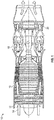
- FIG. 1 is a schematic illustration of a gas turbine engine 10.
- the gas turbine engine generally has a fan 12 through which ambient air is propelled in the direction of arrow 14, a compressor 16 for pressurizing the air received from the fan 12 and a combustor 18 wherein the compressed air is mixed with fuel and ignited for generating combustion gases.
- the gas turbine engine 10 further comprises a turbine section 20 for extracting energy from the combustion gases. Fuel is injected into the combustor 18 of the gas turbine engine 10 for mixing with the compressed air from the compressor 16 and ignition of the resultant mixture.
- the fan 12, compressor 16, combustor 18, and turbine 20 are typically all concentric about a common central longitudinal axis of the gas turbine engine 10.
- the gas turbine engine 10 may further comprise a low pressure compressor located upstream of a high pressure compressor and a high pressure turbine located upstream of a low pressure turbine.
- the compressor 16 may be a multi-stage compressor 16 that has a low-pressure compressor and a high-pressure compressor and the turbine 20 may be a multistage turbine 20 that has a high-pressure turbine and a low-pressure turbine.
- the low-pressure compressor is connected to the low-pressure turbine and the high pressure compressor is connected to the high-pressure turbine.
- the gas turbine engine 10 may include one or more stages of variable vanes located at, for example, the fan 12 or compressor 16.
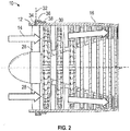
- the fan 12 may include a plurality of variable vanes 28.
- the variable vanes 28 are rotatable secured in a fan case 30, or other case or component, and are each rotatable about a vane axis 32 to vary an angle of incidence of airflow to downstream components, such as fan rotors (not shown).
- the variable vanes 28 are each connected to a vane arm 34 and a vane linkage 36, which is driven by a vane actuator 38 to urge rotation of the variable vanes 28 about the vane axis 32 to a selected position. While the embodiments described herein relate to variable vanes 28 located at fan case 30, it is to be appreciated that the present disclosure may be readily applied to other vanes of gas turbine engine 10, such as compressor vanes or turbine vanes.
- the fan case 30 includes two or more circumferential fan case sections 40 secured to one another to form a full fan case 30.
- Each fan case section 40 has a case flange 42 which abuts another case flange 42 of an adjacent fan case section 40, with the case flanges 42 secured to one another via, for example, a bolted connection (not shown).
- Variable vanes 28 are spaced circumferentially around the fan case 30, and in some configurations variable vanes 28 are positioned at locations, such as near case flanges 42, where clearance between the case flange 42 and a vane retainer 44, used to secure the variable vane 28 in place, is small.
- the case flange is thinned or even notched to increase clearance for the vane retainer and its associated installation tool.
- the thinning and/or notching of the fan case flange or other fan case features to accommodate a typical vane retainer arrangement often requires a more robust material be used for the fan case and/or other features added to the fan case so the fan case meets service life requirements.
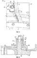
- vane retainer 44 requires that no such concessions be made. Rather than using features at an outer diameter of the vane retainer as tool engagement surfaces for installation of the vane retainer, vane retainer 44 includes a plurality of castellations 46 located at a retainer end 48 as tool engagement surfaces.
- the variable vane 28 includes an airfoil portion 50 and a vane stem 52 extending radially outwardly from the airfoil portion 50. The vane stem 52 is inserted into a bushing 56, with the bushing 56 inserted into and extending through a vane opening 58 in the fan case 30.
- the vane stem 52 is positioned in the bushing 56 so that the vane stem 52 is free to rotate relative to the bushing 56.
- the vane retainer 44 is then installed over the bushing 56 such that retainer threads 60 at an inner retainer surface 62 engage with bushing threads 64 at an outer bushing surface 66 to secure the bushing 56 and the variable vane 28 to the fan case 30.
- a wedge lock washer 68 may be installed at a retainer base 70 of the vane retainer 44 to prevent loosening of the vane retainer 44 once the vane retainer 44 is installed.
- a helical coil insert 72 located in the vane stem 52 is utilized for installation of a vane arm 34 at the variable vane 28.
- the plurality of castellations 46 located at the retainer end 48 are utilized as tool engagement surfaces for installation of the vane retainer 44 to the bushing 56.
- the plurality of castellations 46 engage with a plurality of complimentary tool features 74 of an installation tool 76 to drive rotation of the vane retainer 44 and urge the vane retainer 44 into engagement with the bushing 56.
- the vane retainer 44 includes a retainer body 98 and eight equally-sized castellations 46 equally spaced about a vane retainer axis 78. Further, the castellations 46 may be configured and arranged such that a first angle 80 described by each castellation 46 is equal to a second angle 82 between adjacent castellations 46. In the embodiment shown having eight castellations 46, the first angle 80 and the second angle 82 are about 22.5 degrees. While the vane retainer 44 shown in FIG. 6 has eight castellations 46, it is to be appreciated that other numbers of castellations 46 may be utilized in other embodiments, for example, 4, 12, 18 or 24 castellations 46.
- a castellation height 84 may be equal to a castellation width 86, defined at an outer surface of the vane retainer 44. In other embodiments, however, the castellation height 84 may be greater than or less than the castellation width 86. Further, a top portion 90 of each castellation 46 may include a chamfer 92 to facilitate engagement with the tool features 74, and base 94 of each castellation 46 may include a fillet 96 to reduce stresses on the castellation 46 which may lead to castellation 46 breakage.
- the vane retainer 44 disclosed herein allows for installation of vanes near to case flanges or other features without the need to modify or eliminate such case features to provide installation tool clearance for installation of the vane retainer. This allows for maintenance of the intended structural or performance integrity of the case without needing to further modify the case or the vane design or arrangement.
Landscapes
- Engineering & Computer Science (AREA)
- Mechanical Engineering (AREA)
- General Engineering & Computer Science (AREA)
- Chemical & Material Sciences (AREA)
- Combustion & Propulsion (AREA)
- Physics & Mathematics (AREA)
- Fluid Mechanics (AREA)
- Structures Of Non-Positive Displacement Pumps (AREA)
- Turbine Rotor Nozzle Sealing (AREA)
Claims (9)
- Agencement d'aube distributrice pour un moteur à turbine à gaz, comprenant :une aube (28) ayant :une partie de profil aérodynamique (50) ; etune tige d'aube (52) s'étendant depuis la partie de profil aérodynamique (50) ;une douille (56) dans laquelle la tige d'aube (52) est insérée ; etun dispositif de retenue d'aube (44) ayant :un corps de retenue (98) ;une surface intérieure filetée (62) du corps de retenue (98) mettant en prise des filets complémentaires de la douille (56) ; etune pluralité de créneaux (46) disposés à une extrémité distale du corps de retenue (98) pour une venue en prise avec des éléments complémentaires d'outil d'installation (74) pendant l'installation du dispositif de retenue d'aube (44) sur la douille (56) pour retenir l'aube (28) à un carter (30).
- Agencement d'aube distributrice selon la revendication 1, dans lequel la pluralité de créneaux (46) sont espacés de manière égale autour d'un axe de retenue d'aube (78).
- Agencement d'aube distributrice selon la revendication 1, dans lequel une hauteur de créneau (84) est sensiblement égale à une largeur de créneau (86).
- Agencement d'aube distributrice selon la revendication 1, comprenant en outre un chanfrein (92) disposé sur une surface supérieure (90) du créneau (46).
- Agencement d'aube distributrice selon la revendication 1, comprenant en outre un filet (96) disposé au niveau d'une base de créneau (94).
- Agencement d'aube distributrice selon la revendication 1, dans lequel la pluralité de créneaux (46) correspond à huit créneaux de taille égale.
- Agencement d'aube distributrice selon la revendication 1, dans lequel la tige d'aube (52) définit un axe de rotation de l'aube (28).
- Moteur à turbine à gaz (10), comprenant :une chambre de combustion (18) ; etune pluralité d'agencements d'aube distributrice selon l'une quelconque des revendications 1 à 7 en communication fluidique avec la chambre de combustion (18).
- Moteur à turbine à gaz (10) selon la revendication 8, comprenant en outre un carter (30), la surface intérieure filetée (62) de chaque corps de retenue (90) mettant en prise les filets complémentaires de la douille respective (56) pour fixer la douille (56) et l'aube (28) au carter (30).
Applications Claiming Priority (1)
| Application Number | Priority Date | Filing Date | Title |
|---|---|---|---|
| US15/073,008 US10502077B2 (en) | 2016-03-17 | 2016-03-17 | Vane retainer |
Publications (2)
| Publication Number | Publication Date |
|---|---|
| EP3219931A1 EP3219931A1 (fr) | 2017-09-20 |
| EP3219931B1 true EP3219931B1 (fr) | 2021-06-02 |
Family
ID=58358505
Family Applications (1)
| Application Number | Title | Priority Date | Filing Date |
|---|---|---|---|
| EP17161678.2A Active EP3219931B1 (fr) | 2016-03-17 | 2017-03-17 | Agencement d'aube distributrice et moteur à turbine à gaz associé |
Country Status (2)
| Country | Link |
|---|---|
| US (1) | US10502077B2 (fr) |
| EP (1) | EP3219931B1 (fr) |
Families Citing this family (3)
| Publication number | Priority date | Publication date | Assignee | Title |
|---|---|---|---|---|
| US10495108B2 (en) * | 2017-01-31 | 2019-12-03 | Honeywell International Inc. | Variable vane devices containing rotationally-driven translating vane structures and methods for the production thereof |
| US10458419B2 (en) * | 2017-03-01 | 2019-10-29 | Air Cool Industrial Co., Ltd. | Transmission device of fan |
| DE102022102421A1 (de) * | 2022-02-02 | 2023-08-03 | MTU Aero Engines AG | Schaufelanordnung für eine strömungsmaschine |
Family Cites Families (10)
| Publication number | Priority date | Publication date | Assignee | Title |
|---|---|---|---|---|
| US3269701A (en) | 1963-10-17 | 1966-08-30 | Carrier Corp | Stator blade support |
| US4245954A (en) | 1978-12-01 | 1981-01-20 | Westinghouse Electric Corp. | Ceramic turbine stator vane and shroud support |
| US4307994A (en) * | 1979-10-15 | 1981-12-29 | General Motors Corporation | Variable vane position adjuster |
| FR2556410B1 (fr) * | 1983-12-07 | 1986-09-12 | Snecma | Dispositif de centrage de l'anneau interieur d'un stator a ailettes a calage variable |
| FR2685033B1 (fr) * | 1991-12-11 | 1994-02-11 | Snecma | Stator dirigeant l'entree de l'air a l'interieur d'une turbomachine et procede de montage d'une aube de ce stator. |
| GB9928256D0 (en) * | 1999-11-30 | 2000-01-26 | Smiths Industries Plc | Electrical couplings,connectors and components |
| ITTO20010444A1 (it) * | 2001-05-11 | 2002-11-11 | Fiatavio Spa | Turbina assiale per applicazioni aeronautiche. |
| GB2402179B (en) * | 2003-05-27 | 2006-02-22 | Rolls Royce Plc | A variable vane arrangement for a turbomachine |
| GB0312098D0 (en) * | 2003-05-27 | 2004-05-05 | Rolls Royce Plc | A variable arrangement for a turbomachine |
| US9879560B2 (en) | 2015-05-15 | 2018-01-30 | United Technologies Corporation | Vane strut positioning and securing systems |
-
2016
- 2016-03-17 US US15/073,008 patent/US10502077B2/en active Active
-
2017
- 2017-03-17 EP EP17161678.2A patent/EP3219931B1/fr active Active
Non-Patent Citations (1)
| Title |
|---|
| None * |
Also Published As
| Publication number | Publication date |
|---|---|
| US10502077B2 (en) | 2019-12-10 |
| EP3219931A1 (fr) | 2017-09-20 |
| US20170268357A1 (en) | 2017-09-21 |
Similar Documents
| Publication | Publication Date | Title |
|---|---|---|
| US7011494B2 (en) | Dual retention vane arm | |
| US7588415B2 (en) | Synch ring variable vane synchronizing mechanism for inner diameter vane shroud | |
| US9151178B2 (en) | Bellcrank for a variable vane assembly | |
| US9145776B2 (en) | Retention device for a rotating blade | |
| US8985961B2 (en) | Turbomachine rotor comprising an anti-wear plug, and anti-wear plug | |
| EP3219931B1 (fr) | Agencement d'aube distributrice et moteur à turbine à gaz associé | |
| EP3299589B1 (fr) | Turbine à gaz | |
| US9518471B2 (en) | Locking spacer assembly | |
| US10450895B2 (en) | Stator arrangement | |
| EP3343002B1 (fr) | Carter pour turbine à gaz et turbine à gaz | |
| US20170254342A1 (en) | Asymmetric alignment system for a variable stator vane | |
| EP3722564B1 (fr) | Agencement de levier d'aube directrice pour moteur à turbine à gaz, procéde de rétention axiale redondante d'un levier d'aube directrice et moteur à turbine à gaz associés | |
| US9644491B2 (en) | Single bolting flange arrangement for variable guide vane connection | |
| EP2549060B1 (fr) | Verrouillage d'aubes dans une rainure de fixation tangentielle d'un rotor | |
| US10648359B2 (en) | System for controlling variable-setting blades for a turbine engine | |
| CN110872955A (zh) | 涡轮发动机中的可变喷嘴及其相关方法 | |
| US6773228B2 (en) | Methods and apparatus for turbine nozzle locks | |
| EP2594751A2 (fr) | Retenue de goujon | |
| EP3006694B1 (fr) | Turbine, turbocompresseur, moteur à combustion interne, et navire | |
| EP4063617B1 (fr) | Ensemble de retenue avec fonction anti-rotation |
Legal Events
| Date | Code | Title | Description |
|---|---|---|---|
| PUAI | Public reference made under article 153(3) epc to a published international application that has entered the european phase |
Free format text: ORIGINAL CODE: 0009012 |
|
| STAA | Information on the status of an ep patent application or granted ep patent |
Free format text: STATUS: THE APPLICATION HAS BEEN PUBLISHED |
|
| AK | Designated contracting states |
Kind code of ref document: A1 Designated state(s): AL AT BE BG CH CY CZ DE DK EE ES FI FR GB GR HR HU IE IS IT LI LT LU LV MC MK MT NL NO PL PT RO RS SE SI SK SM TR |
|
| AX | Request for extension of the european patent |
Extension state: BA ME |
|
| STAA | Information on the status of an ep patent application or granted ep patent |
Free format text: STATUS: REQUEST FOR EXAMINATION WAS MADE |
|
| 17P | Request for examination filed |
Effective date: 20180320 |
|
| RBV | Designated contracting states (corrected) |
Designated state(s): AL AT BE BG CH CY CZ DE DK EE ES FI FR GB GR HR HU IE IS IT LI LT LU LV MC MK MT NL NO PL PT RO RS SE SI SK SM TR |
|
| GRAP | Despatch of communication of intention to grant a patent |
Free format text: ORIGINAL CODE: EPIDOSNIGR1 |
|
| STAA | Information on the status of an ep patent application or granted ep patent |
Free format text: STATUS: GRANT OF PATENT IS INTENDED |
|
| INTG | Intention to grant announced |
Effective date: 20201215 |
|
| RAP1 | Party data changed (applicant data changed or rights of an application transferred) |
Owner name: RAYTHEON TECHNOLOGIES CORPORATION |
|
| GRAS | Grant fee paid |
Free format text: ORIGINAL CODE: EPIDOSNIGR3 |
|
| GRAA | (expected) grant |
Free format text: ORIGINAL CODE: 0009210 |
|
| STAA | Information on the status of an ep patent application or granted ep patent |
Free format text: STATUS: THE PATENT HAS BEEN GRANTED |
|
| REG | Reference to a national code |
Ref country code: CH Ref legal event code: EP |
|
| AK | Designated contracting states |
Kind code of ref document: B1 Designated state(s): AL AT BE BG CH CY CZ DE DK EE ES FI FR GB GR HR HU IE IS IT LI LT LU LV MC MK MT NL NO PL PT RO RS SE SI SK SM TR |
|
| REG | Reference to a national code |
Ref country code: GB Ref legal event code: FG4D |
|
| REG | Reference to a national code |
Ref country code: AT Ref legal event code: REF Ref document number: 1398608 Country of ref document: AT Kind code of ref document: T Effective date: 20210615 |
|
| REG | Reference to a national code |
Ref country code: IE Ref legal event code: FG4D |
|
| REG | Reference to a national code |
Ref country code: DE Ref legal event code: R096 Ref document number: 602017039535 Country of ref document: DE |
|
| REG | Reference to a national code |
Ref country code: LT Ref legal event code: MG9D |
|
| PG25 | Lapsed in a contracting state [announced via postgrant information from national office to epo] |
Ref country code: HR Free format text: LAPSE BECAUSE OF FAILURE TO SUBMIT A TRANSLATION OF THE DESCRIPTION OR TO PAY THE FEE WITHIN THE PRESCRIBED TIME-LIMIT Effective date: 20210602 Ref country code: BG Free format text: LAPSE BECAUSE OF FAILURE TO SUBMIT A TRANSLATION OF THE DESCRIPTION OR TO PAY THE FEE WITHIN THE PRESCRIBED TIME-LIMIT Effective date: 20210902 Ref country code: FI Free format text: LAPSE BECAUSE OF FAILURE TO SUBMIT A TRANSLATION OF THE DESCRIPTION OR TO PAY THE FEE WITHIN THE PRESCRIBED TIME-LIMIT Effective date: 20210602 Ref country code: LT Free format text: LAPSE BECAUSE OF FAILURE TO SUBMIT A TRANSLATION OF THE DESCRIPTION OR TO PAY THE FEE WITHIN THE PRESCRIBED TIME-LIMIT Effective date: 20210602 |
|
| REG | Reference to a national code |
Ref country code: NL Ref legal event code: MP Effective date: 20210602 |
|
| REG | Reference to a national code |
Ref country code: AT Ref legal event code: MK05 Ref document number: 1398608 Country of ref document: AT Kind code of ref document: T Effective date: 20210602 |
|
| PG25 | Lapsed in a contracting state [announced via postgrant information from national office to epo] |
Ref country code: LV Free format text: LAPSE BECAUSE OF FAILURE TO SUBMIT A TRANSLATION OF THE DESCRIPTION OR TO PAY THE FEE WITHIN THE PRESCRIBED TIME-LIMIT Effective date: 20210602 Ref country code: GR Free format text: LAPSE BECAUSE OF FAILURE TO SUBMIT A TRANSLATION OF THE DESCRIPTION OR TO PAY THE FEE WITHIN THE PRESCRIBED TIME-LIMIT Effective date: 20210903 Ref country code: NO Free format text: LAPSE BECAUSE OF FAILURE TO SUBMIT A TRANSLATION OF THE DESCRIPTION OR TO PAY THE FEE WITHIN THE PRESCRIBED TIME-LIMIT Effective date: 20210902 Ref country code: PL Free format text: LAPSE BECAUSE OF FAILURE TO SUBMIT A TRANSLATION OF THE DESCRIPTION OR TO PAY THE FEE WITHIN THE PRESCRIBED TIME-LIMIT Effective date: 20210602 Ref country code: SE Free format text: LAPSE BECAUSE OF FAILURE TO SUBMIT A TRANSLATION OF THE DESCRIPTION OR TO PAY THE FEE WITHIN THE PRESCRIBED TIME-LIMIT Effective date: 20210602 Ref country code: RS Free format text: LAPSE BECAUSE OF FAILURE TO SUBMIT A TRANSLATION OF THE DESCRIPTION OR TO PAY THE FEE WITHIN THE PRESCRIBED TIME-LIMIT Effective date: 20210602 |
|
| PG25 | Lapsed in a contracting state [announced via postgrant information from national office to epo] |
Ref country code: SK Free format text: LAPSE BECAUSE OF FAILURE TO SUBMIT A TRANSLATION OF THE DESCRIPTION OR TO PAY THE FEE WITHIN THE PRESCRIBED TIME-LIMIT Effective date: 20210602 Ref country code: SM Free format text: LAPSE BECAUSE OF FAILURE TO SUBMIT A TRANSLATION OF THE DESCRIPTION OR TO PAY THE FEE WITHIN THE PRESCRIBED TIME-LIMIT Effective date: 20210602 Ref country code: AT Free format text: LAPSE BECAUSE OF FAILURE TO SUBMIT A TRANSLATION OF THE DESCRIPTION OR TO PAY THE FEE WITHIN THE PRESCRIBED TIME-LIMIT Effective date: 20210602 Ref country code: CZ Free format text: LAPSE BECAUSE OF FAILURE TO SUBMIT A TRANSLATION OF THE DESCRIPTION OR TO PAY THE FEE WITHIN THE PRESCRIBED TIME-LIMIT Effective date: 20210602 Ref country code: EE Free format text: LAPSE BECAUSE OF FAILURE TO SUBMIT A TRANSLATION OF THE DESCRIPTION OR TO PAY THE FEE WITHIN THE PRESCRIBED TIME-LIMIT Effective date: 20210602 Ref country code: NL Free format text: LAPSE BECAUSE OF FAILURE TO SUBMIT A TRANSLATION OF THE DESCRIPTION OR TO PAY THE FEE WITHIN THE PRESCRIBED TIME-LIMIT Effective date: 20210602 Ref country code: RO Free format text: LAPSE BECAUSE OF FAILURE TO SUBMIT A TRANSLATION OF THE DESCRIPTION OR TO PAY THE FEE WITHIN THE PRESCRIBED TIME-LIMIT Effective date: 20210602 Ref country code: PT Free format text: LAPSE BECAUSE OF FAILURE TO SUBMIT A TRANSLATION OF THE DESCRIPTION OR TO PAY THE FEE WITHIN THE PRESCRIBED TIME-LIMIT Effective date: 20211004 Ref country code: ES Free format text: LAPSE BECAUSE OF FAILURE TO SUBMIT A TRANSLATION OF THE DESCRIPTION OR TO PAY THE FEE WITHIN THE PRESCRIBED TIME-LIMIT Effective date: 20210602 |
|
| REG | Reference to a national code |
Ref country code: DE Ref legal event code: R097 Ref document number: 602017039535 Country of ref document: DE |
|
| PLBE | No opposition filed within time limit |
Free format text: ORIGINAL CODE: 0009261 |
|
| STAA | Information on the status of an ep patent application or granted ep patent |
Free format text: STATUS: NO OPPOSITION FILED WITHIN TIME LIMIT |
|
| PG25 | Lapsed in a contracting state [announced via postgrant information from national office to epo] |
Ref country code: DK Free format text: LAPSE BECAUSE OF FAILURE TO SUBMIT A TRANSLATION OF THE DESCRIPTION OR TO PAY THE FEE WITHIN THE PRESCRIBED TIME-LIMIT Effective date: 20210602 |
|
| 26N | No opposition filed |
Effective date: 20220303 |
|
| PG25 | Lapsed in a contracting state [announced via postgrant information from national office to epo] |
Ref country code: AL Free format text: LAPSE BECAUSE OF FAILURE TO SUBMIT A TRANSLATION OF THE DESCRIPTION OR TO PAY THE FEE WITHIN THE PRESCRIBED TIME-LIMIT Effective date: 20210602 |
|
| PG25 | Lapsed in a contracting state [announced via postgrant information from national office to epo] |
Ref country code: IT Free format text: LAPSE BECAUSE OF FAILURE TO SUBMIT A TRANSLATION OF THE DESCRIPTION OR TO PAY THE FEE WITHIN THE PRESCRIBED TIME-LIMIT Effective date: 20210602 |
|
| PG25 | Lapsed in a contracting state [announced via postgrant information from national office to epo] |
Ref country code: MC Free format text: LAPSE BECAUSE OF FAILURE TO SUBMIT A TRANSLATION OF THE DESCRIPTION OR TO PAY THE FEE WITHIN THE PRESCRIBED TIME-LIMIT Effective date: 20210602 |
|
| REG | Reference to a national code |
Ref country code: CH Ref legal event code: PL |
|
| REG | Reference to a national code |
Ref country code: BE Ref legal event code: MM Effective date: 20220331 |
|
| PG25 | Lapsed in a contracting state [announced via postgrant information from national office to epo] |
Ref country code: LU Free format text: LAPSE BECAUSE OF NON-PAYMENT OF DUE FEES Effective date: 20220317 Ref country code: LI Free format text: LAPSE BECAUSE OF NON-PAYMENT OF DUE FEES Effective date: 20220331 Ref country code: IE Free format text: LAPSE BECAUSE OF NON-PAYMENT OF DUE FEES Effective date: 20220317 Ref country code: CH Free format text: LAPSE BECAUSE OF NON-PAYMENT OF DUE FEES Effective date: 20220331 |
|
| PG25 | Lapsed in a contracting state [announced via postgrant information from national office to epo] |
Ref country code: BE Free format text: LAPSE BECAUSE OF NON-PAYMENT OF DUE FEES Effective date: 20220331 |
|
| P01 | Opt-out of the competence of the unified patent court (upc) registered |
Effective date: 20230520 |
|
| PG25 | Lapsed in a contracting state [announced via postgrant information from national office to epo] |
Ref country code: HU Free format text: LAPSE BECAUSE OF FAILURE TO SUBMIT A TRANSLATION OF THE DESCRIPTION OR TO PAY THE FEE WITHIN THE PRESCRIBED TIME-LIMIT; INVALID AB INITIO Effective date: 20170317 |
|
| PG25 | Lapsed in a contracting state [announced via postgrant information from national office to epo] |
Ref country code: MK Free format text: LAPSE BECAUSE OF FAILURE TO SUBMIT A TRANSLATION OF THE DESCRIPTION OR TO PAY THE FEE WITHIN THE PRESCRIBED TIME-LIMIT Effective date: 20210602 Ref country code: CY Free format text: LAPSE BECAUSE OF FAILURE TO SUBMIT A TRANSLATION OF THE DESCRIPTION OR TO PAY THE FEE WITHIN THE PRESCRIBED TIME-LIMIT Effective date: 20210602 |
|
| PGFP | Annual fee paid to national office [announced via postgrant information from national office to epo] |
Ref country code: DE Payment date: 20240220 Year of fee payment: 8 Ref country code: GB Payment date: 20240220 Year of fee payment: 8 |
|
| PGFP | Annual fee paid to national office [announced via postgrant information from national office to epo] |
Ref country code: FR Payment date: 20240221 Year of fee payment: 8 |
|
| PG25 | Lapsed in a contracting state [announced via postgrant information from national office to epo] |
Ref country code: TR Free format text: LAPSE BECAUSE OF FAILURE TO SUBMIT A TRANSLATION OF THE DESCRIPTION OR TO PAY THE FEE WITHIN THE PRESCRIBED TIME-LIMIT Effective date: 20210602 |