EP3243926A1 - Roller cone drill bit with improved erosion resistance - Google Patents
Roller cone drill bit with improved erosion resistance Download PDFInfo
- Publication number
- EP3243926A1 EP3243926A1 EP17170319.2A EP17170319A EP3243926A1 EP 3243926 A1 EP3243926 A1 EP 3243926A1 EP 17170319 A EP17170319 A EP 17170319A EP 3243926 A1 EP3243926 A1 EP 3243926A1
- Authority
- EP
- European Patent Office
- Prior art keywords
- land
- roller cone
- inserts
- spots
- inhibitor
- Prior art date
- Legal status (The legal status is an assumption and is not a legal conclusion. Google has not performed a legal analysis and makes no representation as to the accuracy of the status listed.)
- Granted
Links
Images



Classifications
-
- E—FIXED CONSTRUCTIONS
- E21—EARTH OR ROCK DRILLING; MINING
- E21B—EARTH OR ROCK DRILLING; OBTAINING OIL, GAS, WATER, SOLUBLE OR MELTABLE MATERIALS OR A SLURRY OF MINERALS FROM WELLS
- E21B10/00—Drill bits
- E21B10/46—Drill bits characterised by wear resisting parts, e.g. diamond inserts
- E21B10/50—Drill bits characterised by wear resisting parts, e.g. diamond inserts the bit being of roller type
- E21B10/52—Drill bits characterised by wear resisting parts, e.g. diamond inserts the bit being of roller type with chisel- or button-type inserts
-
- B—PERFORMING OPERATIONS; TRANSPORTING
- B23—MACHINE TOOLS; METAL-WORKING NOT OTHERWISE PROVIDED FOR
- B23K—SOLDERING OR UNSOLDERING; WELDING; CLADDING OR PLATING BY SOLDERING OR WELDING; CUTTING BY APPLYING HEAT LOCALLY, e.g. FLAME CUTTING; WORKING BY LASER BEAM
- B23K31/00—Processes relevant to this subclass, specially adapted for particular articles or purposes, but not covered by any single one of main groups B23K1/00 - B23K28/00
- B23K31/02—Processes relevant to this subclass, specially adapted for particular articles or purposes, but not covered by any single one of main groups B23K1/00 - B23K28/00 relating to soldering or welding
-
- C—CHEMISTRY; METALLURGY
- C23—COATING METALLIC MATERIAL; COATING MATERIAL WITH METALLIC MATERIAL; CHEMICAL SURFACE TREATMENT; DIFFUSION TREATMENT OF METALLIC MATERIAL; COATING BY VACUUM EVAPORATION, BY SPUTTERING, BY ION IMPLANTATION OR BY CHEMICAL VAPOUR DEPOSITION, IN GENERAL; INHIBITING CORROSION OF METALLIC MATERIAL OR INCRUSTATION IN GENERAL
- C23C—COATING METALLIC MATERIAL; COATING MATERIAL WITH METALLIC MATERIAL; SURFACE TREATMENT OF METALLIC MATERIAL BY DIFFUSION INTO THE SURFACE, BY CHEMICAL CONVERSION OR SUBSTITUTION; COATING BY VACUUM EVAPORATION, BY SPUTTERING, BY ION IMPLANTATION OR BY CHEMICAL VAPOUR DEPOSITION, IN GENERAL
- C23C8/00—Solid state diffusion of only non-metal elements into metallic material surfaces; Chemical surface treatment of metallic material by reaction of the surface with a reactive gas, leaving reaction products of surface material in the coating, e.g. conversion coatings, passivation of metals
- C23C8/04—Treatment of selected surface areas, e.g. using masks
-
- C—CHEMISTRY; METALLURGY
- C23—COATING METALLIC MATERIAL; COATING MATERIAL WITH METALLIC MATERIAL; CHEMICAL SURFACE TREATMENT; DIFFUSION TREATMENT OF METALLIC MATERIAL; COATING BY VACUUM EVAPORATION, BY SPUTTERING, BY ION IMPLANTATION OR BY CHEMICAL VAPOUR DEPOSITION, IN GENERAL; INHIBITING CORROSION OF METALLIC MATERIAL OR INCRUSTATION IN GENERAL
- C23C—COATING METALLIC MATERIAL; COATING MATERIAL WITH METALLIC MATERIAL; SURFACE TREATMENT OF METALLIC MATERIAL BY DIFFUSION INTO THE SURFACE, BY CHEMICAL CONVERSION OR SUBSTITUTION; COATING BY VACUUM EVAPORATION, BY SPUTTERING, BY ION IMPLANTATION OR BY CHEMICAL VAPOUR DEPOSITION, IN GENERAL
- C23C8/00—Solid state diffusion of only non-metal elements into metallic material surfaces; Chemical surface treatment of metallic material by reaction of the surface with a reactive gas, leaving reaction products of surface material in the coating, e.g. conversion coatings, passivation of metals
- C23C8/06—Solid state diffusion of only non-metal elements into metallic material surfaces; Chemical surface treatment of metallic material by reaction of the surface with a reactive gas, leaving reaction products of surface material in the coating, e.g. conversion coatings, passivation of metals using gases
- C23C8/08—Solid state diffusion of only non-metal elements into metallic material surfaces; Chemical surface treatment of metallic material by reaction of the surface with a reactive gas, leaving reaction products of surface material in the coating, e.g. conversion coatings, passivation of metals using gases only one element being applied
- C23C8/20—Carburising
-
- C—CHEMISTRY; METALLURGY
- C23—COATING METALLIC MATERIAL; COATING MATERIAL WITH METALLIC MATERIAL; CHEMICAL SURFACE TREATMENT; DIFFUSION TREATMENT OF METALLIC MATERIAL; COATING BY VACUUM EVAPORATION, BY SPUTTERING, BY ION IMPLANTATION OR BY CHEMICAL VAPOUR DEPOSITION, IN GENERAL; INHIBITING CORROSION OF METALLIC MATERIAL OR INCRUSTATION IN GENERAL
- C23C—COATING METALLIC MATERIAL; COATING MATERIAL WITH METALLIC MATERIAL; SURFACE TREATMENT OF METALLIC MATERIAL BY DIFFUSION INTO THE SURFACE, BY CHEMICAL CONVERSION OR SUBSTITUTION; COATING BY VACUUM EVAPORATION, BY SPUTTERING, BY ION IMPLANTATION OR BY CHEMICAL VAPOUR DEPOSITION, IN GENERAL
- C23C8/00—Solid state diffusion of only non-metal elements into metallic material surfaces; Chemical surface treatment of metallic material by reaction of the surface with a reactive gas, leaving reaction products of surface material in the coating, e.g. conversion coatings, passivation of metals
- C23C8/06—Solid state diffusion of only non-metal elements into metallic material surfaces; Chemical surface treatment of metallic material by reaction of the surface with a reactive gas, leaving reaction products of surface material in the coating, e.g. conversion coatings, passivation of metals using gases
- C23C8/08—Solid state diffusion of only non-metal elements into metallic material surfaces; Chemical surface treatment of metallic material by reaction of the surface with a reactive gas, leaving reaction products of surface material in the coating, e.g. conversion coatings, passivation of metals using gases only one element being applied
- C23C8/20—Carburising
- C23C8/22—Carburising of ferrous surfaces
-
- C—CHEMISTRY; METALLURGY
- C23—COATING METALLIC MATERIAL; COATING MATERIAL WITH METALLIC MATERIAL; CHEMICAL SURFACE TREATMENT; DIFFUSION TREATMENT OF METALLIC MATERIAL; COATING BY VACUUM EVAPORATION, BY SPUTTERING, BY ION IMPLANTATION OR BY CHEMICAL VAPOUR DEPOSITION, IN GENERAL; INHIBITING CORROSION OF METALLIC MATERIAL OR INCRUSTATION IN GENERAL
- C23C—COATING METALLIC MATERIAL; COATING MATERIAL WITH METALLIC MATERIAL; SURFACE TREATMENT OF METALLIC MATERIAL BY DIFFUSION INTO THE SURFACE, BY CHEMICAL CONVERSION OR SUBSTITUTION; COATING BY VACUUM EVAPORATION, BY SPUTTERING, BY ION IMPLANTATION OR BY CHEMICAL VAPOUR DEPOSITION, IN GENERAL
- C23C8/00—Solid state diffusion of only non-metal elements into metallic material surfaces; Chemical surface treatment of metallic material by reaction of the surface with a reactive gas, leaving reaction products of surface material in the coating, e.g. conversion coatings, passivation of metals
- C23C8/60—Solid state diffusion of only non-metal elements into metallic material surfaces; Chemical surface treatment of metallic material by reaction of the surface with a reactive gas, leaving reaction products of surface material in the coating, e.g. conversion coatings, passivation of metals using solids, e.g. powders, pastes
- C23C8/62—Solid state diffusion of only non-metal elements into metallic material surfaces; Chemical surface treatment of metallic material by reaction of the surface with a reactive gas, leaving reaction products of surface material in the coating, e.g. conversion coatings, passivation of metals using solids, e.g. powders, pastes only one element being applied
- C23C8/64—Carburising
-
- C—CHEMISTRY; METALLURGY
- C23—COATING METALLIC MATERIAL; COATING MATERIAL WITH METALLIC MATERIAL; CHEMICAL SURFACE TREATMENT; DIFFUSION TREATMENT OF METALLIC MATERIAL; COATING BY VACUUM EVAPORATION, BY SPUTTERING, BY ION IMPLANTATION OR BY CHEMICAL VAPOUR DEPOSITION, IN GENERAL; INHIBITING CORROSION OF METALLIC MATERIAL OR INCRUSTATION IN GENERAL
- C23C—COATING METALLIC MATERIAL; COATING MATERIAL WITH METALLIC MATERIAL; SURFACE TREATMENT OF METALLIC MATERIAL BY DIFFUSION INTO THE SURFACE, BY CHEMICAL CONVERSION OR SUBSTITUTION; COATING BY VACUUM EVAPORATION, BY SPUTTERING, BY ION IMPLANTATION OR BY CHEMICAL VAPOUR DEPOSITION, IN GENERAL
- C23C8/00—Solid state diffusion of only non-metal elements into metallic material surfaces; Chemical surface treatment of metallic material by reaction of the surface with a reactive gas, leaving reaction products of surface material in the coating, e.g. conversion coatings, passivation of metals
- C23C8/80—After-treatment
-
- E—FIXED CONSTRUCTIONS
- E21—EARTH OR ROCK DRILLING; MINING
- E21B—EARTH OR ROCK DRILLING; OBTAINING OIL, GAS, WATER, SOLUBLE OR MELTABLE MATERIALS OR A SLURRY OF MINERALS FROM WELLS
- E21B10/00—Drill bits
- E21B10/08—Roller bits
-
- E—FIXED CONSTRUCTIONS
- E21—EARTH OR ROCK DRILLING; MINING
- E21B—EARTH OR ROCK DRILLING; OBTAINING OIL, GAS, WATER, SOLUBLE OR MELTABLE MATERIALS OR A SLURRY OF MINERALS FROM WELLS
- E21B10/00—Drill bits
- E21B10/08—Roller bits
- E21B10/20—Roller bits characterised by detachable or adjustable parts, e.g. legs or axles
-
- E—FIXED CONSTRUCTIONS
- E21—EARTH OR ROCK DRILLING; MINING
- E21B—EARTH OR ROCK DRILLING; OBTAINING OIL, GAS, WATER, SOLUBLE OR MELTABLE MATERIALS OR A SLURRY OF MINERALS FROM WELLS
- E21B10/00—Drill bits
- E21B10/46—Drill bits characterised by wear resisting parts, e.g. diamond inserts
- E21B10/50—Drill bits characterised by wear resisting parts, e.g. diamond inserts the bit being of roller type
Definitions
- the present disclosure generally relates to a roller cone drill bit with improved erosion resistance.
- U.S. Pat. No. 4,303,137 discloses a method for manufacturing tungsten carbide insert-type cutter cones for a rock bit for drilling oil wells and the like.
- a cone blank is formed from medium to high carbon steel by forging and machining.
- the cone blank has a generally conical external surface, a generally cylindrical internal bearing cavity, and a circumferentially extending ball bearing race in the bearing cavity.
- the cone blank is heat treated by quenching and tempering to a desired core hardness. Insert holes are drilled in the external surface of the heat treated cone blank for insertion of tungsten carbide inserts.
- the surface of the ball race is selectively hardened by heating and quenching for forming a surface layer having a higher hardness than the core hardness. Selective hardening of the ball race is obtained by applying energy to the surface of the ball race by induction heating, an electron beam or a laser beam to austenitize a surface layer which is rapidly cooled for hardening.
- U.S. Pat. No. 4,708,752 discloses that a medium to high carbon steel body of a roller cone for a drilling bit is machined to final dimensions, and is thereafter rendered absorbent to laser light by application of black paint or black etch. Holes for hard tungsten carbide or like inserts are drilled in the light absorbent steel body. The entire steel body, including the holes, is subjected to a laser treatment which, however, is effective to raise to above austenitizing temperature only the dark light absorbent surfaces. Walls of the insert holes, being shiny, reflect the laser light and are not effected by it. Rapid self-quenching of the laser heated surfaces results in a hard martensitic layer in the external surface, with a surface hardness of 57 to 60 Rockwell C units.
- the seal gland, heel, and spindle bore areas of the roller cones are hardened similarly by exposure to laser light.
- the hard tungsten carbide or like inserts are press fitted into the holes before the laser treatment. The subsequent laser treatment does not affect the inserts adversely, because the inserts, too, have shiny light reflective surfaces, and therefore do not absorb the laser light.
- U.S. Pat. No. 5,975,223 discloses a rock drill bit for rotary crushing machining of rock.
- the rock drill bit includes legs, each of which carry a journal provided with bearing surfaces cooperating via bearing elements with bearing races in a rotatable roller provided with inserts or chisels.
- Each leg is made from a parent material with substantially homogeneous hardness and each leg comprises a leg tail provided to resist entrance of drill cuttings into the bearings.
- the bearing surfaces have higher wear resistance than the parent material and the leg tail is at least partly of the same material condition as the bearing surfaces.
- the invention further relates to a method of manufacturing a rock drill bit.
- U.S. Pat. No. 7,210,377 discloses a method of forming a drill bit structure, the method including fixing spacers to the drill bit structure. The spacers are arranged at preselected locations on an outer surface of the drill bit structure. A hardfacing material is then applied to the drill bit structure, and the spacers are removed. Holes are machined in the drill bit structure at the preselected locations, and drilling inserts are positioned in each hole.
- a method of forming a drill bit structure the method including applying a hardfacing material to selected surfaces of the drill bit structure.
- the hardfacing material includes a perforated carbide infiltrated material and a perforated powder infiltrated material. The perforations in the powder infiltrated material correspond to the perforations in the carbide infiltrated material. Holes are machined in the drill bit structure at the locations of the perforations, and drilling inserts are positioned in each hole.
- U.S. Pat. No. 8,307,920 discloses an earth boring drill bit that includes a cutting cone with a cutting disk. Compacts are inserted within the disk having a chisel shaped end set flush with the cutting disk periphery. The compact crests and cutting disk periphery form a generally seamless cutting surface.
- the cutting cone can further include cutting teeth thereon also having flush mounted compacts.
- the compacts can be made from a material such as cemented carbide, hardfacing, tungsten, tungsten alloys, tungsten carbide and the cutter made from steel.
- a method of manufacturing a roller cone for a drill bit includes: selectively carburizing a land of the roller cone between a plurality of spots on the land for protection against erosion; after carburization, forming sockets in the roller cone at the spots; and mounting cermet inserts in the sockets.
- the spots are circular.
- the circular spots are slightly oversized relative to the sockets to prevent leakage of the carburization therein, such as a diameter of each spot being ten to sixty percent greater than a diameter of the respective socket.
- FIGS 1A-1D illustrate spot facing of a first roller cone 1a, according to one embodiment of the present disclosure.
- the first roller cone 1 a may start from a forged steel body of a conical shape.
- a handling socket 2 may be formed into a rear of the steel body for mounting thereof onto a spindle 3 of a machine tool, such as a lathe.
- the lathe may be manually operated or CNC.
- One or more lands, such as a heel land 4a, a gage land 4b, an inner land 4c, and a nose land 4d may be formed in an outer surface of the body, such as by turning, using the lathe.
- the spindle 3 may be locked and a spot facer 5 may be spun 6 and plunged 7p into an outer surface of one of the lands, such as the gage land 4b, until a flat 8 is formed.
- the spot facer 5 may be a counterbore bit (shown) or an end mill (not shown) and, if an end mill, may be articulated to form the flat 8 after plunging 7p.
- the spot facer 5 may be plunged 7p manually or be plunged and articulated by the CNC machine.
- the spot facer 5 may be raised 7r and the spindle 3 may be unlocked and rotated 9 by a predetermined increment. Once rotated by the increment, the spindle 3 may be relocked and the spot facer 5 used to form a second flat.
- the spot facing process may be repeated until a set of flats has been formed around the selected land 4b.
- spot facer 5 is in a vertical orientation
- spot facer may be in a horizontal orientation instead.
- Figure 2A illustrates the first roller cone 1 a having flats 8 produced by the spot facing.
- the spot facing process may be repeated for the other lands 4a,c,d.
- Each flat 8 may be circular and may correspond to a location where an insert may later be mounted.
- the handling socket 2 may be enlarged, such as by machining, to form a bearing shaft receptacle (not shown) for mounting the first roller cone 1 a to a leg (not shown) of a drill bit.
- Figure 2B illustrates applying inhibitor 10 to one of the flats 8.
- the inhibitor 10 may be applied to one of the flats 8 for protection of a region of the first roller cone 1 a adjacent to the flat from carburization.
- the inhibitor 10 may be metallic paint or paste and may be applied using a brush 11.
- the inhibitor paint or paste may be formulated with a base metal having little or no affinity for carbon, such as copper.
- the inhibitor 10 may be applied manually or the application may be automated, such as by a robot.
- the flats 8 provide a clear visual guide.
- the inhibitor 10 may be applied using a sprayer, such as an airbrush (shown) or a spray gun (not shown).
- a sprayer such as an airbrush (shown) or a spray gun (not shown).
- the spot facing may be omitted and the inhibitor 10 may be manually applied by covering the first roller cone 1 a cone with a template (not shown) having holes formed therein to guide application of the inhibitor onto spots (corresponding to the flats 8 but without altering the outer surface of the first roller cone 1 a) of the lands 4a-d thereof.
- the spot facing may be omitted and the inhibitor 10 may be applied by a robot (not shown) programmed to apply inhibitor onto spots (corresponding to the flats 8 but without altering the outer surface of the first roller cone 1 a) of the lands 4a-d thereof.
- Figure 2C illustrates the first roller cone 1 a having the inhibitor 10 applied to the flats 8. The application of the inhibitor 10 may then be repeated for the rest of the flats 8 of the roller cone 1 a.
- Figure 3A illustrates carburizing of the first roller cone 1 a.
- the carburization furnace 12 may include a housing 13, a heating element 14, a controller, such as programmable logic controller (PLC) 15, a temperature sensor 16, a carbon potential sensor 17, a reactor 18, and a power supply (not shown).
- PLC programmable logic controller
- the reactor 18 may be mounted to a sidewall of the housing 13 and extend through an opening therein.
- the reactor 18 may include a plurality of concentric tubes, such as a feed tube 18f, a combustion tube 18c, a heater tube 18h, and a generator tube 18g.
- the reactor 18 may further include a manifold 18m having a first inlet in fluid communication with the feed tube 18f for supplying fuel 19 thereto.
- the reactor 18 may further include a diffuser 18d connected to a distal end of the feed tube 18f and an igniter (not shown) disposed within the combustion tube 18c adjacent to the diffuser.
- the manifold 18m may further have a second inlet in fluid communication with the combustion tube 18c for supplying an oxidizer, such as air 20, thereto.
- the air 20 may flow down an annulus formed between the feed tube 18f and the combustion tube 18c to the diffuser 18d for mixing with the fuel 19.
- An end of the combustion tube 18c may be closed for diverting exhaust 21 resulting from combustion of the fuel 19 and air 20 up an annulus formed between the combustion tube 18c and the heater tube 18h to an outlet of the manifold 18m.
- the manifold 18m may also have a baffle isolating the outlet from the second inlet.
- the manifold 18m may further have a third inlet in fluid communication with the generator tube 18g for supplying a mixture 22 of air and enriching gas thereto.
- the enriching gas may be a hydrocarbon or carbon-oxide.
- the mixture 22 may flow down an annulus formed between the generator tube 18g and the heater tube 18h for being heated by the counter-flowing exhaust 21 and/or radiation from the combustion.
- the reactor 18 may further include catalyst 18y packed along a portion of the annulus formed between the generator tube 18g and the heater tube 18h to promote cracking of the mixture 22.
- the catalyst 18y may be metallic, such as electrolytic nickel.
- the cracked mixture (not shown) may be discharged from the generator tube into a chamber formed in the housing 13 to establish a carburizing atmosphere therein.
- the furnace 12 Before loading of the first roller cone 1 a, the furnace 12 may be preheated to a carburizing temperature and the reactor 18 operated to establish the carburizing atmosphere.
- the first roller cone 1 a may be loaded and allowed to sit in the furnace for a predetermined period of time 23 sufficient for carburization of an uninhibited portion thereof.
- the inhibitor 10 may protect the flats 8 from carburization thereof.
- the first roller cone may be unloaded from the carburization furnace 12 and quenched.
- the first roller cone 1 a may then be loaded into a heat treatment furnace (not shown) and tempered therein.
- the reactor 18 may be omitted and the first roller cone 1 a may instead be packed with carburizing material.
- the reactor 18 may be a separate unit from the furnace 12 and the cracked mixture may be piped thereto.
- FIGS 3B and 3C illustrate forming a socket 24 at one of the flats 8.
- a drill bit 25d may be spun 6 and plunged 7p into the flat 8 to form a pilot hole 26 in the first roller cone 1 a.
- a reamer 25r may be spun 6 and plunged 7p into the pilot hole 26 to form the socket 24 in the first roller cone 1a.
- the drilling and reaming process may be repeated for the rest of the flats 8 to form the sockets 24 in the first roller cone 1 a.
- Each flat 8 may be slightly oversized relative to the respective socket 24 to prevent leakage of carburization into the respective socket 24.
- a diameter of each flat 8 may be greater than a diameter of the respective socket 24, such as ten to sixty percent greater, to prevent the leakage.
- the oversizing may be limited such that the remainders of the lands 4a-d are still adequately protected from abrasion and/or erosion by the carburization.
- FIG 4A illustrates a second roller 1 b cone having the sockets 24 formed therein at the flats 8.
- the processes may be contemporaneously or immediately thereafter performed on second 1 b and third 1 c ( Figure 6 ) roller cones.
- FIG. 4B illustrates pressing a cutter insert 27 into one of the sockets 24.
- Each cutter insert 27 may be made from a cermet, such as a cemented carbide.
- the cemented carbide may be cobalt-tungsten carbide.
- Each cutter insert 27 may have a cylindrical base and a nose extending from the base.
- Each nose may be dome-shaped, conical, or chisel-shaped, such as each cutter insert 27 of the gage lands 4b having a chisel-shaped nose and each cutter insert of the inner 4c and nose 4d lands having a conical nose.
- Each base may have a diameter slightly greater than a diameter of the respective socket 24 to form an interference fit therebetween.
- a sleeve 28 may be fit onto the nose of the respective cutter insert.
- the base of the respective cutter insert 27 may be aligned with the respective socket and a mallet 29 may be swung 30 to tap the sleeve 28, thereby pressing 31 the cutter insert 27 into the respective socket 24.
- each cutter insert 27 may have a diameter slightly less than a diameter of the respective socket 24 and the cutter insert may be mounted in the respective socket, such as by brazing, instead of interference fit.
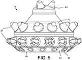
- FIG. 5 illustrates the first roller cone 1 a having the cutter inserts 27 pressed into the sockets 24.
- the pressing may be repeated for each of the remaining sockets 24 of the lands 4b-d.
- stabilizer inserts 32 may be pressed into the respective sockets 24 thereof.
- Each stabilizer insert 32 may be made from a cermet, such as a cemented carbide. The cemented carbide may be cobalt-tungsten carbide.
- Each stabilizer insert 32 may be cylindrical and may have a diameter slightly greater than a diameter of the respective socket 24 to form an interference fit therebetween.
- Each stabilizer insert 32 may be pressed into the respective socket in a similar fashion to that of the cutter inserts 27, discussed above.
- each stabilizer insert 32 may have a diameter slightly less than a diameter of the respective socket 24 and the stabilizer insert may be mounted in the respective socket, such as by brazing, instead of interference fit.
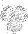
- Figure 6 illustrates a drill bit 33 having the roller cones 1 a-c.
- the drill bit 33 may include a body (not shown) and the roller cones 1 a-c.
- the nose lands 4d and the inner lands 4c of the roller cones 1 a-c may be offset relative each other to form a continuous cutting profile.
- the third roller cone 1 c may further have an outer land 4e formed adjacent to the gage land 4b thereof and in an outer surface thereof.
- the flats 8, sockets 24, and cutter inserts 27 of the outer land 4e may be oversized relative thereto, thereby overlapping with the gage land 4b thereof.
- the body may have an upper shank and a lower leg for each roller cone 1a-c.
- the body may be made from a metal or alloy, such as steel.
- Each leg may be attached to the shank, such as by welding.
- the legs may be equally spaced around the body, such as three at one hundred twenty degrees.
- the shank may have a coupling, such as a threaded pin, formed at an upper end thereof for connection to another member of a bottomhole assembly of a drill string for drilling a wellbore.
- a bore may be formed in the shank and may extend from an upper end thereof to a plenum formed therein adjacent to a lower end thereof.
- Each leg may have an upper shoulder, a mid shirttail, a lower bearing shaft, and a ported boss.
- the shoulder, shirttail, ported boss, and bearing shaft of each leg may be interconnected, such as by being integrally formed and/or welded together.
- Each ported boss may be in fluid communication with the plenum via a respective port formed in the shank and may have a nozzle fastened therein for discharging drilling fluid onto the respective roller cone 1 a-c.
- Each bearing shaft may extend from the respective shirttail in a radially inclined direction.
- Each bearing shaft may have a journal for supporting rotation of the respective roller cone 1a-c therefrom.
- Each leg may have a lubricant reservoir formed therein and a lubricant passage extending from the reservoir to the respective journal bearing formed between the bearing shaft and the respective roller cone 1 a-c.
- the lubricant may be retained within the each leg by a seal, such as an o-ring, positioned in a seal gland between the respective cone 1 a-c and the bearing shaft.
- Each leg may also have a fill port in fluid communication with the lubricant reservoir and closed by a pressure compensator.
- Each roller cone 1 a-c may be mounted to the respective leg by a plurality of balls (not shown) received in a race formed by aligned grooves in each roller cone and the respective bearing shaft.
- the balls may be fed to each race by a ball passage formed in each leg and retained therein by a respective ball plug.
- Each ball plug may be attached to the respective leg, such as by welding.
- Upper and lower edges of each shirttail may be protected from erosion and/or abrasion by respective hardfacing with a ceramic or cermet material.
- An outer surface of each shirttail may also be protected from erosion and/or abrasion by stabilizer inserts secured into sockets thereof, such as by interference fit or brazing.
- each cutter of the inner land 4c and/or nose land 4d of any one or all of the roller cones 1 a-c may be a milled tooth hardfaced by a ceramic or cermet material instead of the cutter insert 27.
- the lubricant system may be omitted from the drill bit 33 and the drill bit may be used in a mining operation instead of a wellbore drilling operation.
- Figure 7 illustrates carburization of a first roller cone 36, according to another embodiment of the present disclosure.
- a promoter 37 may be applied to the first roller cone 36 at all surfaces thereof except for the flats 8.
- the first roller cone 36 may be otherwise identical to the first roller cone 1 a.
- the promoter 37 may be a carbon-rich paint or paste and may be applied using the brush 11 or any alternatives therefor discussed above.
- the first roller cone 36 may be loaded into a furnace 34.
- the furnace 34 may include a housing 35, the heating element 14, the PLC 15, the temperature sensor 16, and the power supply (not shown). Before loading of the first roller cone 36, the furnace 34 may be preheated to a carburizing temperature. The first roller cone 36 may be loaded and allowed to sit in the furnace for the predetermined period of time 23 sufficient for carburization of the promoted portion thereof.
- the first roller cone may be unloaded from the furnace 34 and quenched.
- the first roller cone 36 may then be loaded into a heat treatment furnace (not shown) and tempered therein.
- the sockets may be formed into the first roller cone 36 at the flats 8 and the inserts may be pressed into the sockets as discussed above for the first roller cone 1 a.
- the other two roller cones may be processed in a similar fashion and the three cones mounted to legs of a drill bit as discussed above.
- the spot facing may be omitted and the promoter 37 may be manually applied by covering the first roller cone 1a cone with a template (not shown) to guide application of the promoter between spots (corresponding to the flats 8 but without altering the outer surface of the first roller cone 36) of the lands thereof and to the rest of the surfaces thereof.
- the spot facing may be omitted and the promoter 37 may be applied by a robot (not shown) programmed to apply inhibitor between spots (corresponding to the flats 8 but without altering the outer surface of the first roller cone 36) of the lands thereof and to the rest of the surfaces thereof.
Landscapes
- Engineering & Computer Science (AREA)
- Chemical & Material Sciences (AREA)
- Mechanical Engineering (AREA)
- Life Sciences & Earth Sciences (AREA)
- Geology (AREA)
- Mining & Mineral Resources (AREA)
- Organic Chemistry (AREA)
- Metallurgy (AREA)
- Materials Engineering (AREA)
- Chemical Kinetics & Catalysis (AREA)
- Environmental & Geological Engineering (AREA)
- Geochemistry & Mineralogy (AREA)
- General Life Sciences & Earth Sciences (AREA)
- Fluid Mechanics (AREA)
- Physics & Mathematics (AREA)
- Earth Drilling (AREA)
- Solid-Phase Diffusion Into Metallic Material Surfaces (AREA)
- Gears, Cams (AREA)
Abstract
Description
- The present disclosure generally relates to a roller cone drill bit with improved erosion resistance.
-
U.S. Pat. No. 4,303,137 discloses a method for manufacturing tungsten carbide insert-type cutter cones for a rock bit for drilling oil wells and the like. A cone blank is formed from medium to high carbon steel by forging and machining. The cone blank has a generally conical external surface, a generally cylindrical internal bearing cavity, and a circumferentially extending ball bearing race in the bearing cavity. The cone blank is heat treated by quenching and tempering to a desired core hardness. Insert holes are drilled in the external surface of the heat treated cone blank for insertion of tungsten carbide inserts. The surface of the ball race is selectively hardened by heating and quenching for forming a surface layer having a higher hardness than the core hardness. Selective hardening of the ball race is obtained by applying energy to the surface of the ball race by induction heating, an electron beam or a laser beam to austenitize a surface layer which is rapidly cooled for hardening. -
U.S. Pat. No. 4,708,752 discloses that a medium to high carbon steel body of a roller cone for a drilling bit is machined to final dimensions, and is thereafter rendered absorbent to laser light by application of black paint or black etch. Holes for hard tungsten carbide or like inserts are drilled in the light absorbent steel body. The entire steel body, including the holes, is subjected to a laser treatment which, however, is effective to raise to above austenitizing temperature only the dark light absorbent surfaces. Walls of the insert holes, being shiny, reflect the laser light and are not effected by it. Rapid self-quenching of the laser heated surfaces results in a hard martensitic layer in the external surface, with a surface hardness of 57 to 60 Rockwell C units. The seal gland, heel, and spindle bore areas of the roller cones are hardened similarly by exposure to laser light. In an alternative process, the hard tungsten carbide or like inserts are press fitted into the holes before the laser treatment. The subsequent laser treatment does not affect the inserts adversely, because the inserts, too, have shiny light reflective surfaces, and therefore do not absorb the laser light. -
U.S. Pat. No. 5,975,223 discloses a rock drill bit for rotary crushing machining of rock. The rock drill bit includes legs, each of which carry a journal provided with bearing surfaces cooperating via bearing elements with bearing races in a rotatable roller provided with inserts or chisels. Each leg is made from a parent material with substantially homogeneous hardness and each leg comprises a leg tail provided to resist entrance of drill cuttings into the bearings. The bearing surfaces have higher wear resistance than the parent material and the leg tail is at least partly of the same material condition as the bearing surfaces. The invention further relates to a method of manufacturing a rock drill bit. -
U.S. Pat. No. 7,210,377 discloses a method of forming a drill bit structure, the method including fixing spacers to the drill bit structure. The spacers are arranged at preselected locations on an outer surface of the drill bit structure. A hardfacing material is then applied to the drill bit structure, and the spacers are removed. Holes are machined in the drill bit structure at the preselected locations, and drilling inserts are positioned in each hole. A method of forming a drill bit structure, the method including applying a hardfacing material to selected surfaces of the drill bit structure. The hardfacing material includes a perforated carbide infiltrated material and a perforated powder infiltrated material. The perforations in the powder infiltrated material correspond to the perforations in the carbide infiltrated material. Holes are machined in the drill bit structure at the locations of the perforations, and drilling inserts are positioned in each hole. -
U.S. Pat. No. 8,307,920 discloses an earth boring drill bit that includes a cutting cone with a cutting disk. Compacts are inserted within the disk having a chisel shaped end set flush with the cutting disk periphery. The compact crests and cutting disk periphery form a generally seamless cutting surface. The cutting cone can further include cutting teeth thereon also having flush mounted compacts. The compacts can be made from a material such as cemented carbide, hardfacing, tungsten, tungsten alloys, tungsten carbide and the cutter made from steel. - The present disclosure generally relates to a roller cone drill bit with improved erosion resistance. In a first embodiment, a method of manufacturing a roller cone for a drill bit includes: selectively carburizing a land of the roller cone between a plurality of spots on the land for protection against erosion; after carburization, forming sockets in the roller cone at the spots; and mounting cermet inserts in the sockets.
- In one aspect of the first embodiment, the spots are circular. In a sub-aspect, the circular spots are slightly oversized relative to the sockets to prevent leakage of the carburization therein, such as a diameter of each spot being ten to sixty percent greater than a diameter of the respective socket.
- So that the manner in which the above recited features of the present disclosure can be understood in detail, a more particular description of the disclosure, briefly summarized above, may be had by reference to embodiments, some of which are illustrated in the appended drawings. It is to be noted, however, that the appended drawings illustrate only typical embodiments of this disclosure and are therefore not to be considered limiting of its scope, for the disclosure may admit to other equally effective embodiments.
-
Figures 1A-1D illustrate spot facing of a first roller cone, according to one embodiment of the present disclosure. -
Figure 2A illustrates the first roller cone having flats produced by the spot facing.Figure 2B illustrates applying inhibitor to one of the flats.Figure 2C illustrates the first roller cone having the inhibitor applied to the flats. -
Figure 3A illustrates carburizing of the first roller cone.Figures 3B and 3C illustrate forming a socket at one of the flats. -
Figure 4A illustrates a second roller cone having the sockets formed therein at the flats.Figure 4B illustrates pressing a cutter insert into one of the sockets. -
Figure 5 illustrates the first roller cone having the cutter inserts pressed into the sockets. -
Figure 6 illustrates a drill bit having the roller cones. -
Figure 7 illustrates carburization of a first roller cone, according to another embodiment of the present disclosure. -
Figures 1A-1D illustrate spot facing of afirst roller cone 1a, according to one embodiment of the present disclosure. Thefirst roller cone 1 a may start from a forged steel body of a conical shape. Ahandling socket 2 may be formed into a rear of the steel body for mounting thereof onto aspindle 3 of a machine tool, such as a lathe. The lathe may be manually operated or CNC. One or more lands, such as aheel land 4a, agage land 4b, aninner land 4c, and anose land 4d may be formed in an outer surface of the body, such as by turning, using the lathe. - Once the
lands 4a-d have been formed, thespindle 3 may be locked and aspot facer 5 may be spun 6 and plunged 7p into an outer surface of one of the lands, such as thegage land 4b, until a flat 8 is formed. Thespot facer 5 may be a counterbore bit (shown) or an end mill (not shown) and, if an end mill, may be articulated to form the flat 8 after plunging 7p. Thespot facer 5 may be plunged 7p manually or be plunged and articulated by the CNC machine. Once the flat 8 has been formed, thespot facer 5 may be raised 7r and thespindle 3 may be unlocked and rotated 9 by a predetermined increment. Once rotated by the increment, thespindle 3 may be relocked and thespot facer 5 used to form a second flat. The spot facing process may be repeated until a set of flats has been formed around the selectedland 4b. - Although implied that the
spot facer 5 is in a vertical orientation, the spot facer may be in a horizontal orientation instead. -
Figure 2A illustrates thefirst roller cone 1 a havingflats 8 produced by the spot facing. Once the selectedland 4b has been spot faced, the spot facing process may be repeated for theother lands 4a,c,d. Each flat 8 may be circular and may correspond to a location where an insert may later be mounted. Once theflats 8 have been formed, the handlingsocket 2 may be enlarged, such as by machining, to form a bearing shaft receptacle (not shown) for mounting thefirst roller cone 1 a to a leg (not shown) of a drill bit. -
Figure 2B illustrates applyinginhibitor 10 to one of theflats 8. Once the bearing shaft receptacle has been formed, theinhibitor 10 may be applied to one of theflats 8 for protection of a region of thefirst roller cone 1 a adjacent to the flat from carburization. Theinhibitor 10 may be metallic paint or paste and may be applied using abrush 11. The inhibitor paint or paste may be formulated with a base metal having little or no affinity for carbon, such as copper. Theinhibitor 10 may be applied manually or the application may be automated, such as by a robot. - Advantageously, for manual application of the
inhibitor 10, theflats 8 provide a clear visual guide. - Alternatively, the
inhibitor 10 may be applied using a sprayer, such as an airbrush (shown) or a spray gun (not shown). Alternatively, the spot facing may be omitted and theinhibitor 10 may be manually applied by covering thefirst roller cone 1 a cone with a template (not shown) having holes formed therein to guide application of the inhibitor onto spots (corresponding to theflats 8 but without altering the outer surface of thefirst roller cone 1 a) of thelands 4a-d thereof. Alternatively, the spot facing may be omitted and theinhibitor 10 may be applied by a robot (not shown) programmed to apply inhibitor onto spots (corresponding to theflats 8 but without altering the outer surface of thefirst roller cone 1 a) of thelands 4a-d thereof. -
Figure 2C illustrates thefirst roller cone 1 a having theinhibitor 10 applied to theflats 8. The application of theinhibitor 10 may then be repeated for the rest of theflats 8 of theroller cone 1 a. -
Figure 3A illustrates carburizing of thefirst roller cone 1 a. Once theinhibitor 10 has been applied to all of theflats 8 and has been allowed to cure, thefirst roller cone 1 a may be loaded into acarburization furnace 12. Thecarburization furnace 12 may include ahousing 13, aheating element 14, a controller, such as programmable logic controller (PLC) 15, atemperature sensor 16, acarbon potential sensor 17, areactor 18, and a power supply (not shown). - The
reactor 18 may be mounted to a sidewall of thehousing 13 and extend through an opening therein. Thereactor 18 may include a plurality of concentric tubes, such as afeed tube 18f, acombustion tube 18c, aheater tube 18h, and agenerator tube 18g. Thereactor 18 may further include a manifold 18m having a first inlet in fluid communication with thefeed tube 18f for supplyingfuel 19 thereto. Thereactor 18 may further include adiffuser 18d connected to a distal end of thefeed tube 18f and an igniter (not shown) disposed within thecombustion tube 18c adjacent to the diffuser. The manifold 18m may further have a second inlet in fluid communication with thecombustion tube 18c for supplying an oxidizer, such asair 20, thereto. Theair 20 may flow down an annulus formed between thefeed tube 18f and thecombustion tube 18c to thediffuser 18d for mixing with thefuel 19. An end of thecombustion tube 18c may be closed for divertingexhaust 21 resulting from combustion of thefuel 19 andair 20 up an annulus formed between thecombustion tube 18c and theheater tube 18h to an outlet of the manifold 18m. The manifold 18m may also have a baffle isolating the outlet from the second inlet. - The manifold 18m may further have a third inlet in fluid communication with the
generator tube 18g for supplying amixture 22 of air and enriching gas thereto. The enriching gas may be a hydrocarbon or carbon-oxide. Themixture 22 may flow down an annulus formed between thegenerator tube 18g and theheater tube 18h for being heated by thecounter-flowing exhaust 21 and/or radiation from the combustion. Thereactor 18 may further includecatalyst 18y packed along a portion of the annulus formed between thegenerator tube 18g and theheater tube 18h to promote cracking of themixture 22. Thecatalyst 18y may be metallic, such as electrolytic nickel. The cracked mixture (not shown) may be discharged from the generator tube into a chamber formed in thehousing 13 to establish a carburizing atmosphere therein. - Before loading of the
first roller cone 1 a, thefurnace 12 may be preheated to a carburizing temperature and thereactor 18 operated to establish the carburizing atmosphere. Thefirst roller cone 1 a may be loaded and allowed to sit in the furnace for a predetermined period oftime 23 sufficient for carburization of an uninhibited portion thereof. Theinhibitor 10 may protect theflats 8 from carburization thereof. - Once carburization of the
first roller cone 1 a is complete, the first roller cone may be unloaded from thecarburization furnace 12 and quenched. Thefirst roller cone 1 a may then be loaded into a heat treatment furnace (not shown) and tempered therein. - Alternatively, the
reactor 18 may be omitted and thefirst roller cone 1 a may instead be packed with carburizing material. Alternatively, thereactor 18 may be a separate unit from thefurnace 12 and the cracked mixture may be piped thereto. -
Figures 3B and 3C illustrate forming asocket 24 at one of theflats 8. Once thefirst roller cone 1 a has been quenched and tempered, adrill bit 25d may be spun 6 and plunged 7p into the flat 8 to form apilot hole 26 in thefirst roller cone 1 a. Once thepilot hole 26 has been formed, areamer 25r may be spun 6 and plunged 7p into thepilot hole 26 to form thesocket 24 in thefirst roller cone 1a. Once thesocket 24 has been formed into the flat 8, the drilling and reaming process may be repeated for the rest of theflats 8 to form thesockets 24 in thefirst roller cone 1 a. Each flat 8 may be slightly oversized relative to therespective socket 24 to prevent leakage of carburization into therespective socket 24. A diameter of each flat 8 may be greater than a diameter of therespective socket 24, such as ten to sixty percent greater, to prevent the leakage. The oversizing may be limited such that the remainders of thelands 4a-d are still adequately protected from abrasion and/or erosion by the carburization. -
Figure 4A illustrates asecond roller 1 b cone having thesockets 24 formed therein at theflats 8. As the spot facing, applyinginhibitor 10, carburizing, and socket forming processes are being performed on thefirst roller cone 1a, the processes may be contemporaneously or immediately thereafter performed on second 1 b and third 1 c (Figure 6 ) roller cones. -
Figure 4B illustrates pressing acutter insert 27 into one of thesockets 24. Eachcutter insert 27 may be made from a cermet, such as a cemented carbide. The cemented carbide may be cobalt-tungsten carbide. Eachcutter insert 27 may have a cylindrical base and a nose extending from the base. Each nose may be dome-shaped, conical, or chisel-shaped, such as eachcutter insert 27 of the gage lands 4b having a chisel-shaped nose and each cutter insert of the inner 4c andnose 4d lands having a conical nose. Each base may have a diameter slightly greater than a diameter of therespective socket 24 to form an interference fit therebetween. To mount eachcutter insert 27 into therespective socket 24, asleeve 28 may be fit onto the nose of the respective cutter insert. The base of therespective cutter insert 27 may be aligned with the respective socket and amallet 29 may be swung 30 to tap thesleeve 28, thereby pressing 31 thecutter insert 27 into therespective socket 24. - Alternatively, the base of each
cutter insert 27 may have a diameter slightly less than a diameter of therespective socket 24 and the cutter insert may be mounted in the respective socket, such as by brazing, instead of interference fit. -
Figure 5 illustrates thefirst roller cone 1 a having the cutter inserts 27 pressed into thesockets 24. Once thecutter insert 27 has been pressed into therespective socket 24, the pressing may be repeated for each of the remainingsockets 24 of thelands 4b-d. For theheel land 4a, stabilizer inserts 32 may be pressed into therespective sockets 24 thereof. Eachstabilizer insert 32 may be made from a cermet, such as a cemented carbide. The cemented carbide may be cobalt-tungsten carbide. Eachstabilizer insert 32 may be cylindrical and may have a diameter slightly greater than a diameter of therespective socket 24 to form an interference fit therebetween. Eachstabilizer insert 32 may be pressed into the respective socket in a similar fashion to that of the cutter inserts 27, discussed above. - Alternatively, the base of each
stabilizer insert 32 may have a diameter slightly less than a diameter of therespective socket 24 and the stabilizer insert may be mounted in the respective socket, such as by brazing, instead of interference fit. -
Figure 6 illustrates a drill bit 33 having the roller cones 1 a-c. The drill bit 33 may include a body (not shown) and the roller cones 1 a-c. The nose lands 4d and theinner lands 4c of the roller cones 1 a-c may be offset relative each other to form a continuous cutting profile. Thethird roller cone 1 c may further have anouter land 4e formed adjacent to thegage land 4b thereof and in an outer surface thereof. Theflats 8,sockets 24, and cutter inserts 27 of theouter land 4e may be oversized relative thereto, thereby overlapping with thegage land 4b thereof. - The body may have an upper shank and a lower leg for each
roller cone 1a-c. The body may be made from a metal or alloy, such as steel. Each leg may be attached to the shank, such as by welding. The legs may be equally spaced around the body, such as three at one hundred twenty degrees. The shank may have a coupling, such as a threaded pin, formed at an upper end thereof for connection to another member of a bottomhole assembly of a drill string for drilling a wellbore. A bore may be formed in the shank and may extend from an upper end thereof to a plenum formed therein adjacent to a lower end thereof. - Each leg may have an upper shoulder, a mid shirttail, a lower bearing shaft, and a ported boss. The shoulder, shirttail, ported boss, and bearing shaft of each leg may be interconnected, such as by being integrally formed and/or welded together. Each ported boss may be in fluid communication with the plenum via a respective port formed in the shank and may have a nozzle fastened therein for discharging drilling fluid onto the respective roller cone 1 a-c. Each bearing shaft may extend from the respective shirttail in a radially inclined direction. Each bearing shaft may have a journal for supporting rotation of the
respective roller cone 1a-c therefrom. Each leg may have a lubricant reservoir formed therein and a lubricant passage extending from the reservoir to the respective journal bearing formed between the bearing shaft and the respective roller cone 1 a-c. The lubricant may be retained within the each leg by a seal, such as an o-ring, positioned in a seal gland between the respective cone 1 a-c and the bearing shaft. Each leg may also have a fill port in fluid communication with the lubricant reservoir and closed by a pressure compensator. - Each roller cone 1 a-c may be mounted to the respective leg by a plurality of balls (not shown) received in a race formed by aligned grooves in each roller cone and the respective bearing shaft. The balls may be fed to each race by a ball passage formed in each leg and retained therein by a respective ball plug. Each ball plug may be attached to the respective leg, such as by welding. Upper and lower edges of each shirttail may be protected from erosion and/or abrasion by respective hardfacing with a ceramic or cermet material. An outer surface of each shirttail may also be protected from erosion and/or abrasion by stabilizer inserts secured into sockets thereof, such as by interference fit or brazing.
- Alternatively, each cutter of the
inner land 4c and/ornose land 4d of any one or all of the roller cones 1 a-c may be a milled tooth hardfaced by a ceramic or cermet material instead of thecutter insert 27. Alternatively, the lubricant system may be omitted from the drill bit 33 and the drill bit may be used in a mining operation instead of a wellbore drilling operation. -
Figure 7 illustrates carburization of afirst roller cone 36, according to another embodiment of the present disclosure. Instead of using theinhibitor 10 to selectively carburize thefirst roller cone 1 a, apromoter 37 may be applied to thefirst roller cone 36 at all surfaces thereof except for theflats 8. Thefirst roller cone 36 may be otherwise identical to thefirst roller cone 1 a. Thepromoter 37 may be a carbon-rich paint or paste and may be applied using thebrush 11 or any alternatives therefor discussed above. - Once the
promoter 37 has been applied and has been allowed to cure, thefirst roller cone 36 may be loaded into afurnace 34. Thefurnace 34 may include ahousing 35, theheating element 14, thePLC 15, thetemperature sensor 16, and the power supply (not shown). Before loading of thefirst roller cone 36, thefurnace 34 may be preheated to a carburizing temperature. Thefirst roller cone 36 may be loaded and allowed to sit in the furnace for the predetermined period oftime 23 sufficient for carburization of the promoted portion thereof. - Once carburization of the
first roller cone 36 is complete, the first roller cone may be unloaded from thefurnace 34 and quenched. Thefirst roller cone 36 may then be loaded into a heat treatment furnace (not shown) and tempered therein. Once heat treatment has been completed, the sockets may be formed into thefirst roller cone 36 at theflats 8 and the inserts may be pressed into the sockets as discussed above for thefirst roller cone 1 a. The other two roller cones may be processed in a similar fashion and the three cones mounted to legs of a drill bit as discussed above. - Alternatively, the spot facing may be omitted and the
promoter 37 may be manually applied by covering thefirst roller cone 1a cone with a template (not shown) to guide application of the promoter between spots (corresponding to theflats 8 but without altering the outer surface of the first roller cone 36) of the lands thereof and to the rest of the surfaces thereof. Alternatively, the spot facing may be omitted and thepromoter 37 may be applied by a robot (not shown) programmed to apply inhibitor between spots (corresponding to theflats 8 but without altering the outer surface of the first roller cone 36) of the lands thereof and to the rest of the surfaces thereof. - While the foregoing is directed to embodiments of the present disclosure, other and further embodiments of the disclosure may be devised without departing from the basic scope thereof, and the scope of the invention is determined by the claims that follow.
Claims (15)
- A method of manufacturing a roller cone for a drill bit, comprising:selectively carburizing a land of the roller cone between a plurality of spots on the land for protection against erosion;after carburization, forming sockets in the roller cone at the spots; andmounting cermet inserts in the sockets.
- The method of claim 1, wherein the land is selectively carburized by:applying inhibitor to each spot; andcarburizing the roller cone,wherein the inhibitor prevents carburization of the spots while the remainder of the land is carburized.
- The method of claim 2, wherein the inhibitor is a metallic paint or paste.
- The method of claim 3, wherein the inhibitor is copper-based.
- The method of claim 2, further comprising spot facing a plurality of flats in the land at the spots, wherein the inhibitor is applied to the flats.
- The method of any preceding claim, wherein the land is selectively carburized by:applying carbon-rich paint or paste to the land between the spots, andheating the roller cone.
- The method of any preceding claim, wherein:the land is a gage land, andthe inserts are cutter inserts.
- The method of claim 7, wherein:a heel land of the roller cone is also selectively carburized, andthe method further comprises repeating the socket forming and insert mounting for the heel land.
- The method of claim 8, wherein:inner and nose lands of the roller cone are also selectively carburized, andthe method further comprises repeating the socket forming and insert mounting for the inner and nose lands.
- The method of claim 7, wherein:an outer land of the roller cone is also selectively carburized, andthe method further comprises repeating the socket forming and insert mounting for the outer land.
- The method of any preceding claim, wherein:the land is a heel land, andthe inserts are stabilizer inserts.
- The method of any preceding claim, wherein the spots are circular.
- The method of any preceding claim, wherein the inserts are mounted in the sockets by press fitting.
- The method of any preceding claim, wherein the sockets are each formed by drilling a pilot hole and then reaming the pilot hole into the respective socket.
- A drill bit, comprising:a body having a shank for connection to a drill string and a plurality of legs attached to the shank; anda plurality of roller cones, each roller cone mounted to a respective leg and manufactured according to the method of any preceding claim.
Applications Claiming Priority (1)
| Application Number | Priority Date | Filing Date | Title |
|---|---|---|---|
| US15/151,552 US9988854B2 (en) | 2016-05-11 | 2016-05-11 | Roller cone drill bit with improved erosion resistance |
Publications (2)
| Publication Number | Publication Date |
|---|---|
| EP3243926A1 true EP3243926A1 (en) | 2017-11-15 |
| EP3243926B1 EP3243926B1 (en) | 2020-07-22 |
Family
ID=58709248
Family Applications (1)
| Application Number | Title | Priority Date | Filing Date |
|---|---|---|---|
| EP17170319.2A Active EP3243926B1 (en) | 2016-05-11 | 2017-05-10 | Method of manufacturing a roller cone drill bit with improved erosion resistance |
Country Status (4)
| Country | Link |
|---|---|
| US (1) | US9988854B2 (en) |
| EP (1) | EP3243926B1 (en) |
| CN (1) | CN107447183B (en) |
| RU (1) | RU2724680C2 (en) |
Families Citing this family (2)
| Publication number | Priority date | Publication date | Assignee | Title |
|---|---|---|---|---|
| CA3141096A1 (en) * | 2020-12-03 | 2022-06-03 | Taurex Drill Bits, LLC | Manufacture of roller cone drill bits |
| CN114562212A (en) * | 2022-02-25 | 2022-05-31 | 中石化江钻石油机械有限公司 | Method for manufacturing shell abrasion-proof roller cone and roller cone bit |
Citations (6)
| Publication number | Priority date | Publication date | Assignee | Title |
|---|---|---|---|---|
| US4303137A (en) | 1979-09-21 | 1981-12-01 | Smith International, Inc. | Method for making a cone for a rock bit and product |
| US4708752A (en) | 1986-03-24 | 1987-11-24 | Smith International, Inc. | Process for laser hardening drilling bit cones having hard cutter inserts placed therein |
| US4756373A (en) * | 1986-12-23 | 1988-07-12 | Trw Inc. | Rock drilling bit and a method of producing the same |
| US5975223A (en) | 1995-03-13 | 1999-11-02 | Sandvik Ab | Rock drill bit and method for hardening a rock drill bit |
| US7210377B2 (en) | 2001-10-10 | 2007-05-01 | Smith International, Inc. | Cone erosion protection for roller cone drill bits |
| US8307920B2 (en) | 2009-08-13 | 2012-11-13 | Baker Hughes Incorporated | Roller cone disk with shaped compacts |
Family Cites Families (19)
| Publication number | Priority date | Publication date | Assignee | Title |
|---|---|---|---|---|
| US1480418A (en) | 1922-03-25 | 1924-01-08 | Houghton & Co E F | Material for carburizing |
| SU108521A1 (en) * | 1956-09-23 | 1956-11-30 | Д.К. Киселев | Drill bit sharoshka |
| US3842921A (en) | 1973-08-10 | 1974-10-22 | Hughes Tool Co | Boronized drill bit cutters |
| US3946817A (en) | 1974-12-23 | 1976-03-30 | Hughes Tool Company | Differentially carburized rock bit cutter |
| JPS58151407A (en) * | 1982-03-03 | 1983-09-08 | Kawasaki Steel Corp | Bit for spot facing for tap hole of blast furnace |
| US4907665A (en) | 1984-09-27 | 1990-03-13 | Smith International, Inc. | Cast steel rock bit cutter cones having metallurgically bonded cutter inserts |
| US4781770A (en) * | 1986-03-24 | 1988-11-01 | Smith International, Inc. | Process for laser hardfacing drill bit cones having hard cutter inserts |
| US4660444A (en) | 1986-06-09 | 1987-04-28 | Dresser Industries, Inc. | Hardening of selected areas of an earth boring rockbit |
| CN2187508Y (en) * | 1994-03-23 | 1995-01-18 | 北京第一机床厂 | Combined drill cutter |
| ZA99430B (en) | 1998-01-23 | 1999-07-21 | Smith International | Hardfacing rock bit cones for erosion protection. |
| US6206115B1 (en) * | 1998-08-21 | 2001-03-27 | Baker Hughes Incorporated | Steel tooth bit with extra-thick hardfacing |
| US6159306A (en) | 1998-10-26 | 2000-12-12 | Barbour; George E. | Carburizing device and method of using the same |
| US7690442B2 (en) * | 2005-05-17 | 2010-04-06 | Smith International, Inc. | Drill bit and cutting inserts for hard/abrasive formations |
| US8261841B2 (en) * | 2009-02-17 | 2012-09-11 | Exxonmobil Research And Engineering Company | Coated oil and gas well production devices |
| US7836792B2 (en) * | 2008-09-25 | 2010-11-23 | Baker Hughes Incorporated | System, method and apparatus for enhanced cutting element retention and support in a rock bit |
| US9624730B2 (en) | 2010-12-01 | 2017-04-18 | Vermeer Manufacturing Company | Hard facing configuration for a drilling tool |
| EA027355B1 (en) * | 2011-02-10 | 2017-07-31 | Смит Интернэшнл, Инк. | Kerfing hybrid drill bit |
| CN104131784A (en) * | 2014-06-30 | 2014-11-05 | 成都高普石油工程技术有限公司 | Drill bit cone processing process |
| CN104195311B (en) * | 2014-09-03 | 2016-06-29 | 湖北鸣利来冶金机械股份有限公司 | Cone bit cone Technology for Heating Processing |
-
2016
- 2016-05-11 US US15/151,552 patent/US9988854B2/en active Active
-
2017
- 2017-05-04 CN CN201710307542.7A patent/CN107447183B/en active Active
- 2017-05-10 EP EP17170319.2A patent/EP3243926B1/en active Active
- 2017-05-10 RU RU2017116163A patent/RU2724680C2/en active
Patent Citations (6)
| Publication number | Priority date | Publication date | Assignee | Title |
|---|---|---|---|---|
| US4303137A (en) | 1979-09-21 | 1981-12-01 | Smith International, Inc. | Method for making a cone for a rock bit and product |
| US4708752A (en) | 1986-03-24 | 1987-11-24 | Smith International, Inc. | Process for laser hardening drilling bit cones having hard cutter inserts placed therein |
| US4756373A (en) * | 1986-12-23 | 1988-07-12 | Trw Inc. | Rock drilling bit and a method of producing the same |
| US5975223A (en) | 1995-03-13 | 1999-11-02 | Sandvik Ab | Rock drill bit and method for hardening a rock drill bit |
| US7210377B2 (en) | 2001-10-10 | 2007-05-01 | Smith International, Inc. | Cone erosion protection for roller cone drill bits |
| US8307920B2 (en) | 2009-08-13 | 2012-11-13 | Baker Hughes Incorporated | Roller cone disk with shaped compacts |
Non-Patent Citations (1)
| Title |
|---|
| SITI K A ET AL: "Mechanical Properties of Paste Carburized ASTM A516 Steel", PROCEDIA ENGINEERING - INTERNATIONAL TRIBOLOGY CONFERENCE MALAYSIA 2013, 18 - 20 NOVEMBER 2013, KOTA KINABALU [MY], vol. 68, 18 November 2013 (2013-11-18), Elsevier B.V. [NL], pages 525 - 530, XP028847525, ISSN: 1877-7058, DOI: 10.1016/J.PROENG.2013.12.216 * |
Also Published As
| Publication number | Publication date |
|---|---|
| US9988854B2 (en) | 2018-06-05 |
| EP3243926B1 (en) | 2020-07-22 |
| RU2017116163A (en) | 2018-11-13 |
| US20170328135A1 (en) | 2017-11-16 |
| CN107447183A (en) | 2017-12-08 |
| CN107447183B (en) | 2021-06-15 |
| RU2017116163A3 (en) | 2020-05-25 |
| RU2724680C2 (en) | 2020-06-25 |
Similar Documents
| Publication | Publication Date | Title |
|---|---|---|
| US4781770A (en) | Process for laser hardfacing drill bit cones having hard cutter inserts | |
| US4679640A (en) | Method for case hardening rock bits and rock bits formed thereby | |
| AU738915B2 (en) | Hardfacing rock bit cones for erosion protection | |
| US4708752A (en) | Process for laser hardening drilling bit cones having hard cutter inserts placed therein | |
| US5038640A (en) | Titanium carbide modified hardfacing for use on bearing surfaces of earth boring bits | |
| US7100712B2 (en) | Method for hardfacing roller cone drill bit legs | |
| US20140034394A1 (en) | Ball hole welding using the friction stir welding (fsw) process | |
| US7210377B2 (en) | Cone erosion protection for roller cone drill bits | |
| EP3243926B1 (en) | Method of manufacturing a roller cone drill bit with improved erosion resistance | |
| US4187743A (en) | Rock bit and method of manufacture | |
| US8240403B2 (en) | Earth-boring tools with improved retention of cutting elements installed within pockets | |
| US4127043A (en) | Rock bit with welded bearing pins | |
| US12352108B2 (en) | Devices, systems, and methods for a bit including a matrix portion and a steel portion | |
| US20010015290A1 (en) | Hardfacing rock bit cones for erosion protection | |
| US6374704B1 (en) | Steel-tooth bit with improved toughness | |
| CA2477644C (en) | Apparatus and method for selective laser-applied cladding | |
| WO2001042615A2 (en) | Drill rod | |
| US4756373A (en) | Rock drilling bit and a method of producing the same | |
| CN112795730B (en) | Heat treatment method for improving performance of drilling tool for down-the-hole drill | |
| US7469618B2 (en) | Maintaining carburized case during neutral to the core heat treatment processes | |
| RU2288339C2 (en) | Method for reinforcing pivot shafts of drilling rolling cutter bit legs | |
| WO2020086194A1 (en) | Hybrid roller cone-mill completions bit | |
| RU2280145C1 (en) | Production method for insert cutter structure of drilling bits | |
| RU2275440C1 (en) | Method of reinforcement of the outer surface of the rolling cutters of the drilling bits with the milled tooling | |
| MX2008006414A (en) | Hardfacing materials with highly conforming properties |
Legal Events
| Date | Code | Title | Description |
|---|---|---|---|
| PUAI | Public reference made under article 153(3) epc to a published international application that has entered the european phase |
Free format text: ORIGINAL CODE: 0009012 |
|
| STAA | Information on the status of an ep patent application or granted ep patent |
Free format text: STATUS: THE APPLICATION HAS BEEN PUBLISHED |
|
| AK | Designated contracting states |
Kind code of ref document: A1 Designated state(s): AL AT BE BG CH CY CZ DE DK EE ES FI FR GB GR HR HU IE IS IT LI LT LU LV MC MK MT NL NO PL PT RO RS SE SI SK SM TR |
|
| AX | Request for extension of the european patent |
Extension state: BA ME |
|
| STAA | Information on the status of an ep patent application or granted ep patent |
Free format text: STATUS: REQUEST FOR EXAMINATION WAS MADE |
|
| 17P | Request for examination filed |
Effective date: 20180515 |
|
| RBV | Designated contracting states (corrected) |
Designated state(s): AL AT BE BG CH CY CZ DE DK EE ES FI FR GB GR HR HU IE IS IT LI LT LU LV MC MK MT NL NO PL PT RO RS SE SI SK SM TR |
|
| STAA | Information on the status of an ep patent application or granted ep patent |
Free format text: STATUS: EXAMINATION IS IN PROGRESS |
|
| 17Q | First examination report despatched |
Effective date: 20190412 |
|
| GRAP | Despatch of communication of intention to grant a patent |
Free format text: ORIGINAL CODE: EPIDOSNIGR1 |
|
| STAA | Information on the status of an ep patent application or granted ep patent |
Free format text: STATUS: GRANT OF PATENT IS INTENDED |
|
| INTG | Intention to grant announced |
Effective date: 20200205 |
|
| GRAS | Grant fee paid |
Free format text: ORIGINAL CODE: EPIDOSNIGR3 |
|
| GRAA | (expected) grant |
Free format text: ORIGINAL CODE: 0009210 |
|
| STAA | Information on the status of an ep patent application or granted ep patent |
Free format text: STATUS: THE PATENT HAS BEEN GRANTED |
|
| AK | Designated contracting states |
Kind code of ref document: B1 Designated state(s): AL AT BE BG CH CY CZ DE DK EE ES FI FR GB GR HR HU IE IS IT LI LT LU LV MC MK MT NL NO PL PT RO RS SE SI SK SM TR |
|
| REG | Reference to a national code |
Ref country code: GB Ref legal event code: FG4D |
|
| REG | Reference to a national code |
Ref country code: CH Ref legal event code: EP |
|
| REG | Reference to a national code |
Ref country code: DE Ref legal event code: R096 Ref document number: 602017020046 Country of ref document: DE |
|
| REG | Reference to a national code |
Ref country code: AT Ref legal event code: REF Ref document number: 1293455 Country of ref document: AT Kind code of ref document: T Effective date: 20200815 |
|
| REG | Reference to a national code |
Ref country code: IE Ref legal event code: FG4D |
|
| REG | Reference to a national code |
Ref country code: SE Ref legal event code: TRGR |
|
| REG | Reference to a national code |
Ref country code: LT Ref legal event code: MG4D |
|
| REG | Reference to a national code |
Ref country code: AT Ref legal event code: MK05 Ref document number: 1293455 Country of ref document: AT Kind code of ref document: T Effective date: 20200722 |
|
| PG25 | Lapsed in a contracting state [announced via postgrant information from national office to epo] |
Ref country code: ES Free format text: LAPSE BECAUSE OF FAILURE TO SUBMIT A TRANSLATION OF THE DESCRIPTION OR TO PAY THE FEE WITHIN THE PRESCRIBED TIME-LIMIT Effective date: 20200722 Ref country code: AT Free format text: LAPSE BECAUSE OF FAILURE TO SUBMIT A TRANSLATION OF THE DESCRIPTION OR TO PAY THE FEE WITHIN THE PRESCRIBED TIME-LIMIT Effective date: 20200722 Ref country code: HR Free format text: LAPSE BECAUSE OF FAILURE TO SUBMIT A TRANSLATION OF THE DESCRIPTION OR TO PAY THE FEE WITHIN THE PRESCRIBED TIME-LIMIT Effective date: 20200722 Ref country code: LT Free format text: LAPSE BECAUSE OF FAILURE TO SUBMIT A TRANSLATION OF THE DESCRIPTION OR TO PAY THE FEE WITHIN THE PRESCRIBED TIME-LIMIT Effective date: 20200722 Ref country code: PT Free format text: LAPSE BECAUSE OF FAILURE TO SUBMIT A TRANSLATION OF THE DESCRIPTION OR TO PAY THE FEE WITHIN THE PRESCRIBED TIME-LIMIT Effective date: 20201123 Ref country code: BG Free format text: LAPSE BECAUSE OF FAILURE TO SUBMIT A TRANSLATION OF THE DESCRIPTION OR TO PAY THE FEE WITHIN THE PRESCRIBED TIME-LIMIT Effective date: 20201022 Ref country code: FI Free format text: LAPSE BECAUSE OF FAILURE TO SUBMIT A TRANSLATION OF THE DESCRIPTION OR TO PAY THE FEE WITHIN THE PRESCRIBED TIME-LIMIT Effective date: 20200722 Ref country code: GR Free format text: LAPSE BECAUSE OF FAILURE TO SUBMIT A TRANSLATION OF THE DESCRIPTION OR TO PAY THE FEE WITHIN THE PRESCRIBED TIME-LIMIT Effective date: 20201023 Ref country code: NO Free format text: LAPSE BECAUSE OF FAILURE TO SUBMIT A TRANSLATION OF THE DESCRIPTION OR TO PAY THE FEE WITHIN THE PRESCRIBED TIME-LIMIT Effective date: 20201022 |
|
| PG25 | Lapsed in a contracting state [announced via postgrant information from national office to epo] |
Ref country code: LV Free format text: LAPSE BECAUSE OF FAILURE TO SUBMIT A TRANSLATION OF THE DESCRIPTION OR TO PAY THE FEE WITHIN THE PRESCRIBED TIME-LIMIT Effective date: 20200722 Ref country code: RS Free format text: LAPSE BECAUSE OF FAILURE TO SUBMIT A TRANSLATION OF THE DESCRIPTION OR TO PAY THE FEE WITHIN THE PRESCRIBED TIME-LIMIT Effective date: 20200722 Ref country code: PL Free format text: LAPSE BECAUSE OF FAILURE TO SUBMIT A TRANSLATION OF THE DESCRIPTION OR TO PAY THE FEE WITHIN THE PRESCRIBED TIME-LIMIT Effective date: 20200722 Ref country code: IS Free format text: LAPSE BECAUSE OF FAILURE TO SUBMIT A TRANSLATION OF THE DESCRIPTION OR TO PAY THE FEE WITHIN THE PRESCRIBED TIME-LIMIT Effective date: 20201122 |
|
| PG25 | Lapsed in a contracting state [announced via postgrant information from national office to epo] |
Ref country code: NL Free format text: LAPSE BECAUSE OF FAILURE TO SUBMIT A TRANSLATION OF THE DESCRIPTION OR TO PAY THE FEE WITHIN THE PRESCRIBED TIME-LIMIT Effective date: 20200722 |
|
| REG | Reference to a national code |
Ref country code: DE Ref legal event code: R097 Ref document number: 602017020046 Country of ref document: DE |
|
| PG25 | Lapsed in a contracting state [announced via postgrant information from national office to epo] |
Ref country code: RO Free format text: LAPSE BECAUSE OF FAILURE TO SUBMIT A TRANSLATION OF THE DESCRIPTION OR TO PAY THE FEE WITHIN THE PRESCRIBED TIME-LIMIT Effective date: 20200722 Ref country code: CZ Free format text: LAPSE BECAUSE OF FAILURE TO SUBMIT A TRANSLATION OF THE DESCRIPTION OR TO PAY THE FEE WITHIN THE PRESCRIBED TIME-LIMIT Effective date: 20200722 Ref country code: DK Free format text: LAPSE BECAUSE OF FAILURE TO SUBMIT A TRANSLATION OF THE DESCRIPTION OR TO PAY THE FEE WITHIN THE PRESCRIBED TIME-LIMIT Effective date: 20200722 Ref country code: SM Free format text: LAPSE BECAUSE OF FAILURE TO SUBMIT A TRANSLATION OF THE DESCRIPTION OR TO PAY THE FEE WITHIN THE PRESCRIBED TIME-LIMIT Effective date: 20200722 Ref country code: EE Free format text: LAPSE BECAUSE OF FAILURE TO SUBMIT A TRANSLATION OF THE DESCRIPTION OR TO PAY THE FEE WITHIN THE PRESCRIBED TIME-LIMIT Effective date: 20200722 |
|
| PLBE | No opposition filed within time limit |
Free format text: ORIGINAL CODE: 0009261 |
|
| STAA | Information on the status of an ep patent application or granted ep patent |
Free format text: STATUS: NO OPPOSITION FILED WITHIN TIME LIMIT |
|
| PG25 | Lapsed in a contracting state [announced via postgrant information from national office to epo] |
Ref country code: AL Free format text: LAPSE BECAUSE OF FAILURE TO SUBMIT A TRANSLATION OF THE DESCRIPTION OR TO PAY THE FEE WITHIN THE PRESCRIBED TIME-LIMIT Effective date: 20200722 |
|
| 26N | No opposition filed |
Effective date: 20210423 |
|
| PG25 | Lapsed in a contracting state [announced via postgrant information from national office to epo] |
Ref country code: SK Free format text: LAPSE BECAUSE OF FAILURE TO SUBMIT A TRANSLATION OF THE DESCRIPTION OR TO PAY THE FEE WITHIN THE PRESCRIBED TIME-LIMIT Effective date: 20200722 |
|
| PG25 | Lapsed in a contracting state [announced via postgrant information from national office to epo] |
Ref country code: SI Free format text: LAPSE BECAUSE OF FAILURE TO SUBMIT A TRANSLATION OF THE DESCRIPTION OR TO PAY THE FEE WITHIN THE PRESCRIBED TIME-LIMIT Effective date: 20200722 |
|
| REG | Reference to a national code |
Ref country code: NL Ref legal event code: MP Effective date: 20200722 |
|
| REG | Reference to a national code |
Ref country code: DE Ref legal event code: R119 Ref document number: 602017020046 Country of ref document: DE |
|
| REG | Reference to a national code |
Ref country code: CH Ref legal event code: PL |
|
| GBPC | Gb: european patent ceased through non-payment of renewal fee |
Effective date: 20210510 |
|
| PG25 | Lapsed in a contracting state [announced via postgrant information from national office to epo] |
Ref country code: CH Free format text: LAPSE BECAUSE OF NON-PAYMENT OF DUE FEES Effective date: 20210531 Ref country code: LU Free format text: LAPSE BECAUSE OF NON-PAYMENT OF DUE FEES Effective date: 20210510 Ref country code: LI Free format text: LAPSE BECAUSE OF NON-PAYMENT OF DUE FEES Effective date: 20210531 Ref country code: MC Free format text: LAPSE BECAUSE OF FAILURE TO SUBMIT A TRANSLATION OF THE DESCRIPTION OR TO PAY THE FEE WITHIN THE PRESCRIBED TIME-LIMIT Effective date: 20200722 |
|
| REG | Reference to a national code |
Ref country code: BE Ref legal event code: MM Effective date: 20210531 |
|
| PG25 | Lapsed in a contracting state [announced via postgrant information from national office to epo] |
Ref country code: IE Free format text: LAPSE BECAUSE OF NON-PAYMENT OF DUE FEES Effective date: 20210510 Ref country code: GB Free format text: LAPSE BECAUSE OF NON-PAYMENT OF DUE FEES Effective date: 20210510 Ref country code: DE Free format text: LAPSE BECAUSE OF NON-PAYMENT OF DUE FEES Effective date: 20211201 |
|
| PG25 | Lapsed in a contracting state [announced via postgrant information from national office to epo] |
Ref country code: FR Free format text: LAPSE BECAUSE OF NON-PAYMENT OF DUE FEES Effective date: 20210531 |
|
| PG25 | Lapsed in a contracting state [announced via postgrant information from national office to epo] |
Ref country code: BE Free format text: LAPSE BECAUSE OF NON-PAYMENT OF DUE FEES Effective date: 20210531 |
|
| PG25 | Lapsed in a contracting state [announced via postgrant information from national office to epo] |
Ref country code: HU Free format text: LAPSE BECAUSE OF FAILURE TO SUBMIT A TRANSLATION OF THE DESCRIPTION OR TO PAY THE FEE WITHIN THE PRESCRIBED TIME-LIMIT; INVALID AB INITIO Effective date: 20170510 |
|
| PG25 | Lapsed in a contracting state [announced via postgrant information from national office to epo] |
Ref country code: CY Free format text: LAPSE BECAUSE OF FAILURE TO SUBMIT A TRANSLATION OF THE DESCRIPTION OR TO PAY THE FEE WITHIN THE PRESCRIBED TIME-LIMIT Effective date: 20200722 |
|
| PG25 | Lapsed in a contracting state [announced via postgrant information from national office to epo] |
Ref country code: MK Free format text: LAPSE BECAUSE OF FAILURE TO SUBMIT A TRANSLATION OF THE DESCRIPTION OR TO PAY THE FEE WITHIN THE PRESCRIBED TIME-LIMIT Effective date: 20200722 |
|
| PG25 | Lapsed in a contracting state [announced via postgrant information from national office to epo] |
Ref country code: MT Free format text: LAPSE BECAUSE OF FAILURE TO SUBMIT A TRANSLATION OF THE DESCRIPTION OR TO PAY THE FEE WITHIN THE PRESCRIBED TIME-LIMIT Effective date: 20200722 |
|
| PG25 | Lapsed in a contracting state [announced via postgrant information from national office to epo] |
Ref country code: TR Free format text: LAPSE BECAUSE OF FAILURE TO SUBMIT A TRANSLATION OF THE DESCRIPTION OR TO PAY THE FEE WITHIN THE PRESCRIBED TIME-LIMIT Effective date: 20200722 |
|
| PGFP | Annual fee paid to national office [announced via postgrant information from national office to epo] |
Ref country code: IT Payment date: 20260525 Year of fee payment: 10 |
|
| PGFP | Annual fee paid to national office [announced via postgrant information from national office to epo] |
Ref country code: SE Payment date: 20260402 Year of fee payment: 10 |