EP3243733A1 - Optical sensor disposition structure for saddle riding vehicle - Google Patents
Optical sensor disposition structure for saddle riding vehicle Download PDFInfo
- Publication number
- EP3243733A1 EP3243733A1 EP17170244.2A EP17170244A EP3243733A1 EP 3243733 A1 EP3243733 A1 EP 3243733A1 EP 17170244 A EP17170244 A EP 17170244A EP 3243733 A1 EP3243733 A1 EP 3243733A1
- Authority
- EP
- European Patent Office
- Prior art keywords
- switch
- optical sensor
- photographing
- handle bar
- camera
- Prior art date
- Legal status (The legal status is an assumption and is not a legal conclusion. Google has not performed a legal analysis and makes no representation as to the accuracy of the status listed.)
- Granted
Links
Images





Classifications
-
- B—PERFORMING OPERATIONS; TRANSPORTING
- B62—LAND VEHICLES FOR TRAVELLING OTHERWISE THAN ON RAILS
- B62K—CYCLES; CYCLE FRAMES; CYCLE STEERING DEVICES; RIDER-OPERATED TERMINAL CONTROLS SPECIALLY ADAPTED FOR CYCLES; CYCLE AXLE SUSPENSIONS; CYCLE SIDECARS, FORECARS, OR THE LIKE
- B62K11/00—Motorcycles, engine-assisted cycles or motor scooters with one or two wheels
- B62K11/14—Handlebar constructions, or arrangements of controls thereon, specially adapted thereto
-
- B—PERFORMING OPERATIONS; TRANSPORTING
- B62—LAND VEHICLES FOR TRAVELLING OTHERWISE THAN ON RAILS
- B62J—CYCLE SADDLES OR SEATS; AUXILIARY DEVICES OR ACCESSORIES SPECIALLY ADAPTED TO CYCLES AND NOT OTHERWISE PROVIDED FOR, e.g. ARTICLE CARRIERS OR CYCLE PROTECTORS
- B62J45/00—Electrical equipment arrangements specially adapted for use as accessories on cycles, not otherwise provided for
- B62J45/40—Sensor arrangements; Mounting thereof
- B62J45/41—Sensor arrangements; Mounting thereof characterised by the type of sensor
-
- B—PERFORMING OPERATIONS; TRANSPORTING
- B62—LAND VEHICLES FOR TRAVELLING OTHERWISE THAN ON RAILS
- B62J—CYCLE SADDLES OR SEATS; AUXILIARY DEVICES OR ACCESSORIES SPECIALLY ADAPTED TO CYCLES AND NOT OTHERWISE PROVIDED FOR, e.g. ARTICLE CARRIERS OR CYCLE PROTECTORS
- B62J45/00—Electrical equipment arrangements specially adapted for use as accessories on cycles, not otherwise provided for
- B62J45/40—Sensor arrangements; Mounting thereof
- B62J45/42—Sensor arrangements; Mounting thereof characterised by mounting
- B62J45/422—Sensor arrangements; Mounting thereof characterised by mounting on the handlebar
-
- B—PERFORMING OPERATIONS; TRANSPORTING
- B62—LAND VEHICLES FOR TRAVELLING OTHERWISE THAN ON RAILS
- B62K—CYCLES; CYCLE FRAMES; CYCLE STEERING DEVICES; RIDER-OPERATED TERMINAL CONTROLS SPECIALLY ADAPTED FOR CYCLES; CYCLE AXLE SUSPENSIONS; CYCLE SIDECARS, FORECARS, OR THE LIKE
- B62K11/00—Motorcycles, engine-assisted cycles or motor scooters with one or two wheels
- B62K11/02—Frames
- B62K11/04—Frames characterised by the engine being between front and rear wheels
-
- B—PERFORMING OPERATIONS; TRANSPORTING
- B62—LAND VEHICLES FOR TRAVELLING OTHERWISE THAN ON RAILS
- B62K—CYCLES; CYCLE FRAMES; CYCLE STEERING DEVICES; RIDER-OPERATED TERMINAL CONTROLS SPECIALLY ADAPTED FOR CYCLES; CYCLE AXLE SUSPENSIONS; CYCLE SIDECARS, FORECARS, OR THE LIKE
- B62K23/00—Rider-operated controls specially adapted for cycles, i.e. means for initiating control operations, e.g. levers, grips
- B62K23/02—Rider-operated controls specially adapted for cycles, i.e. means for initiating control operations, e.g. levers, grips hand actuated
-
- H—ELECTRICITY
- H04—ELECTRIC COMMUNICATION TECHNIQUE
- H04N—PICTORIAL COMMUNICATION, e.g. TELEVISION
- H04N23/00—Cameras or camera modules comprising electronic image sensors; Control thereof
- H04N23/50—Constructional details
- H04N23/51—Housings
-
- H—ELECTRICITY
- H04—ELECTRIC COMMUNICATION TECHNIQUE
- H04N—PICTORIAL COMMUNICATION, e.g. TELEVISION
- H04N23/00—Cameras or camera modules comprising electronic image sensors; Control thereof
- H04N23/50—Constructional details
- H04N23/54—Mounting of pick-up tubes, electronic image sensors, deviation or focusing coils
-
- H—ELECTRICITY
- H04—ELECTRIC COMMUNICATION TECHNIQUE
- H04N—PICTORIAL COMMUNICATION, e.g. TELEVISION
- H04N23/00—Cameras or camera modules comprising electronic image sensors; Control thereof
- H04N23/50—Constructional details
- H04N23/55—Optical parts specially adapted for electronic image sensors; Mounting thereof
-
- H—ELECTRICITY
- H04—ELECTRIC COMMUNICATION TECHNIQUE
- H04N—PICTORIAL COMMUNICATION, e.g. TELEVISION
- H04N7/00—Television systems
- H04N7/18—Closed-circuit television [CCTV] systems, i.e. systems in which the video signal is not broadcast
- H04N7/181—Closed-circuit television [CCTV] systems, i.e. systems in which the video signal is not broadcast for receiving images from a plurality of remote sources
Definitions
- the present invention relates to an optical sensor disposition structure for a saddle riding vehicle.
- Japanese Unexamined Patent Application, First Publication No. 2013-203170 discloses an optical sensor disposition structure for a saddle riding vehicle of the related art. This is a structure in which a portable information terminal device including a camera is fixed to a handle bar.
- An aspect of the present invention is directed to reduce a size of a periphery of a handle bar in an optical sensor disposition structure for a saddle riding vehicle.
- An optical sensor disposition structure for a saddle riding vehicle according to the present invention employs the following configurations.
- the optical sensors are installed on the switch cases, since a separate stay does not need to be fixed to the handle bar, a periphery of the handle bar can be reduced in size. In addition, in comparison with the case in which a separate stay is installed, the appearance can be improved.
- harnesses connected to the optical sensors are necessary, in comparison with the case in which the optical sensors are installed on a separate stay, a routing distance of the harnesses can be reduced.
- harnesses of the optical sensors can be integrated with other harnesses of the switch cases, the appearance can be improved.
- the optical sensor and the switch case have substantially the same color (for example, black), since the optical sensor is inconspicuous, the appearance can be improved.
- the meter in comparison with a case in which a portable information terminal device having a built-in camera is installed, since a dead angle does not occur in a field of vision of an occupant due to the portable information terminal device, the meter can be prevented from being inconspicuous.
- a detectable range of the optical sensor can be prevented from being restricted.
- the optical sensor includes the main body section installed inside the switch case and the lens or antenna attached to the main body section and exposed to the outside of the switch case, since the optical sensor can be used even when raining, usability can be improved. In addition, since the main body section of the optical sensor becomes inconspicuous, the appearance can be improved.
- the optical sensor is installed above the handle bar, occurrence of a dead angle in the detection region of the optical sensor due to members around the handle bar can be minimized. Accordingly, the detection region of the optical sensor can be maintained.
- the optical sensor since the optical sensor is installed above the shaft section switch, even when an occupant operates the shaft section switch, blocking of the detection region of the optical sensor by the occupant's hands can be minimized. Accordingly, the detection region of the optical sensor can be maintained.
- the detection region of the optical sensor can be suppressed from being blocked by the occupant's hands. Accordingly, the detection region of the optical sensor can be secured.
- a routing distance of the harness connected to the optical sensor can be reduced.
- FIG. 1 shows a scooter type motorcycle 1 serving as an example of a saddle riding vehicle.
- the motorcycle 1 may be simply referred to as "a vehicle.”
- the motorcycle 1 includes steering system parts including a handle bar pipe 2 (handle bar) and a front wheel 3 supported at a head pipe of a front end of a vehicle body frame (not shown) to be steerable, a front cowl 4 configured to cover a vehicle body front section, and an optical sensor disposition structure 20, which will be described below.
- a handle bar pipe 2 handle bar
- a front wheel 3 supported at a head pipe of a front end of a vehicle body frame (not shown) to be steerable
- a front cowl 4 configured to cover a vehicle body front section
- an optical sensor disposition structure 20 which will be described below.
- the handle bar pipe 2 is supported at an upper end portion of a steering shaft 5 inserted through a head pipe (not shown) via a handle bar holder 6 (see FIG. 11 ).
- the front wheel 3 is axially supported at lower end portions of a pair of left and right front forks 7.
- a bridge member 8 extending in a vehicle width direction is connected to a lower end portion of the steering shaft 5 exposed from the head pipe.
- the front cowl 4 covers a front upper section of a vehicle body frame from a front side toward the both of left and right sides.
- the headlight 11 When seen in a front view, the headlight 11 is formed in a U shape having an upper edge formed along a lower edge of the garnish 9.
- reference numeral 12 in the drawings designates a pair of left and right rearview mirrors
- reference numeral 13 in the drawings designates a clutch lever
- reference numeral 14 in the drawings designates a brake lever
- reference numeral 15 in the drawings designates a reservoir tank of a brake master cylinder
- reference numeral 16 in the drawings designates a front fender.
- FIG. 2 shows a camera disposition structure including cameras that can photograph objects or the like around the vehicle as an example of the optical sensor disposition structure 20.
- the optical sensor disposition structure 20 includes cameras 31 and 32 (optical sensors) disposed on a vehicle body front section, left and right handle bar grips 21 and 22 installed on both side portions of the handle bar pipe 2, and left and right switch cases 23 and 24 installed between the left and right handle bar grips 21 and 22 and supported by the handle bar pipe 2.
- cameras 31 and 32 optical sensors
- left and right handle bar grips 21 and 22 installed on both side portions of the handle bar pipe 2
- left and right switch cases 23 and 24 installed between the left and right handle bar grips 21 and 22 and supported by the handle bar pipe 2.
- the left and right handle bar grips 21 and 22 When seen in a front view of FIG. 2 , the left and right handle bar grips 21 and 22 have tubular shapes and are inclined so that the more outward part in the vehicle width direction is disposed at more downward position.
- the left and right switch cases 23 and 24 are respectively disposed on rear sides of support stays 12a configured to respectively support left and right rearview mirrors 12L and 12R.
- the motorcycle 1 includes a driving support system 30 using a camera.
- the driving support system 30 includes left and right front-photographing cameras 31 and 32 (see FIG. 2 ), left and right rear-photographing cameras 33 and 34 (see FIG. 4 ), and left and right lateral-photographing cameras 35 and 36 (see FIG. 6 and FIG. 7 ).
- the left and right front-photographing cameras, the left and right rear-photographing cameras, and the left and right lateral-photographing cameras may be simply referred to as "cameras.”
- the cameras 31, 32, 33, 34, 35 and 36 output captured images to an image processor in a control device (not shown) of the driving support system 30.
- the image processor Based on the images photographed by the cameras 31, 32, 33, 34, 35 and 36, the image processor performs recognition of objects and the like including other vehicles in front of the vehicle, behind the vehicle and at sides of the vehicle, calculation of a distance between the object and the vehicle, and so on. Further, the image processor may perform correction for the output image information based on a handle bar steering angle, a bank angle, and so on.
- the image processor outputs processing information to a command section of the control device.
- the command section outputs commands for performing driving support such as brake control, steering control, and so on, to prevent collision of the vehicle, various warnings to an occupant, and so on, to respective parts of the vehicle.
- the driving support system 30 may be linked to a navigation system and a cruise control system.
- the cameras 31, 32, 33, 34, 35 and 36 may also be used in a drive recorder.
- the cameras 31, 32, 33, 34, 35 and 36 are installed on the switch cases 23 and 24.
- the cameras 31, 32, 33, 34, 35 and 36 respectively include camera main bodies 31a, 32a, 33a, 34a, 35a and 36a (main body sections) installed inside the switch cases 23 and 24, and lenses 31b, 32b, 33b, 34b, 35b and 36b attached to the camera main bodies 31a, 32a, 33a, 34a, 35a and 36a and exposed to the outside of the switch cases 23 and 24.
- the left and right front-photographing cameras 31 and 32 are disposed at left and right symmetrical positions while having a vehicle body bilateral centerline CL in between.
- the left and right front-photographing cameras 31 and 32 constitute a stereo camera configured to photograph an object or the like in front of the vehicle from different viewpoints with each other.
- the driving support system 30 is capable of detecting an object or the like in front of the vehicle by photographing a front of the vehicle using the left and right front-photographing cameras 31 and 32.
- the driving support system 30 is capable of performing an image synthesis based on the images photographed by the left and right front-photographing cameras 31 and 32, and detecting a stopped vehicle in front of the vehicle, a construction in front of the vehicle, an accident in front of the vehicle, a traffic sign in front of the vehicle, and so on.
- the left and right front-photographing cameras 31 and 32 are installed above the handle bar pipe 2. That is, the left and right front-photographing cameras 31 and 32 are disposed above an axis C1 of the handle bar pipe 2.
- the axis C1 of the handle bar pipe 2 coincides with central axes of the handle bar grips 21 and 22 having a tubular shape.
- the left front-photographing camera 31 When seen in the front view of FIG. 2 , the left front-photographing camera 31 is installed on the front upper section of the left switch case 23 on the outer side in the vehicle width direction. Specifically, when seen in a front view of FIG. 2 , the left front-photographing camera 31 is disposed at an upper part than a clutch lever 13 and at more left side than the support stay 12a of the left rearview mirror 12L.
- the lens 31b of the left front-photographing camera 31 is exposed toward the front side from the left switch case 23. That is, a member and the like that blocks a field of vision of the left front-photographing camera 31 is not disposed in front of the left front-photographing camera 31. For this reason, the left front-photographing camera 31 is capable of photographing an object or the like in front of the vehicle with a wide field of vision.
- the lens 31b of the left front-photographing camera 31 is formed in a circular shape.
- a visor section 31c formed in an arcuate shape along an outer circumference of the lens 31b when seen in the front view of FIG. 2 and configured to cover a front upper side of the lens 31b is formed on the left switch case 23.
- the right front-photographing camera 32 When seen in the front view of FIG. 2 , the right front-photographing camera 32 is installed on a front upper section of the right switch case 24 on the outer side in the vehicle width direction. Specifically, when seen in the front view of FIG. 2 , the right front-photographing camera 32 is disposed at an upper part than a brake lever 14 and at more a right side than the support stay 12a of the right rearview mirror 12R.
- the lens 32b of the right front-photographing camera 32 is exposed toward the front side from the right switch case 24. That is, a member or the like that blocks a field of vision of the right front-photographing camera 32 is not disposed in front of the right front-photographing camera 32. For this reason, the right front-photographing camera 32 is capable of photographing an object or the like in front of the vehicle with a wide field of vision.
- the lens 32b of the right front-photographing camera 32 is formed in a circular shape.
- An visor section 32c formed in an arcuate shape along an outer circumference of the lens 32b when seen in the front view of FIG. 2 and configured to cover a front upper side of the lens 32b is formed on the right switch case 24.
- photographing ranges of the left and right front-photographing cameras 31 and 32 are ranges in which an object or the like in front of the vehicle can be adequately photographed.
- a viewing angle (an angle of field) of the left and right front-photographing cameras 31 and 32 is substantially 180 degrees.
- the rear-photographing cameras will be described with reference to both FIG. 4 and FIG. 5 .
- the left and right rear-photographing cameras 33 and 34 are disposed at left and right symmetrical positions while having the vehicle body bilateral centerline CL in between.
- the left and right rear-photographing cameras 33 and 34 constitute a stereo camera configured to photograph an object or the like behind the vehicle from different viewpoints with each other.
- the driving support system 30 is capable of detecting an object or the like behind the vehicle by photographing a behind of the vehicle using the left and right rear-photographing cameras 33 and 34.
- the driving support system 30 is capable of performing an image synthesis based on the images photographed by the left and right rear-photographing cameras 33 and 34, and detecting a state of a driver, a vehicle that approaches from behind of the vehicle, or the like.
- the left and right rear-photographing cameras 33 and 34 are installed above the handle bar pipe 2. That is, the left and right rear-photographing cameras 33 and 34 are disposed at an upper part than the axis C 1 of the handle bar pipe 2.
- a horn switch 41 (a shaft section switch), a dimmer switch 42 (an upper switch) configured to switch between a high beam and a low beam, and a blinker switch 43 are installed on the left switch case 23.
- the horn switch 41 When seen in the rear view of FIG. 4 , the horn switch 41 is installed at a position overlapping the axis C1 of the handle bar pipe 2 (in other words, a central axis of a left handle bar grip 21).
- the dimmer switch 42 is installed on an upper section of the left switch case 23.
- the blinker switch 43 is installed on a lower section of the left switch case 23.
- the left rear-photographing camera 33 When seen in the rear view of FIG. 4 , the left rear-photographing camera 33 is installed above the horn switch 41 and more inward than the dimmer switch 42 in the vehicle width direction. That is, the left rear-photographing camera 33 is installed on a rear upper section of the left switch case 23 on the inner side in the vehicle width direction.
- the lens 33b of the left rear-photographing camera 33 is exposed toward the rear side from the left switch case 23. That is, a member or the like that blocks a field of vision of the left rear-photographing camera 33 is not disposed behind the left rear-photographing camera 33. For this reason, the left rear-photographing camera 33 is capable of photographing an object or the like behind the vehicle with a wide field of vision.
- the lens 33b of the left rear-photographing camera 33 is formed in a circular shape.
- An visor section 33c formed in arcuate shape along an outer circumference of the lens 33b when seen in the rear view of FIG. 4 and configured to cover a rear upper side of the lens 33b is formed on the left switch case 23.
- a hazard switch 44 (a shaft section switch), an emergency stop switch 45 (an upper switch) and a starter switch 46 are installed on the right switch case 24.
- the hazard switch 44 When seen in the rear view of FIG. 4 , the hazard switch 44 is installed at a position overlapping the axis C1 of the handle bar pipe 2 (in other words, a central axis of a right handle bar grip 22).
- the emergency stop switch 45 is installed on an upper section of the right switch case 24.
- the starter switch 46 is installed on a lower section of the right switch case 24.
- the right rear-photographing camera 34 When seen in the rear view of FIG. 4 , the right rear-photographing camera 34 is installed above the hazard switch 44 and more inward than the emergency stop switch 45 in the vehicle width direction. That is, the right rear-photographing camera 34 is installed on a rear upper section of the right switch case 24 on the inner side in the vehicle width direction.
- the lens 34b of the right rear-photographing camera 34 is exposed toward the rear side from the right switch case 24. That is, a member or the like that blocks a field of vision of the right rear-photographing camera 34 is not disposed behind the right rear-photographing camera 34. For this reason, the right rear-photographing camera 34 is capable of photographing an object or the like behind the vehicle with a wide field of vision.
- the lens 34b of the right rear-photographing camera 34 is formed in a circular shape.
- An visor section 34c formed in an arcuate shape along an outer circumference of the lens 34b when seen in the rear view of FIG. 4 and configured to cover a rear upper side of the lens 34b is formed on the right switch case 24.
- photographing ranges of the left and right rear-photographing cameras 33 and 34 are ranges in which an object or the like behind the vehicle can be adequately photographed.
- a viewing angle (an angle of field) of the left and right rear-photographing cameras 33 and 34 is substantially 180 degrees.
- the lateral-photographing cameras will be described with reference to all of FIG. 6 to FIG. 8 .
- the left and right lateral-photographing cameras 35 and 36 are disposed at left and right symmetrical positions having the vehicle body bilateral centerline CL in between.
- the driving support system 30 is capable of detecting objects or the like on left and right sides of the vehicle by photographing the left and right sides of the vehicle using the left and right lateral-photographing cameras 35 and 36.
- the driving support system 30 is capable of performing image synthesis based on the images photographed by the left and right lateral-photographing cameras 35 and 36, and detecting a vehicle beside the vehicle, a pedestrian beside the vehicle, a road beside the vehicle, an accident beside the vehicle, and so on.
- the left and right lateral-photographing cameras 35 and 36 are installed above the handle bar pipe 2 (see FIG. 4 ). That is, the left and right lateral-photographing cameras 35 and 36 are disposed above the axis C1 of the handle bar pipe 2.
- the left lateral-photographing camera may be referred to as “a left photographing camera” and the right lateral-photographing camera may be referred to as "a right photographing camera.”
- the left photographing camera 35 When seen in a left side view of FIG. 6 , the left photographing camera 35 is installed on a front upper section of an outer end portion of the left switch case 23 in the vehicle width direction. Specifically, when seen in the left side view of FIG. 6 , the left photographing camera 35 is disposed on a front upper side of the left handle bar grip 21, and disposed above the clutch lever 13 and behind the support stay 12a of the left rearview mirror 12L.
- the lens 35b of the left photographing camera 35 is exposed toward the left side from the left switch case 23. That is, a member or the like that blocks a field of vision of the left photographing camera 35 is not disposed on the left side of the left photographing camera 35. For this reason, the left photographing camera 35 is capable of photographing an object or the like on the left side of the vehicle with a wide field of vision.
- the lens 35b of the left photographing camera 35 is formed in a circular shape.
- An visor section 35c formed in an arcuate shape along an outer circumference of the lens 35b when seen in the left side view of FIG. 6 and configured to cover a left upper side of the lens 35b is formed on the left switch case 23.
- the right photographing camera 36 When seen in the right side view of FIG. 7 , the right photographing camera 36 is formed on a front upper section of an outer end portion of the right switch case 24 in the vehicle width direction. Specifically, when seen in the right side view of FIG. 7 , the right photographing camera 36 is disposed on a front upper side of the right handle bar grip 22, and disposed above the brake lever 14 and behind the support stay 12a of the right rearview mirror 12R.
- the lens 36b of the right photographing camera 36 is exposed toward the right side from the right switch case 24. That is, a member or the like that blocks a field of vision of the right photographing camera 36 is not disposed on a right side of the right photographing camera 36. For this reason, the right photographing camera 36 can photograph an object or the like on the right side of the vehicle with a wide field of vision.
- the lens 36b of the right photographing camera 36 is formed in a circular shape.
- An visor section 36c formed in an arcuate shape along an outer circumference of the lens 36b when seen in the right side view of FIG. 7 and configured to cover a right upper side of the lens 36b is formed on the right switch case 24.
- photographing ranges of the left and right lateral-photographing cameras 35 and 36 are ranges in which objects or the like on left and right sides of the vehicle can be adequately photographed.
- a viewing angle (an angle of field) of the left and right lateral-photographing cameras 35 and 36 is substantially 180 degrees.
- FIG. 9 is a view including a cross section taken along line IX-IX of FIG. 2 . That is, FIG. 9 is a view including a cross section obtained by cutting the left switch case 23 along a plane perpendicular to the axis C 1 of the handle bar pipe 2.
- the left switch case 23 When seen in a cross-sectional view of FIG. 9 , the left switch case 23 is formed in an annular shape having an external shape larger than that of the handle bar pipe 2.
- a camera main body 31a of the left front-photographing camera 31 is installed inside the left switch case 23 and installed in front of the dimmer switch 42.
- the horn switch harness 51, the dimmer switch harness 52 and the blinker switch harness 53 are bundled together to constitute a left switch harness 61L.
- the left switch harness 61L is drawn outside from the left switch case 23, extends toward the vehicle body and is connected to a power supply unit (not shown).
- Reference numeral 65 in the drawings designates a tubular protective tube having flexibility and configured to cover the left switch harness 61 L.
- the left front-photographing camera harness 57, the left rear-photographing camera harness (not shown) and the left lateral-photographing camera harness (not shown) are bundled together to constitute a left camera harness 62L.
- the left camera harness 62L is drawn outside from the left switch case 23, extends toward the vehicle body along the left switch harness 61L and is connected to a power supply unit (not shown).
- Reference numeral 66 in the drawings designates a tubular protective tube having flexibility and configured to cover the left camera harness 62L.
- FIG. 10 is a view including a cross section taken along line X-X of FIG. 2 . That is, FIG. 10 is a view including a cross section obtained by cutting the right switch case 24 along a plane perpendicular to the axis C 1 of the handle bar pipe 2.
- the right switch case 24 When seen in a cross-sectional view of FIG. 10 , the right switch case 24 is formed in an annular shape having an external shape larger than that of the handle bar pipe 2.
- the camera main body 32a of the right front-photographing camera 32 is installed inside of the right switch case 24 and installed in front of the emergency stop switch 45.
- the hazard switch harness 54, the emergency stop switch harness 55 and the starter switch harness 56 are bundled together to constitute a right switch harness 61R.
- the right switch harness 61R is drawn outside of the right switch case 24, extends toward the vehicle body and is connected to a power supply unit (not shown).
- Reference numeral 67 in the drawings designates a tubular protective tube having flexibility and configured to cover the right switch harness 61R.
- the right front-photographing camera harness 58, the right rear-photographing camera harness (not shown) and the right lateral-photographing camera harness (not shown) are bundled together to constitute a right camera harness 62R.
- the right camera harness 62R is drawn outside of the right switch case 24, extends toward the vehicle body along the right switch harness 61R and is connected to a power supply unit (not shown).
- Reference numeral 68 in the drawings designates a tubular protective tube having flexibility and configured to cover the right camera harness 62R. Further, reference numerals 71 and 72 in the drawings designate throttle cables.
- the right rear-photographing camera 34 is disposed in the vicinity of an inspection window 15a installed at a reservoir tank 15. Accordingly, in comparison with a case in which the right rear-photographing camera 34 is disposed at a position far from the inspection window 15a, since the right rear-photographing camera 34 can be inconspicuous, the appearance can be improved. Further, reference numeral 17 in the drawings designates a meter unit including gauges of various kinds and an information display unit, and reference numeral 18 in the drawings designates a leg shield.
- the optical sensor disposition structure 20 of the motorcycle 1 of the embodiment includes the cameras 31, 32, 33, 34, 35 and 36, the left and right handle bar grips 21 and 22 installed on both side portions of the handle bar pipe 2, and the switch cases 23 and 24 installed between the left and right handle bar grips 21 and 22 and supported by the handle bar pipe 2, and the cameras 31, 32, 33, 34, 35 and 36 are installed at the switch cases 23 and 24.
- harnesses for example, the left and right camera harnesses 62L and 62R
- the harnesses connected to the cameras 31, 32, 33, 34, 35 and 36
- routing distances of the harnesses 62L and 62R can be reduced.
- harnesses 62L and 62R of the cameras 31, 32, 33, 34, 35 and 36 can be integrated with other harnesses (for example, the left and right switch harnesses 61L and 61R) of the switch cases 23 and 24, the appearance can be improved.
- the cameras 31, 32, 33, 34, 35 and 36 include the camera main bodies 31a, 32a, 33a, 34a, 35a and 36a installed inside the switch cases 23 and 24, and the lenses 31b, 32b, 33b, 34b, 35b and 36b attached to the camera main bodies 31a, 32a, 33a, 34a, 35a and 36a and exposed to the outside of the switch cases 23 and 24, since the cameras 31, 32, 33, 34, 35 and 36 can be used even when raining, usability can be improved.
- the camera main bodies 31a, 32a, 33a, 34a, 35a and 36a of the cameras 31, 32, 33, 34, 35 and 36 become inconspicuous, the appearance can be improved.
- the detection regions of the cameras 31, 32, 33, 34, 35 and 36 can be secured.
- the detection regions of the cameras 33 and 34 can be suppressed from being blocked by the occupant's hands. Accordingly, the detection regions of the cameras 33 and 34 can be secured.
- the detection regions of the cameras 33 and 34 can be suppressed from being blocked by the occupant's hands. Accordingly, the detection regions of the cameras 33 and 34 can be secured.
- routing distances of the harnesses connected to the cameras 33 and 34 can be reduced.
- only the left and right front-photographing cameras may be installed in the switch case. That is, at least one of the left and right front-photographing camera, the left and right rear-photographing camera, and the left and right lateral-photographing camera may be installed in the switch case.
- the left rear-photographing camera may be disposed in the vicinity of the inspection window installed on the reservoir tank of the clutch master cylinder. Even in this case, since the left rear-photographing camera can be inconspicuous, the appearance can be improved.
- the camera may include a camera main body exposed on the outside of the switch case. Even in this case, when the camera main body and the switch case have substantially the same color (for example, black), since the camera is inconspicuous, the appearance can be improved.
- substantially the same color for example, black
- the present invention is not limited to the embodiment and, for example, the camera may be a camera configured to capture invisible light such as infrared light or the like in addition to visible light.
- an optical sensor such as a radar or the like using infrared light, millimeter waves, or the like, may be provided.
- a configuration using a single optical sensor rather than a pair of left and right optical sensors may be provided.
- a configuration in which the camera and the radar are combined may be provided.
- the disposition of lenses of the cameras in the embodiment is a disposition of antennae in the case of radar.
- All vehicles in which a driver rides across the vehicle body are included as the saddle riding vehicle, and in addition to a motorcycle (including a motorized bicycle and a scooter type vehicle), a three-wheeled vehicle (including a two-front-wheeled and one-rear-wheeled vehicle in addition to a one-front-wheeled and two-rear-wheeled vehicle) are also included.
- a motorcycle including a motorized bicycle and a scooter type vehicle
- a three-wheeled vehicle including a two-front-wheeled and one-rear-wheeled vehicle in addition to a one-front-wheeled and two-rear-wheeled vehicle
- An optical sensor disposition structure (20) of a saddle riding vehicle (1) includes an optical sensor (31, 32), left and right handle bar grips (21, 22) installed on both side portions of a handle bar pipe (2), and a switch case (23, 24) installed between the left and right handle bar grips (21, 22) and supported by the handle bar pipe (2), and the optical sensor (31, 32) is installed on the switch case (23, 24).
Landscapes
- Engineering & Computer Science (AREA)
- Mechanical Engineering (AREA)
- Multimedia (AREA)
- Signal Processing (AREA)
- Closed-Circuit Television Systems (AREA)
- Traffic Control Systems (AREA)
Abstract
Description
- The present invention relates to an optical sensor disposition structure for a saddle riding vehicle.
- For example, Japanese Unexamined Patent Application, First Publication No.
2013-203170 - However, since a separate stay configured to support the portable information terminal device needs to be fixed to a handle bar, there was a possibility that a reduction in size of a periphery of the handle bar cannot be obtained.
- An aspect of the present invention is directed to reduce a size of a periphery of a handle bar in an optical sensor disposition structure for a saddle riding vehicle.
- An optical sensor disposition structure for a saddle riding vehicle according to the present invention employs the following configurations.
- (1) An optical sensor disposition structure for a saddle riding vehicle including a handle bar according to an aspect of the present invention includes an optical sensor; left and right handle bar grips installed on both side portions of the handle bar; and a switch case installed between the left and right handle bar grips and supported by the handle bar, wherein the optical sensor is installed at the switch case.
- (2) In the aspect of (1), the optical sensor may include a main body section installed inside the switch case; and a lens attached to the main body section and exposed toward an outside of the switch case.
- (3) In the aspect of (1) or (2), the optical sensor may be installed above the handle bar.
- (4) In the aspect of any one of (1) to (3), when seen in a rear view, a shaft section switch may be installed at a position overlapping an axis of the handle bar, and the optical sensor may be installed above the shaft section switch.
- (5) In the aspect of any one of (1) to (4), when seen in a rear view, an upper switch may be installed at an upper section of the switch case, and the optical sensor may be installed more inward than the upper switch in a vehicle width direction.
- According to the aspect of (1), as the optical sensors are installed on the switch cases, since a separate stay does not need to be fixed to the handle bar, a periphery of the handle bar can be reduced in size. In addition, in comparison with the case in which a separate stay is installed, the appearance can be improved.
- In addition, while harnesses connected to the optical sensors are necessary, in comparison with the case in which the optical sensors are installed on a separate stay, a routing distance of the harnesses can be reduced.
- In addition, since the harnesses of the optical sensors can be integrated with other harnesses of the switch cases, the appearance can be improved.
- In addition, when the optical sensor and the switch case have substantially the same color (for example, black), since the optical sensor is inconspicuous, the appearance can be improved.
- In addition, in comparison with a case in which a portable information terminal device having a built-in camera is installed, since a dead angle does not occur in a field of vision of an occupant due to the portable information terminal device, the meter can be prevented from being inconspicuous.
- In addition, since a dead angle does not occur in a detection region of the optical sensor due to vehicle parts such as a meter, a headlight, and so on, a detectable range of the optical sensor can be prevented from being restricted.
- According to the aspect of (2), as the optical sensor includes the main body section installed inside the switch case and the lens or antenna attached to the main body section and exposed to the outside of the switch case, since the optical sensor can be used even when raining, usability can be improved. In addition, since the main body section of the optical sensor becomes inconspicuous, the appearance can be improved.
- According to the aspect of (3), as the optical sensor is installed above the handle bar, occurrence of a dead angle in the detection region of the optical sensor due to members around the handle bar can be minimized. Accordingly, the detection region of the optical sensor can be maintained.
- According to the aspect of (4), since the optical sensor is installed above the shaft section switch, even when an occupant operates the shaft section switch, blocking of the detection region of the optical sensor by the occupant's hands can be minimized. Accordingly, the detection region of the optical sensor can be maintained.
- According to the aspect of (5), as the optical sensor is installed more inward than the upper switch in the vehicle width direction, even when the occupant manipulates the upper switch, the detection region of the optical sensor can be suppressed from being blocked by the occupant's hands. Accordingly, the detection region of the optical sensor can be secured. In addition, in comparison with a case in which the optical sensor is installed more outward than the upper switch in the vehicle width direction, a routing distance of the harness connected to the optical sensor can be reduced.
-
-
FIG. 1 is a front view of a motorcycle according to an embodiment. -
FIG. 2 is a front view of an optical sensor disposition structure according to the embodiment. -
FIG. 3 is a view for describing photographing ranges of left and right front-photographing cameras according to the embodiment. -
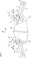
FIG. 4 is a rear view of the optical sensor disposition structure according to the embodiment. -
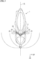
FIG. 5 is a view for describing photographing ranges of left and right rear-photographing cameras according to the embodiment. -
FIG. 6 is a left side view of the optical sensor disposition structure according to the embodiment. -
FIG. 7 is a right side view of the optical sensor disposition structure according to the embodiment. -
FIG. 8 is a view for describing photographing ranges of left and right lateral-photographing cameras according to the embodiment. -
FIG. 9 is a view including a cross section taken along line IX-IX ofFIG. 2 . -
FIG. 10 is a view including a cross section taken along line X-X ofFIG. 2 . -
FIG. 11 is a perspective view of the optical sensor disposition structure according to the embodiment when seen from a left rear side. - Hereinafter, an embodiment of the present invention will be described based on the accompanying drawings. Further, directions of forward, rearward, left, right, and so on, described below are the same as directions in a vehicle described below unless the context clearly indicates otherwise. In addition, in appropriate places in the drawings used in the following description, an arrow FR showing a forward direction with respect to a vehicle, an arrow LH showing a leftward direction with respect to the vehicle and an arrow UP showing an upward direction with respect to the vehicle are provided.
-
FIG. 1 shows ascooter type motorcycle 1 serving as an example of a saddle riding vehicle. Hereinafter, themotorcycle 1 may be simply referred to as "a vehicle." - As shown in
FIG. 1 , themotorcycle 1 includes steering system parts including a handle bar pipe 2 (handle bar) and afront wheel 3 supported at a head pipe of a front end of a vehicle body frame (not shown) to be steerable, a front cowl 4 configured to cover a vehicle body front section, and an opticalsensor disposition structure 20, which will be described below. - The
handle bar pipe 2 is supported at an upper end portion of asteering shaft 5 inserted through a head pipe (not shown) via a handle bar holder 6 (seeFIG. 11 ). - The
front wheel 3 is axially supported at lower end portions of a pair of left andright front forks 7. - A
bridge member 8 extending in a vehicle width direction is connected to a lower end portion of thesteering shaft 5 exposed from the head pipe. - Upper end portions of the left and
right front forks 7 are respectively connected to left and right sides of thebridge member 8. - The front cowl 4 covers a front upper section of a vehicle body frame from a front side toward the both of left and right sides.
- A
garnish 9 having an introduction port configured to guide traveling air rearward, ameter visor 10 disposed above thegarnish 9 and aheadlight 11 disposed below thegarnish 9 are attached to the front cowl 4. - When seen in a front view, the
headlight 11 is formed in a U shape having an upper edge formed along a lower edge of thegarnish 9. - Further, reference numeral 12 in the drawings designates a pair of left and right rearview mirrors,
reference numeral 13 in the drawings designates a clutch lever,reference numeral 14 in the drawings designates a brake lever,reference numeral 15 in the drawings designates a reservoir tank of a brake master cylinder, andreference numeral 16 in the drawings designates a front fender. -
FIG. 2 shows a camera disposition structure including cameras that can photograph objects or the like around the vehicle as an example of the opticalsensor disposition structure 20. - As shown in
FIG. 2 , the opticalsensor disposition structure 20 includescameras 31 and 32 (optical sensors) disposed on a vehicle body front section, left and righthandle bar grips handle bar pipe 2, and left andright switch cases handle bar grips handle bar pipe 2. - When seen in a front view of
FIG. 2 , the left and righthandle bar grips - The left and
right switch cases right rearview mirrors - The
motorcycle 1 includes adriving support system 30 using a camera. The drivingsupport system 30 includes left and right front-photographingcameras 31 and 32 (seeFIG. 2 ), left and right rear-photographingcameras 33 and 34 (seeFIG. 4 ), and left and right lateral-photographingcameras 35 and 36 (seeFIG. 6 andFIG. 7 ). Hereinafter, the left and right front-photographing cameras, the left and right rear-photographing cameras, and the left and right lateral-photographing cameras may be simply referred to as "cameras." - The
cameras support system 30. - Based on the images photographed by the
cameras - The image processor outputs processing information to a command section of the control device. The command section outputs commands for performing driving support such as brake control, steering control, and so on, to prevent collision of the vehicle, various warnings to an occupant, and so on, to respective parts of the vehicle. Further, the driving
support system 30 may be linked to a navigation system and a cruise control system. Thecameras - The
cameras switch cases cameras main bodies switch cases lenses main bodies switch cases - Referring to both
FIG. 2 andFIG. 3 , the left and right front-photographingcameras cameras support system 30 is capable of detecting an object or the like in front of the vehicle by photographing a front of the vehicle using the left and right front-photographingcameras support system 30 is capable of performing an image synthesis based on the images photographed by the left and right front-photographingcameras - When seen in the front view of
FIG. 2 , the left and right front-photographingcameras handle bar pipe 2. That is, the left and right front-photographingcameras handle bar pipe 2. The axis C1 of thehandle bar pipe 2 coincides with central axes of thehandle bar grips - When seen in the front view of
FIG. 2 , the left front-photographingcamera 31 is installed on the front upper section of theleft switch case 23 on the outer side in the vehicle width direction. Specifically, when seen in a front view ofFIG. 2 , the left front-photographingcamera 31 is disposed at an upper part than aclutch lever 13 and at more left side than thesupport stay 12a of the leftrearview mirror 12L. - The
lens 31b of the left front-photographingcamera 31 is exposed toward the front side from theleft switch case 23. That is, a member and the like that blocks a field of vision of the left front-photographingcamera 31 is not disposed in front of the left front-photographingcamera 31. For this reason, the left front-photographingcamera 31 is capable of photographing an object or the like in front of the vehicle with a wide field of vision. - When seen in the front view of
FIG. 2 , thelens 31b of the left front-photographingcamera 31 is formed in a circular shape. Avisor section 31c formed in an arcuate shape along an outer circumference of thelens 31b when seen in the front view ofFIG. 2 and configured to cover a front upper side of thelens 31b is formed on theleft switch case 23. - When seen in the front view of
FIG. 2 , the right front-photographingcamera 32 is installed on a front upper section of theright switch case 24 on the outer side in the vehicle width direction. Specifically, when seen in the front view ofFIG. 2 , the right front-photographingcamera 32 is disposed at an upper part than abrake lever 14 and at more a right side than thesupport stay 12a of the rightrearview mirror 12R. - The
lens 32b of the right front-photographingcamera 32 is exposed toward the front side from theright switch case 24. That is, a member or the like that blocks a field of vision of the right front-photographingcamera 32 is not disposed in front of the right front-photographingcamera 32. For this reason, the right front-photographingcamera 32 is capable of photographing an object or the like in front of the vehicle with a wide field of vision. - When seen in the front view of
FIG. 2 , thelens 32b of the right front-photographingcamera 32 is formed in a circular shape. Anvisor section 32c formed in an arcuate shape along an outer circumference of thelens 32b when seen in the front view ofFIG. 2 and configured to cover a front upper side of thelens 32b is formed on theright switch case 24. - As shown in
FIG. 3 , photographing ranges of the left and right front-photographingcameras FIG. 3 , a viewing angle (an angle of field) of the left and right front-photographingcameras - The rear-photographing cameras will be described with reference to both
FIG. 4 andFIG. 5 . The left and right rear-photographingcameras cameras support system 30 is capable of detecting an object or the like behind the vehicle by photographing a behind of the vehicle using the left and right rear-photographingcameras support system 30 is capable of performing an image synthesis based on the images photographed by the left and right rear-photographingcameras - When seen in a rear view of
FIG. 4 , the left and right rear-photographingcameras handle bar pipe 2. That is, the left and right rear-photographingcameras axis C 1 of thehandle bar pipe 2. - When seen in the rear view of
FIG. 4 , a horn switch 41 (a shaft section switch), a dimmer switch 42 (an upper switch) configured to switch between a high beam and a low beam, and ablinker switch 43 are installed on theleft switch case 23. - When seen in the rear view of
FIG. 4 , thehorn switch 41 is installed at a position overlapping the axis C1 of the handle bar pipe 2 (in other words, a central axis of a left handle bar grip 21). Thedimmer switch 42 is installed on an upper section of theleft switch case 23. Theblinker switch 43 is installed on a lower section of theleft switch case 23. - When seen in the rear view of
FIG. 4 , the left rear-photographingcamera 33 is installed above thehorn switch 41 and more inward than thedimmer switch 42 in the vehicle width direction. That is, the left rear-photographingcamera 33 is installed on a rear upper section of theleft switch case 23 on the inner side in the vehicle width direction. - The
lens 33b of the left rear-photographingcamera 33 is exposed toward the rear side from theleft switch case 23. That is, a member or the like that blocks a field of vision of the left rear-photographingcamera 33 is not disposed behind the left rear-photographingcamera 33. For this reason, the left rear-photographingcamera 33 is capable of photographing an object or the like behind the vehicle with a wide field of vision. - When seen in the rear view of
FIG. 4 , thelens 33b of the left rear-photographingcamera 33 is formed in a circular shape. Anvisor section 33c formed in arcuate shape along an outer circumference of thelens 33b when seen in the rear view ofFIG. 4 and configured to cover a rear upper side of thelens 33b is formed on theleft switch case 23. - When seen in the rear view of
FIG. 4 , a hazard switch 44 (a shaft section switch), an emergency stop switch 45 (an upper switch) and astarter switch 46 are installed on theright switch case 24. - When seen in the rear view of
FIG. 4 , thehazard switch 44 is installed at a position overlapping the axis C1 of the handle bar pipe 2 (in other words, a central axis of a right handle bar grip 22). Theemergency stop switch 45 is installed on an upper section of theright switch case 24. Thestarter switch 46 is installed on a lower section of theright switch case 24. - When seen in the rear view of
FIG. 4 , the right rear-photographingcamera 34 is installed above thehazard switch 44 and more inward than theemergency stop switch 45 in the vehicle width direction. That is, the right rear-photographingcamera 34 is installed on a rear upper section of theright switch case 24 on the inner side in the vehicle width direction. - The lens 34b of the right rear-photographing
camera 34 is exposed toward the rear side from theright switch case 24. That is, a member or the like that blocks a field of vision of the right rear-photographingcamera 34 is not disposed behind the right rear-photographingcamera 34. For this reason, the right rear-photographingcamera 34 is capable of photographing an object or the like behind the vehicle with a wide field of vision. - When seen in the rear view of
FIG. 4 , the lens 34b of the right rear-photographingcamera 34 is formed in a circular shape. Anvisor section 34c formed in an arcuate shape along an outer circumference of the lens 34b when seen in the rear view ofFIG. 4 and configured to cover a rear upper side of the lens 34b is formed on theright switch case 24. - As shown in
FIG. 5 , photographing ranges of the left and right rear-photographingcameras FIG. 5 , a viewing angle (an angle of field) of the left and right rear-photographingcameras - The lateral-photographing cameras will be described with reference to all of
FIG. 6 to FIG. 8 . The left and right lateral-photographingcameras support system 30 is capable of detecting objects or the like on left and right sides of the vehicle by photographing the left and right sides of the vehicle using the left and right lateral-photographingcameras support system 30 is capable of performing image synthesis based on the images photographed by the left and right lateral-photographingcameras - When seen in the side views of
FIG. 6 andFIG. 7 , the left and right lateral-photographingcameras FIG. 4 ). That is, the left and right lateral-photographingcameras handle bar pipe 2. Hereinafter, the left lateral-photographing camera may be referred to as "a left photographing camera" and the right lateral-photographing camera may be referred to as "a right photographing camera." - When seen in a left side view of
FIG. 6 , theleft photographing camera 35 is installed on a front upper section of an outer end portion of theleft switch case 23 in the vehicle width direction. Specifically, when seen in the left side view ofFIG. 6 , theleft photographing camera 35 is disposed on a front upper side of the lefthandle bar grip 21, and disposed above theclutch lever 13 and behind thesupport stay 12a of the leftrearview mirror 12L. - The
lens 35b of theleft photographing camera 35 is exposed toward the left side from theleft switch case 23. That is, a member or the like that blocks a field of vision of theleft photographing camera 35 is not disposed on the left side of theleft photographing camera 35. For this reason, theleft photographing camera 35 is capable of photographing an object or the like on the left side of the vehicle with a wide field of vision. - When seen in the left side view of
FIG. 6 , thelens 35b of theleft photographing camera 35 is formed in a circular shape. Anvisor section 35c formed in an arcuate shape along an outer circumference of thelens 35b when seen in the left side view ofFIG. 6 and configured to cover a left upper side of thelens 35b is formed on theleft switch case 23. - When seen in the right side view of
FIG. 7 , theright photographing camera 36 is formed on a front upper section of an outer end portion of theright switch case 24 in the vehicle width direction. Specifically, when seen in the right side view ofFIG. 7 , theright photographing camera 36 is disposed on a front upper side of the righthandle bar grip 22, and disposed above thebrake lever 14 and behind thesupport stay 12a of the rightrearview mirror 12R. - The
lens 36b of theright photographing camera 36 is exposed toward the right side from theright switch case 24. That is, a member or the like that blocks a field of vision of theright photographing camera 36 is not disposed on a right side of theright photographing camera 36. For this reason, theright photographing camera 36 can photograph an object or the like on the right side of the vehicle with a wide field of vision. - When seen in the right side view of
Fig. 7 , thelens 36b of theright photographing camera 36 is formed in a circular shape. Anvisor section 36c formed in an arcuate shape along an outer circumference of thelens 36b when seen in the right side view ofFIG. 7 and configured to cover a right upper side of thelens 36b is formed on theright switch case 24. - As shown in
FIG. 8 , photographing ranges of the left and right lateral-photographingcameras FIG. 8 , a viewing angle (an angle of field) of the left and right lateral-photographingcameras -
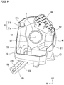
FIG. 9 is a view including a cross section taken along line IX-IX ofFIG. 2 . That is,FIG. 9 is a view including a cross section obtained by cutting theleft switch case 23 along a plane perpendicular to theaxis C 1 of thehandle bar pipe 2. - When seen in a cross-sectional view of
FIG. 9 , theleft switch case 23 is formed in an annular shape having an external shape larger than that of thehandle bar pipe 2. A cameramain body 31a of the left front-photographingcamera 31 is installed inside theleft switch case 23 and installed in front of thedimmer switch 42. - A
horn switch harness 51 connected to thehorn switch 41, adimmer switch harness 52 connected to thedimmer switch 42, ablinker switch harness 53 connected to theblinker switch 43, a left front-photographingcamera harness 57 connected to the left front-photographingcamera 31, a left rear-photographing camera harness (not shown) connected to the left rear-photographing camera 33 (seeFIG. 4 ), and a left lateral-photographing camera harness (not shown) connected to the left photographing camera 35 (seeFIG. 4 ) are routed in a space around thehandle bar pipe 2 inside theleft switch case 23. - The
horn switch harness 51, thedimmer switch harness 52 and theblinker switch harness 53 are bundled together to constitute aleft switch harness 61L. - The
left switch harness 61L is drawn outside from theleft switch case 23, extends toward the vehicle body and is connected to a power supply unit (not shown).Reference numeral 65 in the drawings designates a tubular protective tube having flexibility and configured to cover theleft switch harness 61 L. - The left front-photographing
camera harness 57, the left rear-photographing camera harness (not shown) and the left lateral-photographing camera harness (not shown) are bundled together to constitute aleft camera harness 62L. Theleft camera harness 62L is drawn outside from theleft switch case 23, extends toward the vehicle body along theleft switch harness 61L and is connected to a power supply unit (not shown).Reference numeral 66 in the drawings designates a tubular protective tube having flexibility and configured to cover theleft camera harness 62L. -
FIG. 10 is a view including a cross section taken along line X-X ofFIG. 2 . That is,FIG. 10 is a view including a cross section obtained by cutting theright switch case 24 along a plane perpendicular to theaxis C 1 of thehandle bar pipe 2. - When seen in a cross-sectional view of
FIG. 10 , theright switch case 24 is formed in an annular shape having an external shape larger than that of thehandle bar pipe 2. The cameramain body 32a of the right front-photographingcamera 32 is installed inside of theright switch case 24 and installed in front of theemergency stop switch 45. - A
hazard switch harness 54 connected to thehazard switch 44, an emergencystop switch harness 55 connected to theemergency stop switch 45, astarter switch harness 56 connected to thestarter switch 46, a right front-photographingcamera harness 58 connected to the right front-photographingcamera 32, a right rear-photographing camera harness (not shown) connected to the right rear-photographing camera 34 (seeFIG. 4 ), and a right lateral-photographing camera harness (not shown) connected to the right photographing camera 36 (seeFIG. 4 ) are routed in a space around thehandle bar pipe 2 inside theright switch case 24. - The
hazard switch harness 54, the emergencystop switch harness 55 and thestarter switch harness 56 are bundled together to constitute aright switch harness 61R. Theright switch harness 61R is drawn outside of theright switch case 24, extends toward the vehicle body and is connected to a power supply unit (not shown).Reference numeral 67 in the drawings designates a tubular protective tube having flexibility and configured to cover theright switch harness 61R. - The right front-photographing
camera harness 58, the right rear-photographing camera harness (not shown) and the right lateral-photographing camera harness (not shown) are bundled together to constitute aright camera harness 62R. Theright camera harness 62R is drawn outside of theright switch case 24, extends toward the vehicle body along theright switch harness 61R and is connected to a power supply unit (not shown).Reference numeral 68 in the drawings designates a tubular protective tube having flexibility and configured to cover theright camera harness 62R. Further,reference numerals - A surrounding structure of the right switch case will be described with reference to both
FIG. 4 andFIG. 11 . The right rear-photographingcamera 34 is disposed in the vicinity of aninspection window 15a installed at areservoir tank 15. Accordingly, in comparison with a case in which the right rear-photographingcamera 34 is disposed at a position far from theinspection window 15a, since the right rear-photographingcamera 34 can be inconspicuous, the appearance can be improved. Further,reference numeral 17 in the drawings designates a meter unit including gauges of various kinds and an information display unit, andreference numeral 18 in the drawings designates a leg shield. - As described above, the optical
sensor disposition structure 20 of themotorcycle 1 of the embodiment includes thecameras handle bar grips handle bar pipe 2, and theswitch cases handle bar grips handle bar pipe 2, and thecameras switch cases - According to the above-mentioned configuration, as the
cameras switch cases handle bar pipe 2, a periphery of the handle bar can be minimized. In addition, in comparison with the case in which a separate stay is installed, the appearance can be improved. - In addition, while the harnesses (for example, the left and right camera harnesses 62L and 62R) connected to the
cameras cameras harnesses - In addition, since the
harnesses cameras switch cases - In addition, in comparison with a case in which a portable information terminal device having a built-in camera is installed, since a dead angle does not occur in a field of vision of an occupant due to the portable information terminal device, it is possible to prevent the
meter unit 17 from being inconspicuous. - In addition, since the dead angle does not occur in detection regions of the
cameras meter unit 17, theheadlight 11, and so on, detectable ranges of thecameras - In addition, in the embodiment, as the
cameras main bodies switch cases lenses main bodies switch cases cameras main bodies cameras - In addition, in the embodiment, as the
cameras handle bar pipe 2, occurrence of the dead angle in the detection regions of thecameras cameras - In addition, in the embodiment, as the
camera 33 is installed above thehorn switch 41 and thecamera 34 is installed above thehazard switch 44, even when an occupant operates thehorn switch 41 or thehazard switch 44, the detection regions of thecameras cameras - In addition, in the embodiment, as the
camera 33 is installed more inward than thedimmer switch 42 in the vehicle width direction and thecamera 34 is installed more inward than theemergency stop switch 45 in the vehicle width direction, even when the occupant manipulates thedimmer switch 42 or theemergency stop switch 45, the detection regions of thecameras cameras camera 33 is installed more outward than thedimmer switch 42 in the vehicle width direction and thecamera 34 is installed more outward than theemergency stop switch 45 in the vehicle width direction, routing distances of the harnesses connected to thecameras - Further, in the embodiment, while the example in which the left and right front-photographing cameras, the left and right rear-photographing cameras and the left and right lateral-photographing cameras are installed in the switch case has been exemplarily described, there is no limitation thereto.
- For example, only the left and right front-photographing cameras may be installed in the switch case. That is, at least one of the left and right front-photographing camera, the left and right rear-photographing camera, and the left and right lateral-photographing camera may be installed in the switch case.
- In addition, in the embodiment, while the example in which the right rear-photographing camera is disposed in the vicinity of the inspection window installed on the reservoir tank has been exemplarily described, there is no limitation thereto.
- For example, when a clutch master cylinder is installed, the left rear-photographing camera may be disposed in the vicinity of the inspection window installed on the reservoir tank of the clutch master cylinder. Even in this case, since the left rear-photographing camera can be inconspicuous, the appearance can be improved.
- In addition, in the embodiment, while the example in which the camera includes the camera main body installed inside the switch case has been exemplarily described, there is no limitation thereto.
- For example, the camera may include a camera main body exposed on the outside of the switch case. Even in this case, when the camera main body and the switch case have substantially the same color (for example, black), since the camera is inconspicuous, the appearance can be improved.
- Further, the present invention is not limited to the embodiment and, for example, the camera may be a camera configured to capture invisible light such as infrared light or the like in addition to visible light. In addition to the camera, an optical sensor such as a radar or the like using infrared light, millimeter waves, or the like, may be provided. A configuration using a single optical sensor rather than a pair of left and right optical sensors may be provided. A configuration in which the camera and the radar are combined may be provided. The disposition of lenses of the cameras in the embodiment is a disposition of antennae in the case of radar.
- All vehicles in which a driver rides across the vehicle body are included as the saddle riding vehicle, and in addition to a motorcycle (including a motorized bicycle and a scooter type vehicle), a three-wheeled vehicle (including a two-front-wheeled and one-rear-wheeled vehicle in addition to a one-front-wheeled and two-rear-wheeled vehicle) are also included.
- While preferred embodiments of the invention have been described and illustrated above, it should be understood that these are exemplary of the invention and are not to be considered as limiting. Additions, omissions, substitutions, and other modifications can be made without departing from the scope of the present invention. An optical sensor disposition structure (20) of a saddle riding vehicle (1) includes an optical sensor (31, 32), left and right handle bar grips (21, 22) installed on both side portions of a handle bar pipe (2), and a switch case (23, 24) installed between the left and right handle bar grips (21, 22) and supported by the handle bar pipe (2), and the optical sensor (31, 32) is installed on the switch case (23, 24).
Claims (5)
- An optical sensor disposition structure (20) for a saddle riding vehicle (1) including a handle bar (2), the optical sensor disposition structure comprising:an optical sensor (31, 32, 33, 34, 35, 36);left and right handle bar grips (21, 22) installed on both side portions of the handle bar (2); anda switch case (23, 24) installed between the left and right handle bar grips (21, 22) and supported by the handle bar (2),wherein the optical sensor (31, 32, 33, 34, 35, 36) is installed at the switch case (23, 24).
- The optical sensor disposition structure for a saddle riding vehicle according to claim 1,wherein the optical sensor (31, 32, 33, 34, 35, 36) comprises:a main body section (31a, 32a, 33a, 34a, 35a, 36a) installed inside the switch case (23, 24); anda lens (31b, 32b, 33b, 34b, 35b, 36b) attached to the main body section (31a, 32a, 33a, 34a, 35a, 36a) and exposed toward an outside of the switch case (23, 24).
- The optical sensor disposition structure for a saddle riding vehicle according to claim 1 or 2,wherein the optical sensor (31, 32, 33, 34, 35, 36) is installed above the handle bar (2).
- The optical sensor disposition structure for a saddle riding vehicle according to any one of claims 1 to 3,wherein, when seen in a rear view, a shaft section switch (41, 44) is installed at a position overlapping an axis (C1) of the handle bar (2), andthe optical sensor (33, 34) is installed above the shaft section switch (41, 44).
- The optical sensor disposition structure for a saddle riding vehicle according to any one of claims 1 to 4,wherein, when seen in a rear view, an upper switch (42, 45) is installed at an upper section of the switch case (23, 24), andthe optical sensor (33, 34) is installed more inward than the upper switch (42, 45) in a vehicle width direction.
Applications Claiming Priority (1)
| Application Number | Priority Date | Filing Date | Title |
|---|---|---|---|
| JP2016097420A JP6543823B2 (en) | 2016-05-13 | 2016-05-13 | Optical sensor arrangement structure of straddle type vehicle |
Publications (2)
| Publication Number | Publication Date |
|---|---|
| EP3243733A1 true EP3243733A1 (en) | 2017-11-15 |
| EP3243733B1 EP3243733B1 (en) | 2019-12-18 |
Family
ID=58709794
Family Applications (1)
| Application Number | Title | Priority Date | Filing Date |
|---|---|---|---|
| EP17170244.2A Active EP3243733B1 (en) | 2016-05-13 | 2017-05-09 | Optical sensor disposition structure for saddle riding vehicle |
Country Status (3)
| Country | Link |
|---|---|
| US (1) | US10562582B2 (en) |
| EP (1) | EP3243733B1 (en) |
| JP (1) | JP6543823B2 (en) |
Families Citing this family (12)
| Publication number | Priority date | Publication date | Assignee | Title |
|---|---|---|---|---|
| WO2015186213A1 (en) * | 2014-06-04 | 2015-12-10 | 株式会社エフ・シ-・シ- | Saddled vehicle |
| US10562477B2 (en) * | 2016-06-24 | 2020-02-18 | Honda Motor Co., Ltd. | Optical sensor supporting structure for saddled vehicle |
| WO2019180829A1 (en) * | 2018-03-20 | 2019-09-26 | 本田技研工業株式会社 | Saddle riding-type vehicle |
| WO2019186799A1 (en) * | 2018-03-28 | 2019-10-03 | 本田技研工業株式会社 | Object detection system for saddle-type vehicle, and saddle-type vehicle |
| DE112018007390B4 (en) * | 2018-03-29 | 2023-08-24 | Honda Motor Co., Ltd. | straddle vehicle |
| JP7084476B2 (en) * | 2018-05-23 | 2022-06-14 | 本田技研工業株式会社 | Saddle-type vehicle |
| WO2020041191A1 (en) * | 2018-08-20 | 2020-02-27 | Indian Motorcycle International, LLC | Wheeled vehicle notification system and method |
| US11866042B2 (en) | 2018-08-20 | 2024-01-09 | Indian Motorcycle International, LLC | Wheeled vehicle adaptive speed control method and system |
| JP6865728B2 (en) * | 2018-12-21 | 2021-04-28 | 川崎重工業株式会社 | Saddle-type vehicle |
| CN114987664A (en) * | 2022-06-30 | 2022-09-02 | 广东宙斯科技有限公司 | Motorcycle instrument with rearview function |
| JP2025146255A (en) * | 2024-03-22 | 2025-10-03 | 株式会社Jvcケンウッド | Driving assistance devices |
| WO2026013917A1 (en) * | 2024-07-12 | 2026-01-15 | Astemo株式会社 | Imaging device for straddled vehicle and driving support system for straddled vehicle |
Citations (2)
| Publication number | Priority date | Publication date | Assignee | Title |
|---|---|---|---|---|
| DE20319228U1 (en) * | 2003-12-11 | 2004-03-04 | K.W. Hochschorner Gmbh | Camera 910) for cycles and leisure equipment use has miniature CCD camera on adjustable bracket with image memory and external infrared interface |
| JP2013203170A (en) | 2012-03-28 | 2013-10-07 | Honda Motor Co Ltd | Method for determining installation position of portable information terminal on vehicle |
Family Cites Families (22)
| Publication number | Priority date | Publication date | Assignee | Title |
|---|---|---|---|---|
| JPS61162777A (en) * | 1985-01-12 | 1986-07-23 | Yamaha Motor Co Ltd | Recognition for running environment of vehicle |
| US4854702A (en) * | 1987-12-14 | 1989-08-08 | Hunter Engineering Company | Vehicle wheel alignment apparatus and method of use |
| US6498620B2 (en) * | 1993-02-26 | 2002-12-24 | Donnelly Corporation | Vision system for a vehicle including an image capture device and a display system having a long focal length |
| US7065462B2 (en) * | 1998-07-24 | 2006-06-20 | Merilab, Inc. | Vehicle wheel alignment by rotating vision sensor |
| US6134792A (en) * | 1998-11-19 | 2000-10-24 | Hunter Engineering Company | Method and apparatus for determining wheel alignment optical target orientation parameters |
| US6974222B2 (en) * | 2003-03-31 | 2005-12-13 | Honda Motor Company, Ltd. | Light distribution plenum for an illuminated control assembly and method |
| JP4321128B2 (en) * | 2003-06-12 | 2009-08-26 | 株式会社デンソー | Image server, image collection device, and image display terminal |
| US7474205B2 (en) * | 2004-03-24 | 2009-01-06 | Richard Steven Trela | Stand-off vehicle under-carriage inspection and detection system for deterring vehicle bombers from a safe stand-off distance |
| JP2006103600A (en) * | 2004-10-07 | 2006-04-20 | Yamaha Motor Co Ltd | Motorcycle front view device |
| US20060152711A1 (en) * | 2004-12-30 | 2006-07-13 | Dale James L Jr | Non-contact vehicle measurement method and system |
| US20070040911A1 (en) * | 2005-01-31 | 2007-02-22 | Riley Larry E | Under vehicle inspection system |
| CA2599856A1 (en) * | 2005-02-24 | 2006-09-08 | Perceptics, Llc | Apparatus and method for capturing and displaying images of the undercarriage of vehicles |
| US20100079266A1 (en) * | 2008-09-30 | 2010-04-01 | Holt Richard K | Motorcycle accident warning alarm |
| JP4831797B2 (en) | 2009-01-30 | 2011-12-07 | 株式会社村上開明堂 | door mirror |
| JP5378903B2 (en) * | 2009-08-04 | 2013-12-25 | ヤマハ発動機株式会社 | Motorcycle |
| US9244133B2 (en) * | 2011-01-13 | 2016-01-26 | Icove And Associates, Llc | Handheld devices and structures to detect sticky devices having magnets |
| JP2013006466A (en) * | 2011-06-23 | 2013-01-10 | Asahi Denso Co Ltd | Switch device for handlebar |
| JP6123422B2 (en) * | 2013-03-29 | 2017-05-10 | 市光工業株式会社 | Peripheral field of view confirmation device for vehicles |
| JP5517377B2 (en) * | 2013-05-17 | 2014-06-11 | カヤバ工業株式会社 | Drive recorder |
| TWM484538U (en) * | 2013-09-09 | 2014-08-21 | Ken Sean Ind Co Ltd | Handlebar type vehicle rearview mirror having driving monitoring function and handlebar type vehicle |
| JP6000307B2 (en) * | 2014-08-29 | 2016-09-28 | 本田技研工業株式会社 | Switch device for handle |
| US9452801B2 (en) * | 2014-11-10 | 2016-09-27 | Rock Langevin | Motorcycle safety system with incorporated camera and video recording |
-
2016
- 2016-05-13 JP JP2016097420A patent/JP6543823B2/en active Active
-
2017
- 2017-05-09 EP EP17170244.2A patent/EP3243733B1/en active Active
- 2017-05-10 US US15/591,748 patent/US10562582B2/en active Active
Patent Citations (2)
| Publication number | Priority date | Publication date | Assignee | Title |
|---|---|---|---|---|
| DE20319228U1 (en) * | 2003-12-11 | 2004-03-04 | K.W. Hochschorner Gmbh | Camera 910) for cycles and leisure equipment use has miniature CCD camera on adjustable bracket with image memory and external infrared interface |
| JP2013203170A (en) | 2012-03-28 | 2013-10-07 | Honda Motor Co Ltd | Method for determining installation position of portable information terminal on vehicle |
Also Published As
| Publication number | Publication date |
|---|---|
| EP3243733B1 (en) | 2019-12-18 |
| US20170327177A1 (en) | 2017-11-16 |
| JP6543823B2 (en) | 2019-07-17 |
| JP2017202809A (en) | 2017-11-16 |
| US10562582B2 (en) | 2020-02-18 |
Similar Documents
| Publication | Publication Date | Title |
|---|---|---|
| EP3243733B1 (en) | Optical sensor disposition structure for saddle riding vehicle | |
| EP3243731B1 (en) | Optical sensor disposition structure for saddle riding vehicle | |
| EP3476708B1 (en) | Optical sensor supporting structure for saddled vehicles | |
| EP3183875B1 (en) | Display system and method | |
| CN108602465B (en) | Image display system for vehicle and vehicle equipped with the image display system | |
| US10919528B2 (en) | Vehicle driving assistance device and vehicle | |
| JP7163748B2 (en) | Vehicle display control device | |
| CN102081861B (en) | On-vehicle device and recognition support system | |
| US10882450B2 (en) | Vehicle periphery monitoring apparatus | |
| WO2016002163A1 (en) | Image display device and image display method | |
| JPWO2017061230A1 (en) | Display support apparatus and display support method | |
| US11601621B2 (en) | Vehicular display system | |
| US11167815B2 (en) | Saddled vehicle | |
| EP3508406B1 (en) | Saddle-type vehicle | |
| WO2017061183A1 (en) | Human interface | |
| EP4182208B1 (en) | Blind spot detection system | |
| JPH08253059A (en) | Vehicle driving support system | |
| JP4379148B2 (en) | Rear confirmation device | |
| WO2013144998A1 (en) | Visual recognition assistance apparatus for vehicle | |
| EP1456058A1 (en) | Vehicle imaging system | |
| JP5821622B2 (en) | Obstacle alarm device | |
| WO2013191079A1 (en) | Vehicle vicinity viewing device | |
| JP7758491B2 (en) | Video display control system and video display control method | |
| KR20150074753A (en) | Driver assistance apparatus and Vehicle including the same | |
| JP2006159933A (en) | Vehicle periphery display support system |
Legal Events
| Date | Code | Title | Description |
|---|---|---|---|
| PUAI | Public reference made under article 153(3) epc to a published international application that has entered the european phase |
Free format text: ORIGINAL CODE: 0009012 |
|
| STAA | Information on the status of an ep patent application or granted ep patent |
Free format text: STATUS: REQUEST FOR EXAMINATION WAS MADE |
|
| 17P | Request for examination filed |
Effective date: 20170509 |
|
| AK | Designated contracting states |
Kind code of ref document: A1 Designated state(s): AL AT BE BG CH CY CZ DE DK EE ES FI FR GB GR HR HU IE IS IT LI LT LU LV MC MK MT NL NO PL PT RO RS SE SI SK SM TR |
|
| AX | Request for extension of the european patent |
Extension state: BA ME |
|
| STAA | Information on the status of an ep patent application or granted ep patent |
Free format text: STATUS: EXAMINATION IS IN PROGRESS |
|
| 17Q | First examination report despatched |
Effective date: 20190118 |
|
| GRAP | Despatch of communication of intention to grant a patent |
Free format text: ORIGINAL CODE: EPIDOSNIGR1 |
|
| STAA | Information on the status of an ep patent application or granted ep patent |
Free format text: STATUS: GRANT OF PATENT IS INTENDED |
|
| INTG | Intention to grant announced |
Effective date: 20190805 |
|
| GRAS | Grant fee paid |
Free format text: ORIGINAL CODE: EPIDOSNIGR3 |
|
| GRAA | (expected) grant |
Free format text: ORIGINAL CODE: 0009210 |
|
| STAA | Information on the status of an ep patent application or granted ep patent |
Free format text: STATUS: THE PATENT HAS BEEN GRANTED |
|
| AK | Designated contracting states |
Kind code of ref document: B1 Designated state(s): AL AT BE BG CH CY CZ DE DK EE ES FI FR GB GR HR HU IE IS IT LI LT LU LV MC MK MT NL NO PL PT RO RS SE SI SK SM TR |
|
| REG | Reference to a national code |
Ref country code: CH Ref legal event code: EP |
|
| REG | Reference to a national code |
Ref country code: IE Ref legal event code: FG4D |
|
| REG | Reference to a national code |
Ref country code: DE Ref legal event code: R096 Ref document number: 602017009749 Country of ref document: DE |
|
| REG | Reference to a national code |
Ref country code: AT Ref legal event code: REF Ref document number: 1214313 Country of ref document: AT Kind code of ref document: T Effective date: 20200115 |
|
| REG | Reference to a national code |
Ref country code: NL Ref legal event code: MP Effective date: 20191218 |
|
| PG25 | Lapsed in a contracting state [announced via postgrant information from national office to epo] |
Ref country code: LT Free format text: LAPSE BECAUSE OF FAILURE TO SUBMIT A TRANSLATION OF THE DESCRIPTION OR TO PAY THE FEE WITHIN THE PRESCRIBED TIME-LIMIT Effective date: 20191218 Ref country code: GR Free format text: LAPSE BECAUSE OF FAILURE TO SUBMIT A TRANSLATION OF THE DESCRIPTION OR TO PAY THE FEE WITHIN THE PRESCRIBED TIME-LIMIT Effective date: 20200319 Ref country code: NO Free format text: LAPSE BECAUSE OF FAILURE TO SUBMIT A TRANSLATION OF THE DESCRIPTION OR TO PAY THE FEE WITHIN THE PRESCRIBED TIME-LIMIT Effective date: 20200318 Ref country code: BG Free format text: LAPSE BECAUSE OF FAILURE TO SUBMIT A TRANSLATION OF THE DESCRIPTION OR TO PAY THE FEE WITHIN THE PRESCRIBED TIME-LIMIT Effective date: 20200318 Ref country code: LV Free format text: LAPSE BECAUSE OF FAILURE TO SUBMIT A TRANSLATION OF THE DESCRIPTION OR TO PAY THE FEE WITHIN THE PRESCRIBED TIME-LIMIT Effective date: 20191218 Ref country code: SE Free format text: LAPSE BECAUSE OF FAILURE TO SUBMIT A TRANSLATION OF THE DESCRIPTION OR TO PAY THE FEE WITHIN THE PRESCRIBED TIME-LIMIT Effective date: 20191218 Ref country code: FI Free format text: LAPSE BECAUSE OF FAILURE TO SUBMIT A TRANSLATION OF THE DESCRIPTION OR TO PAY THE FEE WITHIN THE PRESCRIBED TIME-LIMIT Effective date: 20191218 |
|
| REG | Reference to a national code |
Ref country code: LT Ref legal event code: MG4D |
|
| PG25 | Lapsed in a contracting state [announced via postgrant information from national office to epo] |
Ref country code: RS Free format text: LAPSE BECAUSE OF FAILURE TO SUBMIT A TRANSLATION OF THE DESCRIPTION OR TO PAY THE FEE WITHIN THE PRESCRIBED TIME-LIMIT Effective date: 20191218 Ref country code: HR Free format text: LAPSE BECAUSE OF FAILURE TO SUBMIT A TRANSLATION OF THE DESCRIPTION OR TO PAY THE FEE WITHIN THE PRESCRIBED TIME-LIMIT Effective date: 20191218 |
|
| PG25 | Lapsed in a contracting state [announced via postgrant information from national office to epo] |
Ref country code: AL Free format text: LAPSE BECAUSE OF FAILURE TO SUBMIT A TRANSLATION OF THE DESCRIPTION OR TO PAY THE FEE WITHIN THE PRESCRIBED TIME-LIMIT Effective date: 20191218 |
|
| PG25 | Lapsed in a contracting state [announced via postgrant information from national office to epo] |
Ref country code: EE Free format text: LAPSE BECAUSE OF FAILURE TO SUBMIT A TRANSLATION OF THE DESCRIPTION OR TO PAY THE FEE WITHIN THE PRESCRIBED TIME-LIMIT Effective date: 20191218 Ref country code: NL Free format text: LAPSE BECAUSE OF FAILURE TO SUBMIT A TRANSLATION OF THE DESCRIPTION OR TO PAY THE FEE WITHIN THE PRESCRIBED TIME-LIMIT Effective date: 20191218 Ref country code: PT Free format text: LAPSE BECAUSE OF FAILURE TO SUBMIT A TRANSLATION OF THE DESCRIPTION OR TO PAY THE FEE WITHIN THE PRESCRIBED TIME-LIMIT Effective date: 20200513 Ref country code: RO Free format text: LAPSE BECAUSE OF FAILURE TO SUBMIT A TRANSLATION OF THE DESCRIPTION OR TO PAY THE FEE WITHIN THE PRESCRIBED TIME-LIMIT Effective date: 20191218 Ref country code: CZ Free format text: LAPSE BECAUSE OF FAILURE TO SUBMIT A TRANSLATION OF THE DESCRIPTION OR TO PAY THE FEE WITHIN THE PRESCRIBED TIME-LIMIT Effective date: 20191218 |
|
| PG25 | Lapsed in a contracting state [announced via postgrant information from national office to epo] |
Ref country code: SM Free format text: LAPSE BECAUSE OF FAILURE TO SUBMIT A TRANSLATION OF THE DESCRIPTION OR TO PAY THE FEE WITHIN THE PRESCRIBED TIME-LIMIT Effective date: 20191218 Ref country code: IS Free format text: LAPSE BECAUSE OF FAILURE TO SUBMIT A TRANSLATION OF THE DESCRIPTION OR TO PAY THE FEE WITHIN THE PRESCRIBED TIME-LIMIT Effective date: 20200418 Ref country code: SK Free format text: LAPSE BECAUSE OF FAILURE TO SUBMIT A TRANSLATION OF THE DESCRIPTION OR TO PAY THE FEE WITHIN THE PRESCRIBED TIME-LIMIT Effective date: 20191218 |
|
| REG | Reference to a national code |
Ref country code: DE Ref legal event code: R097 Ref document number: 602017009749 Country of ref document: DE |
|
| REG | Reference to a national code |
Ref country code: AT Ref legal event code: MK05 Ref document number: 1214313 Country of ref document: AT Kind code of ref document: T Effective date: 20191218 |
|
| PLBE | No opposition filed within time limit |
Free format text: ORIGINAL CODE: 0009261 |
|
| STAA | Information on the status of an ep patent application or granted ep patent |
Free format text: STATUS: NO OPPOSITION FILED WITHIN TIME LIMIT |
|
| PG25 | Lapsed in a contracting state [announced via postgrant information from national office to epo] |
Ref country code: ES Free format text: LAPSE BECAUSE OF FAILURE TO SUBMIT A TRANSLATION OF THE DESCRIPTION OR TO PAY THE FEE WITHIN THE PRESCRIBED TIME-LIMIT Effective date: 20191218 Ref country code: DK Free format text: LAPSE BECAUSE OF FAILURE TO SUBMIT A TRANSLATION OF THE DESCRIPTION OR TO PAY THE FEE WITHIN THE PRESCRIBED TIME-LIMIT Effective date: 20191218 |
|
| 26N | No opposition filed |
Effective date: 20200921 |
|
| PG25 | Lapsed in a contracting state [announced via postgrant information from national office to epo] |
Ref country code: SI Free format text: LAPSE BECAUSE OF FAILURE TO SUBMIT A TRANSLATION OF THE DESCRIPTION OR TO PAY THE FEE WITHIN THE PRESCRIBED TIME-LIMIT Effective date: 20191218 Ref country code: AT Free format text: LAPSE BECAUSE OF FAILURE TO SUBMIT A TRANSLATION OF THE DESCRIPTION OR TO PAY THE FEE WITHIN THE PRESCRIBED TIME-LIMIT Effective date: 20191218 |
|
| PG25 | Lapsed in a contracting state [announced via postgrant information from national office to epo] |
Ref country code: LI Free format text: LAPSE BECAUSE OF NON-PAYMENT OF DUE FEES Effective date: 20200531 Ref country code: CH Free format text: LAPSE BECAUSE OF NON-PAYMENT OF DUE FEES Effective date: 20200531 Ref country code: MC Free format text: LAPSE BECAUSE OF FAILURE TO SUBMIT A TRANSLATION OF THE DESCRIPTION OR TO PAY THE FEE WITHIN THE PRESCRIBED TIME-LIMIT Effective date: 20191218 |
|
| PG25 | Lapsed in a contracting state [announced via postgrant information from national office to epo] |
Ref country code: PL Free format text: LAPSE BECAUSE OF FAILURE TO SUBMIT A TRANSLATION OF THE DESCRIPTION OR TO PAY THE FEE WITHIN THE PRESCRIBED TIME-LIMIT Effective date: 20191218 |
|
| REG | Reference to a national code |
Ref country code: BE Ref legal event code: MM Effective date: 20200531 |
|
| PG25 | Lapsed in a contracting state [announced via postgrant information from national office to epo] |
Ref country code: LU Free format text: LAPSE BECAUSE OF NON-PAYMENT OF DUE FEES Effective date: 20200509 |
|
| PG25 | Lapsed in a contracting state [announced via postgrant information from national office to epo] |
Ref country code: IE Free format text: LAPSE BECAUSE OF NON-PAYMENT OF DUE FEES Effective date: 20200509 Ref country code: FR Free format text: LAPSE BECAUSE OF NON-PAYMENT OF DUE FEES Effective date: 20200531 |
|
| PG25 | Lapsed in a contracting state [announced via postgrant information from national office to epo] |
Ref country code: BE Free format text: LAPSE BECAUSE OF NON-PAYMENT OF DUE FEES Effective date: 20200531 |
|
| REG | Reference to a national code |
Ref country code: DE Ref legal event code: R084 Ref document number: 602017009749 Country of ref document: DE |
|
| GBPC | Gb: european patent ceased through non-payment of renewal fee |
Effective date: 20210509 |
|
| PG25 | Lapsed in a contracting state [announced via postgrant information from national office to epo] |
Ref country code: GB Free format text: LAPSE BECAUSE OF NON-PAYMENT OF DUE FEES Effective date: 20210509 |
|
| PG25 | Lapsed in a contracting state [announced via postgrant information from national office to epo] |
Ref country code: TR Free format text: LAPSE BECAUSE OF FAILURE TO SUBMIT A TRANSLATION OF THE DESCRIPTION OR TO PAY THE FEE WITHIN THE PRESCRIBED TIME-LIMIT Effective date: 20191218 Ref country code: MT Free format text: LAPSE BECAUSE OF FAILURE TO SUBMIT A TRANSLATION OF THE DESCRIPTION OR TO PAY THE FEE WITHIN THE PRESCRIBED TIME-LIMIT Effective date: 20191218 Ref country code: CY Free format text: LAPSE BECAUSE OF FAILURE TO SUBMIT A TRANSLATION OF THE DESCRIPTION OR TO PAY THE FEE WITHIN THE PRESCRIBED TIME-LIMIT Effective date: 20191218 |
|
| PG25 | Lapsed in a contracting state [announced via postgrant information from national office to epo] |
Ref country code: MK Free format text: LAPSE BECAUSE OF FAILURE TO SUBMIT A TRANSLATION OF THE DESCRIPTION OR TO PAY THE FEE WITHIN THE PRESCRIBED TIME-LIMIT Effective date: 20191218 |
|
| PGFP | Annual fee paid to national office [announced via postgrant information from national office to epo] |
Ref country code: DE Payment date: 20250423 Year of fee payment: 9 |
|
| PGFP | Annual fee paid to national office [announced via postgrant information from national office to epo] |
Ref country code: IT Payment date: 20250423 Year of fee payment: 9 |