EP3243618A2 - Improvements in and relating to production of lids - Google Patents
Improvements in and relating to production of lids Download PDFInfo
- Publication number
- EP3243618A2 EP3243618A2 EP17169243.7A EP17169243A EP3243618A2 EP 3243618 A2 EP3243618 A2 EP 3243618A2 EP 17169243 A EP17169243 A EP 17169243A EP 3243618 A2 EP3243618 A2 EP 3243618A2
- Authority
- EP
- European Patent Office
- Prior art keywords
- sheet
- cylinder
- flexible material
- lid
- cutting die
- Prior art date
- Legal status (The legal status is an assumption and is not a legal conclusion. Google has not performed a legal analysis and makes no representation as to the accuracy of the status listed.)
- Withdrawn
Links
Images

Classifications
-
- B—PERFORMING OPERATIONS; TRANSPORTING
- B26—HAND CUTTING TOOLS; CUTTING; SEVERING
- B26F—PERFORATING; PUNCHING; CUTTING-OUT; STAMPING-OUT; SEVERING BY MEANS OTHER THAN CUTTING
- B26F1/00—Perforating; Punching; Cutting-out; Stamping-out; Apparatus therefor
- B26F1/38—Cutting-out; Stamping-out
- B26F1/384—Cutting-out; Stamping-out using rotating drums
-
- B—PERFORMING OPERATIONS; TRANSPORTING
- B26—HAND CUTTING TOOLS; CUTTING; SEVERING
- B26D—CUTTING; DETAILS COMMON TO MACHINES FOR PERFORATING, PUNCHING, CUTTING-OUT, STAMPING-OUT OR SEVERING
- B26D7/00—Details of apparatus for cutting, cutting-out, stamping-out, punching, perforating, or severing by means other than cutting
- B26D7/27—Means for performing other operations combined with cutting
- B26D7/32—Means for performing other operations combined with cutting for conveying or stacking cut product
-
- B—PERFORMING OPERATIONS; TRANSPORTING
- B26—HAND CUTTING TOOLS; CUTTING; SEVERING
- B26F—PERFORATING; PUNCHING; CUTTING-OUT; STAMPING-OUT; SEVERING BY MEANS OTHER THAN CUTTING
- B26F1/00—Perforating; Punching; Cutting-out; Stamping-out; Apparatus therefor
- B26F1/38—Cutting-out; Stamping-out
- B26F1/3846—Cutting-out; Stamping-out cutting out discs or the like
-
- B—PERFORMING OPERATIONS; TRANSPORTING
- B31—MAKING ARTICLES OF PAPER, CARDBOARD OR MATERIAL WORKED IN A MANNER ANALOGOUS TO PAPER; WORKING PAPER, CARDBOARD OR MATERIAL WORKED IN A MANNER ANALOGOUS TO PAPER
- B31D—MAKING ARTICLES OF PAPER, CARDBOARD OR MATERIAL WORKED IN A MANNER ANALOGOUS TO PAPER, NOT PROVIDED FOR IN SUBCLASSES B31B OR B31C
- B31D1/00—Multiple-step processes for making flat articles ; Making flat articles
- B31D1/0018—Multiple-step processes for making flat articles ; Making flat articles the articles being pull-tap closure discs for bottles, jars or like containers
-
- B—PERFORMING OPERATIONS; TRANSPORTING
- B31—MAKING ARTICLES OF PAPER, CARDBOARD OR MATERIAL WORKED IN A MANNER ANALOGOUS TO PAPER; WORKING PAPER, CARDBOARD OR MATERIAL WORKED IN A MANNER ANALOGOUS TO PAPER
- B31F—MECHANICAL WORKING OR DEFORMATION OF PAPER, CARDBOARD OR MATERIAL WORKED IN A MANNER ANALOGOUS TO PAPER
- B31F1/00—Mechanical deformation without removing material, e.g. in combination with laminating
- B31F1/07—Embossing, i.e. producing impressions formed by locally deep-drawing, e.g. using rolls provided with complementary profiles
-
- B—PERFORMING OPERATIONS; TRANSPORTING
- B26—HAND CUTTING TOOLS; CUTTING; SEVERING
- B26F—PERFORATING; PUNCHING; CUTTING-OUT; STAMPING-OUT; SEVERING BY MEANS OTHER THAN CUTTING
- B26F1/00—Perforating; Punching; Cutting-out; Stamping-out; Apparatus therefor
- B26F1/38—Cutting-out; Stamping-out
- B26F1/44—Cutters therefor; Dies therefor
- B26F2001/4418—Cutters therefor; Dies therefor combining cutting and embossing operations
-
- B—PERFORMING OPERATIONS; TRANSPORTING
- B31—MAKING ARTICLES OF PAPER, CARDBOARD OR MATERIAL WORKED IN A MANNER ANALOGOUS TO PAPER; WORKING PAPER, CARDBOARD OR MATERIAL WORKED IN A MANNER ANALOGOUS TO PAPER
- B31F—MECHANICAL WORKING OR DEFORMATION OF PAPER, CARDBOARD OR MATERIAL WORKED IN A MANNER ANALOGOUS TO PAPER
- B31F2201/00—Mechanical deformation of paper or cardboard without removing material
- B31F2201/07—Embossing
- B31F2201/0707—Embossing by tools working continuously
- B31F2201/0715—The tools being rollers
- B31F2201/0723—Characteristics of the rollers
- B31F2201/0733—Pattern
-
- B—PERFORMING OPERATIONS; TRANSPORTING
- B31—MAKING ARTICLES OF PAPER, CARDBOARD OR MATERIAL WORKED IN A MANNER ANALOGOUS TO PAPER; WORKING PAPER, CARDBOARD OR MATERIAL WORKED IN A MANNER ANALOGOUS TO PAPER
- B31F—MECHANICAL WORKING OR DEFORMATION OF PAPER, CARDBOARD OR MATERIAL WORKED IN A MANNER ANALOGOUS TO PAPER
- B31F2201/00—Mechanical deformation of paper or cardboard without removing material
- B31F2201/07—Embossing
- B31F2201/0771—Other aspects of the embossing operations
- B31F2201/0774—Multiple successive embossing operations
-
- B—PERFORMING OPERATIONS; TRANSPORTING
- B31—MAKING ARTICLES OF PAPER, CARDBOARD OR MATERIAL WORKED IN A MANNER ANALOGOUS TO PAPER; WORKING PAPER, CARDBOARD OR MATERIAL WORKED IN A MANNER ANALOGOUS TO PAPER
- B31F—MECHANICAL WORKING OR DEFORMATION OF PAPER, CARDBOARD OR MATERIAL WORKED IN A MANNER ANALOGOUS TO PAPER
- B31F2201/00—Mechanical deformation of paper or cardboard without removing material
- B31F2201/07—Embossing
- B31F2201/0784—Auxiliary operations
- B31F2201/0794—Cutting
Definitions
- the present invention concerns an apparatus or a method for forming a lid.
- Embodiments of the invention find particular, but not exclusive, use when forming a lid from a sheet of a flexible material using an embosser and a cutter.
- a surface of the lid is often embossed so that when stored it does not get adhered to another lid. Therefore, an embossing machine is used to introduce embossing on the surface of the lid.
- the lid needs to be cut into appropriate shapes and sizes for peel-ably closing the opening of the container. Therefore, a punching machine with a die having the required shapes and sizes is used to cut out punch slugs which are the lids.
- embossing machines used for the lid production use rotary components whereas the punching machines require linearly moving components for the punching. This makes it difficult to drive both machines, and a complex system is needed for driving both machines in synchronisation to produce the lids in a continuous production or a continuous assembly process.
- an apparatus for forming a lid from a sheet of a flexible material comprising an embosser arranged to emboss a surface of the sheet of the flexible material, and a cutter arranged to separate the lid from the sheet of the flexible material, wherein the cutter comprises: a first cylinder arranged to rotate about a first axis; a cutting die provided on a surface of the first cylinder; and a second cylinder arranged to engage the sheet of the flexible material so that the sheet engages the cutting die on the first cylinder, whereby the cutting die separates the lid from the sheet of the flexible material.
- the cutting die is detachably attached onto the surface of the first cylinder.
- At least parts of the first cylinder and the cutting die are magnetic, and a magnetic force holds the cutting die onto the surface of the first cylinder.
- the cutter is a rotary die cutting machine
- the first cylinder is a tool holding cylinder for mounting the cutting die
- the second cylinder is an anvil cylinder for allowing the cutting die to exert a force on a surface of the sheet of the flexible material to create a crease for separating the lid.
- the apparatus further comprises a feeder arranged to feed the sheet of the flexible material to the embosser and the cutter at a predetermined speed, whereby a tension on the sheet of the flexible material between the embosser and the cutter is maintained within a certain range.
- the feeder is arranged to pull the sheet of the flexible material at the predetermined speed.
- the apparatus further comprises a printer arranged to print onto the sheet of the flexible material.
- the apparatus further comprises a stacker arranged to stack the lid separated from the sheet to form a stack of lids separated from the sheet.
- the stacker comprises: a holder arranged to hold a plurality of lids in at least one stack; a guide arranged to guide lids separated from the sheet onto a conveyor; and a sorter arranged to sort each lid on the conveyor so that each lid is individually stacked onto one of the at least one stack.
- a method for forming a lid from a sheet of a flexible material comprising embossing a surface of the sheet of the flexible material and separating the lid from the sheet of the flexible material, wherein the separating comprises: rotating a first cylinder about a first axis; and engaging, by a second cylinder, the sheet of the flexible material so that the sheet engages a cutting die provided on a surface of the first cylinder, whereby the cutting die separates the lid from the sheet of the flexible material.
- the method further comprises a step of attaching the cutting die onto the surface of the first cylinder.
- At least parts of the first cylinder and the cutting die are magnetic, and a magnetic force holds the cutting die onto the surface of the first cylinder.
- the separating comprises feeding the sheet of the flexible material to an embosser and a cutter at a predetermined speed, whereby a tension on the sheet of the flexible material between the embosser and the cutter is maintained within a certain range.
- the method further comprises a step of printing onto the sheet of the flexible material.
- the method further comprises a step of stacking the lid separated from the sheet to form a stack of lids separated from the sheet.
- the stacking comprises: guiding lids separated from the sheet onto a conveyor; sorting each lid on the conveyor so that each lid is individually stacked onto a stack from at least one stack; and holding a plurality of lids in the at least one stack.
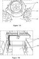
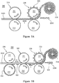
- Figures 1A and 1B show a conventional technology for producing lids.
- Figure 1A shows a punching machine for cutting out a punch slug according to a conventional technology, wherein the punching machine comprises a plurality of punches 110 and a die 130.
- the punching machine comprises a plurality of punches 110 and a die 130.
- Each of the punches 110 travels along a bore in the die 130 in a reciprocating motion, like a piston in an engine.
- a sheet of material is placed a surface of the die 130, as the punch 110 travels through an opening of the die 135, it applies a shear force the sheet of material, whereby it cuts out a punch slug from the sheet of material.
- This cut out punch slug is a cut out lid. So the shape of the opening of the die 135 and the punch 110 defines the shape and/or size of the cut out lid.
- Figure 1B shows an embossing machine for introducing embossing on a surface according to a conventional technology, wherein the embossing machine comprises a pair of rollers 150 with protrusions provided on surfaces thereof so that when a sheet of material 190 engages the surface, for example by being passed between the pair of the rollers 150, a surface of the sheet of material 190 deforms so that it has reciprocal depressions, i.e. the surface is embossed.
- a complex mechanical part such as a crankshaft and a camshaft for converting a rotational motion of the rollers 150 of the embossing machine into a reciprocating motion of the punches 110 are required to ensure a synchronised embossing and punching can take place to produce the lids.
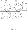
- Figure 2 shows an apparatus 200 for forming a lid 1050 from a sheet of a flexible material 1010 according to an embodiment of the present invention
- the apparatus 200 comprises an embosser 210 arranged to emboss a surface 1012 of the sheet 1010 of the flexible material, and a cutter 220 arranged to separate the lid 1050 from the sheet 1010 of the flexible material
- the cutter 220 comprises: a first cylinder 221 arranged to rotate about a first axis; a cutting die 225 provided on a surface of the first cylinder 221; and a second cylinder 222 arranged to engage the sheet 1010 of the flexible material so that the sheet 1010 engages the cutting die 225 on the first cylinder 221, whereby the cutting die 225 separates the lid 1050 from the sheet 1010 of the flexible material.
- the sheet 1010 of the flexible material can be made from any material suitable for forming a lid 1050, i.e. that can be embossed and cut to a certain shape.
- the flexible material comprises any one or more of: a metal such as an aluminium foil, a plastic/polymer film such as polypropylene (PP) or polyethylene terephthalate (PET), and a paper-based material such as a cardboard.
- the sheet 1010 is a polymer based film substrate, whereon a lid design is printed so that the separated, or cut out, lid 1050 forms a self-adhesive and/or monofoil label.
- the embosser 210 also comprises a first embossing cylinder 211 and a second embossing cylinder 212 arranged to engage the sheet 1010 of the flexible material so that the sheet 1010 engages embossing protrusions 215 on a surface of the first embossing cylinder 211.
- embossing protrusions may be provided on the second embossing cylinder 212 instead of, or in addition to, the embossing protrusions 215 on the first embossing cylinder 211 depending on which side and what type of embossing is desired for the sheet 1010.
- the first and/or the second embossing cylinder 211, 212 may be provided with embossing depressions so that when the sheet 1010 engages the embossing depressions, whereby the sheet 1010 is embossed.
- a cutting die is provided on a surface of the second cylinder 222 instead of, or in addition to, the cutting die 225 provided on the surface of the first cylinder 221 so that when the sheet 1010 engages the cutting die on the first and/or second cylinder 221, 222, the cutting die separates the lid 1050 from the sheet 1010.
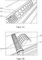
- Figure 3A and 3B show a cutting die 225 and a first cylinder 221 of the apparatus of Figure 2 according to an embodiment of the present invention.
- the cutting die 225 is detachably attached onto a surface of the first cylinder 221.
- At least parts 310 of the first cylinder 221 and the cutting die 225 are magnetic, and a magnetic force holds the cutting die 225 onto the surface of the first cylinder 221. So the magnetic first cylinder 221 and the magnetic cutting die 225 are used to separate, or cut out, the lids 1050 from the sheet 1010.
- the cutting die 225 comprises protrusions and/or depressions 229 which define the shape and size of the separated, or cut out, lids 1050.
- the cutting die 225 of the apparatus 200 of Figure 2 is replaceable with another cutting die. Therefore, cutting dies with different sets of protrusions and/or depressions for lids with different shapes and sizes can be manufactured, and used with the same first cylinder 221, that is the same apparatus 200 except the cutting die 225.
- the same cutting die 225 can also be used on a first cylinder of a different size, which can increase a range of sizes of the separated, or cut out, lids that can be formed using the apparatus 200 with the same cutting die 225.
- embosser 210 and the cutter 220 both of which uses rotary movement, means an assembly line like continuous flow processing of the sheet 1010 through the embossing and the cutting processes to form the lids 1050 is possible.
- the separated, or cut out, lids are heat sealed onto a container to seal an opening of the container.
- the container contains foodstuff and the lid, when heat sealed, prevents air from entering the container and spoiling the foodstuff.
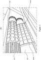
- Figure 4 shows the cutter 220 of Figure 2 comprising the cutting die 225 and the first cylinder 221 of Figure 3A and 3B .
- the cutter 220 operates by rotating the first cylinder 221 and the second cylinder 222 along a pair of parallel axis, with the cutting die 225 provided on a surface of the first cylinder 221 so that when a sheet 1010 of flexible material is fed between the first cylinder 221 and the second cylinder 222, the cutting die 225 engages a surface of the sheet 1010.
- the sheet 1010 comprises at least one lid 1055 printed thereon, and as the sheet 1010 passes through between the cutting die 225 (provided on the first cylinder 221) and the second cylinder 222 the printed at least one lid 1055 is aligned with the cutting die 225 so that each of the printed at least one lid 1055 can be separated by the cutting die 225 engaging the sheet 1010. That is, as the sheet 1010 passes through between the first cylinder 221 and the second cylinder 222, the sheet 1010 engages the cutting die 225 so that the cutting die 225 separates the at least one lid 1055 from the sheet 1010, to form the lid 1050 shown in Figure 2 .
- the cutter 220 is a rotary die cutting machine
- the first cylinder 221 is a tool holding cylinder for mounting the cutting die 225
- the second cylinder 222 is an anvil cylinder for allowing the cutting die 225 to exert a force onto a surface of the sheet 1010 of the flexible material to create a crease defining a boundary for each of the printed at least one lid 1055, whereby the crease enables separating of the lid 1050 from the sheet 1010.
- Figure 5A shows the apparatus 200 of Figure 2 further comprising a feeder 510 according to an embodiment of the present invention.
- the feeder 510 is arranged to feed the sheet 1010 of the flexible material to the embosser 210 and the cutter 220 at a predetermined speed, whereby a tension T on the sheet 1010 of the flexible material between the embosser 210 and the cutter 220 is maintained within a certain desirable range.
- the feeder 510 is arranged to pull the sheet 1010 of the flexible material at the predetermined speed to maintain the tension T within the certain desirable range.
- the certain desirable range for the tension T is determined depending on the characteristics of the flexible material, for example an elastic modulus, so that the sheet 1010 does not curl up as it passes through the embosser 210 or the cutter 220. Further, the effect of the thickness of the sheet 1010 on the effectiveness of the embossing by the embosser 210 and the cutting by the cutter 220 are also taken into account when determining the certain desirable range since larger tension T reduces the thickness of the sheet 1010 due to Poisson effect.
- the friction between the sheet 1010 and the engagement surfaces of the embosser 210 and the cutter 220 ensures the tension T remains within the certain desirable range. This is because the friction between the sheet 1010 and the outer surfaces of the first embossing cylinder 211, the second embossing cylinder 212, the cutting die 225 on the first cylinder 221, and the second cylinder 222 engaging the sheet 1010, introduces the tension T in the sheet 1010 as the sheet 1010 is pulled by the feeder 510.
- the apparatus 200 also compromises a sensor for detecting either or both of the speed of the sheet 1010 being pulled by the feeder 510 and the tension T, and a processor for adjusting the feeder 510 so that the tension T is maintained within the certain desirable range.
- a sensor for detecting either or both of the speed of the sheet 1010 being pulled by the feeder 510 and the tension T
- a processor for adjusting the feeder 510 so that the tension T is maintained within the certain desirable range.
- one or more further cylinders may be provided so that the sheet 1010 is pulled by the feeder 510 in a smoother manner, and also to adjust the fiction, and hence the tension T, experienced by the sheet 1010 as it passes through the apparatus 200 at the predetermined speed.
- Figure 5B shows the apparatus of Figure 5A further comprising a printer 530 according to an embodiment of the present invention.
- the printer 530 is arranged to print a shape and/or a colour 535 onto the sheet 1010 of the flexible material so that the cut out, or separated, lid 1050 has the desired shape and/or colour 535, i.e. a desired design, on a surface thereof.
- the printer 530 comprises a first printing cylinder 532 arranged to rotate about a first printing axis; a shape and/or a colour 535 provided on a surface of the first printing cylinder 532; and a second printing cylinder 531 arranged to engage the sheet 1010 of the flexible material so that the sheet 1010 engages the shape and/or the colour 535 on the first printing cylinder 532, whereby the shape and/or colour 535 is printed onto the sheet 1010, which in turn results in the cut out, or separated, lid 1050 with the shape and/or the colour 535 printed thereon.
- the printer 530 operates by rotating the first printing cylinder 532 and the second printing cylinder 531 along a pair of parallel axes, with the shape and/or colour 535 provided on a surface of the first printing cylinder 532 so that when the sheet 1010 of flexible material is fed between the first printing cylinder 532 and the second printing cylinder 531, the shape and/or the colour 535 engages a surface of the sheet 1010.
- the feeder 510 is arranged to feed the sheet 1010 of the flexible material to the embosser 210 and the cutter 220 at a predetermined speed, whereby a tension T on the sheet 1010 of the flexible material between the embosser 210 and the cutter 220, and a second tension T2 on the sheet 1010 between the printer 530 and the embosser 210 are maintained within a certain desirable range and a second certain desirable range respectively.
- the feeder 510 is arranged to pull the sheet 1010 of the flexible material at the predetermined speed to maintain the tension T within the certain desirable range, and the second tension T2 within the second certain desirable range.
- the second certain desirable range for the second tension T2 is also determined depending on the characteristics of the flexible material, for example an elastic modulus, so that the sheet 1010 does not curl up as it passes through the printer 530, the embosser 210 or the cutter 220. Further, the effect of the thickness of the sheet 1010 on the effectiveness of the printing by the printer 530, the embossing by the embosser 210 and the cutting by the cutter 220 are also taken into account when determining the second certain desirable range since larger second tension T2 reduces the thickness of the sheet 1010 due to Poisson effect.
- the tension T and the second tension T2 are equal. According to another embodiment, the tension T and the second tension T2 are not equal. It is understood that the values of the tension T and the second tension T2 will differ depending on different the frictional forces experienced by the sheet 1010 as it engages the surfaces of the printer 530, the embosser 210 and the cutter 220.
- the printer 530 is used after the embosser 210 but before the cutter 220, or even after the cutter 220 if the printer 530 is equipped with a lid detector for detecting a position of the separated, or cut off, lid 1050 for printing on a surface thereof.
- the printer 530 is used to print on the same surface of the sheet 1010 as the surface on which the embossing is introduced by the embosser 210, or the surface on which the cutting die 225 engages the sheet 1010.
- the printer 530 applies an ink on the surface of the sheet to print the shape and/or the colour 535, and the printer 530 further comprises a drier arranged to dry any previously applied ink so that subsequent printing of a second shape and/or a second colour can be applied to the sheet without merging into those previously printed.
- the drier may utilize hot air, infra-red or ultra-violet light depending on the ink used.
- the printer 530 may comprise a plurality of the first printing cylinder 532 and the second printing cylinder 531 pairing so that more than one layers of shapes and/or colours 535 can be applied to the sheet 1010 and the lid 1050 for a more complex design to be printed on the lid 1050.
- the printer 530 comprises a printing component that is not a rotary component, for example a linearly operated stamp, for applying the shapes and/or colours to the sheet 1010 and the lid 1050.
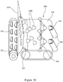
- Figure 5C shows a stacker 550 according an embodiment of the present invention.
- the stacker 550 is arranged to stack the lid 1050 separated from the sheet 1010 to form a stack 555 of lids 1050 separated from the sheet 1010.
- the stacker 550 comprises: a holder 556 arranged to hold a plurality of lids in at least one stack 555; a guide 552 arranged to guide lids 1050 separated from the sheet 1010 onto a conveyor 559; and a sorter 554 arranged to sort each lid 1050 on the conveyor 559 so that each lid 1050 is individually stacked onto one of the at least one stack 555.
- the sorter 554 also comprises a moving arm, an extremity of which rests on a surface of the conveyor 559, and moves along the surface of the conveyor 559 to separate each lid from another lid on the conveyor 559, whereby each lid is sorted and directed toward one of the at least one stack 555.
- the stack 555 of the plurality of lids is then stored in a holder 556.
- the lids in the holder 556 are then accessed so that the lids can be attached to a container, to be peeled away later to access the contents of the container.
- a processor such as a central processing unit
- a storage such as a memory
- a sensor such as a speed sensor, an accelerometer and/or a force sensor
- the processor and the memory are able to control the apparatus 200 or any component thereof using an output from the sensor.
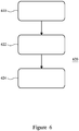
- Figure 6 shows a method for forming a lid from a sheet of a flexible material according to an embodiment of the present invention using the apparatus 200 of Figure 2 .
- the method comprises embossing a surface of the sheet of the flexible material 610 using an embosser, and separating the lid from the sheet of the flexible material 620 using a cutter.
- the separating 620 comprises: rotating a first cylinder of the cutter about a first axis 622; and engaging, by a second cylinder of the cutter, the sheet of the flexible material so that the sheet engages a cutting die provided on a surface of the first cylinder 624, whereby the cutting die separates the lid from the sheet of the flexible material.
- the separating 620 also comprises feeding, by a feeder, the sheet of the flexible material to the embosser and the cutter at a predetermined speed, whereby a tension on the sheet of the flexible material between the embosser and the cutter is maintained within a certain desirable range.
- the method further comprises a step of detecting, by a sensor, either or both of the speed of the sheet being pulled by the feeder and the tension on the sheet between the embosser and the cutter, and adjusting, by a processor, the feeder so that the tension is maintained within the certain desirable range.
- the method also further comprises a step of inputting, by a user via an input terminal, the speed at which the feeder pulls the sheet.
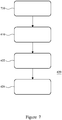
- Figure 7 shows the method of Figure 6 further comprising a step of attaching the cutting die onto the surface of the first cylinder 710 according to an embodiment of the present invention.
- the step of attaching 710 comprises placing the cutting die onto the surface of the first cylinder so that a magnetic force holds, or detachably attaches, the cutting die on the surface of the first cylinder.
- the method further comprises a step of printing a shape and/or a colour onto the sheet of the flexible material before the embossing 610.
- the step of printing a shape and/or a colour is performed after the embossing 610 but before the separating 620.
- the step of printing a shape and/or a colour is performed after the separating 620, and the method further comprises a step of detecting, by a lid detector, a position of a separated, or cut off, lid for printing on a surface thereof.
- the method further comprises a step of inputting operating parameters, such as the predetermined speed, the certain desirable range or the second certain desirable range, into the apparatus 200 using an input terminal.
- a sensor such as a speed sensor, an accelerometer and/or a force sensor
- the processor and the memory of the apparatus 200 are able to control the apparatus 200 or any component thereof using an output from the sensor as the input.
- Figure 8 shows the method of Figure 7 further comprising a step of stacking the lid separated from the sheet 810 according to an embodiment of the present invention.
- the step of stacking 810 uses a stacker to form a stack of lids separated from the sheet 810.
- the stacking 810 comprises: guiding, by a guide, lids separated from the sheet onto a conveyor; sorting, by a sorter, each lid on the conveyor so that each lid is individually stacked onto a stack from at least one stack; and holding or storing, by a holder, a plurality of lids in the at least one stack.
- the sorting also comprises moving an arm of the sorter, wherein an extremity of the arm rests on a surface of the conveyor and the movement of the arm along the surface of the conveyor separates, or distances, each lid from another lid on the conveyor. This sorts and directs each lid toward one of the at least one stack so that the plurality of lids are held, or stored, in the at least one stack held, or stored, in the holder.
- the lids in the holder 556 are then accessed so that the lids can be attached to a container, to be peeled away later to grant access to the contents of the container.
- the apparatus, or the method, for forming a lid from a sheet of a flexible material described herein enables the whole embossing, cutting, printing, and stacking processes to be performed in a continuous flow process manner. Further, by using a detachably attached cutting die in the cutting, the apparatus, or the method, enables flexible, replaceable and customisable use of the cutting die, resulting in cost and time efficient adapting of the apparatus for forming and producing lids of different shapes or sizes.
- embosser 210 a cutter 220, and a printer 530 described herein, all of which uses rotary movement, means it is possible to achieve an assembly line like continuous flow processing of the sheet 1010 through the embossing, the cutting and the printing processes to form the lids 1050, with a stacker 550 sorting and stacking the cut out, or separated, lids 1050 in a stack for storage.
- the lid 1050 may comprise any flexible material as long as the flexible material can be provided in a sheet 1010 form so that the sheet 1010 of the flexible material can be processed to form the lid 1050 using the apparatus and/or the method described herein, i.e. as long as the sheet 1010 can be embossed and cut to a certain shape or size.
Landscapes
- Engineering & Computer Science (AREA)
- Mechanical Engineering (AREA)
- Life Sciences & Earth Sciences (AREA)
- Forests & Forestry (AREA)
- Making Paper Articles (AREA)
- Perforating, Stamping-Out Or Severing By Means Other Than Cutting (AREA)
Abstract
Description
- The present invention concerns an apparatus or a method for forming a lid.
- Embodiments of the invention find particular, but not exclusive, use when forming a lid from a sheet of a flexible material using an embosser and a cutter.
- When producing a lid for closing a container, which can be at least partially peeled off the container to allow access to the inner chamber of the container, a number of steps are required to ensure the lid is fit for purpose.
- For example, as the lid is often produced and stored somewhere before it is attached to the container, a surface of the lid is often embossed so that when stored it does not get adhered to another lid. Therefore, an embossing machine is used to introduce embossing on the surface of the lid.
- Also, as an opening of the container, to be closed by the lid, may have different shapes and sizes, the lid needs to be cut into appropriate shapes and sizes for peel-ably closing the opening of the container. Therefore, a punching machine with a die having the required shapes and sizes is used to cut out punch slugs which are the lids.
- However, maintaining such a punching machine can be very costly. It is also difficult and expensive to produce lids of different shapes or sizes using such a punching machine. This is because both the punch and the die, i.e. essentially the whole punching machine, need to be re-machined to the required shapes or sizes, or be replaced with another punch or die with the required shapes or sizes.
- Further, often the embossing machines used for the lid production use rotary components whereas the punching machines require linearly moving components for the punching. This makes it difficult to drive both machines, and a complex system is needed for driving both machines in synchronisation to produce the lids in a continuous production or a continuous assembly process.
- Although not limited thereto, it is an aim of embodiments of the present invention to provide for an apparatus or a method for forming a lid from a sheet of a flexible material using an embosser and a cutter so that at least some of the difficulties and/or disadvantages discussed above are reduced.
- According to a first aspect of the invention, there is provided an apparatus for forming a lid from a sheet of a flexible material, the apparatus comprising an embosser arranged to emboss a surface of the sheet of the flexible material, and a cutter arranged to separate the lid from the sheet of the flexible material, wherein the cutter comprises: a first cylinder arranged to rotate about a first axis; a cutting die provided on a surface of the first cylinder; and a second cylinder arranged to engage the sheet of the flexible material so that the sheet engages the cutting die on the first cylinder, whereby the cutting die separates the lid from the sheet of the flexible material.
- Suitably, the cutting die is detachably attached onto the surface of the first cylinder.
- Suitably, at least parts of the first cylinder and the cutting die are magnetic, and a magnetic force holds the cutting die onto the surface of the first cylinder.
- Suitably, the cutter is a rotary die cutting machine, the first cylinder is a tool holding cylinder for mounting the cutting die and the second cylinder is an anvil cylinder for allowing the cutting die to exert a force on a surface of the sheet of the flexible material to create a crease for separating the lid.
- Suitably, the apparatus further comprises a feeder arranged to feed the sheet of the flexible material to the embosser and the cutter at a predetermined speed, whereby a tension on the sheet of the flexible material between the embosser and the cutter is maintained within a certain range.
- Suitably, the feeder is arranged to pull the sheet of the flexible material at the predetermined speed.
- Suitably, the apparatus further comprises a printer arranged to print onto the sheet of the flexible material.
- Suitably, the apparatus further comprises a stacker arranged to stack the lid separated from the sheet to form a stack of lids separated from the sheet.
- Suitably, the stacker comprises: a holder arranged to hold a plurality of lids in at least one stack; a guide arranged to guide lids separated from the sheet onto a conveyor; and a sorter arranged to sort each lid on the conveyor so that each lid is individually stacked onto one of the at least one stack.
- According to a second aspect of the invention, there is provided a method for forming a lid from a sheet of a flexible material, the method comprising embossing a surface of the sheet of the flexible material and separating the lid from the sheet of the flexible material, wherein the separating comprises: rotating a first cylinder about a first axis; and engaging, by a second cylinder, the sheet of the flexible material so that the sheet engages a cutting die provided on a surface of the first cylinder, whereby the cutting die separates the lid from the sheet of the flexible material.
- Suitably, the method further comprises a step of attaching the cutting die onto the surface of the first cylinder.
- Suitably, at least parts of the first cylinder and the cutting die are magnetic, and a magnetic force holds the cutting die onto the surface of the first cylinder.
- Suitably, the separating comprises feeding the sheet of the flexible material to an embosser and a cutter at a predetermined speed, whereby a tension on the sheet of the flexible material between the embosser and the cutter is maintained within a certain range.
- Suitably, the method further comprises a step of printing onto the sheet of the flexible material.
- Suitably, the method further comprises a step of stacking the lid separated from the sheet to form a stack of lids separated from the sheet.
- Suitably, the stacking comprises: guiding lids separated from the sheet onto a conveyor; sorting each lid on the conveyor so that each lid is individually stacked onto a stack from at least one stack; and holding a plurality of lids in the at least one stack.
- According to the present invention there is provided an apparatus and a method as set forth in the appended claims. Other features of the invention will be apparent from the dependent claims, and the description which follows.
- For a better understanding of the invention, and to show how embodiments of the same may be carried into effect, reference will now be made, by way of example, to the accompanying diagrammatic drawings in which:
-
Figure 1A shows a punching machine for cutting out a punch slug as a lid according to a conventional technology; -
Figure 1B shows an embossing machine for introducing embossing on a surface according to a conventional technology; -
Figure 2 shows an apparatus for forming a lid from a sheet of a flexible material according to an embodiment of the present invention; -
Figure 3A and 3B show a cutting die and a first cylinder of the apparatus ofFigure 2 according to an embodiment of the present invention; -
Figure 4 shows the cutter ofFigure 2 comprising the cutting die and the first cylinder ofFigure 3A and 3B according to an embodiment of the present invention; -
Figure 5A shows the apparatus ofFigure 2 further comprising a feeder according to an embodiment of the present invention; -
Figure 5B shows the apparatus ofFigure 5A further comprising a printer according to an embodiment of the present invention; -
Figure 5C shows a stacker according an embodiment of the present invention; -
Figure 6 shows a method for forming a lid from a sheet of a flexible material according to an embodiment of the present invention; -
Figure 7 shows the method ofFigure 6 further comprising a step of attaching according to an embodiment of the present invention; and -
Figure 8 shows the method ofFigure 7 further comprising a step of stacking according to an embodiment of the present invention. -
Figures 1A and 1B show a conventional technology for producing lids. - In particular,
Figure 1A shows a punching machine for cutting out a punch slug according to a conventional technology, wherein the punching machine comprises a plurality ofpunches 110 and adie 130. Each of thepunches 110 travels along a bore in thedie 130 in a reciprocating motion, like a piston in an engine. When a sheet of material is placed a surface of thedie 130, as thepunch 110 travels through an opening of thedie 135, it applies a shear force the sheet of material, whereby it cuts out a punch slug from the sheet of material. This cut out punch slug is a cut out lid. So the shape of the opening of thedie 135 and thepunch 110 defines the shape and/or size of the cut out lid. -
Figure 1B shows an embossing machine for introducing embossing on a surface according to a conventional technology, wherein the embossing machine comprises a pair ofrollers 150 with protrusions provided on surfaces thereof so that when a sheet ofmaterial 190 engages the surface, for example by being passed between the pair of therollers 150, a surface of the sheet ofmaterial 190 deforms so that it has reciprocal depressions, i.e. the surface is embossed. - When the lid production requires both embossing the sheet of
material 190 and then punching out the lids from the embossed sheet ofmaterial 190, a complex mechanical part such as a crankshaft and a camshaft for converting a rotational motion of therollers 150 of the embossing machine into a reciprocating motion of thepunches 110 are required to ensure a synchronised embossing and punching can take place to produce the lids. - However, maintaining such a punching machine can be very costly. It is also difficult and expensive to produce lids of different shapes or sizes using such a punching machine. This is because both the punch and the die, i.e. essentially the whole punching machine, need to be re-machined to the required shapes or sizes, or be replaced with another punch or die with the required shapes or sizes.
-
Figure 2 shows anapparatus 200 for forming alid 1050 from a sheet of aflexible material 1010 according to an embodiment of the present invention, wherein theapparatus 200 comprises anembosser 210 arranged to emboss asurface 1012 of thesheet 1010 of the flexible material, and acutter 220 arranged to separate thelid 1050 from thesheet 1010 of the flexible material, wherein thecutter 220 comprises: afirst cylinder 221 arranged to rotate about a first axis; acutting die 225 provided on a surface of thefirst cylinder 221; and asecond cylinder 222 arranged to engage thesheet 1010 of the flexible material so that thesheet 1010 engages thecutting die 225 on thefirst cylinder 221, whereby thecutting die 225 separates thelid 1050 from thesheet 1010 of the flexible material. - The
sheet 1010 of the flexible material can be made from any material suitable for forming alid 1050, i.e. that can be embossed and cut to a certain shape. For example the flexible material comprises any one or more of: a metal such as an aluminium foil, a plastic/polymer film such as polypropylene (PP) or polyethylene terephthalate (PET), and a paper-based material such as a cardboard. - Preferably, the
sheet 1010 is a polymer based film substrate, whereon a lid design is printed so that the separated, or cut out,lid 1050 forms a self-adhesive and/or monofoil label. - As shown in
Figure 2 , theembosser 210 also comprises afirst embossing cylinder 211 and a second embossingcylinder 212 arranged to engage thesheet 1010 of the flexible material so that thesheet 1010 engages embossingprotrusions 215 on a surface of thefirst embossing cylinder 211. - It is understood that according to another embodiment, embossing protrusions may be provided on the second embossing
cylinder 212 instead of, or in addition to, theembossing protrusions 215 on thefirst embossing cylinder 211 depending on which side and what type of embossing is desired for thesheet 1010. Further, according to another embodiment, the first and/or thesecond embossing cylinder sheet 1010 engages the embossing depressions, whereby thesheet 1010 is embossed. - It is also understood that according to an embodiment, a cutting die is provided on a surface of the
second cylinder 222 instead of, or in addition to, the cutting die 225 provided on the surface of thefirst cylinder 221 so that when thesheet 1010 engages the cutting die on the first and/orsecond cylinder lid 1050 from thesheet 1010. -
Figure 3A and 3B show acutting die 225 and afirst cylinder 221 of the apparatus ofFigure 2 according to an embodiment of the present invention. The cutting die 225 is detachably attached onto a surface of thefirst cylinder 221. Atleast parts 310 of thefirst cylinder 221 and the cutting die 225 are magnetic, and a magnetic force holds the cutting die 225 onto the surface of thefirst cylinder 221. So the magneticfirst cylinder 221 and the magnetic cutting die 225 are used to separate, or cut out, thelids 1050 from thesheet 1010. - The cutting die 225 comprises protrusions and/or
depressions 229 which define the shape and size of the separated, or cut out, lids 1050. As the cutting die 225 is detachable from the surface of thefirst cylinder 221, the cutting die 225 of theapparatus 200 ofFigure 2 is replaceable with another cutting die. Therefore, cutting dies with different sets of protrusions and/or depressions for lids with different shapes and sizes can be manufactured, and used with the samefirst cylinder 221, that is thesame apparatus 200 except the cutting die 225. - Further, if the cutting die 225 is also made from a flexible material, the same cutting die 225 can also be used on a first cylinder of a different size, which can increase a range of sizes of the separated, or cut out, lids that can be formed using the
apparatus 200 with the same cutting die 225. - This is advantageous because this flexibility, replaceability and customisability of the cutting die and the first cylinder combination enables cost and time efficient adapting of the
apparatus 200 for forming and producing the lids. As only the cutting die 225 or thefirst cylinder 221, which are both easily detachable from theapparatus 200, needs to be adapted to produce lids of a different shape or size, the cost and time involved in enabling theapparatus 200 to produce such lids of a different shape or size is much cheaper and shorter than adapting a conventional punching machine to do the same. - In addition, use of the
embosser 210 and thecutter 220, both of which uses rotary movement, means an assembly line like continuous flow processing of thesheet 1010 through the embossing and the cutting processes to form thelids 1050 is possible. This means there is less need for a complex mechanical part such as a crankshaft and a camshaft used in the conventional embossing machine and the conventional punching machine combination, which in turn means less maintenance costs from any potential reliability and maintenance issues arising form the complex mechanical parts. - Although not shown, according to an embodiment the separated, or cut out, lids are heat sealed onto a container to seal an opening of the container. The container contains foodstuff and the lid, when heat sealed, prevents air from entering the container and spoiling the foodstuff.
-
Figure 4 shows thecutter 220 ofFigure 2 comprising the cutting die 225 and thefirst cylinder 221 ofFigure 3A and 3B . Thecutter 220 operates by rotating thefirst cylinder 221 and thesecond cylinder 222 along a pair of parallel axis, with the cutting die 225 provided on a surface of thefirst cylinder 221 so that when asheet 1010 of flexible material is fed between thefirst cylinder 221 and thesecond cylinder 222, the cutting die 225 engages a surface of thesheet 1010. - The
sheet 1010 comprises at least onelid 1055 printed thereon, and as thesheet 1010 passes through between the cutting die 225 (provided on the first cylinder 221) and thesecond cylinder 222 the printed at least onelid 1055 is aligned with the cutting die 225 so that each of the printed at least onelid 1055 can be separated by the cutting die 225 engaging thesheet 1010. That is, as thesheet 1010 passes through between thefirst cylinder 221 and thesecond cylinder 222, thesheet 1010 engages the cutting die 225 so that the cutting die 225 separates the at least onelid 1055 from thesheet 1010, to form thelid 1050 shown inFigure 2 . - For example, the
cutter 220 is a rotary die cutting machine, thefirst cylinder 221 is a tool holding cylinder for mounting the cutting die 225, and thesecond cylinder 222 is an anvil cylinder for allowing the cutting die 225 to exert a force onto a surface of thesheet 1010 of the flexible material to create a crease defining a boundary for each of the printed at least onelid 1055, whereby the crease enables separating of thelid 1050 from thesheet 1010. -
Figure 5A shows theapparatus 200 ofFigure 2 further comprising afeeder 510 according to an embodiment of the present invention. - The
feeder 510 is arranged to feed thesheet 1010 of the flexible material to theembosser 210 and thecutter 220 at a predetermined speed, whereby a tension T on thesheet 1010 of the flexible material between theembosser 210 and thecutter 220 is maintained within a certain desirable range. Thefeeder 510 is arranged to pull thesheet 1010 of the flexible material at the predetermined speed to maintain the tension T within the certain desirable range. - The certain desirable range for the tension T is determined depending on the characteristics of the flexible material, for example an elastic modulus, so that the
sheet 1010 does not curl up as it passes through theembosser 210 or thecutter 220. Further, the effect of the thickness of thesheet 1010 on the effectiveness of the embossing by theembosser 210 and the cutting by thecutter 220 are also taken into account when determining the certain desirable range since larger tension T reduces the thickness of thesheet 1010 due to Poisson effect. - As the
feeder 510 pulls thesheet 1010 at the predetermined speed, which can also be a range of predetermined speeds calculated for maintaining the tension T within the certain desired range, the friction between thesheet 1010 and the engagement surfaces of theembosser 210 and thecutter 220 ensures the tension T remains within the certain desirable range. This is because the friction between thesheet 1010 and the outer surfaces of thefirst embossing cylinder 211, thesecond embossing cylinder 212, the cutting die 225 on thefirst cylinder 221, and thesecond cylinder 222 engaging thesheet 1010, introduces the tension T in thesheet 1010 as thesheet 1010 is pulled by thefeeder 510. - According to an embodiment the
apparatus 200 also compromises a sensor for detecting either or both of the speed of thesheet 1010 being pulled by thefeeder 510 and the tension T, and a processor for adjusting thefeeder 510 so that the tension T is maintained within the certain desirable range. Further, one or more further cylinders may be provided so that thesheet 1010 is pulled by thefeeder 510 in a smoother manner, and also to adjust the fiction, and hence the tension T, experienced by thesheet 1010 as it passes through theapparatus 200 at the predetermined speed. -
Figure 5B shows the apparatus ofFigure 5A further comprising aprinter 530 according to an embodiment of the present invention. - The
printer 530 is arranged to print a shape and/or acolour 535 onto thesheet 1010 of the flexible material so that the cut out, or separated,lid 1050 has the desired shape and/orcolour 535, i.e. a desired design, on a surface thereof. - The
printer 530 comprises afirst printing cylinder 532 arranged to rotate about a first printing axis; a shape and/or acolour 535 provided on a surface of thefirst printing cylinder 532; and asecond printing cylinder 531 arranged to engage thesheet 1010 of the flexible material so that thesheet 1010 engages the shape and/or thecolour 535 on thefirst printing cylinder 532, whereby the shape and/orcolour 535 is printed onto thesheet 1010, which in turn results in the cut out, or separated,lid 1050 with the shape and/or thecolour 535 printed thereon. Theprinter 530 operates by rotating thefirst printing cylinder 532 and thesecond printing cylinder 531 along a pair of parallel axes, with the shape and/orcolour 535 provided on a surface of thefirst printing cylinder 532 so that when thesheet 1010 of flexible material is fed between thefirst printing cylinder 532 and thesecond printing cylinder 531, the shape and/or thecolour 535 engages a surface of thesheet 1010. - When the
printer 530 is used, thefeeder 510 is arranged to feed thesheet 1010 of the flexible material to theembosser 210 and thecutter 220 at a predetermined speed, whereby a tension T on thesheet 1010 of the flexible material between theembosser 210 and thecutter 220, and a second tension T2 on thesheet 1010 between theprinter 530 and theembosser 210 are maintained within a certain desirable range and a second certain desirable range respectively. Thefeeder 510 is arranged to pull thesheet 1010 of the flexible material at the predetermined speed to maintain the tension T within the certain desirable range, and the second tension T2 within the second certain desirable range. - The second certain desirable range for the second tension T2 is also determined depending on the characteristics of the flexible material, for example an elastic modulus, so that the
sheet 1010 does not curl up as it passes through theprinter 530, theembosser 210 or thecutter 220. Further, the effect of the thickness of thesheet 1010 on the effectiveness of the printing by theprinter 530, the embossing by theembosser 210 and the cutting by thecutter 220 are also taken into account when determining the second certain desirable range since larger second tension T2 reduces the thickness of thesheet 1010 due to Poisson effect. - According to an embodiment, the tension T and the second tension T2 are equal. According to another embodiment, the tension T and the second tension T2 are not equal. It is understood that the values of the tension T and the second tension T2 will differ depending on different the frictional forces experienced by the
sheet 1010 as it engages the surfaces of theprinter 530, theembosser 210 and thecutter 220. - It is also understood that according to another embodiment, the
printer 530 is used after theembosser 210 but before thecutter 220, or even after thecutter 220 if theprinter 530 is equipped with a lid detector for detecting a position of the separated, or cut off,lid 1050 for printing on a surface thereof. - It is also understood that according to another embodiment, the
printer 530 is used to print on the same surface of thesheet 1010 as the surface on which the embossing is introduced by theembosser 210, or the surface on which the cutting die 225 engages thesheet 1010. - According to an embodiment, the
printer 530 applies an ink on the surface of the sheet to print the shape and/or thecolour 535, and theprinter 530 further comprises a drier arranged to dry any previously applied ink so that subsequent printing of a second shape and/or a second colour can be applied to the sheet without merging into those previously printed. The drier may utilize hot air, infra-red or ultra-violet light depending on the ink used. - It is understood that the
printer 530 may comprise a plurality of thefirst printing cylinder 532 and thesecond printing cylinder 531 pairing so that more than one layers of shapes and/orcolours 535 can be applied to thesheet 1010 and thelid 1050 for a more complex design to be printed on thelid 1050. - According to another embodiment, the
printer 530 comprises a printing component that is not a rotary component, for example a linearly operated stamp, for applying the shapes and/or colours to thesheet 1010 and thelid 1050. -
Figure 5C shows astacker 550 according an embodiment of the present invention. - The
stacker 550 is arranged to stack thelid 1050 separated from thesheet 1010 to form astack 555 oflids 1050 separated from thesheet 1010. Thestacker 550 comprises: aholder 556 arranged to hold a plurality of lids in at least onestack 555; aguide 552 arranged to guidelids 1050 separated from thesheet 1010 onto aconveyor 559; and asorter 554 arranged to sort eachlid 1050 on theconveyor 559 so that eachlid 1050 is individually stacked onto one of the at least onestack 555. - The
sorter 554 also comprises a moving arm, an extremity of which rests on a surface of theconveyor 559, and moves along the surface of theconveyor 559 to separate each lid from another lid on theconveyor 559, whereby each lid is sorted and directed toward one of the at least onestack 555. Thestack 555 of the plurality of lids is then stored in aholder 556. - The lids in the
holder 556 are then accessed so that the lids can be attached to a container, to be peeled away later to access the contents of the container. - It is understood that, although not shown, a processor (such as a central processing unit) and a storage (such as a memory) are provided with the
apparatus 200 to process and store instructions for controlling theapparatus 200, for example for controlling any one or more of theembosser 210, thecutter 220, the feeder, theprinter 530, and thestacker 550. An input terminal for inputting operating parameters, such as the predetermined speed, the certain desirable range or the second certain desirable range, can also be provided with theapparatus 200. Further, a sensor (such as a speed sensor, an accelerometer and/or a force sensor) may also be provided so that the processor and the memory are able to control theapparatus 200 or any component thereof using an output from the sensor. -
Figure 6 shows a method for forming a lid from a sheet of a flexible material according to an embodiment of the present invention using theapparatus 200 ofFigure 2 . - The method comprises embossing a surface of the sheet of the
flexible material 610 using an embosser, and separating the lid from the sheet of theflexible material 620 using a cutter. The separating 620 comprises: rotating a first cylinder of the cutter about afirst axis 622; and engaging, by a second cylinder of the cutter, the sheet of the flexible material so that the sheet engages a cutting die provided on a surface of thefirst cylinder 624, whereby the cutting die separates the lid from the sheet of the flexible material. - According to an embodiment, the separating 620 also comprises feeding, by a feeder, the sheet of the flexible material to the embosser and the cutter at a predetermined speed, whereby a tension on the sheet of the flexible material between the embosser and the cutter is maintained within a certain desirable range.
- When the feeder is used, the method further comprises a step of detecting, by a sensor, either or both of the speed of the sheet being pulled by the feeder and the tension on the sheet between the embosser and the cutter, and adjusting, by a processor, the feeder so that the tension is maintained within the certain desirable range.
- Alternatively or additionally, the method also further comprises a step of inputting, by a user via an input terminal, the speed at which the feeder pulls the sheet.
-
Figure 7 shows the method ofFigure 6 further comprising a step of attaching the cutting die onto the surface of thefirst cylinder 710 according to an embodiment of the present invention. When at least parts of the first cylinder and the cutting die are magnetic, the step of attaching 710 comprises placing the cutting die onto the surface of the first cylinder so that a magnetic force holds, or detachably attaches, the cutting die on the surface of the first cylinder. - It is understood that according to another embodiment, other means of detachably attaching the cutting die onto the surface of the first cylinder may be used, for example using a temporary adhesive or a locking mechanism.
- According to an embodiment, the method further comprises a step of printing a shape and/or a colour onto the sheet of the flexible material before the
embossing 610. According to another embodiment, the step of printing a shape and/or a colour is performed after theembossing 610 but before the separating 620. According to yet another embodiment, the step of printing a shape and/or a colour is performed after the separating 620, and the method further comprises a step of detecting, by a lid detector, a position of a separated, or cut off, lid for printing on a surface thereof. - According to an embodiment, the method further comprises a step of inputting operating parameters, such as the predetermined speed, the certain desirable range or the second certain desirable range, into the
apparatus 200 using an input terminal. A sensor (such as a speed sensor, an accelerometer and/or a force sensor) may also be provided so that the processor and the memory of theapparatus 200 are able to control theapparatus 200 or any component thereof using an output from the sensor as the input. -
Figure 8 shows the method ofFigure 7 further comprising a step of stacking the lid separated from thesheet 810 according to an embodiment of the present invention. - The step of stacking 810 uses a stacker to form a stack of lids separated from the
sheet 810. The stacking 810 comprises: guiding, by a guide, lids separated from the sheet onto a conveyor; sorting, by a sorter, each lid on the conveyor so that each lid is individually stacked onto a stack from at least one stack; and holding or storing, by a holder, a plurality of lids in the at least one stack. - According to an embodiment, the sorting also comprises moving an arm of the sorter, wherein an extremity of the arm rests on a surface of the conveyor and the movement of the arm along the surface of the conveyor separates, or distances, each lid from another lid on the conveyor. This sorts and directs each lid toward one of the at least one stack so that the plurality of lids are held, or stored, in the at least one stack held, or stored, in the holder.
- The lids in the
holder 556 are then accessed so that the lids can be attached to a container, to be peeled away later to grant access to the contents of the container. - The apparatus, or the method, for forming a lid from a sheet of a flexible material described herein enables the whole embossing, cutting, printing, and stacking processes to be performed in a continuous flow process manner. Further, by using a detachably attached cutting die in the cutting, the apparatus, or the method, enables flexible, replaceable and customisable use of the cutting die, resulting in cost and time efficient adapting of the apparatus for forming and producing lids of different shapes or sizes.
- In addition, use of an
embosser 210, acutter 220, and aprinter 530 described herein, all of which uses rotary movement, means it is possible to achieve an assembly line like continuous flow processing of thesheet 1010 through the embossing, the cutting and the printing processes to form thelids 1050, with astacker 550 sorting and stacking the cut out, or separated,lids 1050 in a stack for storage. - It is understood that according to an embodiment of the present invention, the
lid 1050 may comprise any flexible material as long as the flexible material can be provided in asheet 1010 form so that thesheet 1010 of the flexible material can be processed to form thelid 1050 using the apparatus and/or the method described herein, i.e. as long as thesheet 1010 can be embossed and cut to a certain shape or size. - Although a few preferred embodiments have been shown and described, it will be appreciated by those skilled in the art that various changes and modifications might be made without departing from the scope of the invention, as defined in the appended claims.
- Attention is directed to all papers and documents which are filed concurrently with or previous to this specification in connection with this application and which are open to public inspection with this specification, and the contents of all such papers and documents are incorporated herein by reference.
- All of the features disclosed in this specification (including any accompanying claims, abstract and drawings), and/or all of the steps of any method or process so disclosed, may be combined in any combination, except combinations where at least some of such features and/or steps are mutually exclusive.
- Each feature disclosed in this specification (including any accompanying claims, abstract and drawings) may be replaced by alternative features serving the same, equivalent or similar purpose, unless expressly stated otherwise. Thus, unless expressly stated otherwise, each feature disclosed is one example only of a generic series of equivalent or similar features.
- The invention is not restricted to the details of the foregoing embodiment(s). The invention extends to any novel one, or any novel combination, of the features disclosed in this specification (including any accompanying claims, abstract and drawings), or to any novel one, or any novel combination, of the steps of any method or process so disclosed.
Claims (17)
- An apparatus for forming a lid from a sheet of a flexible material, the apparatus comprising an embosser arranged to emboss a surface of the sheet of the flexible material, and a cutter arranged to separate the lid from the sheet of the flexible material, wherein the cutter comprises:a first cylinder arranged to rotate about a first axis;a cutting die provided on a surface of the first cylinder; anda second cylinder arranged to engage the sheet of the flexible material so that the sheet engages the cutting die on the first cylinder, whereby the cutting die separates the lid from the sheet of the flexible material.
- The apparatus of claim 1, wherein the cutting die is detachably attached onto the surface of the first cylinder.
- The apparatus of claim 2, wherein at least parts of the first cylinder and the cutting die are magnetic, and a magnetic force holds the cutting die onto the surface of the first cylinder.
- The apparatus of any preceding claim, wherein the cutter is a rotary die cutting machine, the first cylinder is a tool holding cylinder for mounting the cutting die and the second cylinder is an anvil cylinder for allowing the cutting die to exert a force on a surface of the sheet of the flexible material to create a crease for separating the lid.
- The apparatus of any preceding claim further comprising a feeder arranged to feed the sheet of the flexible material to the embosser and the cutter at a predetermined speed, whereby a tension on the sheet of the flexible material between the embosser and the cutter is maintained within a certain range.
- The apparatus of claim 5, wherein the feeder is arranged to pull the sheet of the flexible material at the predetermined speed.
- The apparatus of any preceding claim further comprising a printer arranged to print onto the sheet of the flexible material.
- The apparatus of any preceding claim further comprising a stacker arranged to stack the lid separated from the sheet to form a stack of lids separated from the sheet.
- The apparatus of claim 8, wherein the stacker comprises:a holder arranged to hold a plurality of lids in at least one stack;a guide arranged to guide lids separated from the sheet onto a conveyor; anda sorter arranged to sort each lid on the conveyor so that each lid is individually stacked onto one of the at least one stack.
- A method for forming a lid from a sheet of a flexible material, the method comprising embossing a surface of the sheet of the flexible material and separating the lid from the sheet of the flexible material, wherein the separating comprises:rotating a first cylinder about a first axis; andengaging, by a second cylinder, the sheet of the flexible material so that the sheet engages a cutting die provided on a surface of the first cylinder,whereby the cutting die separates the lid from the sheet of the flexible material.
- The method of claim 10 further comprising a step of attaching the cutting die onto the surface of the first cylinder.
- The method of claim 11, wherein at least parts of the first cylinder and the cutting die are magnetic, and a magnetic force holds the cutting die onto the surface of the first cylinder.
- The method of any one of claims 10 to 12, wherein the separating comprises feeding the sheet of the flexible material to an embosser and a cutter at a predetermined speed, whereby a tension on the sheet of the flexible material between the embosser and the cutter is maintained within a certain range.
- The method of any one of claims 10 to 13 further comprising a step of printing onto the sheet of the flexible material.
- The method of any one of claims 10 to 14, further comprising a step of stacking the lid separated from the sheet to form a stack of lids separated from the sheet.
- The method of claim 15, wherein the stacking comprises:guiding lids separated from the sheet onto a conveyor;sorting each lid on the conveyor so that each lid is individually stacked onto a stack from at least one stack; andholding a plurality of lids in the at least one stack.
- An apparatus or a method as described herein, with reference to the accompanying drawings.
Applications Claiming Priority (1)
| Application Number | Priority Date | Filing Date | Title |
|---|---|---|---|
| GB1607888.3A GB2549979A (en) | 2016-05-05 | 2016-05-05 | Improvements in and relating to production of lids |
Publications (2)
| Publication Number | Publication Date |
|---|---|
| EP3243618A2 true EP3243618A2 (en) | 2017-11-15 |
| EP3243618A3 EP3243618A3 (en) | 2018-04-04 |
Family
ID=56297222
Family Applications (1)
| Application Number | Title | Priority Date | Filing Date |
|---|---|---|---|
| EP17169243.7A Withdrawn EP3243618A3 (en) | 2016-05-05 | 2017-05-03 | Improvements in and relating to production of lids |
Country Status (2)
| Country | Link |
|---|---|
| EP (1) | EP3243618A3 (en) |
| GB (1) | GB2549979A (en) |
Families Citing this family (1)
| Publication number | Priority date | Publication date | Assignee | Title |
|---|---|---|---|---|
| CN109015828A (en) * | 2018-08-31 | 2018-12-18 | 嘉兴合力蜂窝制品有限公司 | A kind of longitudinal sectional marking press of cardboard |
Family Cites Families (9)
| Publication number | Priority date | Publication date | Assignee | Title |
|---|---|---|---|---|
| DE3500547A1 (en) * | 1985-01-10 | 1986-07-10 | Focke & Co (GmbH & Co), 2810 Verden | METHOD AND DEVICE FOR PRODUCING CUT-OUTS FOR PACKAGING |
| DE4102005A1 (en) * | 1991-01-24 | 1992-07-30 | Focke & Co | METHOD AND DEVICE FOR PRODUCING FOLDING BOXES WITH A COLLAR |
| GB9321148D0 (en) * | 1993-10-13 | 1993-12-01 | Molins Plc | Package blank feeding |
| DE19726324A1 (en) * | 1997-06-20 | 1998-12-24 | Focke & Co | Method and device for manufacturing hinged boxes |
| SE516978C2 (en) * | 1998-04-07 | 2002-03-26 | Tetra Laval Holdings & Finance | Ways to manufacture big-line packaged material |
| US20050042414A1 (en) * | 2003-08-19 | 2005-02-24 | Malay Jeffrey J. | Methods of making sealing members for induction sealing of containers |
| US7051632B2 (en) * | 2003-09-03 | 2006-05-30 | Paper Benders Supply, Inc. | Magnetic rotary die |
| BRPI0418657A (en) * | 2004-03-18 | 2007-05-29 | Sca Hygiene Prod Ab | method and device for producing a multilayer blanket of flexible material, such as paper and nonwoven, and multilayer material produced by the method |
| ES2326336T5 (en) * | 2006-06-28 | 2014-11-20 | Amcor Flexibles Kreuzlingen Ag | Procedure for the production of embossed lid elements for containers and lid elements for containers |
-
2016
- 2016-05-05 GB GB1607888.3A patent/GB2549979A/en not_active Withdrawn
-
2017
- 2017-05-03 EP EP17169243.7A patent/EP3243618A3/en not_active Withdrawn
Also Published As
| Publication number | Publication date |
|---|---|
| GB201607888D0 (en) | 2016-06-22 |
| GB2549979A (en) | 2017-11-08 |
| EP3243618A3 (en) | 2018-04-04 |
Similar Documents
| Publication | Publication Date | Title |
|---|---|---|
| TWI607930B (en) | Unit for converting a continuous web substrate, and packaging production machine thus equipped | |
| JP2008030952A (en) | Rear edge braking device | |
| JP2006305903A (en) | Printing machine | |
| JP2008100343A (en) | Flat base type sheet punching machine | |
| US10336567B2 (en) | Manufacturing system with flat-bed and rotary diecutters and method for operating the manufacturing system | |
| JP2005263494A (en) | Paper feeder for punching device or stamping press | |
| US20170361952A1 (en) | Method and device for producing partially embossed blanks | |
| WO2020203973A1 (en) | Dimensionally-variable box blank manufacturing device, dimensionally-variable box blank manufacturing method, box blank assembling method, and dimensionally-variable automatic packaging line | |
| EP1165418B1 (en) | Sheet material processing | |
| ITBO20100662A1 (en) | TAPE MACHINE | |
| EP3243618A2 (en) | Improvements in and relating to production of lids | |
| EP3271120B1 (en) | Method and apparatus for producing a container carrier | |
| EP2857187B1 (en) | Device and method for producing embossed cover elements for packaging | |
| US11597200B2 (en) | Sheet processing machine, method for inspecting at least one remaining portion of at least one sheet processed by a shaping device, and method for inspecting a sheet | |
| US3937452A (en) | Method and apparatus for manufacturing continuous form sets | |
| US5183247A (en) | Method of, and apparatus for, detecting the position of a marking or separating element in a stack of substantially flat products | |
| US11685133B2 (en) | Digital systems and processes for cutting and creasing corrugated cardboards | |
| CN110520265B (en) | Perforating machine and method for perforating flat film tubes | |
| US11814254B2 (en) | Die-cutting machine comprising a transport system configured as a chain gripper system and method for opening at least one holding element | |
| US11485035B2 (en) | Sheet processing machine and method for driving at least one tool of a sheet processing machine | |
| CN100433077C (en) | Label mfg device and mfg method | |
| KR102640746B1 (en) | Label punching device and method of operating the same | |
| EP3148723B1 (en) | Multi-punch press | |
| RU188772U1 (en) | Platinky roll | |
| RU2258007C2 (en) | Variable folder |
Legal Events
| Date | Code | Title | Description |
|---|---|---|---|
| PUAI | Public reference made under article 153(3) epc to a published international application that has entered the european phase |
Free format text: ORIGINAL CODE: 0009012 |
|
| STAA | Information on the status of an ep patent application or granted ep patent |
Free format text: STATUS: THE APPLICATION HAS BEEN PUBLISHED |
|
| AK | Designated contracting states |
Kind code of ref document: A2 Designated state(s): AL AT BE BG CH CY CZ DE DK EE ES FI FR GB GR HR HU IE IS IT LI LT LU LV MC MK MT NL NO PL PT RO RS SE SI SK SM TR |
|
| AX | Request for extension of the european patent |
Extension state: BA ME |
|
| PUAL | Search report despatched |
Free format text: ORIGINAL CODE: 0009013 |
|
| AK | Designated contracting states |
Kind code of ref document: A3 Designated state(s): AL AT BE BG CH CY CZ DE DK EE ES FI FR GB GR HR HU IE IS IT LI LT LU LV MC MK MT NL NO PL PT RO RS SE SI SK SM TR |
|
| AX | Request for extension of the european patent |
Extension state: BA ME |
|
| RIC1 | Information provided on ipc code assigned before grant |
Ipc: B26D 7/32 20060101ALI20180228BHEP Ipc: B26F 1/44 20060101ALI20180228BHEP Ipc: B31F 1/07 20060101ALI20180228BHEP Ipc: B26F 1/38 20060101AFI20180228BHEP |
|
| STAA | Information on the status of an ep patent application or granted ep patent |
Free format text: STATUS: REQUEST FOR EXAMINATION WAS MADE |
|
| 17P | Request for examination filed |
Effective date: 20181004 |
|
| RBV | Designated contracting states (corrected) |
Designated state(s): AL AT BE BG CH CY CZ DE DK EE ES FI FR GB GR HR HU IE IS IT LI LT LU LV MC MK MT NL NO PL PT RO RS SE SI SK SM TR |
|
| STAA | Information on the status of an ep patent application or granted ep patent |
Free format text: STATUS: THE APPLICATION IS DEEMED TO BE WITHDRAWN |
|
| 18D | Application deemed to be withdrawn |
Effective date: 20191203 |