EP3243614B1 - A cutting unit for a labelling machine - Google Patents
A cutting unit for a labelling machine Download PDFInfo
- Publication number
- EP3243614B1 EP3243614B1 EP16305535.3A EP16305535A EP3243614B1 EP 3243614 B1 EP3243614 B1 EP 3243614B1 EP 16305535 A EP16305535 A EP 16305535A EP 3243614 B1 EP3243614 B1 EP 3243614B1
- Authority
- EP
- European Patent Office
- Prior art keywords
- stationary blade
- cutting
- blade
- web
- rotary
- Prior art date
- Legal status (The legal status is an assumption and is not a legal conclusion. Google has not performed a legal analysis and makes no representation as to the accuracy of the status listed.)
- Active
Links
Images


Classifications
-
- B—PERFORMING OPERATIONS; TRANSPORTING
- B26—HAND CUTTING TOOLS; CUTTING; SEVERING
- B26D—CUTTING; DETAILS COMMON TO MACHINES FOR PERFORATING, PUNCHING, CUTTING-OUT, STAMPING-OUT OR SEVERING
- B26D1/00—Cutting through work characterised by the nature or movement of the cutting member or particular materials not otherwise provided for; Apparatus or machines therefor; Cutting members therefor
- B26D1/01—Cutting through work characterised by the nature or movement of the cutting member or particular materials not otherwise provided for; Apparatus or machines therefor; Cutting members therefor involving a cutting member which does not travel with the work
- B26D1/12—Cutting through work characterised by the nature or movement of the cutting member or particular materials not otherwise provided for; Apparatus or machines therefor; Cutting members therefor involving a cutting member which does not travel with the work having a cutting member moving about an axis
- B26D1/25—Cutting through work characterised by the nature or movement of the cutting member or particular materials not otherwise provided for; Apparatus or machines therefor; Cutting members therefor involving a cutting member which does not travel with the work having a cutting member moving about an axis with a non-circular cutting member
- B26D1/34—Cutting through work characterised by the nature or movement of the cutting member or particular materials not otherwise provided for; Apparatus or machines therefor; Cutting members therefor involving a cutting member which does not travel with the work having a cutting member moving about an axis with a non-circular cutting member moving about an axis parallel to the line of cut
- B26D1/38—Cutting through work characterised by the nature or movement of the cutting member or particular materials not otherwise provided for; Apparatus or machines therefor; Cutting members therefor involving a cutting member which does not travel with the work having a cutting member moving about an axis with a non-circular cutting member moving about an axis parallel to the line of cut and coacting with a fixed blade or other fixed member
- B26D1/385—Cutting through work characterised by the nature or movement of the cutting member or particular materials not otherwise provided for; Apparatus or machines therefor; Cutting members therefor involving a cutting member which does not travel with the work having a cutting member moving about an axis with a non-circular cutting member moving about an axis parallel to the line of cut and coacting with a fixed blade or other fixed member for thin material, e.g. for sheets, strips or the like
-
- B—PERFORMING OPERATIONS; TRANSPORTING
- B26—HAND CUTTING TOOLS; CUTTING; SEVERING
- B26D—CUTTING; DETAILS COMMON TO MACHINES FOR PERFORATING, PUNCHING, CUTTING-OUT, STAMPING-OUT OR SEVERING
- B26D7/00—Details of apparatus for cutting, cutting-out, stamping-out, punching, perforating, or severing by means other than cutting
- B26D7/26—Means for mounting or adjusting the cutting member; Means for adjusting the stroke of the cutting member
- B26D7/2628—Means for adjusting the position of the cutting member
Landscapes
- Life Sciences & Earth Sciences (AREA)
- Forests & Forestry (AREA)
- Engineering & Computer Science (AREA)
- Mechanical Engineering (AREA)
- Details Of Cutting Devices (AREA)
- Treatment Of Fiber Materials (AREA)
Description
- The present invention relates to a cutting unit for labelling machines, particularly for the type of labelling machines comprising a reel from which a web of labelling material is cut into lengths (labels) of a predetermined size and applied on articles, namely on containers filled with a pourable product.
- Known labelling machines of the above-mentioned type basically comprise a carousel for advancing the articles along an article path towards a labelling station, and a labelling unit fed with a web of labelling material, progressively advancing such web along a label path towards the labelling station as well as cutting the web itself into a plurality of labels to be applied onto the articles moving along the article path.
- In detail, the labelling unit comprises:
- one or more motorized feeding rolls for moving the web of labelling material from a label reel towards the carousel;
- a cutting unit for cutting one label at any one time from the web; and
- a vacuum drum receiving the cut labels and transferring them to the articles in the carousel.
- As each label is transferred from the cutting unit toward the labelling station, a layer of adhesive is typically applied on its surface for subsequently securing it to the surface of one respective article being fed to the labelling station.
- As an alternative, in a sleeve-type labelling machine, the labels are transferred from the cutting unit in order to be wound about rotating mandrels carried by a carousel for forming tubular lengths of labelling material which shall subsequently be applied on the articles.
- Known cutting units typically comprise:
- a stationary blade mounted on a stationary support structure;
- a rotary drum rotating, in use, about a vertical axis and having a lateral surface facing the stationary blade and receiving the web of labelling material; and
- a rotary blade borne by the lateral surface of the rotary drum and cyclically passing, in use, by the stationary blade to define a cutting position, wherein the stationary blade and the rotary blade cooperate, in use, with opposite sides of the web of labelling material so as to separate one label at any one time from the web itself.
- Both the stationary and rotary blades are arranged adjacent to the vacuum drum.
- In use, the web of labelling material is advanced between the stationary and the rotary blades of the cutting unit, the leading edge of the web being picked, by suction, by the vacuum drum.
- In greater details, the vacuum drum is typically driven to rotate at a speed higher than the speed at which the web of labelling material is advanced along the label path, whereby the vacuum drum applies a pulling force on the leading edge of the web. When, upon rotation, the rotary blade becomes opposed to the stationary blade, the web is cut.
-
- The applicant has observed that, in order to achieve a proper cut of the web of labelling material as well as to safeguard the life of the blades, it is preferable to maintain the stationary blade very close to the rotary blade at the cutting position without any interference between them; in other words, the minimum gap compatible with the performance of a proper cutting action on the web of labelling material should be established and maintained between the stationary blade and the rotary blade at the cutting position.
- In practice, in use, the web of labelling material (generally a thin, polymeric film) is weakened along the cutting line and the label is "torn" off the rest of the web by means of the pulling force applied by the vacuum drum.
- In the known solutions, the condition of non-interference cannot be ensured during the initial transitory time following the start-up of the cutting unit; as a matter of fact, during that time, the temperatures of the blades are lower than the target ones and this typically generates interference between the blades, with a consequent undesired wear thereof.
- In addition, possible problems of non-uniform wear or degradation of the stationary blade may occur when webs of different heights are subsequently used on the same cutting unit. In particular, a working cycle with a first type of web only engaging a portion of the height of the stationary blade may produce different levels of wear on different zones of the blade itself (the working zone may be subjected to a higher wear than the non-working zone); in a subsequent working cycle with a higher web engaging the whole height of the stationary blade, the cutting action may be negatively affected by the non-uniform wear of the stationary blade itself.
- Furthermore, the gap between the stationary blade and the rotary blade can change during the operation, due to the inevitable wear of the blades. An increase or decrease in such gap of one or two micrometres may result in a big difference in the quality of the cutting.
- It is therefore an object of the present invention to provide a cutting unit for cutting labels from a web of labelling material, which allows to overcome, in a straightforward and low-cost manner, the drawbacks associated with the cutting units of known type.
- According to the present invention, there is provided a cutting unit as claimed in
claim 1. - Two preferred embodiments are hereinafter disclosed for a better understanding of the present invention.
- The cutting unit claimed in
claim 1 has piezoelectric elements used as sensors and as actuator means as illustrated infigures 12 and13 , while the embodiment offigures 1 to 11 shows an example of a different type of cutting unit. - With reference to the accompanying drawings:
-
Figure 1 shows a side view of a cutting unit not according to the present invention, with parts removed for clarity; -
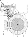
Figure 2 shows a smaller-scale section along line II-II inFigure 1 , in a different configuration of the cutting unit and with the additional representation of a web of labelling material cut by the cutting unit into a plurality of labels; -
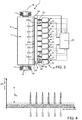
Figure 3 shows a schematic smaller-scale side view of the cutting unit ofFigure 1 with additional diagrammatic details of a control system of the cutting unit itself; -
Figures 4 to 6 diagrammatically show different possible operating conditions of the cutting unit ofFigures 1 to 3 ; -
Figures 7 shows an enlarged section view of a detail of the cutting unit ofFigure 2 in one possible operating condition and without the web of labelling material, the proportions of the parts being overemphasized for illustrative purposes and clarity reasons; -
Figure 8 is analogous toFigure 7 and shows the cutting unit cooperating with the web of labelling material; -
Figure 9 is analogous toFigure 7 and shows the same detail of theFigure 7 itself in a different condition and without the web of labelling material; -
Figure 10 is analogous toFigure 9 and shows the cutting unit cooperating with the web of labelling material; -
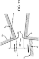
Figure 11 is analogous toFigures 7 and 9 and shows the same detail of these latter Figures in a further different condition and without the web of labelling material; -
Figure 12 is analogous toFigure 2 and shows a cutting unit according to the present invention, with parts removed for clarity; and -
Figure 13 is analogous toFigure 3 and shows the cutting unit ofFigure 12 with additional diagrammatic details of a control system of the cutting unit itself. -
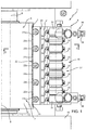
Number 1 inFigures 1 to 3 indicates as a whole a cutting unit not according to the present invention for cutting material from a web, inparticular labels 2 from aweb 3 of labelling material. -
Cutting unit 1 is adapted to be incorporated into a labelling machine (known per se and not shown), especially into a roll-fed labelling machine for applyinglabels 2 to relative articles, in particular containers (known per se and not shown) filled with a pourable product. - In detail, the roll-fed labelling machine substantially comprises:
- a label reel from which
web 3 is unwound along a path A from a motorized roll; - a carousel for advancing the articles to be labelled along an additional curved path; and
- a labelling unit for applying
labels 2 onto respective articles which are advanced by the carousel. - In a known manner, the labelling unit comprises:
- a web feeding device C including one or more motorized feeding rolls (known per se and not shown) for moving
web 3 from the label reel towards the carousel; - cutting
unit 1 for cutting onelabel 2 at any one time fromweb 3; and - a vacuum drum D (only partially shown in
Figure 2 ) receiving thecut labels 2 and transferring them to the articles in the carousel. -
Cutting unit 1 cutslabels 2 fromweb 3 and conveys them towards the carousel. - With reference to
Figures 1 to 3 ,cutting unit 1 substantially comprises: - a
stationary blade 4 mounted on astationary support structure 5; - a
rotary drum 6 rotating, in use, about a vertical axis B and having alateral surface 7 facingstationary blade 4 and receivingweb 3; and - at least one
rotary blade 8 borne bylateral surface 7 ofrotary drum 6 and cyclically passing, in use, bystationary blade 4 to define a cutting position, wherein thestationary blade 4 and therotary blade 8 cooperate, in use, with opposite sides of theweb 3 so as to separate alabel 2 from theweb 3 itself. - Axis B of
rotary drum 6 is parallel to the axis of vacuum drum D;rotary drum 6 and vacuum drum D are substantially arranged tangential to one another to allow transfer of thecut labels 2 from therotary drum 6 to the vacuum drum D. - In detail,
rotary drum 6 comprises acentral shaft 9 supported in a rotating manner about its axis B by afixed frame 10 through a pair ofbearings 11, in particular rolling bearings, and a cylindrical annularmain body 12, coaxially coupled ontoshaft 9 and delimited bylateral surface 7. - As clearly shown in
Figure 2 ,rotary blade 8 outwardly protrudes slightly fromlateral surface 7 ofrotary drum 6 and is provided with a cutting edge 15 (Figures 7 to 11 ) extending parallel to axis B. - As a possible alternative not shown,
rotary drum 6 may also comprise two or morerotary blades 8 equally spaced angularly about axis B. - In the particular example shown in
Figure 2 , axis ofrotary drum 6 extends orthogonally to path A followed byweb 3 at the cutting position. - With reference to
Figures 1 and2 ,support structure 5 comprises a verticalprismatic block 16 arranged in a position facinglateral surface 7 ofrotary drum 6 and carryingstationary blade 4 on one of its sides. - In particular,
stationary blade 4 is defined by a plate having two opposite and parallel flat lateral faces 17, 18, one of which rests, in use, on a relative side ofblock 16;stationary blade 4 also includes a front wedge-shapedcutting portion 19, protruding fromblock 16 towardsrotary drum 6, and aflat back surface 20 opposite thecutting edge 19. In the particular example shown, backsurface 20 abuts against aflange 21 outwardly protruding from the side ofblock 16 on whichstationary blade 4 is arranged. - Cutting
portion 19 ofstationary blade 4 has a linear and vertical cutting edge 22 (see in particularFigures 7 to 11 ) extending parallel to axis B ofrotary drum 6 and to cuttingedge 15 ofrotary blade 8. - As visible in the specific embodiment shown in
Figure 2 , which has no limiting effect, block 16 has aninternal cavity 23, which opens at a side of theblock 16 itself, opposite therotary drum 6, and is closed by acover plate 24 secured to saidblock 16. This specific arrangement permits to amplify, in use, the vibrations generated onstationary blade 4 by rotation of therotary drum 6; the aim of this amplification will be clarified later on. -
Stationary blade 4 andlateral surface 7 ofrotary drum 6 define apassage 25 forweb 3; at cutting position, i.e. whererotary blade 8 facesstationary blade 4, thepassage 25 reaches a minimum value set to allow a cutting action on theweb 3. - With reference to
Figures 1 to 3 , cuttingunit 1 further comprises: - sensor means 26 detecting, in use, a quantity R correlated to the distance or interference between
stationary blade 4 androtary blade 6 at the cutting position; and - actuator means 27 configured to adjust the position of
stationary blade 4 towards or away fromrotary drum 6 as a function of the quantity R detected by sensor means 26. - In particular, actuator means 27 are configured to produce micrometric displacements of
stationary blade 4 towards or away fromrotary drum 6. - Cutting unit also comprises (
Figure 3 ) acontrol unit 28 connected to sensor means 26 and to actuator means 27 and configured to control activation of the actuator means 27 so as to maintain the detected quantity R within a given threshold range R0 corresponding to a given air gap range between cuttingedge 22 ofstationary blade 4 and cuttingedge 15 ofrotary blade 8 at the cutting position (see in particularFigures 7 and 8 ). - Cutting
unit 1 also comprises atemperature sensor 29 arranged onstationary blade 4 and connected to controlunit 28. - According to the unit shown in
Figures 1 to 3 , sensor means 26 comprise twosensors 30 detecting the quantity R atdistinct zones edge 22 ofstationary blade 4 to give distinct measures of the distances between cuttingedge 15 ofrotary blade 8 and thezones cutting edge 22 itself. - In particular,
zones edge 22stationary blade 4. - As a possible alternative not shown, sensor means 26 may even comprise more than two
sensors 30. - In the example shown, quantity R is the acceleration of the vibrations transmitted by
stationary blade 4 to block 16 during rotation ofrotary drum 4. Hence,sensors 30 are accelerometers mounted onportions 31 ofblock 16 adjacent tozones edge 22 ofstationary blade 4. In particular, in this case, eachsensor 30 detects the acceleration of the vibrations transmitted by the correspondingzone edge 22 ofstationary blade 4 to block 16 during rotation ofrotary drum 6; such accelerations reach respective peaks at cutting position (see for example the diagrams ofFigures 4 to 6 ). - The applicant has noted that when the peaks detected by each
sensor 30 are comprised within the threshold range R0, corresponding to a given threshold air gap between cuttingedge 15 ofrotary blade 8 and therespective zone edge 22 ofstationary blade 4, the cutting operation is performed in the desired or optimal conditions. - The diagram of
Figure 4 shows the desired condition, wherein the peaks of acceleration are contained within the prescribed threshold range R0. - The diagram of
Figure 5 shows a condition, wherein, at a certain point, the peaks of acceleration start to be out of the prescribed threshold range Ro, i.e. they start to exceed the upper limit of such range. Activation of actuator means 27 bycontrol unit 28 permits to restore the correct condition. - The diagram of
Figure 6 shows a further condition, wherein some of the peaks are within the threshold range R0 and others are out of such range; there is no repeatability of the values detected. The applicant has noted that this condition corresponds to a failure ofbearings 11, which should be replaced. In this specific case,control unit 28 generates a warning signal and thecutting unit 1 has to be stopped to permit replacement ofbearings 11. - In practice,
control unit 28 is configured to generate a warning signal as the quantity R detected by one of thesensors 30 shows no repeatability in a given time interval corresponding to a given plurality of turns ofrotary drum 6. -
Figures 7 and 8 show an example of correct air gap between cuttingedge 15 ofrotary blade 8 and cuttingedge 22 ofstationary blade 4 at cutting position; the applicant has observed that such gap has to be comprised between 0 and 2 micrometers. -
Figures 9 and 10 show an example wherein there is interference of some micrometers between cuttingedge 15 ofrotary blade 8 and cuttingedge 22 ofstationary blade 4 at cutting position; this situation should be corrected to avoid excessive wear ofstationary blade 4 and subsequently a non-correct cutting action on theweb 3 of labelling material. -
Figure 11 shows a typical situation of failure ofbearings 11; the air gap between cuttingedge 15 ofrotary blade 8 and cuttingedge 22 ofstationary blade 4 at cutting position continuously varies. - With reference to
Figures 1 to 3 , actuator means 27 preferably comprise a plurality ofindependent actuator members 31 configured to produce independent micrometric displacements ofrespective areas 22c of cuttingedge 22 ofstationary blade 4. - It is pointed out that
areas 22c may be distinct fromzones -
Actuator members 31 are configured to adjust the position of therespective areas 22c of cuttingedge 22 ofstationary blade 4 by direct deformation of thestationary blade 4 itself and/or by deformation of corresponding portions offlange 21 ofblock 16 directly contacting thestationary blade 4. - In the specific example shown in
Figures 1 to 3 ,actuator members 31 are linear actuators, in particular screw actuators, externally supported byblock 16 and each having anoutput element 32 directly cooperating with a side offlange 21 opposite the one contacting backsurface 20 ofstationary blade 4. In this case, the micrometric displacements of eacharea 22c ofstationary blade 4 are obtained as a result of corresponding deformations produced by therespective actuator member 31 on the portion offlange 21 adjacent to saidarea 22c. - The operation of cutting
unit 1 is described starting from a configuration, in whichcutting edge 15 ofrotary blade 8 is in the cutting area. -
Web 3 is unwound from label reel and advanced along path A by the motorized roll. -
Web 3 is taken up at its end by suction by vacuum drum D, and advanced withinpassage 25 which is defined, on its opposite sides, by cuttingedge 22 ofstationary blade 4 andlateral surface 7 ofrotary drum 6. - Due to the rotation of
rotary drum 6 about axis B, at a certain time,rotary blade 8faces cutting edge 22 ofstationary blade 4 reaching the cutting position (Figures 2 ,7 and 8 ), in whichrotary blade 4 closespassage 25 so as to leave a minimum air gap. - In the cutting position, one
label 2 is cut from the remaining part ofweb 3 by the actions of cuttingedges stationary blades -
Sensors 30 continuously detect quantity R, in the example shown the acceleration of the vibrations produced onblock 16 bystationary blade 4 during rotation ofrotary drum 6; when the peaks of the detected quantity R by one ofsensors 30 exceeds the threshold range R0 (as for instance in the conditions ofFigures 5 ,9 and 10 ),control unit 28 activates one ormore actuator members 31 to produce given displacements ofstationary blade 4 at theareas 22c of cuttingedge 22 involved in such detection. - During the initial transitory time following the start-up of cutting
unit 1, as a result of the temperature detected bytemperature sensor 29 along with the quantity R detected bysensors 30,control unit 28 activates theactuator members 31 to maintain the air gap between cuttingedge 15 ofrotary blade 8 and cuttingedge 22 ofstationary blade 4 within the desired threshold range. - If the detected quantity R results in a plurality of peaks having different and not repeatable values, such as shown in the diagram of
Figure 6 ,control unit 28 generates a warning signal indicating a possible failure ofbearings 11, which have to be replaced. - Each
cut label 2 is conveyed by the suction action of vacuum drum D towards the carrousel where it is applied onto a relative article by the labelling group. - With reference to
Figures 12 and13 , number 1' indicates as a whole an embodiment of a cutting unit according to the present invention; as cutting unit 1' is similar to cuttingunit 1, the following description is limited to the differences between them, by using the same references, where possible, for identical or corresponding parts. - In particular, cutting unit 1' basically differs from cutting
unit 1 by usingpiezoelectric actuator members 31' instead oflinear actuator member 31. - In this case,
piezoelectric actuator members 31' directly act on back surface 20 - which preferably has an arcuate profile - ofstationary blade 4. As a possible alternative not shown,piezoelectric actuator members 31' may also act on a portion ofsupport structure 5 directly contacting thestationary blade 4. - Each
piezoelectric actuator member 31' can be selectively deformed under a control voltage signal CVS generated bycontrol unit 28 and selectively transmits its deformations tostationary blade 4 so as to produce corresponding displacements of therespective area 22c of cuttingedge 22 of thestationary blade 4 itself towards or away fromrotary drum 6. - Each
piezoelectric actuator member 31' is advantageously used as "sensor means" since it selectively transforms impacts of stationary androtary blades web 3 into corresponding detected-voltage values DVV correlated to the distance or interference between the stationary androtary blades respective area 22c of cuttingedge 22 on which saidpiezoelectric actuator member 31' operates. - The detected-voltage values DVV are transmitted from each
piezoelectric actuator member 31' to controlunit 28 as a detected-voltage signal DVS;control unit 28 generates a respective control voltage signal CVS for eachpiezoelectric actuator member 31' as a function of the detected-voltage signal DVS generated in use by the samepiezoelectric actuator member 31'. - This permits to detect the distance or interference between the stationary and
rotary blades area 22c of cuttingedge 22, without using corresponding sensors, which may complicate the general structure. - Analogously to cutting
unit 1,control unit 28 of cutting unit 1' is configured to generate a warning signal as the detected-voltage values DVV associated to one or more specificpiezoelectric actuator members 31' show no repeatability in a given time interval corresponding to a given plurality of turns ofrotary drum 6. - Finally, it should be noted that, in this specific embodiment,
support structure 5 has no internal cavity to amplify vibrations generated onstationary blade 4 by rotation of therotary drum 6, aspiezoelectric actuator members 31' do not detect accelerations of vibrations. - The advantages of cutting
units 1, 1' according to the present invention will be clear from the foregoing description. - In particular, thanks to the continuous detection of the distance between cutting
edge 15 ofrotary blade 8 and cuttingedge 22 ofstationary blade 4 at the cutting position as well as the consequent adjustment of the position of thestationary blade 4, it is possible to avoid any possible interference betweensuch cutting edges cutting unit 1. - This kind of control also applies during the initial transitory time following the start-up of the
cutting unit 1, wherein the temperatures of the stationary androtary blades blades - The proposed solution also permits to avoid possible problems of non-uniform wear or degradation of the
stationary blade 4 due to the use ofwebs 3 of different heights. As a matter of fact, by monitoring the behaviour of thestationary blade 4 at different zones of itscutting edge 22 permits thecontrol unit 28 to detect whether aweb 3 extending along only part of the entire height of thecutting edge 22 is used and to control theactuator members - Furthermore, as previously explained, the proposed solution permits to detect possible failures of
bearings 11. - Finally, the solution of
Figures 12 and13 permits to avoid to install additional sensors on thestationary blade 4 or onsupport structure 5, sincepiezoelectric actuator members 31' can be also used as "sensor means". - Clearly, changes may be made to cutting
units 1, 1' as described herein without, however, departing from the scope of protection as defined in the accompanying claims. - In particular, each cutting
unit 1, 1' may also comprise onesingle actuator member stationary blade 4.
Claims (7)
- A cutting unit (1, 1') for cutting material (2) from a web (3), said cutting unit (1, 1') comprising:- a stationary blade (4) mounted on a stationary support structure (5);- a rotary drum (6) rotating, in use, about an axis (B) and having a lateral surface (7) facing the stationary blade (4) and receiving the web (3); and- at least one rotary blade (8) borne by the lateral surface (7) of the rotary drum (6) and cyclically passing, in use, by the stationary blade (4) to define a cutting position, wherein the stationary blade (4) and the rotary blade (8) cooperate, in use, with opposite sides of the web (3) so as to separate material (2) from said web (3);actuator means (27) configured to adjust the position of the stationary blade (4) towards or away from the rotary drum (6) as a function of the detected distance or interference between said stationary blade (4) and said rotary blade (8) at the cutting position,
said stationary blade (4) and said rotary blade (8) have respective cutting edges (22, 15) cooperating in use with opposite sides of the web (3), and in that
said actuator means (27) comprise at least one actuator member (31, 31') configured to adjust the position of the cutting edge (22) of the stationary blade (4) towards or away from the rotary drum (6) by deformation of the stationary blade (4) itself and/or by deformation of a portion (21) of the support structure (5) directly contacting the stationary blade (4), and further comprising a control unit (28) connected to said actuator member (31, 31') and configured to control activation of said actuator member (31, 31') so as to maintain a given air gap range between the cutting edge (22) of the stationary blade (4) and the cutting edge (15) of the rotary blade (8) at the cutting position,
characterized in that said actuator member is a piezoelectric actuator member (31') selectively deformed under a control voltage signal (CVS) generated by said control unit (28) and selectively transmitting its deformations to the stationary blade (4) so as to produce corresponding displacements of the cutting edge (22) of the stationary blade (4) itself towards or away from the rotary drum (6), and
wherein said piezoelectric actuator member (31') selectively transforms impacts of the stationary and rotary blades (4, 8) on the web (3) into corresponding detected-voltage values (DVV) correlated to the distance or interference between the stationary and rotary blades (4, 8) themselves at the cutting position. - The cutting unit as claimed in claim 1, wherein said detected-voltage values (DVV) are transmitted from said piezoelectric actuator member (31') to said control unit (28) as a detected-voltage signal (DVS), and wherein said control unit (28) generates said control voltage signal (CVS) for said piezoelectric actuator member (31') as a function of said detected-voltage signal (DVS).
- The cutting unit as claimed in claim 1 or 2, wherein said control unit (28) is configured to generate a warning signal as the detected-voltage values (DVV) show no repeatability in a given time interval corresponding to a given plurality of turns of said rotary drum (6).
- The cutting unit as claimed in claim 1, wherein said actuator means (27) comprise a plurality of said actuator members (31, 31') configured to produce independent micrometric displacements of respective areas (22c) of the cutting edge (22) of the stationary blade (4) .
- The cutting unit as claimed in claim 1, further comprising a temperature sensor (29) arranged on the stationary blade (4) and connected to the control unit (28) .
- The cutting unit as claimed in claim 1, wherein said actuator means (27) are configured to produce micrometric displacements of the stationary blade (4) towards or away from the rotary drum (6).
- The cutting unit as claimed in claim 6, wherein said actuator member is a piezoelectric actuator member (31') selectively deformed under a control voltage signal (CVS) generated by said control unit (28) and selectively transmitting its deformations to the stationary blade (4) so as to produce corresponding displacements of the cutting edge (22) of the stationary blade (4) itself towards or away from the rotary drum (6).
Priority Applications (1)
| Application Number | Priority Date | Filing Date | Title |
|---|---|---|---|
| EP16305535.3A EP3243614B1 (en) | 2016-05-09 | 2016-05-09 | A cutting unit for a labelling machine |
Applications Claiming Priority (1)
| Application Number | Priority Date | Filing Date | Title |
|---|---|---|---|
| EP16305535.3A EP3243614B1 (en) | 2016-05-09 | 2016-05-09 | A cutting unit for a labelling machine |
Publications (2)
| Publication Number | Publication Date |
|---|---|
| EP3243614A1 EP3243614A1 (en) | 2017-11-15 |
| EP3243614B1 true EP3243614B1 (en) | 2019-10-09 |
Family
ID=55970939
Family Applications (1)
| Application Number | Title | Priority Date | Filing Date |
|---|---|---|---|
| EP16305535.3A Active EP3243614B1 (en) | 2016-05-09 | 2016-05-09 | A cutting unit for a labelling machine |
Country Status (1)
| Country | Link |
|---|---|
| EP (1) | EP3243614B1 (en) |
Families Citing this family (3)
| Publication number | Priority date | Publication date | Assignee | Title |
|---|---|---|---|---|
| BR112020025407A2 (en) * | 2018-06-15 | 2021-03-09 | Fabio Perini S.P.A. | DEVICE WITH ROTATING BLADES, MACHINE UNDERSTANDING SUCH DEVICE AND RELATED METHOD |
| DE102018127852A1 (en) * | 2018-11-08 | 2020-05-14 | Khs Gmbh | Cutting unit for a labeling unit and labeling unit with such a cutting unit |
| IT201800010637A1 (en) * | 2018-11-28 | 2020-05-28 | Perini Fabio Spa | PERFORATING DEVICE AND TRANSFORMATION MACHINE INCLUDING SAID DEVICE |
Family Cites Families (5)
| Publication number | Priority date | Publication date | Assignee | Title |
|---|---|---|---|---|
| US2782853A (en) * | 1955-08-08 | 1957-02-26 | American Viscose Corp | Precision fiber cutter |
| FI79256C (en) * | 1987-12-09 | 1989-12-11 | Ahlstroem Valmet | FOERFARANDE OCH ANORDNING FOER REGLERING AV SKAERBETTENS BETTMELLANRUM I EN ARKSKAERMASKIN. |
| DE19861021B4 (en) * | 1998-03-25 | 2004-10-28 | Eduard Küsters Maschinenfabrik GmbH & Co. KG | Device for processing a material web with ultrasound |
| DE19933497A1 (en) * | 1999-07-16 | 2001-01-18 | Rieter Automatik Gmbh | Gap adjustment device and method |
| EP2534709B1 (en) * | 2010-02-08 | 2015-01-14 | Sca Hygiene Products AB | Apparatus and method for treating products |
-
2016
- 2016-05-09 EP EP16305535.3A patent/EP3243614B1/en active Active
Non-Patent Citations (1)
| Title |
|---|
| None * |
Also Published As
| Publication number | Publication date |
|---|---|
| EP3243614A1 (en) | 2017-11-15 |
Similar Documents
| Publication | Publication Date | Title |
|---|---|---|
| EP3243614B1 (en) | A cutting unit for a labelling machine | |
| EP2847115B1 (en) | Controller and system for controllably rotating a roll of material | |
| US10829335B2 (en) | Providing a cutting area with web-like interleaver material | |
| JP5662572B2 (en) | Method for protecting a conversion unit for converting a web substrate, supply station and packaging material making machine | |
| CN111348474B (en) | Waste paper removing and winding device for continuous label paper | |
| EP2358508A1 (en) | Folder for adjustably tensioning a web and method of adjusting web tension as a web is cut | |
| JP2673657B2 (en) | Winding prevention device for web printing machine | |
| US20210252728A1 (en) | Device with rotating blades, machine comprising said device, and related method | |
| JP6006433B2 (en) | Printing apparatus and printing method | |
| EP2749420B1 (en) | System and method for preventing high tension from damaging a printing press | |
| CN108656764B (en) | Printing apparatus and control method of printing apparatus | |
| JP6054466B2 (en) | Sheet manufacturing equipment | |
| US6979815B2 (en) | Folding apparatus of a web-fed printing press including a conveyor belt monitoring device | |
| KR101790253B1 (en) | System for logsaw cutting mechine | |
| ITBO20090828A1 (en) | MACHINE LABELING. | |
| WO2022089826A1 (en) | Labelling machine and method for applying labels onto articles adapted to contain a pourable product | |
| WO2016123385A1 (en) | Label roll with a blank leader and method of manufacturing | |
| WO2020064436A1 (en) | Cutting unit and labeling machine having said cutting unit | |
| US20230202700A1 (en) | Container labeling machine | |
| EP2732941A1 (en) | A cutting unit for cutting a sheet or film material into lengths of predetermined size | |
| CN219156088U (en) | Rotary blade device and machine comprising the same | |
| US4197773A (en) | Device for cutting a web into predetermined sections | |
| JP5832840B2 (en) | Method for producing chemical-added crepe paper | |
| US20240109744A1 (en) | Device with rotating blades, machine comprising said device, and related method | |
| CN116946790A (en) | Function monitoring of conveyor belt in printing machine |
Legal Events
| Date | Code | Title | Description |
|---|---|---|---|
| PUAI | Public reference made under article 153(3) epc to a published international application that has entered the european phase |
Free format text: ORIGINAL CODE: 0009012 |
|
| STAA | Information on the status of an ep patent application or granted ep patent |
Free format text: STATUS: THE APPLICATION HAS BEEN PUBLISHED |
|
| AK | Designated contracting states |
Kind code of ref document: A1 Designated state(s): AL AT BE BG CH CY CZ DE DK EE ES FI FR GB GR HR HU IE IS IT LI LT LU LV MC MK MT NL NO PL PT RO RS SE SI SK SM TR |
|
| AX | Request for extension of the european patent |
Extension state: BA ME |
|
| STAA | Information on the status of an ep patent application or granted ep patent |
Free format text: STATUS: REQUEST FOR EXAMINATION WAS MADE |
|
| 17P | Request for examination filed |
Effective date: 20180430 |
|
| RBV | Designated contracting states (corrected) |
Designated state(s): AL AT BE BG CH CY CZ DE DK EE ES FI FR GB GR HR HU IE IS IT LI LT LU LV MC MK MT NL NO PL PT RO RS SE SI SK SM TR |
|
| STAA | Information on the status of an ep patent application or granted ep patent |
Free format text: STATUS: EXAMINATION IS IN PROGRESS |
|
| 17Q | First examination report despatched |
Effective date: 20180614 |
|
| GRAP | Despatch of communication of intention to grant a patent |
Free format text: ORIGINAL CODE: EPIDOSNIGR1 |
|
| STAA | Information on the status of an ep patent application or granted ep patent |
Free format text: STATUS: GRANT OF PATENT IS INTENDED |
|
| INTG | Intention to grant announced |
Effective date: 20190718 |
|
| GRAS | Grant fee paid |
Free format text: ORIGINAL CODE: EPIDOSNIGR3 |
|
| GRAA | (expected) grant |
Free format text: ORIGINAL CODE: 0009210 |
|
| STAA | Information on the status of an ep patent application or granted ep patent |
Free format text: STATUS: THE PATENT HAS BEEN GRANTED |
|
| AK | Designated contracting states |
Kind code of ref document: B1 Designated state(s): AL AT BE BG CH CY CZ DE DK EE ES FI FR GB GR HR HU IE IS IT LI LT LU LV MC MK MT NL NO PL PT RO RS SE SI SK SM TR |
|
| REG | Reference to a national code |
Ref country code: GB Ref legal event code: FG4D |
|
| REG | Reference to a national code |
Ref country code: CH Ref legal event code: EP |
|
| REG | Reference to a national code |
Ref country code: IE Ref legal event code: FG4D |
|
| REG | Reference to a national code |
Ref country code: DE Ref legal event code: R096 Ref document number: 602016022047 Country of ref document: DE |
|
| REG | Reference to a national code |
Ref country code: AT Ref legal event code: REF Ref document number: 1188262 Country of ref document: AT Kind code of ref document: T Effective date: 20191115 |
|
| REG | Reference to a national code |
Ref country code: NL Ref legal event code: MP Effective date: 20191009 |
|
| REG | Reference to a national code |
Ref country code: LT Ref legal event code: MG4D |
|
| REG | Reference to a national code |
Ref country code: AT Ref legal event code: MK05 Ref document number: 1188262 Country of ref document: AT Kind code of ref document: T Effective date: 20191009 |
|
| PG25 | Lapsed in a contracting state [announced via postgrant information from national office to epo] |
Ref country code: AT Free format text: LAPSE BECAUSE OF FAILURE TO SUBMIT A TRANSLATION OF THE DESCRIPTION OR TO PAY THE FEE WITHIN THE PRESCRIBED TIME-LIMIT Effective date: 20191009 Ref country code: PL Free format text: LAPSE BECAUSE OF FAILURE TO SUBMIT A TRANSLATION OF THE DESCRIPTION OR TO PAY THE FEE WITHIN THE PRESCRIBED TIME-LIMIT Effective date: 20191009 Ref country code: NL Free format text: LAPSE BECAUSE OF FAILURE TO SUBMIT A TRANSLATION OF THE DESCRIPTION OR TO PAY THE FEE WITHIN THE PRESCRIBED TIME-LIMIT Effective date: 20191009 Ref country code: LV Free format text: LAPSE BECAUSE OF FAILURE TO SUBMIT A TRANSLATION OF THE DESCRIPTION OR TO PAY THE FEE WITHIN THE PRESCRIBED TIME-LIMIT Effective date: 20191009 Ref country code: SE Free format text: LAPSE BECAUSE OF FAILURE TO SUBMIT A TRANSLATION OF THE DESCRIPTION OR TO PAY THE FEE WITHIN THE PRESCRIBED TIME-LIMIT Effective date: 20191009 Ref country code: NO Free format text: LAPSE BECAUSE OF FAILURE TO SUBMIT A TRANSLATION OF THE DESCRIPTION OR TO PAY THE FEE WITHIN THE PRESCRIBED TIME-LIMIT Effective date: 20200109 Ref country code: PT Free format text: LAPSE BECAUSE OF FAILURE TO SUBMIT A TRANSLATION OF THE DESCRIPTION OR TO PAY THE FEE WITHIN THE PRESCRIBED TIME-LIMIT Effective date: 20200210 Ref country code: LT Free format text: LAPSE BECAUSE OF FAILURE TO SUBMIT A TRANSLATION OF THE DESCRIPTION OR TO PAY THE FEE WITHIN THE PRESCRIBED TIME-LIMIT Effective date: 20191009 Ref country code: BG Free format text: LAPSE BECAUSE OF FAILURE TO SUBMIT A TRANSLATION OF THE DESCRIPTION OR TO PAY THE FEE WITHIN THE PRESCRIBED TIME-LIMIT Effective date: 20200109 Ref country code: FI Free format text: LAPSE BECAUSE OF FAILURE TO SUBMIT A TRANSLATION OF THE DESCRIPTION OR TO PAY THE FEE WITHIN THE PRESCRIBED TIME-LIMIT Effective date: 20191009 Ref country code: GR Free format text: LAPSE BECAUSE OF FAILURE TO SUBMIT A TRANSLATION OF THE DESCRIPTION OR TO PAY THE FEE WITHIN THE PRESCRIBED TIME-LIMIT Effective date: 20200110 |
|
| PG25 | Lapsed in a contracting state [announced via postgrant information from national office to epo] |
Ref country code: RS Free format text: LAPSE BECAUSE OF FAILURE TO SUBMIT A TRANSLATION OF THE DESCRIPTION OR TO PAY THE FEE WITHIN THE PRESCRIBED TIME-LIMIT Effective date: 20191009 Ref country code: IS Free format text: LAPSE BECAUSE OF FAILURE TO SUBMIT A TRANSLATION OF THE DESCRIPTION OR TO PAY THE FEE WITHIN THE PRESCRIBED TIME-LIMIT Effective date: 20200224 Ref country code: HR Free format text: LAPSE BECAUSE OF FAILURE TO SUBMIT A TRANSLATION OF THE DESCRIPTION OR TO PAY THE FEE WITHIN THE PRESCRIBED TIME-LIMIT Effective date: 20191009 |
|
| PG25 | Lapsed in a contracting state [announced via postgrant information from national office to epo] |
Ref country code: AL Free format text: LAPSE BECAUSE OF FAILURE TO SUBMIT A TRANSLATION OF THE DESCRIPTION OR TO PAY THE FEE WITHIN THE PRESCRIBED TIME-LIMIT Effective date: 20191009 |
|
| REG | Reference to a national code |
Ref country code: DE Ref legal event code: R097 Ref document number: 602016022047 Country of ref document: DE |
|
| PG2D | Information on lapse in contracting state deleted |
Ref country code: IS |
|
| PG25 | Lapsed in a contracting state [announced via postgrant information from national office to epo] |
Ref country code: EE Free format text: LAPSE BECAUSE OF FAILURE TO SUBMIT A TRANSLATION OF THE DESCRIPTION OR TO PAY THE FEE WITHIN THE PRESCRIBED TIME-LIMIT Effective date: 20191009 Ref country code: DK Free format text: LAPSE BECAUSE OF FAILURE TO SUBMIT A TRANSLATION OF THE DESCRIPTION OR TO PAY THE FEE WITHIN THE PRESCRIBED TIME-LIMIT Effective date: 20191009 Ref country code: RO Free format text: LAPSE BECAUSE OF FAILURE TO SUBMIT A TRANSLATION OF THE DESCRIPTION OR TO PAY THE FEE WITHIN THE PRESCRIBED TIME-LIMIT Effective date: 20191009 Ref country code: CZ Free format text: LAPSE BECAUSE OF FAILURE TO SUBMIT A TRANSLATION OF THE DESCRIPTION OR TO PAY THE FEE WITHIN THE PRESCRIBED TIME-LIMIT Effective date: 20191009 Ref country code: IS Free format text: LAPSE BECAUSE OF FAILURE TO SUBMIT A TRANSLATION OF THE DESCRIPTION OR TO PAY THE FEE WITHIN THE PRESCRIBED TIME-LIMIT Effective date: 20200209 |
|
| PGFP | Annual fee paid to national office [announced via postgrant information from national office to epo] |
Ref country code: DE Payment date: 20200421 Year of fee payment: 5 Ref country code: FR Payment date: 20200422 Year of fee payment: 5 |
|
| PLBE | No opposition filed within time limit |
Free format text: ORIGINAL CODE: 0009261 |
|
| STAA | Information on the status of an ep patent application or granted ep patent |
Free format text: STATUS: NO OPPOSITION FILED WITHIN TIME LIMIT |
|
| PG25 | Lapsed in a contracting state [announced via postgrant information from national office to epo] |
Ref country code: SK Free format text: LAPSE BECAUSE OF FAILURE TO SUBMIT A TRANSLATION OF THE DESCRIPTION OR TO PAY THE FEE WITHIN THE PRESCRIBED TIME-LIMIT Effective date: 20191009 Ref country code: SM Free format text: LAPSE BECAUSE OF FAILURE TO SUBMIT A TRANSLATION OF THE DESCRIPTION OR TO PAY THE FEE WITHIN THE PRESCRIBED TIME-LIMIT Effective date: 20191009 |
|
| PGFP | Annual fee paid to national office [announced via postgrant information from national office to epo] |
Ref country code: IT Payment date: 20200421 Year of fee payment: 5 |
|
| 26N | No opposition filed |
Effective date: 20200710 |
|
| PG25 | Lapsed in a contracting state [announced via postgrant information from national office to epo] |
Ref country code: ES Free format text: LAPSE BECAUSE OF FAILURE TO SUBMIT A TRANSLATION OF THE DESCRIPTION OR TO PAY THE FEE WITHIN THE PRESCRIBED TIME-LIMIT Effective date: 20191009 |
|
| PG25 | Lapsed in a contracting state [announced via postgrant information from national office to epo] |
Ref country code: SI Free format text: LAPSE BECAUSE OF FAILURE TO SUBMIT A TRANSLATION OF THE DESCRIPTION OR TO PAY THE FEE WITHIN THE PRESCRIBED TIME-LIMIT Effective date: 20191009 |
|
| PG25 | Lapsed in a contracting state [announced via postgrant information from national office to epo] |
Ref country code: MC Free format text: LAPSE BECAUSE OF FAILURE TO SUBMIT A TRANSLATION OF THE DESCRIPTION OR TO PAY THE FEE WITHIN THE PRESCRIBED TIME-LIMIT Effective date: 20191009 Ref country code: LI Free format text: LAPSE BECAUSE OF NON-PAYMENT OF DUE FEES Effective date: 20200531 Ref country code: CH Free format text: LAPSE BECAUSE OF NON-PAYMENT OF DUE FEES Effective date: 20200531 |
|
| REG | Reference to a national code |
Ref country code: BE Ref legal event code: MM Effective date: 20200531 |
|
| GBPC | Gb: european patent ceased through non-payment of renewal fee |
Effective date: 20200509 |
|
| PG25 | Lapsed in a contracting state [announced via postgrant information from national office to epo] |
Ref country code: LU Free format text: LAPSE BECAUSE OF NON-PAYMENT OF DUE FEES Effective date: 20200509 |
|
| PG25 | Lapsed in a contracting state [announced via postgrant information from national office to epo] |
Ref country code: IE Free format text: LAPSE BECAUSE OF NON-PAYMENT OF DUE FEES Effective date: 20200509 Ref country code: GB Free format text: LAPSE BECAUSE OF NON-PAYMENT OF DUE FEES Effective date: 20200509 |
|
| PG25 | Lapsed in a contracting state [announced via postgrant information from national office to epo] |
Ref country code: BE Free format text: LAPSE BECAUSE OF NON-PAYMENT OF DUE FEES Effective date: 20200531 |
|
| REG | Reference to a national code |
Ref country code: DE Ref legal event code: R119 Ref document number: 602016022047 Country of ref document: DE |
|
| PG25 | Lapsed in a contracting state [announced via postgrant information from national office to epo] |
Ref country code: DE Free format text: LAPSE BECAUSE OF NON-PAYMENT OF DUE FEES Effective date: 20211201 |
|
| PG25 | Lapsed in a contracting state [announced via postgrant information from national office to epo] |
Ref country code: TR Free format text: LAPSE BECAUSE OF FAILURE TO SUBMIT A TRANSLATION OF THE DESCRIPTION OR TO PAY THE FEE WITHIN THE PRESCRIBED TIME-LIMIT Effective date: 20191009 Ref country code: MT Free format text: LAPSE BECAUSE OF FAILURE TO SUBMIT A TRANSLATION OF THE DESCRIPTION OR TO PAY THE FEE WITHIN THE PRESCRIBED TIME-LIMIT Effective date: 20191009 Ref country code: FR Free format text: LAPSE BECAUSE OF NON-PAYMENT OF DUE FEES Effective date: 20210531 Ref country code: CY Free format text: LAPSE BECAUSE OF FAILURE TO SUBMIT A TRANSLATION OF THE DESCRIPTION OR TO PAY THE FEE WITHIN THE PRESCRIBED TIME-LIMIT Effective date: 20191009 |
|
| PG25 | Lapsed in a contracting state [announced via postgrant information from national office to epo] |
Ref country code: MK Free format text: LAPSE BECAUSE OF FAILURE TO SUBMIT A TRANSLATION OF THE DESCRIPTION OR TO PAY THE FEE WITHIN THE PRESCRIBED TIME-LIMIT Effective date: 20191009 |
|
| PG25 | Lapsed in a contracting state [announced via postgrant information from national office to epo] |
Ref country code: IT Free format text: LAPSE BECAUSE OF NON-PAYMENT OF DUE FEES Effective date: 20200509 |