EP3243606B1 - Exoskelettgelenkbetätigungsvorrichtung mit kugelschraube und zugelement - Google Patents
Exoskelettgelenkbetätigungsvorrichtung mit kugelschraube und zugelement Download PDFInfo
- Publication number
- EP3243606B1 EP3243606B1 EP17169586.9A EP17169586A EP3243606B1 EP 3243606 B1 EP3243606 B1 EP 3243606B1 EP 17169586 A EP17169586 A EP 17169586A EP 3243606 B1 EP3243606 B1 EP 3243606B1
- Authority
- EP
- European Patent Office
- Prior art keywords
- joint
- exoskeleton
- tensile member
- ball screw
- ball nut
- Prior art date
- Legal status (The legal status is an assumption and is not a legal conclusion. Google has not performed a legal analysis and makes no representation as to the accuracy of the status listed.)
- Revoked
Links
Images







Classifications
-
- A—HUMAN NECESSITIES
- A61—MEDICAL OR VETERINARY SCIENCE; HYGIENE
- A61H—PHYSICAL THERAPY APPARATUS, e.g. DEVICES FOR LOCATING OR STIMULATING REFLEX POINTS IN THE BODY; ARTIFICIAL RESPIRATION; MASSAGE; BATHING DEVICES FOR SPECIAL THERAPEUTIC OR HYGIENIC PURPOSES OR SPECIFIC PARTS OF THE BODY
- A61H3/00—Appliances for aiding patients or disabled persons to walk about
-
- A—HUMAN NECESSITIES
- A61—MEDICAL OR VETERINARY SCIENCE; HYGIENE
- A61H—PHYSICAL THERAPY APPARATUS, e.g. DEVICES FOR LOCATING OR STIMULATING REFLEX POINTS IN THE BODY; ARTIFICIAL RESPIRATION; MASSAGE; BATHING DEVICES FOR SPECIAL THERAPEUTIC OR HYGIENIC PURPOSES OR SPECIFIC PARTS OF THE BODY
- A61H1/00—Apparatus for passive exercising; Vibrating apparatus; Chiropractic devices, e.g. body impacting devices, external devices for briefly extending or aligning unbroken bones
- A61H1/02—Stretching or bending or torsioning apparatus for exercising
- A61H1/0237—Stretching or bending or torsioning apparatus for exercising for the lower limbs
-
- B—PERFORMING OPERATIONS; TRANSPORTING
- B25—HAND TOOLS; PORTABLE POWER-DRIVEN TOOLS; MANIPULATORS
- B25J—MANIPULATORS; CHAMBERS PROVIDED WITH MANIPULATION DEVICES
- B25J9/00—Program-controlled manipulators
- B25J9/0006—Exoskeletons, i.e. resembling a human figure
-
- B—PERFORMING OPERATIONS; TRANSPORTING
- B25—HAND TOOLS; PORTABLE POWER-DRIVEN TOOLS; MANIPULATORS
- B25J—MANIPULATORS; CHAMBERS PROVIDED WITH MANIPULATION DEVICES
- B25J17/00—Joints
-
- B—PERFORMING OPERATIONS; TRANSPORTING
- B25—HAND TOOLS; PORTABLE POWER-DRIVEN TOOLS; MANIPULATORS
- B25J—MANIPULATORS; CHAMBERS PROVIDED WITH MANIPULATION DEVICES
- B25J9/00—Program-controlled manipulators
- B25J9/10—Program-controlled manipulators characterised by positioning means for manipulator elements
- B25J9/104—Program-controlled manipulators characterised by positioning means for manipulator elements with cables, chains or ribbons
-
- A—HUMAN NECESSITIES
- A61—MEDICAL OR VETERINARY SCIENCE; HYGIENE
- A61H—PHYSICAL THERAPY APPARATUS, e.g. DEVICES FOR LOCATING OR STIMULATING REFLEX POINTS IN THE BODY; ARTIFICIAL RESPIRATION; MASSAGE; BATHING DEVICES FOR SPECIAL THERAPEUTIC OR HYGIENIC PURPOSES OR SPECIFIC PARTS OF THE BODY
- A61H2201/00—Characteristics of apparatus not provided for in the preceding codes
- A61H2201/12—Driving means
- A61H2201/1207—Driving means with electric or magnetic drive
-
- A—HUMAN NECESSITIES
- A61—MEDICAL OR VETERINARY SCIENCE; HYGIENE
- A61H—PHYSICAL THERAPY APPARATUS, e.g. DEVICES FOR LOCATING OR STIMULATING REFLEX POINTS IN THE BODY; ARTIFICIAL RESPIRATION; MASSAGE; BATHING DEVICES FOR SPECIAL THERAPEUTIC OR HYGIENIC PURPOSES OR SPECIFIC PARTS OF THE BODY
- A61H2201/00—Characteristics of apparatus not provided for in the preceding codes
- A61H2201/14—Special force transmission means, i.e. between the driving means and the interface with the user
-
- A—HUMAN NECESSITIES
- A61—MEDICAL OR VETERINARY SCIENCE; HYGIENE
- A61H—PHYSICAL THERAPY APPARATUS, e.g. DEVICES FOR LOCATING OR STIMULATING REFLEX POINTS IN THE BODY; ARTIFICIAL RESPIRATION; MASSAGE; BATHING DEVICES FOR SPECIAL THERAPEUTIC OR HYGIENIC PURPOSES OR SPECIFIC PARTS OF THE BODY
- A61H2201/00—Characteristics of apparatus not provided for in the preceding codes
- A61H2201/16—Physical interface with patient
- A61H2201/1602—Physical interface with patient kind of interface, e.g. head rest, knee support or lumbar support
- A61H2201/164—Feet or leg, e.g. pedal
- A61H2201/1642—Holding means therefor
-
- A—HUMAN NECESSITIES
- A61—MEDICAL OR VETERINARY SCIENCE; HYGIENE
- A61H—PHYSICAL THERAPY APPARATUS, e.g. DEVICES FOR LOCATING OR STIMULATING REFLEX POINTS IN THE BODY; ARTIFICIAL RESPIRATION; MASSAGE; BATHING DEVICES FOR SPECIAL THERAPEUTIC OR HYGIENIC PURPOSES OR SPECIFIC PARTS OF THE BODY
- A61H2201/00—Characteristics of apparatus not provided for in the preceding codes
- A61H2201/16—Physical interface with patient
- A61H2201/1602—Physical interface with patient kind of interface, e.g. head rest, knee support or lumbar support
- A61H2201/165—Wearable interfaces
-
- A—HUMAN NECESSITIES
- A61—MEDICAL OR VETERINARY SCIENCE; HYGIENE
- A61H—PHYSICAL THERAPY APPARATUS, e.g. DEVICES FOR LOCATING OR STIMULATING REFLEX POINTS IN THE BODY; ARTIFICIAL RESPIRATION; MASSAGE; BATHING DEVICES FOR SPECIAL THERAPEUTIC OR HYGIENIC PURPOSES OR SPECIFIC PARTS OF THE BODY
- A61H2201/00—Characteristics of apparatus not provided for in the preceding codes
- A61H2201/50—Control means thereof
-
- A—HUMAN NECESSITIES
- A61—MEDICAL OR VETERINARY SCIENCE; HYGIENE
- A61H—PHYSICAL THERAPY APPARATUS, e.g. DEVICES FOR LOCATING OR STIMULATING REFLEX POINTS IN THE BODY; ARTIFICIAL RESPIRATION; MASSAGE; BATHING DEVICES FOR SPECIAL THERAPEUTIC OR HYGIENIC PURPOSES OR SPECIFIC PARTS OF THE BODY
- A61H2201/00—Characteristics of apparatus not provided for in the preceding codes
- A61H2201/50—Control means thereof
- A61H2201/5058—Sensors or detectors
- A61H2201/5061—Force sensors
-
- A—HUMAN NECESSITIES
- A61—MEDICAL OR VETERINARY SCIENCE; HYGIENE
- A61H—PHYSICAL THERAPY APPARATUS, e.g. DEVICES FOR LOCATING OR STIMULATING REFLEX POINTS IN THE BODY; ARTIFICIAL RESPIRATION; MASSAGE; BATHING DEVICES FOR SPECIAL THERAPEUTIC OR HYGIENIC PURPOSES OR SPECIFIC PARTS OF THE BODY
- A61H2201/00—Characteristics of apparatus not provided for in the preceding codes
- A61H2201/50—Control means thereof
- A61H2201/5058—Sensors or detectors
- A61H2201/5071—Pressure sensors
-
- A—HUMAN NECESSITIES
- A61—MEDICAL OR VETERINARY SCIENCE; HYGIENE
- A61H—PHYSICAL THERAPY APPARATUS, e.g. DEVICES FOR LOCATING OR STIMULATING REFLEX POINTS IN THE BODY; ARTIFICIAL RESPIRATION; MASSAGE; BATHING DEVICES FOR SPECIAL THERAPEUTIC OR HYGIENIC PURPOSES OR SPECIFIC PARTS OF THE BODY
- A61H2205/00—Devices for specific parts of the body
- A61H2205/08—Trunk
- A61H2205/088—Hip
-
- A—HUMAN NECESSITIES
- A61—MEDICAL OR VETERINARY SCIENCE; HYGIENE
- A61H—PHYSICAL THERAPY APPARATUS, e.g. DEVICES FOR LOCATING OR STIMULATING REFLEX POINTS IN THE BODY; ARTIFICIAL RESPIRATION; MASSAGE; BATHING DEVICES FOR SPECIAL THERAPEUTIC OR HYGIENIC PURPOSES OR SPECIFIC PARTS OF THE BODY
- A61H2205/00—Devices for specific parts of the body
- A61H2205/10—Leg
-
- F—MECHANICAL ENGINEERING; LIGHTING; HEATING; WEAPONS; BLASTING
- F16—ENGINEERING ELEMENTS AND UNITS; GENERAL MEASURES FOR PRODUCING AND MAINTAINING EFFECTIVE FUNCTIONING OF MACHINES OR INSTALLATIONS; THERMAL INSULATION IN GENERAL
- F16H—GEARING
- F16H19/00—Gearings comprising essentially only toothed gears or friction members and not capable of conveying indefinitely-continuing rotary motion
- F16H19/02—Gearings comprising essentially only toothed gears or friction members and not capable of conveying indefinitely-continuing rotary motion for interconverting rotary or oscillating motion and reciprocating motion
- F16H19/06—Gearings comprising essentially only toothed gears or friction members and not capable of conveying indefinitely-continuing rotary motion for interconverting rotary or oscillating motion and reciprocating motion comprising flexible members, e.g. an endless flexible member
- F16H19/0622—Gearings comprising essentially only toothed gears or friction members and not capable of conveying indefinitely-continuing rotary motion for interconverting rotary or oscillating motion and reciprocating motion comprising flexible members, e.g. an endless flexible member for converting reciprocating movement into oscillating movement and vice versa, the reciprocating movement is perpendicular to the axis of oscillation
-
- F—MECHANICAL ENGINEERING; LIGHTING; HEATING; WEAPONS; BLASTING
- F16—ENGINEERING ELEMENTS AND UNITS; GENERAL MEASURES FOR PRODUCING AND MAINTAINING EFFECTIVE FUNCTIONING OF MACHINES OR INSTALLATIONS; THERMAL INSULATION IN GENERAL
- F16H—GEARING
- F16H25/00—Gearings comprising primarily only cams, cam-followers and screw-and-nut mechanisms
- F16H25/18—Gearings comprising primarily only cams, cam-followers and screw-and-nut mechanisms for conveying or interconverting oscillating or reciprocating motions
- F16H25/20—Screw mechanisms
- F16H2025/2062—Arrangements for driving the actuator
-
- F—MECHANICAL ENGINEERING; LIGHTING; HEATING; WEAPONS; BLASTING
- F16—ENGINEERING ELEMENTS AND UNITS; GENERAL MEASURES FOR PRODUCING AND MAINTAINING EFFECTIVE FUNCTIONING OF MACHINES OR INSTALLATIONS; THERMAL INSULATION IN GENERAL
- F16H—GEARING
- F16H25/00—Gearings comprising primarily only cams, cam-followers and screw-and-nut mechanisms
- F16H25/18—Gearings comprising primarily only cams, cam-followers and screw-and-nut mechanisms for conveying or interconverting oscillating or reciprocating motions
- F16H25/20—Screw mechanisms
- F16H25/22—Screw mechanisms with balls, rollers, or similar members between the co-operating parts; Elements essential to the use of such members
- F16H25/2204—Screw mechanisms with balls, rollers, or similar members between the co-operating parts; Elements essential to the use of such members with balls
Definitions
- the present invention relates to a device that augments a user's strength and/or aids in the prevention of injury during the performance of certain motions or tasks. More particularly, the present invention relates to a device suitable for therapeutic use with patients that have impaired neuromuscular/muscular function of the appendages or a device suitable for use by a person engaging in heavy tool use or weight bearing tasks. These devices include a set of artificial limbs, with these artificial limbs being movable by actuators under the direction of control systems, that potentiate improved function of the person's appendages for activities including, but not limited to, enabling walking for a disabled person, granting greater strength and endurance in a wearer's arms, or allowing for more weight to be carried by a wearer while walking.
- Wearable exoskeletons have been designed for medical, commercial, and military applications. Medical exoskeleton devices are being developed to restore and rehabilitate proper muscle function for people with disorders that affect muscle control. Medical exoskeleton devices are a system of motorized braces that can apply forces to the wearer's appendages. In a rehabilitation setting, medical exoskeletons are controlled by a physical therapist who uses one of a plurality of possible input means to command an exoskeleton control system. In turn, the medical exoskeleton control system actuates the position of the motorized braces, resulting in the application of force to, and typically movement of, the body of the exoskeleton wearer. Medical exoskeletons can also be used outside of a therapeutic setting to grant improved mobility to a disabled individual.
- Tool-holding exoskeletons help prevent injury and augment the exoskeleton wearer's strength.
- Commercial and military exoskeletons are used to alleviate loads supported by workers or soldiers during their labor or other activities, thereby preventing worker injuries and increasing their stamina and strength.
- Tool-holding exoskeletons are outfitted with a tool-holding arm that supports the weight of the tool, reducing user fatigue by providing tool-holding assistance.
- the tool-holding arm transfers the vertical force required to hold the tool through the legs of the exoskeleton rather than through the user's arms and body.
- weight-bearing exoskeletons transfer the weight of the exoskeleton load through the legs of the exoskeleton rather than through the user's legs.
- weight-bearing exoskeletons are designed to carry a specific load, such as a heavy backpack.
- military weight-bearing exoskeletons support the weight of armor.
- Commercial and military exoskeletons can have actuated joints that augment the strength of the exoskeleton wearer, with these actuated joints being controlled by the exoskeleton control system, and with the exoskeleton wearer using any of a plurality of possible input means to command the exoskeleton control system.
- exoskeleton control systems prescribe and control trajectories in the joints of an exoskeleton, resulting in the movement of the exoskeleton.
- These control trajectories can be prescribed as position-based, force-based, or a combination of both methodologies, such as those seen in impedance controllers.
- Position-based control systems can be modified directly through modification of the prescribed positions.
- Force-based control systems can also be modified directly through modification of the prescribed force profiles.
- Complicated exoskeleton movements such as walking in an ambulatory medical exoskeleton
- an exoskeleton control system through the use of a series of exoskeleton trajectories, with increasingly complicated exoskeleton movements requiring an increasingly complicated series of exoskeleton trajectories.
- These series of trajectories can be cyclic, such as the exoskeleton taking a series of steps with each leg, or they can be discrete, such as an exoskeleton rising from a seated position into a standing position.
- exoskeleton control system should take into account these differences in wearer proportion, exoskeleton configuration/customization, and exoskeleton-wearer fit, resulting in changes to prescribed exoskeleton trajectories.
- exoskeleton control systems assign trajectories to the joints of the exoskeleton and control the positions of these joints
- actuators can take many forms, as is known in the art, each with advantages and disadvantages in various applications.
- the actuator exerting force on a joint is typically constituted by an electric motor located proximal to that joint.
- Co-location of the actuator with the joint has advantages in terms of mechanical and design simplicity, but it has certain disadvantages - foremost among them is that adding an electric motor to a joint increases the bulk of the joint, limiting maneuverability of the joint and exoskeleton in certain environments.
- 4,843,921 uses a drive mechanism in which an electric motor twists on a loop of cord, with this cord loop forming a helical structure and shortening as it is twisted, causing the length of cord to shorten and pull the two ends of the cord loop closer together. In this way, the activation of the electric motor is used to apply a pulling force over distance through the cord loop. This allows for a design in which the motor driving the movement of a joint is located at a position distal from the joint.
- a ball screw is a mechanical device that allows rotational motion to be translated into linear motion.
- These devices such as those described in U.S. Patent Nos. 2,855,791 and 3,667,311 , or other forms known in the art, are comprised of a threaded shaft that acts as a raceway for ball bearings and a nut that moves over the ball bearings as it travels along the threaded shaft, with the translation of the ball nut along the length of the shaft being driven by the rotation of the threaded shaft.
- These devices have mechanisms to allow the recirculation of ball bearings within the ball nut as the ball nut moves along the threaded shaft.
- Ball screw devices are used in automotive steering, aircraft or missile control surfaces, and robotics systems - including high-precision robotic systems such as those used in semiconductor manufacturing.
- Ball screws are designed for straight-line axial thrust, with any type of transverse force or side load greatly reducing ball screw life and rapidly decreasing mechanical efficacy prior to failure.
- ball screw actuators include devices such as precision rails and/or linear bearings, or other similar devices known in the art. The devices to prevent side load tend to be substantial in relation to the ball screw, increasing the size and weight of an actuator system (both undesirable characteristics in exoskeleton applications).
- an exoskeleton actuator could be developed that combines the linear motion (and high efficiency) of a ball screw system with the force-transfer-over-distance features of tensile member actuators.
- Such a system would allow the electric motors and other components of the ball screw to be placed away from the joint, and the linear motion of the ball screw would allow the tensile members to transfer force by translating rather than twisting, resulting in decreased wear.
- a number of disadvantages to such a design exist as well.
- the mechanisms of most robotic/exoskeleton actuators allow the actuator to exert force in two joint movement directions, those being flexion and extension in the case of the knee.
- a tensile member is only able to transfer force through a pulling motion, allowing force to be applied to a joint and effecting motion in only one direction.
- some exoskeleton joint actuators have used springs or other similar devices to cause a joint to return to a position when the current to the motor is disengaged, this is not suitable for the forces required to move the large joints of a human exoskeleton and/or the body of the wearer.
- US 2011/167945 discloses a robot joint driving apparatus comprising a bidirectional ball screw actuator with a ball nut and a cable having two portions extending from the ball nut in a first direction and two portions extending from the ball nut in a second direction opposite the first direction.
- the present invention provides an exoskeleton as claimed in claim 1.
- the present invention provides a method for causing movement of an exoskeleton as claimed in claim 11.
- the ball nut assembly has a first cord reactor and a second cord reactor. The first tensile member is routed through the first cord reactor, and the second tensile member is routed through the second cord reactor.
- the joint includes a joint pulley.
- the joint is configured such that rotation of the joint pulley causes the second support to move relative to the first support about the joint.
- the first tensile member is coupled to the joint pulley
- the second tensile member is coupled to the joint pulley.
- the first tensile member has a first end and a second end, and the first and second ends of the first tensile member are coupled to the joint pulley.
- the second tensile member has a first end and a second end, and the first and second ends of the second tensile member are coupled to the joint pulley.
- the actuator further includes a first plurality of pulleys configured to guide the first tensile member and a second plurality of pulleys configured to guide the second tensile member.
- the first tensile member runs parallel to the ball screw between the ball nut assembly and each of the first plurality of pulleys.
- the second tensile member runs parallel to the ball screw between the ball nut assembly and each of the second plurality of pulleys.
- the actuator further includes an additional pulley configured to guide the first tensile member.
- each of the first plurality of pulleys is oriented in a first plane, and the additional pulley is oriented in a second plane.
- the actuator further includes a motor configured to cause rotation of the ball screw.
- the first support is a torso brace
- the second support is an upper leg support
- the joint is a hip joint.
- the ball nut assembly has a load cell configured to detect a force applied to the ball nut assembly by the first or second tensile member.
- the cords of these loops are configured such that as the ball nut travels axially along the ball screw, a parallel portion of cords translates with the ball nut, resulting in relative shortening of the cords on one side of the joint pulley and relative lengthening of the cords on the opposing side of the joint pulley, with this cord configuration allowing linear movement of the ball nut to be transferred by the cords into rotational movement at the joint.
- torque applied by the electric motor results in thrust at the ball nut, with this thrust resulting in translation of the cords, with this translation of the cords resulting in torque at the joint pulley.
- the parallel routing of the cords proximate to the ball screw is such that the cords maintain the axial position of the ball nut along the ball screw, with this preventing side loads on the ball screw, removing the need for guide rails on the ball screw mechanism and reducing the weight of the device.
- prototype human exoskeleton hip actuation devices were developed, with these devices being comprised of electrically driven ball screw mechanisms mounted on the rear of an exoskeleton, with the linear movement of the ball nut resulting in translation of tensile members, with these tensile members being routed through a series of guide pulleys onto a hip joint pulley such that the bidirectional linear movement of the ball nut along the ball screw results in bidirectional rotational movement at the hip joint.
- a load cell is incorporated into the ball nut, with this load cell being in communication with the exoskeleton control system, with the exoskeleton control system also being in communication with the electrical motors that drive the ball screw mechanism.
- these prototypes contain two actuator devices, with the electric motor and ball screw of the mechanism of each actuator being affixed to the rear of the exoskeleton in an over-under configuration to minimize bulk.
- a linear actuator 100 has a ball screw 101, with ball screw 101 being rotatably connected to a rear actuator housing 109 by a rear bearing 104 and a front actuator housing 108 by a front bearing 105.
- a ball nut 102 travels along ball screw 101 between a rear stopper 107 and a front stopper 106.
- Ball nut 102 has a ball bearing recirculation mechanism 103 and a grease nipple 110.
- Ball nut 102 is guided along ball screw 101 between an outer precision rail 111 and an inner precision rail 112.
- a motor (not shown) can be attached to linear actuator 100 at a motor mount 113, with such a motor driving the rotation of ball screw 101.
- ball screw 101 results in the movement of ball nut 102 along ball screw 101 between outer precision rail 111 and inner precision rail 112.
- ball bearings (not shown) roll between ball screw 101 and ball nut 102, with ball nut recirculation mechanism 103 returning the ball bearings to ball nut 102, while grease nipple 101 providing lubrication for the ball screw mechanism.
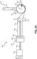
- an actuator 200 includes a ball screw 201, with ball screw 201 being driven by an electric motor 202 and rotating about a bearing 214.
- a ball nut assembly 203 travels along the length of ball screw 201 in response to the rotation of ball screw 201, with the rotation of ball screw 201 being effected by motor 202.
- Ball nut assembly 203 is comprised of a ball nut body 204 and a cord reactor 209.
- a cord 205 passes through cord reactor 209, with the ends of cord 205 being affixed to a joint pulley body 206 of a joint pulley 215 at cord terminators 207 and 208.
- Cord 205 is guided between cord reactor 209 and joint pulley 215 by guide pulleys 211 and 212 such that the portions of cord 205 that extend along the length of ball screw 201 are parallel with ball screw 201.
- Joint pulley body 206 of joint pulley 215 rotates about a pivot 210, with a joint extension 213 protruding from the structure of joint pulley 215.
- Engaging motor 202 causes ball screw 201 to rotate, which causes ball nut assembly 203 to translate linearly along the length of ball screw 201.
- Figure 2B shows ball nut assembly 203 moving toward motor 202 relative to the position of ball nut assembly 203 shown in Figure 2A .
- This movement of ball nut assembly 203 results in cord 205, which is looped through cord reactor 209, being pulled away from joint pulley 215.
- the tension applied by cord 205 on joint pulley 215 causes rotation of joint pulley 215 about pivot 210 such that the position of joint extension 213 changes from a joint position 216, shown in Figure 2A , to a joint position 217, shown in Figure 2B .
- motor torque is converted to thrust by a ball screw mechanism, and thrust from the ball screw mechanism is converted to torque at joint pulley 215 by a system of tensile members.
- a bidirectional actuator 220 includes ball screw 201, with ball screw 201 being driven by motor 202 and rotating about bearing 214.
- a ball nut assembly 250 travels along the length of ball screw 201 in response to the rotation of ball screw 201, with the rotation of ball screw 201 being effected by motor 202.
- Ball nut assembly 250 is comprised of a ball nut body 255, a first cord reactor 260, and a second cord reactor 261.
- Cord 205 passes through first cord reactor 260, with the ends of cord 205 being affixed to a joint pulley body 265 of a joint pulley 270 at cord terminators 275 and 276.
- Cord 205 is guided between first cord reactor 260 and joint pulley 270 by guide pulleys 211 and 212 such that the portions of cord 205 that extend along the length of ball screw 201 are parallel with ball screw 201.
- a cord 225 passes through second cord reactor 261, with the ends of cord 225 being affixed to joint pulley body 265 of joint pulley 270 at cord terminators 227 and 228.
- Cord 225 is guided between second cord reactor 261 and joint pulley 270 by guide pulleys 221- 224 such that the portions of cord 225 that extend along the length of ball screw 201 are parallel with ball screw 201.
- Joint pulley body 265 of joint pulley 270 rotates about pivot 210, with joint extension 213 protruding from the structure of joint pulley 270.
- Engaging motor 202 causes ball screw 201 to rotate, which causes ball nut assembly 250 to translate linearly along the length of ball screw 201.
- the direction ball nut assembly 250 travels in is determined by the direction of rotation of ball screw 201.
- Figure 2D shows ball nut assembly 250 moving away from motor 202 relative to the position of ball nut assembly 250 shown in Figure 2C .
- This movement of ball nut assembly 250 results in cord 225, which is looped through second cord reactor 261, being pulled away from motor 202 such that tension is applied to joint pulley 270 by cord 225.
- cord 205 which is looped through first cord reactor 260, is moved toward and wrapped around joint pulley 270, with this movement preventing tension from being applied to joint pulley 270 by cord 205.
- the net result of these changes in applied force to joint pulley 270 is the rotation of joint pulley 270 about pivot 210, which causes the position of joint extension 213 to change from joint position 216, shown in Figure 2C , to a joint position 218, shown in Figure 2D .
- actuator 220 is configured such that both cords 205, 225 are held in relative tension, as shown in Figures 2C and 2D , any movement of ball nut assembly 250, as driven by motor 202 rotating ball screw 201, will result in movement of joint pulley 270, allowing bidirectional control of the rotation of joint pulley 270 by a bidirectional motor ( i.e. , motor 202).
- a bidirectional motor i.e. , motor 202
- a somewhat more complex configuration of the first embodiment is shown. This configuration uses additional guide pulleys, including pulleys that guide both sides of a cord concurrently and pulleys that guide the cord into another plane.
- a bidirectional actuator 230 includes ball screw 201, with ball screw 201 being driven by motor 202 and rotating about bearing 214.
- Ball nut assembly 250 travels along the length of ball screw 201 in response to the rotation of ball screw 201, with the rotation of ball screw 201 being effected by motor 202.
- Ball nut assembly 250 is comprised of ball nut body 255, first cord reactor 260, and second cord reactor 261.
- Cord 205 passes through first cord reactor 260, with the ends of cord 205 being affixed to joint pulley body 265 of joint pulley 270 at cord terminators 275 and 276.
- Cord 205 is guided between first cord reactor 260 and joint pulley 270 by guide pulleys 211, 212, and 235-237.
- the portions of cord 205 located on opposite sides of first cord reactor 260 are routed close to one another in a paired strand length 238 between guide pulley 235 and joint pulley 270.
- the portions of cord 205 that extend along the length of ball screw 201 are parallel with ball screw 201.
- Cord 225 passes through second cord reactor 261, with the ends of cord 225 being affixed to joint pulley body 265 of joint pulley 270 at cord terminators 227 and 228.
- Cord 225 is guided between second cord reactor 261 and joint pulley 270 by guide pulleys 221-224 and 231-233.
- the portions of cord 225 located on opposite sides of second cord reactor 261 are routed close to one another in a paired strand length 234 between guide pulley 231 and joint pulley 270.
- the portions of cord 225 that extend along the length of ball screw 201 are parallel with ball screw 201.
- Figures 2E and 2F include a coordinate system with an X-axis labeled 280, a Y-axis labeled 281, and a Z-axis labeled 282. All guide pulleys are oriented in the X-Y plane other than guide pulleys 233 and 237. Guide pulleys 233 and 237 are oriented in the X-Z plane to guide cords 225 and 205, respectively, onto joint pulley 270, which is also oriented in the X-Z plane. Joint pulley body 265 of joint pulley 270 rotates about pivot 210, with joint extension 213 protruding from the structure of joint pulley 270.
- cords 205 and 225 are high-strength and/or zero-creep cords. In some embodiments, tensile members other than cords are used, e.g. , metal cables.
- the primary embodiment of the present invention consider a soldier wearing a powered exoskeleton in a combat environment, with this exoskeleton providing power to the joints of the exoskeleton that are involved in exoskeleton walking. If this exoskeleton were equipped with the device of the primary embodiment, power could be provided to the joints of the exoskeleton, such as the hip, without adding bulk to the joint. This is useful to a person wearing an exoskeleton that needs to move through tight spaces, where bulky joints could snag on obstacles such as walls or brush and obstruct the passage of the exoskeleton.
- leg joint bulk would be reduced, improving the mobility and maneuverability of the exoskeleton in tight spaces or cluttered environments.
- a heavy precision rail is not required in this type of ball screw linear actuator, reducing the weight and bulk of the actuator and exoskeleton as a whole - with lighter weight being desirable in exoskeletons for reasons including exoskeleton speed and power consumption.
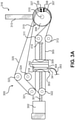
- FIG. 3A The second embodiment of the present invention is shown in Figures 3A-C .
- an actuator 300 is shown, with actuator 300 including a ball screw 301.
- Ball screw 301 is driven by an electric motor 302 and rotates about a bearing 314.
- a ball nut assembly 303 travels along the length of ball screw 301 in response to the rotation of ball screw 301, with the rotation of ball screw 301 being effected by motor 302.
- ball nut assembly 303 is shown being comprised of a ball nut body 304, a first cord reactor 309, a second cord reactor 319, a load cell 342, a load cell interface port 341, and a data cable 343.
- Data cable 343 connects to the exoskeleton control system or another sensor or control system (not shown).
- a cord 305 passes through first cord reactor 309, with the ends of cord 305 being affixed to a joint pulley body 306 of a joint pulley 315 at cord terminators 307 and 308.
- Cord 305 is guided between first cord reactor 309 and joint pulley 315 by guide pulleys 311 and 312 such that the portions of cord 305 that extend along the length of ball screw 301 are parallel with ball screw 301.
- a cord 325 passes through second cord reactor 319, with the ends of cord 325 being affixed to joint pulley body 306 of joint pulley 315 at cord terminator 327 and cord terminator 328.
- Cord 325 is guided between second cord reactor 319 and joint pulley 315 by guide pulleys 321-324 such that the portions of cord 325 that extend along the length of ball screw 301 are parallel with ball screw 301.
- Joint pulley body 306 of joint pulley 315 rotates about a pivot 310, with a joint extension 313 protruding from the structure of joint pulley 315.
- Engaging motor 302 causes ball screw 301 to rotate, which causes ball nut assembly 303 to translate linearly along the length of ball screw 301.
- the direction ball nut assembly 303 travels in is determined by the direction of rotation of ball screw 301. Movement of ball nut assembly 303 causes joint pulley body 306 to rotate about pivot 310 such that the position of joint extension 313 changes.
- Figures 3B and 3C represent exploded and assembled views, respectively, of ball nut assembly 303.
- Figures 3B and 3C provide more detailed views of ball nut assembly 303.
- Ball nut assembly 303 is comprised of a ball nut 351, ball nut body 304, a cord reactor body 352, a load cell ring 353, load cell 342, load cell interface port 341, a washer 354, a load cell shaft 355, and a load cell ring 356.
- a load cell screwcap 357 and fasteners 360 hold ball nut assembly 303 together.
- load cells such as load cell 342 have poor overload protection and are prone to damage when overloaded.
- the load cell used was the FUTEK ® Model LTH300, a donut load cell, which detects compressive force, although it can be configured, as in the second embodiment, to detect bidirectional force (as described in FUTEK ® Doc No. EL1058 regarding Model No. LTH300).
- the configuration of ball nut assembly 303 is such that, as motor 302 of actuator 300 is engaged to rotate joint 315, load cell 342 detects the force being applied upon cord reactor body 352 due to the tension of cord 305 or cord 325.
- the forces on cords 305 and 325 are proportional to the forces being applied on joint pulley 315 and joint extension 313, allowing the exoskeleton control system (not shown) to better control the position of the joint, including reducing force to prevent injury to a wearer or increasing force when greater joint assistance is needed.
- load cell 342 can detect forces being exerted upon the joint when actuator 300 and motor 302 are not engaged.
- other types of sensors known in the art are used to detect force at ball nut assembly 303.
- the exoskeleton provides power to the joints of the exoskeleton that are involved in exoskeleton walking.
- the exoskeleton is equipped with the device of the primary embodiment, with the actuator of the primary embodiment providing power to the hips of the exoskeleton.
- the power provided to the hips of the exoskeleton is controlled by the exoskeleton control system, which uses sensors and a wearer interface to detect the intentions of the soldier wearing the exoskeleton to direct the hip-actuator-effected movements of the hips.
- the movement of the legs may be obstructed, such as when the leg of the exoskeleton is blocked in movement by an obstacle or snag.
- the actuator continued to apply force on a joint that was unable to move (perhaps even at the command of the exoskeleton wearer)
- components of the exoskeleton actuator such as cords or other tensile members
- exoskeleton structure could fail, resulting in a disabled exoskeleton - a highly undesirable outcome in a combat setting.
- the exoskeleton control system can control the amount of force applied to the joint within preset constraints so as to prevent failure of exoskeleton or actuator components.
- force-sensing data provided to the exoskeleton control system from the actuator is useful in coordination of exoskeleton and wearer movements, improving the speed and agility of the exoskeleton and improving the ease of use to the wearer.
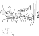
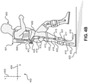
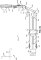
- Exoskeleton 401 includes a torso brace 409, with torso brace 409 connecting to a rear mount 411, and with rear mount 411 connecting to strapping 408 and a hip actuator 430.
- Hip actuator 430 has a cover 413 and internal components 431.
- Hip actuator 430 is rotatably connected to an upper leg support 412 at a hip joint 410, with upper leg support 412 being rotatably connected to a lower leg support 417 at a knee joint 415, and with lower leg support 417 being rotatably connected to a boot 418 by an ankle joint 433.
- Hip joint 410 is collocated with a hip 414 of person 400
- knee joint 415 is collocated with a knee 416 of person 400
- ankle joint 433 is collocated with an ankle 419 of person 400.
- Upper leg support 412 and lower leg support 417 are selectively coupled to a leg 422 of person 400 by thigh strapping 432 and shank strapping 421, respectively.
- the weight of exoskeleton 401 is transferred around person 400, with the weight of torso brace 409 passing through rear mount 411 to hip actuator 430, through upper leg support 412 to lower leg support 417, to boot 418, and ultimately into a support surface 420.
- Figures 4A and 4B show person 400, exoskeleton 401, and hip actuator 430 in an X-Y plane 402 (with X-Y plane 402 being formed by an X-axis 404 and a Y-axis-403).
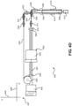
- Figure 4C is an overhead view of hip actuator 430 in an X-Z plane 405 (with X-Z plane 405 being formed by X-axis 404 and a Z-axis 406).
- Figure 4D is a rear view of hip actuator 430 in a Y-Z plane 407 (with Y-Z plane 407 being formed by Y-axis 403 and Z-axis 406).
- Figure 4E is a side view of hip actuator 430 in X-Y plane 402.
- Figure 4F is a detailed view of hip actuator 430.
- Figure 4E shows imperfect alignment of some actuator components with the described planes (particularly the relative alignment of X-Y plane 402 with the other planes described); the planes in these figures are shown for explanatory purposes as to the function of the hip actuator device, rather than being intended to rigidly bind components into planes that are at 90-degree angles to each other. In some embodiments, more than three planes can be used to define the position and function of the device.
- hip actuator 430 includes a ball screw 501, with ball screw 501 being driven by an electric motor 502 and rotating about a bearing 514.
- a ball nut assembly 503 travels along the length of ball screw 501, along Z-axis 406, in response to the rotation of ball screw 501, with the rotation of ball screw 501 being effected by motor 502.
- the movement of ball nut assembly 503 along ball screw 501 is restricted by ball nut assembly stops 540 and 546.
- Ball nut assembly 503 is comprised of a ball nut body 504, a first cord reactor 509, and a second cord reactor 519.
- a cord 505 passes through first cord reactor 509, with the ends of cord 505 being affixed to a joint pulley body 506 of a joint pulley 515 at cord terminators 507 and 508.
- Cord 505 is guided between first cord reactor 509 and joint pulley 515 by guide pulleys 511, 512, 535, and 539.
- the portions of cord 505 located on opposite sides of first cord reactor 509 are routed close to one another in a paired strand length 538 between guide pulley 535 and joint pulley 515.
- the portions of cord 505 that extend along the length of ball screw 501 are parallel with ball screw 501.
- a cord 525 passes through second cord reactor 519, with the ends of cord 525 being affixed to joint pulley body 506 of joint pulley 515 at cord terminator 527 and 528.
- Cord 525 is guided between second cord reactor 519 and joint pulley 515 by guide pulleys 521-524, 531, and 533.
- the portions of cord 525 located on opposite sides of second cord reactor 519 are routed close to one another in a paired strand length 534 between guide pulley 531 and joint pulley 515.
- the portions of cord 525 that extend along the length of ball screw 501 are parallel with ball screw 501.
- Guide pulleys 511, 512, 523, 524, 531, and 535 rotate in X-Z plane 405.
- Guide pulleys 521 and 522 rotate in Y-Z plane 407.
- Guide pulleys 533 and 539, joint pulley 515, motor 502, and ball screw 501 rotate in X-Y plane 4
- Rotation of motor 502 drives the rotation of ball screw 501, effecting linear movement of ball nut assembly 503 along ball screw 501 and Z-axis 406.
- the linear movement of ball nut assembly 503 results in the translation of cords 505 and 525, with cords 505 and 525 traveling in opposite directions while cords 505 and 525 are parallel to ball screw 501 in Z-axis 406.
- Relative movement of cords 505 and 525 applies force upon joint pulley 515, resulting in rotation of joint pulley 515 in X-Y plane 402 at hip joint 410, with this causing movement of a joint extension 513 relative to hip joint 410.
- the movement of joint extension 513 results in movement of upper leg support 412 relative to hip actuator 430.
- motor-effected movement of ball nut assembly 503 to the right along Z-axis 406 results in counterclockwise rotation of joint pulley 515 in X-Y plane 402 (shown in Figure 4E ).
- This causes flexion of upper leg support 412 of exoskeleton 401 at hip joint 410 and extension of leg 422 of person 400 at hip 414 (shown in Figures 4A and 4B ).
- motor 502 were to drive ball screw 501 in the opposite direction
- motor-effected movement of ball nut assembly 503 to the left along Z-axis 406 results in clockwise rotation of joint pulley 515 in X-Y plane 402 (shown in Figure 4E ).
- This causes extension of upper leg support 412 of exoskeleton 401 at hip joint 410 and flexion of leg 422 of person 400 at hip 414 (shown in Figures 4A and 4B ).
- the guide pulleys transferring the force from the ball screw actuator to the joint pulley are arrayed differently and/or in a different number.
- tensile member guides other than pulleys are used.
- the tensile members are zero-creep cords. In some embodiments, tensile members other than cords are used, e.g. , metal cables.
- motor 502 is placed in parallel with ball screw 501 rather than in line with it, with rotation of ball screw 501 being driven by a gear, wheel, belt, or other system known in the art. Note that the prototype of the third embodiment also included the load cell device and ball nut assembly device of the second embodiment.
- the third embodiment of the present invention consider a soldier wearing a powered exoskeleton in a combat environment, with this exoskeleton providing power to the joints of the exoskeleton that are involved in exoskeleton walking. If this exoskeleton were equipped with the hip actuator device of the third embodiment, power could be provided to the hip joint of the exoskeleton without adding bulk to the joint. This is useful to a person wearing an exoskeleton that needs to move through tight spaces, where bulky joints could snag on obstacles such as walls or brush and obstruct the passage of the exoskeleton. Through use of the device of the third embodiment of the exoskeleton hip joint, hip joint bulk would be reduced, improving the mobility and maneuverability of the exoskeleton in tight spaces or cluttered environments.
- a heavy precision rail is not required in this type of ball screw linear actuator, reducing the weight and bulk of the actuator and exoskeleton as a whole - with lighter weight being desirable in exoskeletons for reasons including exoskeleton speed and power consumption.
- An additional advantage of this actuator design is that it results in efficient electric actuation at the hip, in large part due to the mechanical efficiency of the ball screw actuator, with this efficient actuation increasing the range and/or speed of a powered exoskeleton.
- FIG. 5A-C The fourth embodiment of the present invention is shown in Figures 5A-C .
- the fourth embodiment is very similar but not identical to the third embodiment of the present invention.
- the electric motor and ball screw actuators are configured in an over-under configuration in the device of the fourth embodiment.
- each individual actuator functions in a manner identical to that described in the third embodiment.
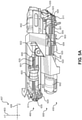
- Figure 5A is a rear view of a dual leg hip actuator device 600, with dual leg hip actuator device 600 including hip actuator 430 and a hip actuator 460 as the right and left hip actuators, respectively.
- Left hip actuator 460 has a motor 602, a ball screw 601, a ball nut assembly 603, a ball nut stop 640, a cord 605, a cord 625, a guide pulley 611, a guide pulley 624, and a guide pulley 635. Additional components of left hip actuator 460 are not shown in this figure, although left hip actuator 460 is constructed in the same manner as right hip actuator 430 (described in connection with the third embodiment) except that left hip actuator 460 is designed for the left hip rather than the right hip.
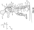
- Exoskeleton 451 includes torso brace 409, with torso brace 409 connecting to rear mount 411, and with rear mount 411 connecting to strapping 408 and dual leg hip actuator device 600.
- Dual leg hip actuator device 600 includes right hip actuator 430 and left hip actuator 460, as shown in Figure 5B .
- Dual leg hip actuator device 600 also includes a cover 462 and vents 463, as shown in Figure 5C .
- Left hip actuator 460 is rotatably connected to an upper leg support 712 at a hip joint 710, with upper leg support 712 being rotatably connected to a lower leg support 717 at a knee joint 715, and with lower leg support 717 being rotatably connected to a boot 718 by an ankle joint 733.
- Hip joint 710 is collocated with a hip 714 of person 450
- knee joint 715 is collocated with a knee 716 of person 450
- ankle joint 733 is collocated with an ankle 719 of person 450.
- Upper leg support 712 and lower leg support 717 are selectively coupled to a leg 722 of person 450 by thigh strapping 732 and shank strapping 721, respectively.
- exoskeleton 451 is transferred around person 450, with the weight of torso brace 409 passing through rear mount 411 to dual leg hip actuator device 600, through upper leg support 712 to lower leg support 717, to boot 718, and ultimately into support surface 420.
- motor-effected movement of ball nut assembly 603 to the left along Z-axis 406 results in counterclockwise rotation of a joint pulley 615 in X-Y plane 402 (shown in Figure 5B ).
- This causes extension of upper leg support 712 of exoskeleton 451 at hip joint 710 and extension of leg 722 of person 450 at hip 714 (shown in Figures 5B and 5C ).
- motor 602 were to drive ball screw 601 in the opposite direction
- motor-effected movement of ball nut assembly 603 to the right along Z-axis 406 results in clockwise rotation of joint pulley 615 in X-Y plane 402 (shown in Figure 5B ).
- This causes flexion of upper leg support 712 of exoskeleton 451 at hip joint 710 and flexion of leg 722 of person 450 at hip 714 (shown in Figures 5B and 5C ).
- the positions of the upper and lower linear actuators are swapped ( i.e. , right hip actuator 430 is located above left hip actuator 460).
- the fourth embodiment of the present invention consider a soldier wearing a powered exoskeleton in a combat environment, with this exoskeleton providing power to the joints of the exoskeleton that are involved in exoskeleton walking. If this exoskeleton were equipped with the dual hip actuator device of the fourth embodiment, power could be provided to each hip joint of the exoskeleton without adding bulk to the joints. This is useful to a person wearing an exoskeleton that needs to move through tight spaces, where bulky joints could snag on obstacles such as walls or brush and obstruct the passage of the exoskeleton. Through use of the device of the fourth embodiment of the exoskeleton hip joint, hip joint bulk would be reduced, improving the mobility and maneuverability of the exoskeleton in tight spaces or cluttered environments.
- the actuator of the present invention is shown being used to cause movement of an exoskeleton hip joint in certain embodiments, it should be recognized that the actuator can be used with other joints.
- the actuator can be used with elbow joints (not shown), knee joints (e.g. , knee joint 415) and ankle joints ( e.g. , ankle joint 433).
- the actuator of the present invention causes a first support and a second support to move relative to one another about the joint being actuated.
- These supports can take the form of a torso brace and an upper leg support (e.g ., torso brace 409 and upper leg support 412), an upper leg support and a lower leg support ( e.g ., upper leg support 412 and lower leg support 417), a lower leg support and a boot ( e.g ., lower leg support 417 and boot 418) or an upper arm support and a lower arm support (not shown), for instance.
- a torso brace and an upper leg support e.g ., torso brace 409 and upper leg support 412
- an upper leg support and a lower leg support e.g ., upper leg support 412 and lower leg support 417
- a lower leg support and a boot e.g ., lower leg support 417 and boot 418) or an upper arm support and a lower arm support (not shown), for instance.
- various embodiments of the present invention can be combined.
- various sensors including but not limited to pressure sensors or toggle switches, can be in communication with the exoskeleton control system, allowing the exoskeleton to respond to the user.
- various types of sensors are used to determine the position of the actuator or joint.
- various additional types of sensors are used to detect the forces exerted upon the joint.
- bellows completely or partially enclose ball-screw-mechanism working surfaces to prevent dust or grit contamination of the ball screw mechanism.
- the ball screw actuators, cords, guide pulleys, and/or tensile member attachment points are placed differently on the exoskeleton structure.
- the tensile members can be routed differently across the exoskeleton structure, including the use of devices imparting mechanical advantage.
- guide rails can be employed for the ball nut assembly.
- a ball nut with recirculating balls is replaced by a rolling ring drive, and the ball screw is replaced with a "threadless ballscrew" rotating rod drive mechanism.
- the bearings are set at an angle to the threadless rod, with this angle determining the direction and rate of linear motion of the rolling ring drive per revolution of the rod, as driven by the motor.
- the present invention provides a device for use in human exoskeletons that allows for force to be exerted on a joint, effecting bidirectional movement of the joint, with this device being located away from the joint.
- the device is highly efficient at the transfer of force from an electrical motor or other power source to the joint, minimizing energy consumption and/or maximizing force applied to the joint.
- the device is low profile and adds little bulk at the joint being powered.
- the device can incorporate a robust and simple system for force sensing, allowing the exoskeleton control system to accurately control the position and force applied to the joint.
Landscapes
- Engineering & Computer Science (AREA)
- Mechanical Engineering (AREA)
- Robotics (AREA)
- Health & Medical Sciences (AREA)
- Life Sciences & Earth Sciences (AREA)
- Pain & Pain Management (AREA)
- Physical Education & Sports Medicine (AREA)
- Rehabilitation Therapy (AREA)
- Epidemiology (AREA)
- Animal Behavior & Ethology (AREA)
- General Health & Medical Sciences (AREA)
- Public Health (AREA)
- Veterinary Medicine (AREA)
- Manipulator (AREA)
- Rehabilitation Tools (AREA)
- General Engineering & Computer Science (AREA)
- Transmission Devices (AREA)
Claims (15)
- Exoskelett (401, 451), umfassend:eine erste Stütze (412, 417), die ausgelegt ist, um mit einem Exoskelettträger gekoppelt zu sein;eine zweite Stütze (412, 417), die ausgelegt ist, um mit dem Exoskelettträger gekoppelt zu sein;ein Gelenk (315; 410, 415, 433), das die erste Stütze (412, 417) und die zweite Stütze (412, 417) untereinander verbindet; undeinen Aktuator (200; 220; 230; 300; 430; 460), der Folgendes einschließt:eine Kugelschraube (101; 201; 301; 501; 601);eine Kugelmutterbaugruppe (203; 250; 303; 503; 603), die mit der Kugelschraube (101...601) für Bewegung entlang der Kugelschraube (101...601) gekoppelt ist; undmindestens ein Spannelement (205; 225; 305, 325; 505, 525; 605, 625), das mit der Kugelmutterbaugruppe (203...603) so verbunden ist, dass sich der erste und der zweite Abschnitt des mindestens einen Spannelements (205...625) von der Kugelmutterbaugruppe (203...603) in eine erste Richtung erstrecken und sich der dritte und der vierte Abschnitt des mindestens einen Spannelement (205...625) von der Kugelmutterbaugruppe (203...603) in eine zweite Richtung entgegen der ersten Richtung erstrecken, wobei:
der erste und zweite Abschnitt an gegenüberliegenden Seiten der Kugelschraube (101...601) voneinander gelegen sind, der dritte und vierte Abschnitt an gegenüberliegenden Seiten der Kugelschraube (101 ...601) voneinander gelegen sind, wobei ein Abschnitt des mindestens einen Spannelements (205...625) durch die Kugelmutterbaugruppe (203...603) durchgeht, um den ersten und zweiten Abschnitt direkt aneinander zu verbinden, wobei ein Abschnitt des mindestens einen Spannelements (205...625) durch die Kugelmutterbaugruppe (203...603) durchgeht, um den dritten und vierten Abschnitt direkt aneinander zu verbinden, und wobei der Aktuator (200...460) so ausgelegt ist, dass:Bewegung der Kugelmutterbaugruppe (203...603) entlang der Kugelschraube (101...601) in die erste Richtung verursacht, dass sich die zweite Stütze (412, 417) im Verhältnis zu der ersten Stütze (412, 417) in eine erste Rotationsrichtung um das Gelenk (315...433) bewegt; undBewegung der Kugelmutterbaugruppe (203...603) entlang der Kugelschraube (101...601) in die zweite Richtung verursacht, dass sich die zweite Stütze (412, 417) im Verhältnis zu der ersten Stütze (412, 417) in eine zweite Rotationsrichtung um das Gelenk (315...433) bewegt. - Exoskelett (401, 451) nach Anspruch 1, wobei:das Gelenk (315...433) eine Gelenkriemenscheibe (215; 270; 315; 515; 615) einschließt;das Gelenk (315...433) so ausgelegt ist, dass Rotation der Gelenkriemenscheibe (215...615) verursacht, dass sich die zweite Stütze (412, 417) im Verhältnis zu der ersten Stütze (412, 417) um das Gelenk (315...433) bewegt; unddas mindestens eine Spannelement (205...625) mit der Gelenkriemenscheibe (215...615) verbunden ist.
- Exoskelett (401, 451) nach einem der vorstehenden Ansprüche, wobei:das mindestens eine Spannelement (205...625) ein erstes Spannelement (205...625) und ein zweites Spannelement (205...625) einschließt;das erste Spannelement (205...625) ein erstes Ende und ein zweites Ende aufweist;das erste und das zweite Ende des ersten Spannelement (205...625) mit der Gelenkriemenscheibe (215...615) gekoppelt sind;das zweite Spannelement (205...625) ein erstes Ende und ein zweites Ende aufweist; unddas erste und das zweite Ende des zweiten Spannelements (205...625) mit der Gelenkriemenscheibe (215...615) gekoppelt sind.
- Exoskelett (401, 451) nach einem der vorstehenden Ansprüche, wobei der Aktuator (200...460) weiter Folgendes einschließt:eine erste Vielzahl von Riemenscheiben (211, 212; 221-224, 231-233, 235-237; 311, 312, 321-324; 511, 512, 521-524, 531, 533, 535, 539, 611, 624, 635) die ausgelegt sind, um den ersten und den zweiten Abschnitt des mindestens einen Spannelements (205...625) zu führen; undeine zweite Vielzahl von Riemenscheiben (211 ...635), die ausgelegt sind, um den dritten und den vierten Abschnitt des mindestens einen Spannelements (205...625) zu führen.
- Exoskelett (401, 451) nach einem der vorstehenden Ansprüche, wobei der erste und der zweite Abschnitt des mindestens einen Spannelements (205...625) parallel zu der Kugelschraube (101...601) zwischen der Kugelmutterbaugruppe (203...603) und der ersten Vielzahl von Riemenscheiben (211...635) verlaufen, und der dritte und der vierte Abschnitt des mindestens einen Spannelements (205...625) parallel zu der Kugelschraube (101...601) zwischen der Kugelmutterbaugruppe (203...603) und der zweiten Vielzahl von Riemenscheiben (211 ...635) verlaufen.
- Exoskelett (401, 451) nach einem der vorstehenden Ansprüche, wobei der Aktuator (200...460) weiter eine zusätzliche Riemenscheibe (211...635) einschließt, die ausgelegt ist, um das mindestens eine Spannelement (205...625) zu führen.
- Exoskelett (401, 451) nach Anspruch 6, wobei jede der ersten Vielzahl von Riemenscheiben (211...635) in eine erste Ebene ausgerichtet ist, und die zusätzliche Riemenscheibe (211...635) in eine zweite Ebene ausgerichtet ist.
- Exoskelett (401, 451) nach einem der vorstehenden Ansprüche, wobei die Kugelmutterbaugruppe (203...603) eine Lastzelle (342) einschließt, die ausgelegt ist, um eine Kraft zu erkennen, die von dem mindestens einen Spannelement (205...625) auf die Kugelmutterbaugruppe (203...603) ausgeübt wird.
- Exoskelett (401, 451) nach einem der vorstehenden Ansprüche, wobei der Aktuator (200...460) weiter einen Motor (202; 303; 502; 602) einschließt, der ausgelegt ist, um Rotation der Kugelschraube (101...601) zu verursachen.
- Exoskelett (401, 451) nach einem der vorstehenden Ansprüche, wobei:die erste Stütze (412, 417) ein Oberkörperhalter (409) ist;die zweite Stütze (412, 417) eine Oberschenkelstütze (412, 417); unddas Gelenk (315...433) ein Hüftgelenk ist.
- Verfahren zum Verursachen von Bewegung eines Exoskeletts (401, 451), das eine erste Stütze (412, 417) einschließt, die mit einem Exoskelettträger (401, 451) gekoppelt ist, eine zweite Stütze (412, 417), die mit dem Exoskelettträger (401, 451) gekoppelt, ein Gelenk (315...433), das die erste Stütze (412, 417) mit der zweiten Stütze (412, 417) verbindet, und einen Aktuator (200...460), wobei der Aktuator (200...460) eine Kugelschraube (101...601), eine Kugelmutterbaugruppe (203...603), die mit der Kugelschraube (101...601) gekoppelt ist, und mindestens ein Spannelement (205...625) einschließt, wobei das mindestens eine Spannelement (205...625) mit der Kugelmutterbaugruppe (203...603) so verbunden ist, dass sich der erste und der zweite Abschnitt des mindestens einen Spannelements (205...625) von der Kugelmutterbaugruppe (203...603) in eine erste Richtung erstrecken und sich der dritte und der vierte Abschnitte des mindestens einen Spannelements (205...625) von der Kugelmutterbaugruppe (203...603) in eine zweite zur ersten Richtung gegenüberliegenden Richtung erstrecken, wobei:
der erste und zweite Abschnitt an gegenüberliegenden Seiten der Kugelschraube (101...601) voneinander gelegen sind, der dritte und vierte Abschnitte an gegenüberliegenden Seiten der Kugelschraube (101 ...601) voneinander gelegen sind, wobei ein Abschnitt des mindestens einen Spannelements (205...625) durch die Kugelmutterbaugruppe (203...603) durchgeht, um den ersten und zweiten Abschnitt direkt aneinander zu verbinden, wobei ein Abschnitt des mindestens einen Spannelements (205...625) durch die Kugelmutterbaugruppe (203...603) durchgeht, um den dritten und vierten Abschnitt direkt aneinander zu verbinden, und wobei das Verfahren Folgendes umfasst:Bewegen der Kugelmutterbaugruppe (203...603) entlang der Kugelschraube (101...601) in die erste Richtung, um zu verursachen, dass sich die zweite Stütze (412, 417) im Verhältnis zu der ersten Stütze (412, 417) in eine erste Rotationsrichtung um das Gelenk (315...433) bewegt; undBewegen der Kugelmutterbaugruppe (203...603) entlang der Kugelschraube (101...601) in die zweite Richtung, um zu verursachen, dass die sich die zweite Stütze (412, 417) im Verhältnis zu der ersten Stütze (412, 417) in eine zweite Rotationsrichtung um das Gelenk (315...433) bewegt. - Verfahren nach Anspruch 11, wobei das Gelenk (315...433) eine Gelenkriemenscheibe (215...615) einschließt, das mindestens eine Spannelement (205...625) ein erstes Spannelement (205...625) und ein zweites Spannelement (205...625) einschließt, das erste Spannelement (205...625) ein erstes Ende und ein zweites Ende aufweist, das mit der Gelenkriemenscheibe (215...615) gekoppelt ist, und das zweite Spannelement (205...625) ein erstes Ende und ein zweites Ende aufweist, das mit der Gelenkriemenscheibe (215...615) gekoppelt ist, wobei das Verfahren weiter Rotieren der Gelenkriemenscheibe (215...615) umfasst, um zu verursachen, dass sich die zweite Stütze (412, 417) im Verhältnis zu der ersten Stütze (412, 417) um das Gelenk (315...433) bewegt.
- Verfahren nach einem der Ansprüche 11 oder 12, weiter umfassend:Führen des ersten und des zweiten Abschnitts des mindestens einen Spannelements (205...625) mit einer ersten Vielzahl von Riemenscheiben (211...635); undFühren des dritten und des vierten Abschnitts des mindestens einen Spannelements (205...625) mit einer zweiten Vielzahl von Riemenscheiben (211 ...635).
- Verfahren nach einem der Ansprüche 11 bis 13, weiter umfassend Führen des mindestens einen Spannelements (205...625) mit einer zusätzlichen Riemenscheibe (211...635), wobei jede der ersten Vielzahl von Riemenscheiben (211...635) in einer ersten Ebene ausgerichtet ist, und die zusätzliche Riemenscheibe (211...635) in eine zweite Ebene, die von der ersten Ebene unterschiedlich ist, ausgerichtet ist.
- Verfahren nach einem der Ansprüche 11 bis 14, wobei die Kugelmutterbaugruppe (203...603) eine Lastzelle (342) einschließt, wobei das Verfahren weiter Folgendes umfasst:Erkennen durch die Lastzelle (342) einer Kraft, die von dem mindestens einen Spannelement (205...625) auf die Kugelmutterbaugruppe (203...603) ausgeübt wird; undSteuern des Aktuators (200...460) auf der Grundlage der Kraft.
Applications Claiming Priority (1)
| Application Number | Priority Date | Filing Date | Title |
|---|---|---|---|
| US201662331781P | 2016-05-04 | 2016-05-04 |
Publications (2)
| Publication Number | Publication Date |
|---|---|
| EP3243606A1 EP3243606A1 (de) | 2017-11-15 |
| EP3243606B1 true EP3243606B1 (de) | 2022-02-16 |
Family
ID=58671479
Family Applications (1)
| Application Number | Title | Priority Date | Filing Date |
|---|---|---|---|
| EP17169586.9A Revoked EP3243606B1 (de) | 2016-05-04 | 2017-05-04 | Exoskelettgelenkbetätigungsvorrichtung mit kugelschraube und zugelement |
Country Status (3)
| Country | Link |
|---|---|
| US (1) | US10702441B2 (de) |
| EP (1) | EP3243606B1 (de) |
| CN (1) | CN107343843B (de) |
Cited By (1)
| Publication number | Priority date | Publication date | Assignee | Title |
|---|---|---|---|---|
| WO2025098561A1 (de) * | 2023-11-06 | 2025-05-15 | ReActive Robotics GmbH | Vorrichtung zur kopplung einer extremität einer person mit einem bewegungsmechanismus |
Families Citing this family (43)
| Publication number | Priority date | Publication date | Assignee | Title |
|---|---|---|---|---|
| JP6553577B2 (ja) * | 2016-11-04 | 2019-07-31 | 本田技研工業株式会社 | 動作補助装置及び動力伝達機構 |
| SE542072C2 (en) * | 2017-06-19 | 2020-02-18 | Tendo Ab | A device for pivoting a body member around a joint |
| JP1607841S (de) * | 2017-07-12 | 2019-12-23 | ||
| JP1605289S (de) * | 2017-07-18 | 2019-11-25 | ||
| JP1605288S (de) * | 2017-07-18 | 2019-11-25 | ||
| JP1605285S (de) * | 2017-07-18 | 2019-11-25 | ||
| JP1605286S (de) * | 2017-07-18 | 2019-11-25 | ||
| JP1605287S (de) * | 2017-07-18 | 2019-11-25 | ||
| FR3075914B1 (fr) * | 2017-12-22 | 2019-12-20 | Commissariat A L`Energie Atomique Et Aux Energies Alternatives | Actionneur reversible a deux axes non synchronises avec un seul moteur |
| CN108354785B (zh) * | 2017-12-27 | 2019-09-20 | 温州职业技术学院 | 一种无动力行走助力柔性外骨骼装置 |
| JP1615135S (de) * | 2018-03-29 | 2020-03-30 | ||
| JP1615133S (de) * | 2018-03-29 | 2020-03-30 | ||
| JP1615136S (de) * | 2018-03-29 | 2020-03-30 | ||
| JP1615134S (de) * | 2018-03-29 | 2020-03-30 | ||
| JP1623231S (de) * | 2018-04-18 | 2020-07-13 | ||
| JP1623232S (de) * | 2018-04-18 | 2020-07-13 | ||
| CN110524512B (zh) * | 2018-05-23 | 2024-07-02 | 深圳市丞辉威世智能科技有限公司 | 动力传输机构和机器人 |
| CN109044742B (zh) * | 2018-08-07 | 2020-03-13 | 华东理工大学 | 一种康复型下肢外骨骼 |
| DE102018119755A1 (de) * | 2018-08-14 | 2020-02-20 | Ottobock Se & Co. Kgaa | Vorrichtung zum Unterstützen wenigstens eines Armes eines Benutzers |
| RU188814U1 (ru) * | 2018-08-20 | 2019-04-24 | Дмитрий Валерьевич Хачатуров | Актуатор ноги робота-гуманоида |
| CN109209792B (zh) * | 2018-09-30 | 2020-02-21 | 华中科技大学 | 一种基于双向滚珠丝杠传动的膝关节发电装置及其应用 |
| FR3089359B1 (fr) * | 2018-11-30 | 2022-01-07 | Commissariat Energie Atomique | Capteur d'effort pour actionneur à câble |
| ES2773112A1 (es) * | 2019-01-09 | 2020-07-09 | Gogoa Mobility Robots S L | Sistema robotizado portatil para la rehabilitacion funcional asistida de articulaciones |
| RU2712068C1 (ru) * | 2019-01-24 | 2020-01-24 | Общество с ограниченной ответственностью "ЭКЗОТЕХНОЛОГИИ" (ООО "Экзотехнологии") | Экзоскелет нижних конечностей |
| CN109700643B (zh) * | 2019-02-22 | 2020-04-24 | 武汉理工大学 | 多功能助行机器人 |
| USD921734S1 (en) * | 2019-03-07 | 2021-06-08 | Hyundai Motor Company | Wearable industrial robotic exoskeleton |
| USD924957S1 (en) * | 2019-03-26 | 2021-07-13 | Hyundai Motor Company | Wearable walking-assistance robot |
| US20210129046A1 (en) * | 2019-10-30 | 2021-05-06 | WeldFit Corporation | Apparatus and Associated Methods for Cleaning Slug Catcher |
| KR102752450B1 (ko) | 2019-11-01 | 2025-01-15 | 삼성전자주식회사 | 허벅지 형상에 기초하여 변형 가능한 보행 보조 장치 |
| CN111230840B (zh) * | 2020-02-13 | 2021-08-13 | 北京工业大学 | 一种用于下肢助力的柔性功能外衣本体 |
| FR3110947B1 (fr) * | 2020-06-02 | 2022-09-09 | Commissariat Energie Atomique | Capteur d’effort pour actionneur à câble |
| CN112536821B (zh) * | 2020-12-02 | 2021-12-07 | 北方工业大学 | 一种原地搬举负载的外骨骼设计方法 |
| US20220241131A1 (en) * | 2021-01-29 | 2022-08-04 | X Development Llc | Pulley system for remotely mounted exoskeleton actuators |
| CN114147763B (zh) * | 2021-04-05 | 2025-12-12 | 新加坡国立大学 | 辅助人体躯干的装置 |
| CN113397923B (zh) * | 2021-06-04 | 2025-05-27 | 迈宝智能科技(苏州)有限公司 | 一种集成式上肢及腰部被动助力外骨骼 |
| KR20230123820A (ko) * | 2022-02-18 | 2023-08-24 | 코오롱인더스트리 주식회사 | 생분해성 입자, 이의 제조방법 및 이를 포함한 화장료 조성물 |
| KR20230124400A (ko) * | 2022-02-18 | 2023-08-25 | 현대자동차주식회사 | 동력 전달 장치 및 그 동력 전달 장치를 포함하는 로봇 |
| ES3031266T3 (en) | 2022-08-10 | 2025-07-07 | Able Human Motion S L | Backdrivable actuator for exoskeleton |
| US20240075612A1 (en) | 2022-09-02 | 2024-03-07 | Motion Augmented LLC | Modular motor units and methods for making the same for active-passive robotic exoskeleton systems |
| CN116512217B (zh) * | 2022-09-22 | 2025-10-28 | 昆明理工大学 | 一种双向绳驱动膝关节康复训练外骨骼机器人 |
| FR3143700B1 (fr) * | 2022-12-16 | 2024-11-29 | Commissariat Energie Atomique | Actionneur à vis/écrou à compacité améliorée |
| CN115870960B (zh) * | 2022-12-27 | 2024-07-05 | 哈尔滨工业大学 | 一种外骨骼机器人单自由度绳索驱动装置及方法 |
| CN116985104B (zh) * | 2023-09-06 | 2025-09-12 | 大连海事大学 | 一种绕安装平行轴回转的人工肌肉关节 |
Citations (9)
| Publication number | Priority date | Publication date | Assignee | Title |
|---|---|---|---|---|
| FR1451962A (fr) | 1963-07-16 | 1966-02-25 | Sperry Rand Corp | Stockage d'information dans des ferrites, indépendant du flux |
| US7175162B1 (en) | 2003-08-06 | 2007-02-13 | Ratcliff Bruce E | Screw driven hoist |
| US20100162846A1 (en) | 2008-12-29 | 2010-07-01 | Samsung Electronics Co., Ltd. | Robot joint driving apparatus and robot having the same |
| US20110056321A1 (en) | 2009-09-09 | 2011-03-10 | Samsung Electronics Co., Ltd. | Robot joint driving method, computer-readable medium, device assembly and robot having the same |
| US20110071678A1 (en) | 2009-09-22 | 2011-03-24 | Gm Global Technology Operations, Inc. | Tendon driven finger actuation system |
| US20110167945A1 (en) | 2010-01-14 | 2011-07-14 | Samsung Electronics Co., Ltd. | Robot joint driving apparatus, robot having the same and cable linkage method of robot joint driving apparatus |
| EP2427305A1 (de) | 2009-05-06 | 2012-03-14 | Commissariat à l'Énergie Atomique et aux Énergies Alternatives | Verfahren zur reibungskompensation in einer vorrichtung mit mit kabelübertragung versehener kraftrückkopplung |
| WO2014128178A1 (fr) | 2013-02-22 | 2014-08-28 | Commissariat A L`Energie Atomique Et Aux Energies Alternatives | Verin a cables tolerant aux desalignements |
| WO2014161796A1 (fr) | 2013-04-05 | 2014-10-09 | Commissariat A L`Energie Atomique Et Aux Energies Alternatives | Verin a cable permettant un debattement articulaire augmente |
Family Cites Families (15)
| Publication number | Priority date | Publication date | Assignee | Title |
|---|---|---|---|---|
| US2855791A (en) | 1954-09-07 | 1958-10-14 | Cleveland Pneumatic Ind Inc | Ball retainer for ball screw mechanism |
| US3667311A (en) | 1970-12-09 | 1972-06-06 | Schrillo Co | Recirculating ball screw |
| US4843921A (en) | 1988-04-18 | 1989-07-04 | Kremer Stephen R | Twisted cord actuator |
| US8500823B2 (en) * | 2005-03-31 | 2013-08-06 | Massachusetts Institute Of Technology | Powered artificial knee with agonist-antagonist actuation |
| US20070123997A1 (en) | 2005-03-31 | 2007-05-31 | Massachusetts Institute Of Technology | Exoskeletons for running and walking |
| CA2736079A1 (en) | 2008-09-04 | 2010-03-11 | Iwalk, Inc. | Hybrid terrain-adaptive lower-extremity systems |
| CN102164571B (zh) | 2008-09-24 | 2014-12-24 | 伯克利仿生技术公司 | 用于下肢矫正设备的髋部和膝盖驱动系统 |
| US8255079B2 (en) | 2009-09-22 | 2012-08-28 | GM Global Technology Operations LLC | Human grasp assist device and method of use |
| WO2012125562A1 (en) | 2011-03-11 | 2012-09-20 | Iwalk, Inc. | Biomimetic joint actuators |
| KR101779100B1 (ko) | 2013-03-15 | 2017-09-18 | 에스알아이 인터내셔널 | 엑소수트 시스템 |
| FR3008916B1 (fr) | 2013-07-26 | 2015-08-07 | Commissariat Energie Atomique | Procede de commande d'un segment de bras de comanipulateur |
| EP3083158B1 (de) | 2013-12-16 | 2023-03-15 | Massachusetts Institute of Technology | Optimales design eines exoskeletts oder einer orthese einer unteren gliedmasse |
| CN104068985B (zh) | 2014-06-20 | 2016-02-03 | 东南大学 | 一种用于外骨骼机器人的双套索驱动柔顺关节 |
| CN105500343B (zh) | 2016-01-15 | 2017-11-10 | 中国矿业大学 | 一种线传动穿戴式机械外骨骼 |
| CN105479485B (zh) | 2016-01-28 | 2017-11-03 | 哈尔滨工业大学 | 一种钢丝传动串联柔性驱动关节 |
-
2017
- 2017-04-27 US US15/499,078 patent/US10702441B2/en not_active Expired - Fee Related
- 2017-05-04 CN CN201710308876.6A patent/CN107343843B/zh active Active
- 2017-05-04 EP EP17169586.9A patent/EP3243606B1/de not_active Revoked
Patent Citations (10)
| Publication number | Priority date | Publication date | Assignee | Title |
|---|---|---|---|---|
| FR1451962A (fr) | 1963-07-16 | 1966-02-25 | Sperry Rand Corp | Stockage d'information dans des ferrites, indépendant du flux |
| US7175162B1 (en) | 2003-08-06 | 2007-02-13 | Ratcliff Bruce E | Screw driven hoist |
| US20100162846A1 (en) | 2008-12-29 | 2010-07-01 | Samsung Electronics Co., Ltd. | Robot joint driving apparatus and robot having the same |
| EP2427305A1 (de) | 2009-05-06 | 2012-03-14 | Commissariat à l'Énergie Atomique et aux Énergies Alternatives | Verfahren zur reibungskompensation in einer vorrichtung mit mit kabelübertragung versehener kraftrückkopplung |
| US20110056321A1 (en) | 2009-09-09 | 2011-03-10 | Samsung Electronics Co., Ltd. | Robot joint driving method, computer-readable medium, device assembly and robot having the same |
| US20110071678A1 (en) | 2009-09-22 | 2011-03-24 | Gm Global Technology Operations, Inc. | Tendon driven finger actuation system |
| US20110167945A1 (en) | 2010-01-14 | 2011-07-14 | Samsung Electronics Co., Ltd. | Robot joint driving apparatus, robot having the same and cable linkage method of robot joint driving apparatus |
| WO2014128178A1 (fr) | 2013-02-22 | 2014-08-28 | Commissariat A L`Energie Atomique Et Aux Energies Alternatives | Verin a cables tolerant aux desalignements |
| FR3002607A1 (fr) | 2013-02-22 | 2014-08-29 | Commissariat Energie Atomique | Verin a cables tolerant aux desalignements |
| WO2014161796A1 (fr) | 2013-04-05 | 2014-10-09 | Commissariat A L`Energie Atomique Et Aux Energies Alternatives | Verin a cable permettant un debattement articulaire augmente |
Non-Patent Citations (8)
| Title |
|---|
| "Robotics 2010", 1 February 2010, INTECH, article GARREC PHILLIPE: "Screw and cable actuators (SCS) and their applications to force feedback teleoperation, exosqueleton and anthropomorphic robotics", pages: 167 - 191, XP093003696 |
| ANTONIO FRISOLI ; LUIGI BORELLI ; ALBERTO MONTAGNER ; SIMONE MARCHESCHI ; CATERINA PROCOPIO ; FABIO SALSEDO ; MASSIMO BERGAMASCO ;: "Arm rehabilitation with a robotic exoskeleleton in Virtual Reality", REHABILITATION ROBOTICS, 2007. ICORR 2007. IEEE 10TH INTERNATIONAL CON FERENCE ON, IEEE, PI, 1 June 2007 (2007-06-01), Pi , pages 631 - 642, XP031200777, ISBN: 978-1-4244-1319-5 |
| CHEN GONG; QI PENG; GUO ZHAO; YU HAOYONG: "Mechanical design and evaluation of a compact portable knee–ankle–foot robot for gait rehabilitation", MECHANISM AND MACHINE THEORY, PERGAMON, AMSTERDAM, NL, vol. 103, 29 April 2016 (2016-04-29), AMSTERDAM, NL , pages 51 - 64, XP029596016, ISSN: 0094-114X, DOI: 10.1016/j.mechmachtheory.2016.04.012 |
| GUNASEKARA MALIN, GOPURA RUWAN, JAYAWARDENA SANATH: "6-REXOS: Upper Limb Exoskeleton Robot with Improved pHRI", INTERNATIONAL JOURNAL OF ADVANCED ROBOTIC SYSTEMS, INTECH OPEN ACCESS PUBLISHER, CR, vol. 12, no. 4, 1 April 2015 (2015-04-01), CR , pages 47, XP093003701, ISSN: 1729-8814, DOI: 10.5772/60440 |
| HUARD B., GROSSARD M., MOREAU S., POINOT T.: "LPV modeling and experimental identification of a new self-sensing finger joint", 5TH IFAC SYMPOSIUM ON MODELLING AND CONTROL IN BIOMEDICAL SYSTEMS 2003, MELBOURNE, AUSTRALIA, 21-23 AUGUST 2003, vol. 44, no. 1, 1 August 2011 (2011-08-01), pages 999 - 1004, XP093003679, ISSN: 1474-6670, DOI: 10.3182/20110828-6-IT-1002.02040 |
| HUARD BENOIT; GROSSARD MATHIEU; MOREAU SANDRINE; POINOT THIERRY: "Position estimation and object collision detection of a tendon-driven actuator based on a polytopic observer synthesis", CONTROL ENGINEERING PRACTICE., PERGAMON PRESS, OXFORD., GB, vol. 21, no. 9, 13 June 2013 (2013-06-13), GB , pages 1178 - 1187, XP028576403, ISSN: 0967-0661, DOI: 10.1016/j.conengprac.2013.04.008 |
| HUARD BENOIT; GROSSARD MATHIEU; MOREAU SANDRINE; POINOT THIERRY: "Sensorless Force/Position Control of a Single-Acting Actuator Applied to Compliant Object Interaction", IEEE TRANSACTIONS ON INDUSTRIAL ELECTRONICS, IEEE SERVICE CENTER, PISCATAWAY, NJ., USA, vol. 62, no. 6, 1 June 2015 (2015-06-01), USA , pages 3651 - 3661, XP011580674, ISSN: 0278-0046, DOI: 10.1109/TIE.2014.2367465 |
| NATHANAËL JARRASSÉ, PROIETTI TOMMASO, CROCHER VINCENT, ROBERTSON JOHANNA, SAHBANI ANIS, MOREL GUILLAUME, ROBY-BRAMI AGNÈS: "Robotic exoskeletons: a perspective for the rehabilitation of arm coordination in stroke patients", FRONTIERS IN HUMAN NEUROSCIENCE, vol. 127, no. Pt 5, 1 December 2014 (2014-12-01), pages 984, XP055238931, DOI: 10.3389/fnhum.2014.00947 |
Cited By (1)
| Publication number | Priority date | Publication date | Assignee | Title |
|---|---|---|---|---|
| WO2025098561A1 (de) * | 2023-11-06 | 2025-05-15 | ReActive Robotics GmbH | Vorrichtung zur kopplung einer extremität einer person mit einem bewegungsmechanismus |
Also Published As
| Publication number | Publication date |
|---|---|
| EP3243606A1 (de) | 2017-11-15 |
| US10702441B2 (en) | 2020-07-07 |
| CN107343843A (zh) | 2017-11-14 |
| US20170319421A1 (en) | 2017-11-09 |
| CN107343843B (zh) | 2020-02-28 |
Similar Documents
| Publication | Publication Date | Title |
|---|---|---|
| EP3243606B1 (de) | Exoskelettgelenkbetätigungsvorrichtung mit kugelschraube und zugelement | |
| US10342723B2 (en) | Exoskeleton cord loop-type actuator | |
| EP3592177B1 (de) | Aktuatorvorrichtungen für gelenke eines menschlichen exoskeletts | |
| Perry et al. | Design of a 7 degree-of-freedom upper-limb powered exoskeleton | |
| US9662262B2 (en) | Joint torque augmentation system and method for gait assistance | |
| Qian et al. | CURER: A lightweight cable-driven compliant upper limb rehabilitation exoskeleton robot | |
| Nycz et al. | Modeling and design of a tendon actuated soft robotic exoskeleton for hemiparetic upper limb rehabilitation | |
| Frisoli et al. | A force-feedback exoskeleton for upper-limb rehabilitation in virtual reality | |
| US20190232485A1 (en) | Exoskeleton and master | |
| Vouga et al. | EXiO—A brain-controlled lower limb exoskeleton for rhesus macaques | |
| WO2015058249A1 (en) | Robotic exoskeleton apparatus | |
| US11246787B2 (en) | Bi-directional underactuated exoskeleton | |
| KR20220110193A (ko) | 모션 가이딩 장치 및 모션 가이딩 보조 시스템 | |
| Riener | Rehabilitation robotics | |
| KR20200093056A (ko) | 신체 부위를 이동하기 위한 구동 어셈블리 | |
| Bian et al. | Mechanical design of EFW Exo II: A hybrid exoskeleton for elbow-forearm-wrist rehabilitation | |
| Kim et al. | Upper extremity exoskeleton system to generate customized therapy motions for stroke survivors | |
| Shen et al. | Upper limb wearable exoskeleton systems for rehabilitation: State of the art review and a case study of the EXO-UL8—Dual-arm exoskeleton system | |
| Gandolla et al. | BRIDGE—behavioural reaching interfaces during daily antigravity activities through upper limb exoskeleton: preliminary results | |
| Mohammadi et al. | Design and prototype of an active assistive exoskeletal robot for rehabilitation of elbow and wrist | |
| Jarrassé et al. | Design and acceptability assessment of a new reversible orthosis | |
| Jung et al. | Design and control of an exoskeleton system for gait rehabilitation capable of natural pelvic movement | |
| Bai et al. | Biomechanical HRI modeling and mechatronic design of exoskeletons for assistive applications | |
| Ponomarenko et al. | An end-effector based upper-limb rehabilitation robot: Preliminary mechanism design | |
| Kiguchi et al. | Design of a 7DOF upper-limb power-assist exoskeleton robot with moving shoulder joint mechanism |
Legal Events
| Date | Code | Title | Description |
|---|---|---|---|
| PUAI | Public reference made under article 153(3) epc to a published international application that has entered the european phase |
Free format text: ORIGINAL CODE: 0009012 |
|
| STAA | Information on the status of an ep patent application or granted ep patent |
Free format text: STATUS: THE APPLICATION HAS BEEN PUBLISHED |
|
| AK | Designated contracting states |
Kind code of ref document: A1 Designated state(s): AL AT BE BG CH CY CZ DE DK EE ES FI FR GB GR HR HU IE IS IT LI LT LU LV MC MK MT NL NO PL PT RO RS SE SI SK SM TR |
|
| AX | Request for extension of the european patent |
Extension state: BA ME |
|
| STAA | Information on the status of an ep patent application or granted ep patent |
Free format text: STATUS: REQUEST FOR EXAMINATION WAS MADE |
|
| 17P | Request for examination filed |
Effective date: 20180515 |
|
| RBV | Designated contracting states (corrected) |
Designated state(s): AL AT BE BG CH CY CZ DE DK EE ES FI FR GB GR HR HU IE IS IT LI LT LU LV MC MK MT NL NO PL PT RO RS SE SI SK SM TR |
|
| GRAP | Despatch of communication of intention to grant a patent |
Free format text: ORIGINAL CODE: EPIDOSNIGR1 |
|
| STAA | Information on the status of an ep patent application or granted ep patent |
Free format text: STATUS: GRANT OF PATENT IS INTENDED |
|
| INTG | Intention to grant announced |
Effective date: 20210928 |
|
| GRAS | Grant fee paid |
Free format text: ORIGINAL CODE: EPIDOSNIGR3 |
|
| GRAA | (expected) grant |
Free format text: ORIGINAL CODE: 0009210 |
|
| STAA | Information on the status of an ep patent application or granted ep patent |
Free format text: STATUS: THE PATENT HAS BEEN GRANTED |
|
| AK | Designated contracting states |
Kind code of ref document: B1 Designated state(s): AL AT BE BG CH CY CZ DE DK EE ES FI FR GB GR HR HU IE IS IT LI LT LU LV MC MK MT NL NO PL PT RO RS SE SI SK SM TR |
|
| REG | Reference to a national code |
Ref country code: GB Ref legal event code: FG4D |
|
| REG | Reference to a national code |
Ref country code: CH Ref legal event code: EP |
|
| REG | Reference to a national code |
Ref country code: DE Ref legal event code: R096 Ref document number: 602017053357 Country of ref document: DE |
|
| REG | Reference to a national code |
Ref country code: AT Ref legal event code: REF Ref document number: 1468604 Country of ref document: AT Kind code of ref document: T Effective date: 20220315 |
|
| REG | Reference to a national code |
Ref country code: IE Ref legal event code: FG4D |
|
| REG | Reference to a national code |
Ref country code: LT Ref legal event code: MG9D |
|
| REG | Reference to a national code |
Ref country code: NL Ref legal event code: MP Effective date: 20220216 |
|
| REG | Reference to a national code |
Ref country code: AT Ref legal event code: MK05 Ref document number: 1468604 Country of ref document: AT Kind code of ref document: T Effective date: 20220216 |
|
| PG25 | Lapsed in a contracting state [announced via postgrant information from national office to epo] |
Ref country code: SE Free format text: LAPSE BECAUSE OF FAILURE TO SUBMIT A TRANSLATION OF THE DESCRIPTION OR TO PAY THE FEE WITHIN THE PRESCRIBED TIME-LIMIT Effective date: 20220216 Ref country code: RS Free format text: LAPSE BECAUSE OF FAILURE TO SUBMIT A TRANSLATION OF THE DESCRIPTION OR TO PAY THE FEE WITHIN THE PRESCRIBED TIME-LIMIT Effective date: 20220216 Ref country code: PT Free format text: LAPSE BECAUSE OF FAILURE TO SUBMIT A TRANSLATION OF THE DESCRIPTION OR TO PAY THE FEE WITHIN THE PRESCRIBED TIME-LIMIT Effective date: 20220616 Ref country code: NO Free format text: LAPSE BECAUSE OF FAILURE TO SUBMIT A TRANSLATION OF THE DESCRIPTION OR TO PAY THE FEE WITHIN THE PRESCRIBED TIME-LIMIT Effective date: 20220516 Ref country code: NL Free format text: LAPSE BECAUSE OF FAILURE TO SUBMIT A TRANSLATION OF THE DESCRIPTION OR TO PAY THE FEE WITHIN THE PRESCRIBED TIME-LIMIT Effective date: 20220216 Ref country code: LT Free format text: LAPSE BECAUSE OF FAILURE TO SUBMIT A TRANSLATION OF THE DESCRIPTION OR TO PAY THE FEE WITHIN THE PRESCRIBED TIME-LIMIT Effective date: 20220216 Ref country code: HR Free format text: LAPSE BECAUSE OF FAILURE TO SUBMIT A TRANSLATION OF THE DESCRIPTION OR TO PAY THE FEE WITHIN THE PRESCRIBED TIME-LIMIT Effective date: 20220216 Ref country code: ES Free format text: LAPSE BECAUSE OF FAILURE TO SUBMIT A TRANSLATION OF THE DESCRIPTION OR TO PAY THE FEE WITHIN THE PRESCRIBED TIME-LIMIT Effective date: 20220216 Ref country code: BG Free format text: LAPSE BECAUSE OF FAILURE TO SUBMIT A TRANSLATION OF THE DESCRIPTION OR TO PAY THE FEE WITHIN THE PRESCRIBED TIME-LIMIT Effective date: 20220516 |
|
| PGFP | Annual fee paid to national office [announced via postgrant information from national office to epo] |
Ref country code: GB Payment date: 20220518 Year of fee payment: 6 Ref country code: FR Payment date: 20220519 Year of fee payment: 6 Ref country code: DE Payment date: 20220519 Year of fee payment: 6 |
|
| PG25 | Lapsed in a contracting state [announced via postgrant information from national office to epo] |
Ref country code: PL Free format text: LAPSE BECAUSE OF FAILURE TO SUBMIT A TRANSLATION OF THE DESCRIPTION OR TO PAY THE FEE WITHIN THE PRESCRIBED TIME-LIMIT Effective date: 20220216 Ref country code: LV Free format text: LAPSE BECAUSE OF FAILURE TO SUBMIT A TRANSLATION OF THE DESCRIPTION OR TO PAY THE FEE WITHIN THE PRESCRIBED TIME-LIMIT Effective date: 20220216 Ref country code: GR Free format text: LAPSE BECAUSE OF FAILURE TO SUBMIT A TRANSLATION OF THE DESCRIPTION OR TO PAY THE FEE WITHIN THE PRESCRIBED TIME-LIMIT Effective date: 20220517 Ref country code: FI Free format text: LAPSE BECAUSE OF FAILURE TO SUBMIT A TRANSLATION OF THE DESCRIPTION OR TO PAY THE FEE WITHIN THE PRESCRIBED TIME-LIMIT Effective date: 20220216 Ref country code: AT Free format text: LAPSE BECAUSE OF FAILURE TO SUBMIT A TRANSLATION OF THE DESCRIPTION OR TO PAY THE FEE WITHIN THE PRESCRIBED TIME-LIMIT Effective date: 20220216 |
|
| PGFP | Annual fee paid to national office [announced via postgrant information from national office to epo] |
Ref country code: CH Payment date: 20220524 Year of fee payment: 6 |
|
| PG25 | Lapsed in a contracting state [announced via postgrant information from national office to epo] |
Ref country code: IS Free format text: LAPSE BECAUSE OF FAILURE TO SUBMIT A TRANSLATION OF THE DESCRIPTION OR TO PAY THE FEE WITHIN THE PRESCRIBED TIME-LIMIT Effective date: 20220617 |
|
| PG25 | Lapsed in a contracting state [announced via postgrant information from national office to epo] |
Ref country code: SM Free format text: LAPSE BECAUSE OF FAILURE TO SUBMIT A TRANSLATION OF THE DESCRIPTION OR TO PAY THE FEE WITHIN THE PRESCRIBED TIME-LIMIT Effective date: 20220216 Ref country code: SK Free format text: LAPSE BECAUSE OF FAILURE TO SUBMIT A TRANSLATION OF THE DESCRIPTION OR TO PAY THE FEE WITHIN THE PRESCRIBED TIME-LIMIT Effective date: 20220216 Ref country code: RO Free format text: LAPSE BECAUSE OF FAILURE TO SUBMIT A TRANSLATION OF THE DESCRIPTION OR TO PAY THE FEE WITHIN THE PRESCRIBED TIME-LIMIT Effective date: 20220216 Ref country code: EE Free format text: LAPSE BECAUSE OF FAILURE TO SUBMIT A TRANSLATION OF THE DESCRIPTION OR TO PAY THE FEE WITHIN THE PRESCRIBED TIME-LIMIT Effective date: 20220216 Ref country code: DK Free format text: LAPSE BECAUSE OF FAILURE TO SUBMIT A TRANSLATION OF THE DESCRIPTION OR TO PAY THE FEE WITHIN THE PRESCRIBED TIME-LIMIT Effective date: 20220216 Ref country code: CZ Free format text: LAPSE BECAUSE OF FAILURE TO SUBMIT A TRANSLATION OF THE DESCRIPTION OR TO PAY THE FEE WITHIN THE PRESCRIBED TIME-LIMIT Effective date: 20220216 |
|
| REG | Reference to a national code |
Ref country code: DE Ref legal event code: R026 Ref document number: 602017053357 Country of ref document: DE |
|
| PLBI | Opposition filed |
Free format text: ORIGINAL CODE: 0009260 |
|
| PG25 | Lapsed in a contracting state [announced via postgrant information from national office to epo] |
Ref country code: AL Free format text: LAPSE BECAUSE OF FAILURE TO SUBMIT A TRANSLATION OF THE DESCRIPTION OR TO PAY THE FEE WITHIN THE PRESCRIBED TIME-LIMIT Effective date: 20220216 |
|
| PLAX | Notice of opposition and request to file observation + time limit sent |
Free format text: ORIGINAL CODE: EPIDOSNOBS2 |
|
| PLAB | Opposition data, opponent's data or that of the opponent's representative modified |
Free format text: ORIGINAL CODE: 0009299OPPO |
|
| PLAB | Opposition data, opponent's data or that of the opponent's representative modified |
Free format text: ORIGINAL CODE: 0009299OPPO |
|
| 26 | Opposition filed |
Opponent name: COMMISSARIAT A L'ENERGIE ATOMIQUE ET AUX ENERGIES ALTERNATIVES (CEA) Effective date: 20221115 |
|
| R26 | Opposition filed (corrected) |
Opponent name: COMMISSARIAT A L'ENERGIE ATOMIQUE ET AUX ENERGIES ALTERNATIVES (CEA) Effective date: 20221115 |
|
| R26 | Opposition filed (corrected) |
Opponent name: COMMISSARIAT A L'ENERGIE ATOMIQUE ET AUX ENERGIES ALTERNATIVES (CEA) Effective date: 20221115 |
|
| REG | Reference to a national code |
Ref country code: BE Ref legal event code: MM Effective date: 20220531 |
|
| PG25 | Lapsed in a contracting state [announced via postgrant information from national office to epo] |
Ref country code: MC Free format text: LAPSE BECAUSE OF FAILURE TO SUBMIT A TRANSLATION OF THE DESCRIPTION OR TO PAY THE FEE WITHIN THE PRESCRIBED TIME-LIMIT Effective date: 20220216 Ref country code: LU Free format text: LAPSE BECAUSE OF NON-PAYMENT OF DUE FEES Effective date: 20220504 |
|
| PG25 | Lapsed in a contracting state [announced via postgrant information from national office to epo] |
Ref country code: SI Free format text: LAPSE BECAUSE OF FAILURE TO SUBMIT A TRANSLATION OF THE DESCRIPTION OR TO PAY THE FEE WITHIN THE PRESCRIBED TIME-LIMIT Effective date: 20220216 |
|
| PG25 | Lapsed in a contracting state [announced via postgrant information from national office to epo] |
Ref country code: IE Free format text: LAPSE BECAUSE OF NON-PAYMENT OF DUE FEES Effective date: 20220504 |
|
| PG25 | Lapsed in a contracting state [announced via postgrant information from national office to epo] |
Ref country code: BE Free format text: LAPSE BECAUSE OF NON-PAYMENT OF DUE FEES Effective date: 20220531 |
|
| PG25 | Lapsed in a contracting state [announced via postgrant information from national office to epo] |
Ref country code: IT Free format text: LAPSE BECAUSE OF FAILURE TO SUBMIT A TRANSLATION OF THE DESCRIPTION OR TO PAY THE FEE WITHIN THE PRESCRIBED TIME-LIMIT Effective date: 20220216 |
|
| RDAF | Communication despatched that patent is revoked |
Free format text: ORIGINAL CODE: EPIDOSNREV1 |
|
| REG | Reference to a national code |
Ref country code: DE Ref legal event code: R103 Ref document number: 602017053357 Country of ref document: DE Ref country code: DE Ref legal event code: R064 Ref document number: 602017053357 Country of ref document: DE |
|
| REG | Reference to a national code |
Ref country code: DE Ref legal event code: R119 Ref document number: 602017053357 Country of ref document: DE |
|
| REG | Reference to a national code |
Ref country code: CH Ref legal event code: PL |
|
| GBPC | Gb: european patent ceased through non-payment of renewal fee |
Effective date: 20230504 |
|
| PG25 | Lapsed in a contracting state [announced via postgrant information from national office to epo] |
Ref country code: LI Free format text: LAPSE BECAUSE OF NON-PAYMENT OF DUE FEES Effective date: 20230531 Ref country code: CH Free format text: LAPSE BECAUSE OF NON-PAYMENT OF DUE FEES Effective date: 20230531 |
|
| RDAG | Patent revoked |
Free format text: ORIGINAL CODE: 0009271 |
|
| STAA | Information on the status of an ep patent application or granted ep patent |
Free format text: STATUS: PATENT REVOKED |
|
| REG | Reference to a national code |
Ref country code: CH Ref legal event code: PL |
|
| 27W | Patent revoked |
Effective date: 20231109 |
|
| PG25 | Lapsed in a contracting state [announced via postgrant information from national office to epo] |
Ref country code: MK Free format text: LAPSE BECAUSE OF FAILURE TO SUBMIT A TRANSLATION OF THE DESCRIPTION OR TO PAY THE FEE WITHIN THE PRESCRIBED TIME-LIMIT Effective date: 20220216 Ref country code: CY Free format text: LAPSE BECAUSE OF FAILURE TO SUBMIT A TRANSLATION OF THE DESCRIPTION OR TO PAY THE FEE WITHIN THE PRESCRIBED TIME-LIMIT Effective date: 20220216 Ref country code: GB Free format text: LAPSE BECAUSE OF NON-PAYMENT OF DUE FEES Effective date: 20230504 |
|
| PG25 | Lapsed in a contracting state [announced via postgrant information from national office to epo] |
Ref country code: FR Free format text: LAPSE BECAUSE OF NON-PAYMENT OF DUE FEES Effective date: 20230531 |
|
| PG25 | Lapsed in a contracting state [announced via postgrant information from national office to epo] |
Ref country code: HU Free format text: LAPSE BECAUSE OF FAILURE TO SUBMIT A TRANSLATION OF THE DESCRIPTION OR TO PAY THE FEE WITHIN THE PRESCRIBED TIME-LIMIT; INVALID AB INITIO Effective date: 20170504 |
|
| PG25 | Lapsed in a contracting state [announced via postgrant information from national office to epo] |
Ref country code: MT Free format text: LAPSE BECAUSE OF FAILURE TO SUBMIT A TRANSLATION OF THE DESCRIPTION OR TO PAY THE FEE WITHIN THE PRESCRIBED TIME-LIMIT Effective date: 20220216 |
|
| PG25 | Lapsed in a contracting state [announced via postgrant information from national office to epo] |
Ref country code: TR Free format text: LAPSE BECAUSE OF FAILURE TO SUBMIT A TRANSLATION OF THE DESCRIPTION OR TO PAY THE FEE WITHIN THE PRESCRIBED TIME-LIMIT Effective date: 20220216 |