EP3592177B1 - Aktuatorvorrichtungen für gelenke eines menschlichen exoskeletts - Google Patents
Aktuatorvorrichtungen für gelenke eines menschlichen exoskeletts Download PDFInfo
- Publication number
- EP3592177B1 EP3592177B1 EP18763586.7A EP18763586A EP3592177B1 EP 3592177 B1 EP3592177 B1 EP 3592177B1 EP 18763586 A EP18763586 A EP 18763586A EP 3592177 B1 EP3592177 B1 EP 3592177B1
- Authority
- EP
- European Patent Office
- Prior art keywords
- joint
- yoke
- exoskeleton
- ball screw
- linkage
- Prior art date
- Legal status (The legal status is an assumption and is not a legal conclusion. Google has not performed a legal analysis and makes no representation as to the accuracy of the status listed.)
- Active
Links
Images






Classifications
-
- B—PERFORMING OPERATIONS; TRANSPORTING
- B25—HAND TOOLS; PORTABLE POWER-DRIVEN TOOLS; MANIPULATORS
- B25J—MANIPULATORS; CHAMBERS PROVIDED WITH MANIPULATION DEVICES
- B25J9/00—Program-controlled manipulators
- B25J9/0006—Exoskeletons, i.e. resembling a human figure
-
- A—HUMAN NECESSITIES
- A61—MEDICAL OR VETERINARY SCIENCE; HYGIENE
- A61H—PHYSICAL THERAPY APPARATUS, e.g. DEVICES FOR LOCATING OR STIMULATING REFLEX POINTS IN THE BODY; ARTIFICIAL RESPIRATION; MASSAGE; BATHING DEVICES FOR SPECIAL THERAPEUTIC OR HYGIENIC PURPOSES OR SPECIFIC PARTS OF THE BODY
- A61H3/00—Appliances for aiding patients or disabled persons to walk about
-
- B—PERFORMING OPERATIONS; TRANSPORTING
- B25—HAND TOOLS; PORTABLE POWER-DRIVEN TOOLS; MANIPULATORS
- B25J—MANIPULATORS; CHAMBERS PROVIDED WITH MANIPULATION DEVICES
- B25J9/00—Program-controlled manipulators
- B25J9/10—Program-controlled manipulators characterised by positioning means for manipulator elements
- B25J9/102—Gears specially adapted therefor, e.g. reduction gears
-
- B—PERFORMING OPERATIONS; TRANSPORTING
- B25—HAND TOOLS; PORTABLE POWER-DRIVEN TOOLS; MANIPULATORS
- B25J—MANIPULATORS; CHAMBERS PROVIDED WITH MANIPULATION DEVICES
- B25J9/00—Program-controlled manipulators
- B25J9/10—Program-controlled manipulators characterised by positioning means for manipulator elements
- B25J9/109—Program-controlled manipulators characterised by positioning means for manipulator elements comprising mechanical programming means, e.g. cams
-
- B—PERFORMING OPERATIONS; TRANSPORTING
- B25—HAND TOOLS; PORTABLE POWER-DRIVEN TOOLS; MANIPULATORS
- B25J—MANIPULATORS; CHAMBERS PROVIDED WITH MANIPULATION DEVICES
- B25J9/00—Program-controlled manipulators
- B25J9/10—Program-controlled manipulators characterised by positioning means for manipulator elements
- B25J9/12—Program-controlled manipulators characterised by positioning means for manipulator elements electric
- B25J9/126—Rotary actuators
-
- F—MECHANICAL ENGINEERING; LIGHTING; HEATING; WEAPONS; BLASTING
- F16—ENGINEERING ELEMENTS AND UNITS; GENERAL MEASURES FOR PRODUCING AND MAINTAINING EFFECTIVE FUNCTIONING OF MACHINES OR INSTALLATIONS; THERMAL INSULATION IN GENERAL
- F16H—GEARING
- F16H25/00—Gearings comprising primarily only cams, cam-followers and screw-and-nut mechanisms
- F16H25/18—Gearings comprising primarily only cams, cam-followers and screw-and-nut mechanisms for conveying or interconverting oscillating or reciprocating motions
- F16H25/20—Screw mechanisms
-
- F—MECHANICAL ENGINEERING; LIGHTING; HEATING; WEAPONS; BLASTING
- F16—ENGINEERING ELEMENTS AND UNITS; GENERAL MEASURES FOR PRODUCING AND MAINTAINING EFFECTIVE FUNCTIONING OF MACHINES OR INSTALLATIONS; THERMAL INSULATION IN GENERAL
- F16H—GEARING
- F16H25/00—Gearings comprising primarily only cams, cam-followers and screw-and-nut mechanisms
- F16H25/18—Gearings comprising primarily only cams, cam-followers and screw-and-nut mechanisms for conveying or interconverting oscillating or reciprocating motions
- F16H25/20—Screw mechanisms
- F16H25/22—Screw mechanisms with balls, rollers, or similar members between the co-operating parts; Elements essential to the use of such members
- F16H25/2204—Screw mechanisms with balls, rollers, or similar members between the co-operating parts; Elements essential to the use of such members with balls
-
- A—HUMAN NECESSITIES
- A61—MEDICAL OR VETERINARY SCIENCE; HYGIENE
- A61H—PHYSICAL THERAPY APPARATUS, e.g. DEVICES FOR LOCATING OR STIMULATING REFLEX POINTS IN THE BODY; ARTIFICIAL RESPIRATION; MASSAGE; BATHING DEVICES FOR SPECIAL THERAPEUTIC OR HYGIENIC PURPOSES OR SPECIFIC PARTS OF THE BODY
- A61H3/00—Appliances for aiding patients or disabled persons to walk about
- A61H2003/007—Appliances for aiding patients or disabled persons to walk about secured to the patient, e.g. with belts
-
- A—HUMAN NECESSITIES
- A61—MEDICAL OR VETERINARY SCIENCE; HYGIENE
- A61H—PHYSICAL THERAPY APPARATUS, e.g. DEVICES FOR LOCATING OR STIMULATING REFLEX POINTS IN THE BODY; ARTIFICIAL RESPIRATION; MASSAGE; BATHING DEVICES FOR SPECIAL THERAPEUTIC OR HYGIENIC PURPOSES OR SPECIFIC PARTS OF THE BODY
- A61H2201/00—Characteristics of apparatus not provided for in the preceding codes
- A61H2201/12—Driving means
- A61H2201/1207—Driving means with electric or magnetic drive
- A61H2201/1215—Rotary drive
-
- A—HUMAN NECESSITIES
- A61—MEDICAL OR VETERINARY SCIENCE; HYGIENE
- A61H—PHYSICAL THERAPY APPARATUS, e.g. DEVICES FOR LOCATING OR STIMULATING REFLEX POINTS IN THE BODY; ARTIFICIAL RESPIRATION; MASSAGE; BATHING DEVICES FOR SPECIAL THERAPEUTIC OR HYGIENIC PURPOSES OR SPECIFIC PARTS OF THE BODY
- A61H2201/00—Characteristics of apparatus not provided for in the preceding codes
- A61H2201/16—Physical interface with patient
- A61H2201/1602—Physical interface with patient kind of interface, e.g. head rest, knee support or lumbar support
- A61H2201/1628—Pelvis
- A61H2201/163—Pelvis holding means therefor
-
- A—HUMAN NECESSITIES
- A61—MEDICAL OR VETERINARY SCIENCE; HYGIENE
- A61H—PHYSICAL THERAPY APPARATUS, e.g. DEVICES FOR LOCATING OR STIMULATING REFLEX POINTS IN THE BODY; ARTIFICIAL RESPIRATION; MASSAGE; BATHING DEVICES FOR SPECIAL THERAPEUTIC OR HYGIENIC PURPOSES OR SPECIFIC PARTS OF THE BODY
- A61H2201/00—Characteristics of apparatus not provided for in the preceding codes
- A61H2201/16—Physical interface with patient
- A61H2201/1602—Physical interface with patient kind of interface, e.g. head rest, knee support or lumbar support
- A61H2201/1635—Hand or arm, e.g. handle
- A61H2201/1638—Holding means therefor
-
- A—HUMAN NECESSITIES
- A61—MEDICAL OR VETERINARY SCIENCE; HYGIENE
- A61H—PHYSICAL THERAPY APPARATUS, e.g. DEVICES FOR LOCATING OR STIMULATING REFLEX POINTS IN THE BODY; ARTIFICIAL RESPIRATION; MASSAGE; BATHING DEVICES FOR SPECIAL THERAPEUTIC OR HYGIENIC PURPOSES OR SPECIFIC PARTS OF THE BODY
- A61H2201/00—Characteristics of apparatus not provided for in the preceding codes
- A61H2201/16—Physical interface with patient
- A61H2201/1602—Physical interface with patient kind of interface, e.g. head rest, knee support or lumbar support
- A61H2201/164—Feet or leg, e.g. pedal
- A61H2201/1642—Holding means therefor
-
- A—HUMAN NECESSITIES
- A61—MEDICAL OR VETERINARY SCIENCE; HYGIENE
- A61H—PHYSICAL THERAPY APPARATUS, e.g. DEVICES FOR LOCATING OR STIMULATING REFLEX POINTS IN THE BODY; ARTIFICIAL RESPIRATION; MASSAGE; BATHING DEVICES FOR SPECIAL THERAPEUTIC OR HYGIENIC PURPOSES OR SPECIFIC PARTS OF THE BODY
- A61H2201/00—Characteristics of apparatus not provided for in the preceding codes
- A61H2201/16—Physical interface with patient
- A61H2201/1602—Physical interface with patient kind of interface, e.g. head rest, knee support or lumbar support
- A61H2201/165—Wearable interfaces
-
- A—HUMAN NECESSITIES
- A61—MEDICAL OR VETERINARY SCIENCE; HYGIENE
- A61H—PHYSICAL THERAPY APPARATUS, e.g. DEVICES FOR LOCATING OR STIMULATING REFLEX POINTS IN THE BODY; ARTIFICIAL RESPIRATION; MASSAGE; BATHING DEVICES FOR SPECIAL THERAPEUTIC OR HYGIENIC PURPOSES OR SPECIFIC PARTS OF THE BODY
- A61H2201/00—Characteristics of apparatus not provided for in the preceding codes
- A61H2201/16—Physical interface with patient
- A61H2201/1657—Movement of interface, i.e. force application means
- A61H2201/1671—Movement of interface, i.e. force application means rotational
-
- F—MECHANICAL ENGINEERING; LIGHTING; HEATING; WEAPONS; BLASTING
- F16—ENGINEERING ELEMENTS AND UNITS; GENERAL MEASURES FOR PRODUCING AND MAINTAINING EFFECTIVE FUNCTIONING OF MACHINES OR INSTALLATIONS; THERMAL INSULATION IN GENERAL
- F16H—GEARING
- F16H25/00—Gearings comprising primarily only cams, cam-followers and screw-and-nut mechanisms
- F16H25/18—Gearings comprising primarily only cams, cam-followers and screw-and-nut mechanisms for conveying or interconverting oscillating or reciprocating motions
- F16H25/20—Screw mechanisms
- F16H2025/2043—Screw mechanisms driving an oscillating lever, e.g. lever with perpendicular pivoting axis
Definitions
- the present invention relates to a device that augments a user's strength and/or aids in the prevention of injury during the performance of certain motions or tasks. More particularly, the present invention relates to a device suitable for therapeutic use with patients that have impaired neuromuscular/muscular function of the appendages or a device suitable for use by a person engaging in heavy tool use or weight-bearing tasks.
- These devices include a set of artificial limbs, with these artificial limbs being movable by actuators under the direction of control systems, that potentiate improved function of the wearer's appendages for activities including, but not limited to, enabling walking for a disabled person, granting greater strength and endurance in a wearer's arms, or allowing for more weight to be carried by a wearer while walking.
- Wearable exoskeletons have been designed for medical, commercial, and military applications. Medical exoskeletons are being developed to restore and rehabilitate proper muscle function for people with disorders that affect muscle control. Medical exoskeletons are systems of motorized braces that can apply forces to the wearer's appendages. In a rehabilitation setting, medical exoskeletons are controlled by a physical therapist who uses one of a plurality of possible input means to command an exoskeleton control system. In turn, the medical exoskeleton control system actuates the position of the motorized braces, resulting in the application of force to, and typically movement of, the body of the exoskeleton wearer. Medical exoskeletons can also be used outside of a therapeutic setting to grant improved mobility to a disabled individual.
- Tool-holding exoskeletons help prevent injury and augment the exoskeleton wearer's strength.
- Commercial and military exoskeletons are used to alleviate loads supported by workers or soldiers during their labor or other activities, thereby preventing injuries and increasing a wearer's stamina and strength.
- Tool-holding exoskeletons are outfitted with a tool-holding arm that supports the weight of a tool, reducing user fatigue by providing tool holding assistance.
- the tool-holding arm transfers the vertical force required to hold the tool through the legs of the exoskeleton rather than through the user's arms and body.
- weight-bearing exoskeletons transfer the weight of the exoskeleton load through the legs of the exoskeleton rather than through the exoskeleton wearer's legs.
- weight-bearing exoskeletons are designed to carry a specific load, such as a heavy backpack.
- military weight-bearing exoskeletons support the weight of armor.
- Commercial and military exoskeletons can have actuated joints that augment the strength of the exoskeleton wearer, with these actuated joints being controlled by the exoskeleton control system, and with the exoskeleton wearer using any of a plurality of possible input means to command the exoskeleton control system.
- US 2016/113 831A1 discloses a system and method of bidirectional compliant joint torque activation.
- WO 2016/034755A1 discloses a drive device for active orthosis.
- exoskeleton control systems prescribe and control trajectories in the joints of an exoskeleton, resulting in the movement of the exoskeleton.
- These control trajectories can be prescribed as position-based, force-based, or a combination of both methodologies, such as those seen in impedance controllers.
- Position-based control systems can be modified directly through modification of the prescribed positions.
- Force-based control systems can also be modified directly through modification of the prescribed force profiles.
- Complicated exoskeleton movements such as walking in an ambulatory medical exoskeleton
- an exoskeleton control system through the use of a series of exoskeleton trajectories, with increasingly complicated exoskeleton movements requiring an increasingly complicated series of exoskeleton trajectories.
- These series of trajectories can be cyclic, such as the exoskeleton taking a series of steps with each leg, or they can be discrete, such as an exoskeleton rising from a seated position into a standing position.
- exoskeleton control system should take into account these differences in wearer proportion, exoskeleton configuration/customization, and exoskeleton-wearer fit, resulting in changes to prescribed exoskeleton trajectories.
- exoskeleton control systems assign trajectories to the joints of the exoskeleton and control the positions of these joints, the actual forces applied to exoskeleton joints are exerted by actuators.
- actuators can take many forms, as is known in the art, each with advantages and disadvantages in various applications.
- the actuator exerting force on a joint typically includes an electric motor and drive mechanism located proximal to that j oint.
- Co-location of the actuator with the joint has advantages in terms of mechanical and design simplicity, but it has certain disadvantages-foremost among them is that adding a motor at or near a joint increases the bulk of the joint, limiting maneuverability of the joint and exoskeleton in certain environments.
- tensile members to transfer force from a motor (or muscle) to a joint
- tensile members which cannot act as compression members
- single motor/tensile member systems can only apply monodirectional force upon a joint, requiring either a second motor/tensile member or a device such as a spring to apply counteracting force on the joint.
- a second disadvantage to the use of tensile member actuators in exoskeletons is that the failure (i.e., breakage) of a tensile member (e.g., due to wear) can result in uncontrolled movement of a joint and injury to an exoskeleton wearer.
- this device is capable of generating substantial mechanical advantage in a small space.
- this device to incorporate a robust and simple system for force sensing, allowing the exoskeleton control system to accurately control the position of and the force applied to the joint.
- this device to contain no failure-prone components (e.g., tensile members), allowing for improved exoskeleton wearer safety.
- prototype human exoskeleton hip actuation devices were developed, with these devices being comprised of electric motor-driven ball screw mechanisms mounted above the exoskeleton hip.
- Linear movement of the ball nut results in translation of a yoke, with this yoke interacting, by means of a roller, with a joint cam.
- the translation of this yoke results in rotation of the joint cam such that bidirectional linear movement of the ball nut along the ball screw results in bidirectional rotational movement at the hip joint.
- a bidirectional load cell is incorporated into the device between the electric motor and ball screw, with this load cell being in communication with the exoskeleton control system.
- the exoskeleton control system is also in communication with the electric motor that drives the ball screw mechanism.
- a ball screw is a mechanical device that allows rotational motion to be converted into linear motion.
- These devices such as those described in U.S. Patent Nos. 2,855,791 and 3,667,311 (both of which are incorporated herein by reference), or other forms known in the art, are comprised of a threaded shaft that acts as a raceway for ball bearings and a nut that moves over the ball bearings as it travels along the threaded shaft. The translation of the ball nut along the length of the shaft is driven by the rotation of the threaded shaft.
- These devices have mechanisms to allow the recirculation of ball bearings within the ball nut as the ball nut moves along the threaded shaft.
- Ball screw devices are used in automotive steering, aircraft and missile control surfaces, and robotics systems-including high-precision robotic systems such as those used in semiconductor manufacturing. Ball screw devices are a highly efficient way to convert force applied by an electric motor into axial thrust. Ball screws are designed for only straight-line axial thrust, with any type of transverse force or side load greatly reducing ball screw life and rapidly decreasing mechanical efficacy prior to failure.
- ball screw actuators include devices such as precision rails and/or linear bearings, or other similar devices known in the art. The devices to prevent side load tend to be substantial in relation to the ball screw, increasing the size and weight of the actuator system-both undesirable characteristics in exoskeleton applications.
- a linear actuator 100 including a ball screw 101.
- Ball screw 101 is rotatably connected to a rear actuator housing 109 by a rear bearing 104 and to a front actuator housing 108 by a front bearing 105.
- a ball nut 102 travels along ball screw 101 between a rear stopper 107 and a front stopper 106.
- Ball nut 102 has a ball bearing recirculation mechanism 103 and a grease nipple 110.
- Ball nut 102 is guided along ball screw 101 between an outer precision rail 111 and an inner precision rail 112.
- a motor (not shown) can be attached to linear actuator 100 at a motor mount 113, with such a motor driving the rotation of ball screw 101.
- ball screw 101 results in movement of ball nut 102 along ball screw 101 between outer precision rail 111 and inner precision rail 112.
- ball bearings (not shown) roll between ball screw 101 and ball nut 102, with ball nut recirculation mechanism 103 returning the ball bearings to ball nut 102 while grease nipple 110 provides lubrication for the ball screw mechanism.
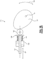
- Cam devices such as those used in internal combustion engines to actuate valve position, use a mechanism by which the rotation of the cam is converted into (axial) translation of a follower.
- these are spring-closed cams, where the outer surface of the rotating oblong cam displaces and pushes the follower away from the cam against a spring, with the spring then closing the valve when the cam no longer displaces the follower.
- An example spring-closed cam with an axial follower is shown in Figure 1B , with a mechanism 120 having a cam 121, a spring 124, and a follower 122.
- Follower 122 has a roller 123 and a spring retainer 128, with spring 124 being compressed between spring retainer 128 and a fixed surface 129.
- cam 121 rotates in a direction 126 about an axle 125, the surface of cam 121 is pressed against roller 123 by the rotation of cam 121 or by the force exerted by spring 124, resulting in translation of follower 122 in a direction 127.
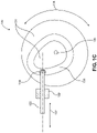
- Form-closed cams have a groove, track, or slot which contacts the follower on two surfaces, allowing the rotating cam to both push the follower away from the cam at one portion of the cam's rotation cycle and pull the follower toward the cam at another portion of the cam's rotation.
- An example form-closed cam with a translating follower is shown in Figure 1C , with a mechanism 130 having a cam 131 and a follower 132.
- Cam 131 has track a 138
- follower 132 has a roller 133, with roller 133 being constrained by track 138.
- cam 131 rotates in a direction 136 about an axle 135, the inner and outer surfaces of track 138 are pressed against roller 133 by the rotation of cam 131, resulting in translation of follower 132 relative to a fixed surface 139 in a direction 137.
- form-closed cams with translating followers are typically used to impart follower translation as a result of cam rotational movement, conversely, force exerted by the follower on the cam can also be used to affect the rotation/position of the cam.
- An actuator 200 includes a ball screw assembly 201, an electric motor assembly 202, a yoke guide 209, and a joint cam 203.
- Ball screw assembly 201 has a ball screw 204, a ball nut 205, and a yoke 206, with yoke 206 being connected to ball nut 205.
- Yoke 206 has a cam roller 208 at a yoke roller assembly 207.
- Joint cam 203 has a cam body 220 and a cam roller track 222, with joint cam 203 pivoting about a joint bearing 212 at a joint 213.
- Cam roller 208 of yoke roller assembly 207 is constrained within, and can travel along, cam roller track 222.
- Yoke 206 is constrained within, and can travel along, yoke guide 209 at yoke roller assembly 207.
- Yoke guide 209 is connected to a ball screw housing 217 and electric motor assembly 202, and the position of joint bearing 212 at joint 213 is fixed relative to yoke guide 209, ball screw housing 217, and electric motor assembly 202.
- a bearing 216 is attached to ball screw 204 and a ball screw mount 218, with ball screw mount 218 being profiled such as to allow yoke 206 to translate past ball screw mount 218.
- Ball screw mount 218 is fixed relative to yoke guide 209 and ball screw housing 217.
- Actuator 200 effects movement of joint cam 203 about joint 213 as an electric motor 210 rotates a shaft 211, causing rotation of the attached ball screw 204, and resulting in translation of ball nut 205 and yoke 206 in a direction 214.
- cam roller 208 applies force to cam body 220 along cam roller track 222, causing movement of cam roller 208 along cam roller track 222 and rotation of joint cam 203 in a direction 215 at joint bearing 212.
- the profile of the actuator cam allows for varying degrees of mechanical advantage to be generated in a low-bulk actuator device and for this mechanical advantage to be varied over the actuator stroke (e.g., the actuator can have a 1.5-inch moment arm at full extension and a 0.75-inch moment arm at full flex). Alternatively, the actuator can produce a consistent mechanical advantage over the entire actuator stroke.
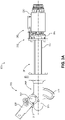
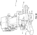
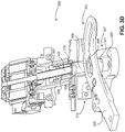
- an actuator 300 including an electric motor assembly 302, a load cell assembly 332, a joint cam 303, an outer yoke guide 309, an inner yoke guide 329, and a ball screw assembly 301.
- Electric motor assembly 302 has an electric motor 310, a shaft 311, and a motor housing 330.
- Load cell assembly 332 has a load cell 333 and a load cell housing 334.
- Joint cam 303 has a cam body 320 and a cam roller track 322, with joint cam 303 pivoting about a joint bearing 312 at a joint 313.
- Ball screw assembly 301 has a ball screw 304, a ball nut 305, and a yoke 306, with yoke 306 being connected to ball nut 305 and having a yoke roller assembly 307.
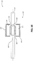
- Yoke roller assembly 307 shown in a simplified sectional view in Figure 3E , is comprised of a cam roller 308, an inner guide roller 341, and an outer guide roller 342.
- Cam roller 308 is constrained within, and can travel along, cam roller track 322, as best seen in Figure 3B .
- Yoke 306 is constrained within, and can travel along outer yoke guide 309 and inner yoke guide 329 at yoke roller assembly 307, with outer guide roller 342 and inner guide roller 341 of yoke 306 being constrained within outer yoke guide 309 and inner yoke guide 329, respectively.
- Outer yoke guide 309 and inner yoke guide 329 are connected to a ball screw housing 317, which is connected to load cell assembly 332, which is connected to electric motor assembly 302.
- the position of joint bearing 312 at joint 313 is fixed relative to outer yoke guide 309, inner yoke guide 329, ball screw housing 317, load cell assembly 332, and electric motor assembly 302.
- a bearing 316 is attached to ball screw 304 and a ball screw mount 318, with ball screw mount 318 being profiled such as to allow yoke 306 to translate past ball screw mount 318.
- Ball screw mount 318 is fixed relative to outer yoke guide 309, inner yoke guide 329, and ball screw housing 317.
- Load cell assembly 332 is configured such that load cell 333 can detect changes in compressive force at load cell 333 that result from activation of the actuator mechanism and/or movement of the joint cam, with load cell assembly 332 being in communication with the exoskeleton control system.
- the load cell was the FUTEK ® (Irvine, CA) Model LTH300, a donut load cell, which detects compressive force, although the load cell can be configured, as in this embodiment, to detect bidirectional force (as described in FUTEK ® Doc. No. EL1058 for Model LTH300 / L2760 Series).
- Exoskeleton 401 includes a torso structure 402, an exoskeleton control system 421, a rear support structure 403, a waist structure 404, a hip actuator 350, a hip joint 413, a thigh support 405, a knee joint 407, a shank support 409, an ankle joint 410, and a boot 411.
- Exoskeleton 401 is coupled to a torso 422 and a waist 423 of person 400 by torso structure 402 and waist structure 404.
- Exoskeleton 401 is coupled to a leg 414 of person 400 by a thigh coupler 406 and a shank coupler 408 and to a foot 416 of person 400 by boot 411.
- Exoskeleton control system 421 is in communication with actuator 350, allowing exoskeleton control system 421 to activate an electric motor assembly 352 and apply rotational force to a joint cam 353 about a joint bearing 362 at hip joint 413. The force from joint cam 353 is transmitted to thigh support 405 of exoskeleton 401. In this way, actuator 350 can apply force to and affect the position of hip joint 413 of exoskeleton 401.
- a load cell assembly 382 is in communication with exoskeleton control system 421, allowing exoskeleton control system 421 to better coordinate the application of force at and movement of actuator 350 and joint 413.
- the components of the actuator are placed differently on the exoskeleton structure.
- the actuator is mounted in alternate positions or effects movement of other exoskeleton joints, including, but not limited to, the knee, ankle, or elbow.
- the profile of the cam roller track is modified so as to provide differential mechanical advantage, by changing the moment arm of the cam to the ball screw drive mechanism at various joint positions.
- bellows completely or partially enclose ball screw mechanism, roller, and/or cam working surfaces to prevent dust or grit contamination of the actuator mechanism.
- this exoskeleton provides power to the joints of the exoskeleton and wearer to assist in activities such as walking. If this exoskeleton were equipped with the device of the primary embodiment, the bulk of the exoskeleton hips would be reduced, allowing the person to more easily maneuver the exoskeleton in tight places, such as getting into and out of a car.
- the primary embodiment consider a soldier wearing an armored exoskeleton in a combat environment, with this exoskeleton providing power to the joints of the exoskeleton that are involved in exoskeleton walking, and with the exoskeleton structure supporting the weight of armor. If this exoskeleton were equipped with the device of the primary embodiment, the reduced bulk of the exoskeleton at the hips would reduce the probability that brush or debris would snag on the exoskeleton during movement, improving mobility in constricted spaces. The reduced actuator bulk can also allow the soldier to better utilize cover, as the solider would be able to get closer to walls, objects, or the ground.
- An in-line slider crank linkage mechanism is a device that can convert straight-line motion to rotary motion (e.g., the pistons and crankshaft of an internal combustion engine) or, alternatively, convert rotary motion to straight-line motion (e.g., the electric motor and piston in a reciprocating pump).
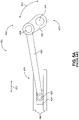
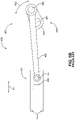
- a simplified example of in-line slider crank linkage is shown in Figures 5A and 5B , with a slider crank linkage 450 including a slider assembly 451 and a linkage crank assembly 452.
- Slider assembly 451 has a slider 454, a slider guide 455, and a slider joint 457
- linkage crank assembly 452 has a linkage 456, a crank 459, a crank joint 458, and an axle 460.
- slider 454 The movement of slider 454 is restricted by slider guide 455, allowing only translation of slider 454 in a direction 461.
- the movement of crank 459 is restricted by axle 460 to rotation about revolute joint 453 in a direction 462.
- Slider 454 is rotatably connected to linkage 456 at slider joint 457, and linkage 456 is rotatably connected to crank 459 by crank joint 458.
- slider 454 applies force to linkage 456, and linkage 456 transfers force to crank 459, resulting in rotation of crank 459 about revolute joint 453 in direction 462.
- the second embodiment of the present invention is represented in Figures 6A-G .
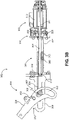
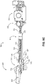
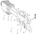
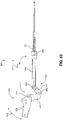
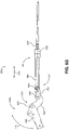
- the device of the second embodiment is shown, with an actuator 500 including an electric motor 502, a load cell assembly 532, a joint crank-linkage assembly 503, an outer yoke guide 509, an inner yoke guide 529, and a ball screw assembly 501.
- Joint crank-linkage assembly 503 has a joint crank 520, a linkage 551, and a linkage bearing 552, with joint crank 520 pivoting about a joint bearing 512 at joint 513.
- the axis of rotation of joint 513 passes through and is fixed relative to outer yoke guide 509 and inner yoke guide 529.
- Joint crank 520 is rotatably connected to linkage 551 at linkage bearing 552.
- Ball screw assembly 501 has a ball screw 504, a ball nut 505, and a yoke 506, with yoke 506 being connected to ball nut 505 and having a yoke roller assembly 507.
- Yoke roller assembly 507 is comprised of a yoke-linkage bearing and axle 508, an inner guide roller 541, and an outer guide roller 542.
- Yoke 506 is rotatably connected to linkage 551 by yoke-linkage bearing and axle 508.
- Yoke 506 is constrained within, and can travel along, outer yoke guide 509 and inner yoke guide 529, with inner guide roller 541 and outer guide roller 542 of yoke 506 being constrained within inner yoke guide 529 and outer yoke guide 509, respectively.
- Outer yoke guide 509 and inner yoke guide 529 are connected to a ball screw housing 517, which is connected to load cell assembly 532, which is connected electric motor assembly 502.
- the position of joint bearing 512 at joint 513 is fixed relative to outer yoke guide 509, inner yoke guide 529, ball screw housing 517, load cell assembly 532, and electric motor 502.
- a bearing 516 is attached to ball screw 504 and a ball screw mount 518, with ball screw mount 518 being profiled such as to allow yoke 506 to translate past ball screw mount 518.
- Ball screw mount 518 is fixed relative to outer yoke guide 509, inner yoke guide 529, and ball screw housing 517.
- Load cell assembly 532 is configured such that a load cell 533 can detect changes in compressive force at load cell 533 that result from activation of the actuator mechanism and/or movement of the joint cam, with load cell assembly 532 being in communication with the exoskeleton control system.
- the load cell was the FUTEK ® (Irvine, CA) Model LTH300, a donut load cell, which detects compressive force, although the load cell can be configured, as in this embodiment, to detect bidirectional force (as described in FUTEK ® Doc No. EL1058 for Model LTH300 / L2760 Series).
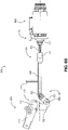
- FIG. 6E-G a simplified view of the device of the second embodiment is shown, allowing the mechanism of the actuator to be illustrated.
- yoke 506 applies force to linkage 551, and linkage 551 transfers this force to joint crank 520.
- the force applied to joint crank 520 results in rotation of joint crank 520 about joint 513 in a direction 515.
- bidirectional translation of ball nut 505 can effect bidirectional rotation of joint 513.
- Actuator 500 can be configured to provide a variable mechanical advantage over the actuator stroke or a consistent mechanical advantage over the entire actuator stroke.
- bellows completely or partially enclose ball screw mechanism, roller, linkage, and/or crank working surfaces to prevent dust or grit contamination of the actuator mechanism.
- the actuator is mounted at various exoskeleton positions, or effects the movement of various exoskeleton joints, including, but not limited to, the hip, knee, ankle, or elbow.
- this exoskeleton provides power to the joints of the exoskeleton and wearer to assist in activities such as walking or standing for extended periods of time. If this exoskeleton were equipped with the device of the second embodiment, the bulk of the exoskeleton joints would be reduced, allowing the person to more easily maneuver the exoskeleton in tight workspaces or in a crowd of people, and allowing the exoskeleton wearer to use a workspace that may be unsuitable for disabled worker access.
- additional sensors can be in communication with the exoskeleton control system, allowing the exoskeleton to respond to the user.
- a ball nut with recirculating balls is replaced with a rolling ring drive
- the ball screw is replaced with a "threadless ball screw" rotating rod drive mechanism.
- the bearings are set at an angle to the threadless rod, with this angle determining the direction and rate of linear motion of the rolling ring drive per revolution of the rod, as driven by the motor.
- various types of sensors are used to determine the position of the actuator or joint.
- various additional types of sensors are used to detect the forces exerted upon the joint.
- the load cell is located between the motor and the ball screw, as illustrated. In other embodiments, the load cell is integrated into the ball nut or yoke.
- the present invention provides a device for use in human exoskeletons that allows for the application of bidirectional force upon an exoskeleton joint, effecting bidirectional movement of the joint, with this device being located away from the joint.
- the device is highly efficient at the transfer of force from an electrical motor, or other power source, to the joint, minimizing energy consumption and/or maximizing force applied to the joint.
- the device is low profile and adds little bulk at the joint being powered.
- the device is capable of generating substantial mechanical advantage in a small space.
- the device incorporates a robust and simple system for force sensing, allowing the exoskeleton control system to accurately control the position of and the force applied to the joint.
- the device contains no failure-prone components (e.g., tensile members), allowing for improved exoskeleton wearer safety. While certain preferred embodiments of the present invention have been set forth, it should be understood that various changes or modifications could be made without departing from the scope of the present invention as laid out in the following claims.
Landscapes
- Engineering & Computer Science (AREA)
- Mechanical Engineering (AREA)
- Robotics (AREA)
- General Engineering & Computer Science (AREA)
- Health & Medical Sciences (AREA)
- Life Sciences & Earth Sciences (AREA)
- Physical Education & Sports Medicine (AREA)
- Rehabilitation Therapy (AREA)
- Pain & Pain Management (AREA)
- Animal Behavior & Ethology (AREA)
- General Health & Medical Sciences (AREA)
- Public Health (AREA)
- Veterinary Medicine (AREA)
- Epidemiology (AREA)
- Manipulator (AREA)
- Transmission Devices (AREA)
Claims (9)
- Exoskelett (401), umfassend:eine erste Stütze (405), die ausgelegt ist, um mit einem Träger des Exoskeletts (401) gekoppelt zu sein;eine zweite Stütze (403), die ausgelegt ist, um mit dem Träger gekoppelt zu sein;ein Gelenk (413), das die erste und die zweite Stütze (405, 403) verbindet, wobei das Gelenk (413) ausgelegt ist, um relative Rotation zwischen der ersten und der zweiten Stütze (405, 403) zu gestatten; undeinen Aktor (500), der ausgelegt ist, um relative Rotation zwischen der ersten und der zweiten Stütze bei dem Gelenk (413) zu veranlassen, wobei der Aktor (500) Folgendes beinhaltet:einen Motor (502);eine Kugelschraube (504), die mit dem Motor (502) gekoppelt ist;eine Kugelmutter (505), die mit der Kugelschraube (504) gekoppelt ist; undein Joch (506), das mit der Kugelmutter (505) gekoppelt ist, wobei der Motor (502) ausgelegt ist, um Rotation der Kugelschraube (504) zu veranlassen, die Kugelschraube (504) ausgelegt ist, um Verschiebung der Kugelmutter (505) entlang der Kugelschraube (504) während Rotation der Kugelschraube (504) zu veranlassen, und die Kugelmutter (505) ausgelegt ist, um Verschiebung des Jochs (506) während Verschiebung der Kugelmutter zu veranlassen; undein Verbindungsstück (551), das mit dem Joch (506) gekoppelt ist, und eine Gelenkkurbel (520), die mit dem Verbindungsstück (551) gekoppelt ist, wobei das Joch (506) an der Kugelmutter (505) befestigt ist und ausgelegt ist, um als ein Verschiebungsgleiter zu agieren, um Bewegung des Verbindungsstücks (551) während Verschiebung des Jochs (506) zu veranlassen, und die Gelenkkurbel (520) derart ausgelegt ist, dass Bewegung des Verbindungsstücks (551) Rotation der Gelenkkurbel (520) um das Gelenk (413) veranlasst, wodurch relative Rotation zwischen der ersten und der zweiten Stütze bei dem Gelenk (413) veranlasst wird.
- Exoskelett nach Anspruch 1, wobei der Aktor (500) weiter eine Jochführung (529) beinhaltet, die ausgelegt ist, um Verschiebung des Jochs (506) zu führen.
- Exoskelett nach Anspruch 1, wobei der Aktor (500) weiter eine Lastzelle (333) beinhaltet, die ausgelegt ist, um Kraftänderungen bei der Lastzelle (333) zu erfassen, die aus Aktivierung des Aktors (500) oder Bewegung der Gelenkkurbel (520) resultieren.
- Exoskelett nach Anspruch 3, wobei die Lastzelle (333) zwischen dem Motor (502) und der Kugelschraube (504) liegt.
- Exoskelett nach Anspruch 1, wobei der Aktor (500) das Verbindungsstück (551) und die Gelenkkurbel (520) beinhaltet.
- Exoskelett nach Anspruch 5, wobei:der Aktor (500) weiter ein Joch-Verbindungsstück-Lager (508) und ein Verbindungsstück-Kurbel-Lager beinhaltet;das Verbindungsstück (551) rotierbar mit dem Joch (506) durch das Joch-Verbindungsstück-Lager (508) gekoppelt ist; unddie Gelenkkurbel (520) rotierbar mit dem Verbindungsstück (551) durch das Verbindungsstück-Kurbel-Lager (508) gekoppelt ist.
- Verfahren zum Betätigen eines Gelenks (413) eines Exoskeletts (401), das eine erste Stütze (405), die ausgelegt ist, um mit einem Träger des Exoskeletts (401) gekoppelt zu sein,
eine zweite Stütze (403), die ausgelegt ist, um mit dem Träger gekoppelt zu sein, und einen Aktor (500) beinhaltet, wobei das Gelenk (413) die erste und die zweite Stütze (405, 403) verbindet, das Gelenk (413) ausgelegt ist, um relative Rotation zwischen der ersten und der zweiten Stütze (405, 403) zu gestatten, und der Aktor (500) ausgelegt ist, um relative Rotation zwischen der ersten und der zweiten Stütze bei dem Gelenk (413) zu veranlassen, wobei das Verfahren Folgendes umfasst:Veranlassen von Rotation einer Kugelschraube (504) mit einem Motor (502), wobei die Kugelschraube (504) mit dem Motor (502) gekoppelt ist;Veranlassen von Verschiebung einer Kugelmutter (505) entlang der Kugelschraube (504) durch Rotieren der Kugelschraube (504), wobei die Kugelmutter (505) mit der Kugelschraube (504) gekoppelt ist; undVeranlassen von Verschiebung eines Jochs (506) durch Verschieben der Kugelmutter (505), wobei das Joch (506) an der Kugelmutter (505) befestigt ist; undVeranlassen von Bewegung eines Verbindungsstücks (551) durch Verschieben des Jochs (506), wobei das Joch (506) als ein Verschiebungsgleiter agiert und wobei das Verbindungsstück (551) mit dem Joch (506) gekoppelt ist, und Veranlassen von Rotation einer Gelenkkurbel (520) um das Gelenk (413) durch Bewegen des Verbindungsstücks (551), wobei die Gelenkkurbel (520) mit dem Verbindungsstück (551) gekoppelt ist, wodurch relative Rotation zwischen der ersten und der zweiten Stütze (405, 403) bei dem Gelenk (413) veranlasst wird. - Verfahren nach Anspruch 7, weiter umfassend Erzeugen von variabler mechanischer Kraftverstärkung über den Verschiebungsbereich der Kugelmutter (505) entlang der Kugelschraube (504).
- Verfahren nach Anspruch 7, umfassend Veranlassen von Bewegung des Verbindungsstücks (551) durch Verschieben des Jochs (506), und Veranlassen von Rotation der Gelenkkurbel (520) um das Gelenk (413) durch Bewegen des Verbindungsstücks (551).
Applications Claiming Priority (2)
| Application Number | Priority Date | Filing Date | Title |
|---|---|---|---|
| US201762468497P | 2017-03-08 | 2017-03-08 | |
| PCT/US2018/021298 WO2018165261A1 (en) | 2017-03-08 | 2018-03-07 | Actuator devices for human exoskeleton joints |
Publications (3)
| Publication Number | Publication Date |
|---|---|
| EP3592177A1 EP3592177A1 (de) | 2020-01-15 |
| EP3592177A4 EP3592177A4 (de) | 2021-08-04 |
| EP3592177B1 true EP3592177B1 (de) | 2022-11-16 |
Family
ID=63448009
Family Applications (1)
| Application Number | Title | Priority Date | Filing Date |
|---|---|---|---|
| EP18763586.7A Active EP3592177B1 (de) | 2017-03-08 | 2018-03-07 | Aktuatorvorrichtungen für gelenke eines menschlichen exoskeletts |
Country Status (4)
| Country | Link |
|---|---|
| US (1) | US11673253B2 (de) |
| EP (1) | EP3592177B1 (de) |
| PL (1) | PL3592177T3 (de) |
| WO (1) | WO2018165261A1 (de) |
Families Citing this family (18)
| Publication number | Priority date | Publication date | Assignee | Title |
|---|---|---|---|---|
| KR102631409B1 (ko) * | 2018-02-20 | 2024-01-31 | 삼성전자주식회사 | 운동 보조 장치 |
| CN111376308B (zh) * | 2018-12-30 | 2022-09-20 | 中国科学院沈阳自动化研究所 | 球窝式两自由度变刚度机器人关节 |
| CA3158141A1 (en) | 2019-11-12 | 2021-05-20 | Luke Mooney | Lower limb exoskeleton |
| CN111390874A (zh) * | 2020-03-30 | 2020-07-10 | 北京海益同展信息科技有限公司 | 一种外骨骼结构 |
| US11298287B2 (en) | 2020-06-02 | 2022-04-12 | Dephy, Inc. | Systems and methods for a compressed controller for an active exoskeleton |
| US11148279B1 (en) | 2020-06-04 | 2021-10-19 | Dephy, Inc. | Customized configuration for an exoskeleton controller |
| US11147733B1 (en) | 2020-06-04 | 2021-10-19 | Dephy, Inc. | Systems and methods for bilateral wireless communication |
| US11389367B2 (en) * | 2020-06-05 | 2022-07-19 | Dephy, Inc. | Real-time feedback-based optimization of an exoskeleton |
| EP4175796A4 (de) * | 2020-07-06 | 2024-08-07 | XYZ Robotics Inc. | Strukturelle wägezellengehäuse zur ummantelung von sensoren in robotersystemen |
| US12090069B2 (en) | 2020-08-25 | 2024-09-17 | Dephy, Inc. | Systems and methods for a water resistant active exoskeleton |
| US11173093B1 (en) | 2020-09-16 | 2021-11-16 | Dephy, Inc. | Systems and methods for an active exoskeleton with local battery |
| CN112605979B (zh) * | 2020-12-14 | 2024-07-19 | 何学谦 | 一种外骨骼 |
| CN112927731B (zh) * | 2021-01-27 | 2021-12-07 | 深圳冠兰达电子科技有限公司 | 一种方便调节方向的激光播放器 |
| CN114147763B (zh) * | 2021-04-05 | 2025-12-12 | 新加坡国立大学 | 辅助人体躯干的装置 |
| IT202100011273A1 (it) * | 2021-05-04 | 2022-11-04 | Fondazione St Italiano Tecnologia | Bilanciamento elastico di carichi in un esoscheletro |
| US20240075612A1 (en) | 2022-09-02 | 2024-03-07 | Motion Augmented LLC | Modular motor units and methods for making the same for active-passive robotic exoskeleton systems |
| FR3143699B1 (fr) * | 2022-12-16 | 2024-11-29 | Commissariat Energie Atomique | Actionneur à vis-écrou et sortie rotative à position réglable |
| FR3143700B1 (fr) * | 2022-12-16 | 2024-11-29 | Commissariat Energie Atomique | Actionneur à vis/écrou à compacité améliorée |
Family Cites Families (13)
| Publication number | Priority date | Publication date | Assignee | Title |
|---|---|---|---|---|
| US4843921A (en) | 1988-04-18 | 1989-07-04 | Kremer Stephen R | Twisted cord actuator |
| US5458560A (en) * | 1993-09-03 | 1995-10-17 | Jace Systems, Inc. | Continuous passive motion device for a wrist |
| US20070123997A1 (en) | 2005-03-31 | 2007-05-31 | Massachusetts Institute Of Technology | Exoskeletons for running and walking |
| KR101631538B1 (ko) | 2009-09-18 | 2016-06-21 | 삼성전자 주식회사 | 로봇용 액추에이터 및 이를 포함하는 인간형 로봇 |
| WO2014093470A1 (en) * | 2012-12-11 | 2014-06-19 | Ekso Bionics, Inc. | Reconfigurable exoskeleton |
| ES2562340B1 (es) | 2014-09-03 | 2016-12-07 | Universitat Politècnica De Catalunya | Dispositivo de motorización para órtesis activa |
| US10449105B2 (en) | 2014-10-26 | 2019-10-22 | Springactive, Inc. | System and method of bidirectional compliant joint torque actuation |
| AU2015360683B2 (en) * | 2014-12-08 | 2019-11-21 | Rehabilitation Institute Of Chicago | Powered and passive assistive device and related methods |
| FR3034660B1 (fr) * | 2015-04-07 | 2022-06-10 | Wandercraft | Exosquelette comprenant une liaison mecanique de cheville avec deux axes de pivotement |
| US10456286B2 (en) * | 2015-09-17 | 2019-10-29 | The Regents Of The University Of California | Torque-compensating assistive wrist braces |
| ITUA20162490A1 (it) * | 2016-04-11 | 2017-10-11 | Fondazione St Italiano Tecnologia | Attuatore per esoscheletro |
| US11191653B2 (en) * | 2016-11-03 | 2021-12-07 | University Of New Brunswick | Powered lower limb devices and methods of control thereof |
| US10253855B2 (en) * | 2016-12-15 | 2019-04-09 | Boston Dynamics, Inc. | Screw actuator for a legged robot |
-
2018
- 2018-03-07 PL PL18763586.7T patent/PL3592177T3/pl unknown
- 2018-03-07 EP EP18763586.7A patent/EP3592177B1/de active Active
- 2018-03-07 WO PCT/US2018/021298 patent/WO2018165261A1/en not_active Ceased
- 2018-03-07 US US16/491,091 patent/US11673253B2/en active Active
Also Published As
| Publication number | Publication date |
|---|---|
| US11673253B2 (en) | 2023-06-13 |
| PL3592177T3 (pl) | 2023-01-30 |
| EP3592177A4 (de) | 2021-08-04 |
| EP3592177A1 (de) | 2020-01-15 |
| US20200011406A1 (en) | 2020-01-09 |
| WO2018165261A1 (en) | 2018-09-13 |
Similar Documents
| Publication | Publication Date | Title |
|---|---|---|
| EP3592177B1 (de) | Aktuatorvorrichtungen für gelenke eines menschlichen exoskeletts | |
| CN107343843B (zh) | 外骨骼、外骨骼关节致动器及用于造成外骨骼的移动的方法 | |
| Lee et al. | Lower limb exoskeleton systems—overview | |
| Haghshenas-Jaryani et al. | A pilot study on the design and validation of a hybrid exoskeleton robotic device for hand rehabilitation | |
| Low | Robot-assisted gait rehabilitation: From exoskeletons to gait systems | |
| Niyetkaliyev et al. | Review on design and control aspects of robotic shoulder rehabilitation orthoses | |
| Sui et al. | Design of a wearable upper-limb exoskeleton for activities assistance of daily living | |
| Hussain et al. | An intrinsically compliant robotic orthosis for treadmill training | |
| KR101828256B1 (ko) | 멀티링크 무릎관절을 구비한 하지 로봇 및 그 제어 방법 | |
| Pylatiuk et al. | Design of a flexible fluidic actuation system for a hybrid elbow orthosis | |
| Islam et al. | Exoskeletons in upper limb rehabilitation: A review to find key challenges to improve functionality | |
| Lee et al. | Technical trend of the lower limb exoskeleton system for the performance enhancement | |
| Hasan et al. | State of the art technologies for exoskeleton human lower extremity rehabilitation robots | |
| Gandolla et al. | BRIDGE—behavioural reaching interfaces during daily antigravity activities through upper limb exoskeleton: preliminary results | |
| Choi et al. | Development of adjustable knee assist device for wearable robot based on linkage and rolling joint | |
| Jarrassé et al. | Design and acceptability assessment of a new reversible orthosis | |
| Rodríguez-Jorge et al. | Biomechanics-informed mechatronics design of comfort-centered portable hip exoskeleton: actuator, wearable interface, controller | |
| Han et al. | Research on a multimodal actuator-oriented power-assisted knee exoskeleton | |
| Buerger et al. | Rehabilitation robotics: adapting robot behavior to suit patient needs and abilities | |
| Alqahtani et al. | Exoskeletons for lower limb applications: A review | |
| Yang et al. | Simulation of exoskeleton ZMP during walking for balance control | |
| Schnieders et al. | A current review of human factors and ergonomic intervention with exoskeletons | |
| Song et al. | Improvement of upper extremity rehabilitation Robotic Exoskeleton, NREX | |
| Huang et al. | Design of a compliant joint actuator for lower-limb exoskeleton robot | |
| Park et al. | Low cost and light-weight multi-DOF exoskeleton for comprehensive upper limb rehabilitation |
Legal Events
| Date | Code | Title | Description |
|---|---|---|---|
| STAA | Information on the status of an ep patent application or granted ep patent |
Free format text: STATUS: THE INTERNATIONAL PUBLICATION HAS BEEN MADE |
|
| PUAI | Public reference made under article 153(3) epc to a published international application that has entered the european phase |
Free format text: ORIGINAL CODE: 0009012 |
|
| STAA | Information on the status of an ep patent application or granted ep patent |
Free format text: STATUS: REQUEST FOR EXAMINATION WAS MADE |
|
| 17P | Request for examination filed |
Effective date: 20191004 |
|
| AK | Designated contracting states |
Kind code of ref document: A1 Designated state(s): AL AT BE BG CH CY CZ DE DK EE ES FI FR GB GR HR HU IE IS IT LI LT LU LV MC MK MT NL NO PL PT RO RS SE SI SK SM TR |
|
| AX | Request for extension of the european patent |
Extension state: BA ME |
|
| DAV | Request for validation of the european patent (deleted) | ||
| DAX | Request for extension of the european patent (deleted) | ||
| RIC1 | Information provided on ipc code assigned before grant |
Ipc: A45F 3/08 20060101AFI20210128BHEP Ipc: B25J 9/00 20060101ALI20210128BHEP |
|
| A4 | Supplementary search report drawn up and despatched |
Effective date: 20210701 |
|
| RIC1 | Information provided on ipc code assigned before grant |
Ipc: A45F 3/08 20060101AFI20210625BHEP Ipc: B25J 9/00 20060101ALI20210625BHEP |
|
| GRAP | Despatch of communication of intention to grant a patent |
Free format text: ORIGINAL CODE: EPIDOSNIGR1 |
|
| STAA | Information on the status of an ep patent application or granted ep patent |
Free format text: STATUS: GRANT OF PATENT IS INTENDED |
|
| INTG | Intention to grant announced |
Effective date: 20220630 |
|
| GRAS | Grant fee paid |
Free format text: ORIGINAL CODE: EPIDOSNIGR3 |
|
| GRAA | (expected) grant |
Free format text: ORIGINAL CODE: 0009210 |
|
| STAA | Information on the status of an ep patent application or granted ep patent |
Free format text: STATUS: THE PATENT HAS BEEN GRANTED |
|
| AK | Designated contracting states |
Kind code of ref document: B1 Designated state(s): AL AT BE BG CH CY CZ DE DK EE ES FI FR GB GR HR HU IE IS IT LI LT LU LV MC MK MT NL NO PL PT RO RS SE SI SK SM TR |
|
| REG | Reference to a national code |
Ref country code: GB Ref legal event code: FG4D |
|
| REG | Reference to a national code |
Ref country code: CH Ref legal event code: EP |
|
| REG | Reference to a national code |
Ref country code: DE Ref legal event code: R096 Ref document number: 602018043150 Country of ref document: DE |
|
| REG | Reference to a national code |
Ref country code: IE Ref legal event code: FG4D |
|
| REG | Reference to a national code |
Ref country code: AT Ref legal event code: REF Ref document number: 1531221 Country of ref document: AT Kind code of ref document: T Effective date: 20221215 |
|
| REG | Reference to a national code |
Ref country code: LT Ref legal event code: MG9D |
|
| REG | Reference to a national code |
Ref country code: NL Ref legal event code: MP Effective date: 20221116 |
|
| REG | Reference to a national code |
Ref country code: AT Ref legal event code: MK05 Ref document number: 1531221 Country of ref document: AT Kind code of ref document: T Effective date: 20221116 |
|
| PG25 | Lapsed in a contracting state [announced via postgrant information from national office to epo] |
Ref country code: SE Free format text: LAPSE BECAUSE OF FAILURE TO SUBMIT A TRANSLATION OF THE DESCRIPTION OR TO PAY THE FEE WITHIN THE PRESCRIBED TIME-LIMIT Effective date: 20221116 Ref country code: PT Free format text: LAPSE BECAUSE OF FAILURE TO SUBMIT A TRANSLATION OF THE DESCRIPTION OR TO PAY THE FEE WITHIN THE PRESCRIBED TIME-LIMIT Effective date: 20230316 Ref country code: NO Free format text: LAPSE BECAUSE OF FAILURE TO SUBMIT A TRANSLATION OF THE DESCRIPTION OR TO PAY THE FEE WITHIN THE PRESCRIBED TIME-LIMIT Effective date: 20230216 Ref country code: LT Free format text: LAPSE BECAUSE OF FAILURE TO SUBMIT A TRANSLATION OF THE DESCRIPTION OR TO PAY THE FEE WITHIN THE PRESCRIBED TIME-LIMIT Effective date: 20221116 Ref country code: FI Free format text: LAPSE BECAUSE OF FAILURE TO SUBMIT A TRANSLATION OF THE DESCRIPTION OR TO PAY THE FEE WITHIN THE PRESCRIBED TIME-LIMIT Effective date: 20221116 Ref country code: ES Free format text: LAPSE BECAUSE OF FAILURE TO SUBMIT A TRANSLATION OF THE DESCRIPTION OR TO PAY THE FEE WITHIN THE PRESCRIBED TIME-LIMIT Effective date: 20221116 Ref country code: AT Free format text: LAPSE BECAUSE OF FAILURE TO SUBMIT A TRANSLATION OF THE DESCRIPTION OR TO PAY THE FEE WITHIN THE PRESCRIBED TIME-LIMIT Effective date: 20221116 |
|
| PG25 | Lapsed in a contracting state [announced via postgrant information from national office to epo] |
Ref country code: RS Free format text: LAPSE BECAUSE OF FAILURE TO SUBMIT A TRANSLATION OF THE DESCRIPTION OR TO PAY THE FEE WITHIN THE PRESCRIBED TIME-LIMIT Effective date: 20221116 Ref country code: LV Free format text: LAPSE BECAUSE OF FAILURE TO SUBMIT A TRANSLATION OF THE DESCRIPTION OR TO PAY THE FEE WITHIN THE PRESCRIBED TIME-LIMIT Effective date: 20221116 Ref country code: IS Free format text: LAPSE BECAUSE OF FAILURE TO SUBMIT A TRANSLATION OF THE DESCRIPTION OR TO PAY THE FEE WITHIN THE PRESCRIBED TIME-LIMIT Effective date: 20230316 Ref country code: HR Free format text: LAPSE BECAUSE OF FAILURE TO SUBMIT A TRANSLATION OF THE DESCRIPTION OR TO PAY THE FEE WITHIN THE PRESCRIBED TIME-LIMIT Effective date: 20221116 Ref country code: GR Free format text: LAPSE BECAUSE OF FAILURE TO SUBMIT A TRANSLATION OF THE DESCRIPTION OR TO PAY THE FEE WITHIN THE PRESCRIBED TIME-LIMIT Effective date: 20230217 |
|
| PG25 | Lapsed in a contracting state [announced via postgrant information from national office to epo] |
Ref country code: NL Free format text: LAPSE BECAUSE OF FAILURE TO SUBMIT A TRANSLATION OF THE DESCRIPTION OR TO PAY THE FEE WITHIN THE PRESCRIBED TIME-LIMIT Effective date: 20221116 |
|
| P01 | Opt-out of the competence of the unified patent court (upc) registered |
Effective date: 20230525 |
|
| PG25 | Lapsed in a contracting state [announced via postgrant information from national office to epo] |
Ref country code: SM Free format text: LAPSE BECAUSE OF FAILURE TO SUBMIT A TRANSLATION OF THE DESCRIPTION OR TO PAY THE FEE WITHIN THE PRESCRIBED TIME-LIMIT Effective date: 20221116 Ref country code: RO Free format text: LAPSE BECAUSE OF FAILURE TO SUBMIT A TRANSLATION OF THE DESCRIPTION OR TO PAY THE FEE WITHIN THE PRESCRIBED TIME-LIMIT Effective date: 20221116 Ref country code: EE Free format text: LAPSE BECAUSE OF FAILURE TO SUBMIT A TRANSLATION OF THE DESCRIPTION OR TO PAY THE FEE WITHIN THE PRESCRIBED TIME-LIMIT Effective date: 20221116 Ref country code: DK Free format text: LAPSE BECAUSE OF FAILURE TO SUBMIT A TRANSLATION OF THE DESCRIPTION OR TO PAY THE FEE WITHIN THE PRESCRIBED TIME-LIMIT Effective date: 20221116 Ref country code: CZ Free format text: LAPSE BECAUSE OF FAILURE TO SUBMIT A TRANSLATION OF THE DESCRIPTION OR TO PAY THE FEE WITHIN THE PRESCRIBED TIME-LIMIT Effective date: 20221116 |
|
| REG | Reference to a national code |
Ref country code: DE Ref legal event code: R097 Ref document number: 602018043150 Country of ref document: DE |
|
| PG25 | Lapsed in a contracting state [announced via postgrant information from national office to epo] |
Ref country code: SK Free format text: LAPSE BECAUSE OF FAILURE TO SUBMIT A TRANSLATION OF THE DESCRIPTION OR TO PAY THE FEE WITHIN THE PRESCRIBED TIME-LIMIT Effective date: 20221116 Ref country code: AL Free format text: LAPSE BECAUSE OF FAILURE TO SUBMIT A TRANSLATION OF THE DESCRIPTION OR TO PAY THE FEE WITHIN THE PRESCRIBED TIME-LIMIT Effective date: 20221116 |
|
| PLBE | No opposition filed within time limit |
Free format text: ORIGINAL CODE: 0009261 |
|
| STAA | Information on the status of an ep patent application or granted ep patent |
Free format text: STATUS: NO OPPOSITION FILED WITHIN TIME LIMIT |
|
| 26N | No opposition filed |
Effective date: 20230817 |
|
| PG25 | Lapsed in a contracting state [announced via postgrant information from national office to epo] |
Ref country code: MC Free format text: LAPSE BECAUSE OF FAILURE TO SUBMIT A TRANSLATION OF THE DESCRIPTION OR TO PAY THE FEE WITHIN THE PRESCRIBED TIME-LIMIT Effective date: 20221116 |
|
| REG | Reference to a national code |
Ref country code: CH Ref legal event code: PL |
|
| GBPC | Gb: european patent ceased through non-payment of renewal fee |
Effective date: 20230307 |
|
| PG25 | Lapsed in a contracting state [announced via postgrant information from national office to epo] |
Ref country code: SI Free format text: LAPSE BECAUSE OF FAILURE TO SUBMIT A TRANSLATION OF THE DESCRIPTION OR TO PAY THE FEE WITHIN THE PRESCRIBED TIME-LIMIT Effective date: 20221116 |
|
| REG | Reference to a national code |
Ref country code: BE Ref legal event code: MM Effective date: 20230331 |
|
| PG25 | Lapsed in a contracting state [announced via postgrant information from national office to epo] |
Ref country code: LU Free format text: LAPSE BECAUSE OF NON-PAYMENT OF DUE FEES Effective date: 20230307 |
|
| REG | Reference to a national code |
Ref country code: IE Ref legal event code: MM4A |
|
| PG25 | Lapsed in a contracting state [announced via postgrant information from national office to epo] |
Ref country code: GB Free format text: LAPSE BECAUSE OF NON-PAYMENT OF DUE FEES Effective date: 20230307 |
|
| PG25 | Lapsed in a contracting state [announced via postgrant information from national office to epo] |
Ref country code: LI Free format text: LAPSE BECAUSE OF NON-PAYMENT OF DUE FEES Effective date: 20230331 Ref country code: IE Free format text: LAPSE BECAUSE OF NON-PAYMENT OF DUE FEES Effective date: 20230307 Ref country code: GB Free format text: LAPSE BECAUSE OF NON-PAYMENT OF DUE FEES Effective date: 20230307 Ref country code: CH Free format text: LAPSE BECAUSE OF NON-PAYMENT OF DUE FEES Effective date: 20230331 |
|
| PG25 | Lapsed in a contracting state [announced via postgrant information from national office to epo] |
Ref country code: BE Free format text: LAPSE BECAUSE OF NON-PAYMENT OF DUE FEES Effective date: 20230331 |
|
| PG25 | Lapsed in a contracting state [announced via postgrant information from national office to epo] |
Ref country code: BG Free format text: LAPSE BECAUSE OF FAILURE TO SUBMIT A TRANSLATION OF THE DESCRIPTION OR TO PAY THE FEE WITHIN THE PRESCRIBED TIME-LIMIT Effective date: 20221116 |
|
| PG25 | Lapsed in a contracting state [announced via postgrant information from national office to epo] |
Ref country code: BG Free format text: LAPSE BECAUSE OF FAILURE TO SUBMIT A TRANSLATION OF THE DESCRIPTION OR TO PAY THE FEE WITHIN THE PRESCRIBED TIME-LIMIT Effective date: 20221116 |
|
| PGFP | Annual fee paid to national office [announced via postgrant information from national office to epo] |
Ref country code: DE Payment date: 20250318 Year of fee payment: 8 |
|
| PGFP | Annual fee paid to national office [announced via postgrant information from national office to epo] |
Ref country code: FR Payment date: 20250318 Year of fee payment: 8 Ref country code: PL Payment date: 20250225 Year of fee payment: 8 |
|
| PGFP | Annual fee paid to national office [announced via postgrant information from national office to epo] |
Ref country code: IT Payment date: 20250318 Year of fee payment: 8 |
|
| PG25 | Lapsed in a contracting state [announced via postgrant information from national office to epo] |
Ref country code: CY Free format text: LAPSE BECAUSE OF FAILURE TO SUBMIT A TRANSLATION OF THE DESCRIPTION OR TO PAY THE FEE WITHIN THE PRESCRIBED TIME-LIMIT; INVALID AB INITIO Effective date: 20180307 |
|
| PG25 | Lapsed in a contracting state [announced via postgrant information from national office to epo] |
Ref country code: HU Free format text: LAPSE BECAUSE OF FAILURE TO SUBMIT A TRANSLATION OF THE DESCRIPTION OR TO PAY THE FEE WITHIN THE PRESCRIBED TIME-LIMIT; INVALID AB INITIO Effective date: 20180307 |
|
| PG25 | Lapsed in a contracting state [announced via postgrant information from national office to epo] |
Ref country code: TR Free format text: LAPSE BECAUSE OF FAILURE TO SUBMIT A TRANSLATION OF THE DESCRIPTION OR TO PAY THE FEE WITHIN THE PRESCRIBED TIME-LIMIT Effective date: 20221116 |