EP3243564A1 - Dispositif et procede pour la realisation de reactions de precipitation par association d'au moins deux produits de depart - Google Patents
Dispositif et procede pour la realisation de reactions de precipitation par association d'au moins deux produits de depart Download PDFInfo
- Publication number
- EP3243564A1 EP3243564A1 EP16401041.5A EP16401041A EP3243564A1 EP 3243564 A1 EP3243564 A1 EP 3243564A1 EP 16401041 A EP16401041 A EP 16401041A EP 3243564 A1 EP3243564 A1 EP 3243564A1
- Authority
- EP
- European Patent Office
- Prior art keywords
- zone
- mixing
- mixing zone
- flow
- reaction product
- Prior art date
- Legal status (The legal status is an assumption and is not a legal conclusion. Google has not performed a legal analysis and makes no representation as to the accuracy of the status listed.)
- Granted
Links
- 238000001556 precipitation Methods 0.000 title claims abstract description 69
- 238000006243 chemical reaction Methods 0.000 title claims abstract description 31
- 238000000034 method Methods 0.000 title claims description 45
- 238000002156 mixing Methods 0.000 claims abstract description 167
- 239000012530 fluid Substances 0.000 claims abstract description 78
- 239000000047 product Substances 0.000 claims abstract description 67
- 239000007795 chemical reaction product Substances 0.000 claims abstract description 45
- 239000000203 mixture Substances 0.000 claims description 24
- 230000008569 process Effects 0.000 claims description 21
- 239000007858 starting material Substances 0.000 claims description 16
- 238000005191 phase separation Methods 0.000 claims description 9
- 239000000654 additive Substances 0.000 claims description 7
- 230000000996 additive effect Effects 0.000 claims description 5
- 239000000443 aerosol Substances 0.000 claims description 2
- 238000007599 discharging Methods 0.000 claims description 2
- 230000009474 immediate action Effects 0.000 claims description 2
- 239000002245 particle Substances 0.000 description 21
- XLYOFNOQVPJJNP-UHFFFAOYSA-N water Substances O XLYOFNOQVPJJNP-UHFFFAOYSA-N 0.000 description 13
- 239000007787 solid Substances 0.000 description 11
- TZCXTZWJZNENPQ-UHFFFAOYSA-L barium sulfate Chemical compound [Ba+2].[O-]S([O-])(=O)=O TZCXTZWJZNENPQ-UHFFFAOYSA-L 0.000 description 10
- 230000000694 effects Effects 0.000 description 9
- 239000012071 phase Substances 0.000 description 9
- 230000004888 barrier function Effects 0.000 description 8
- 229920002545 silicone oil Polymers 0.000 description 8
- 238000004519 manufacturing process Methods 0.000 description 7
- 230000021715 photosynthesis, light harvesting Effects 0.000 description 7
- QYCVHILLJSYYBD-UHFFFAOYSA-L copper;oxalate Chemical compound [Cu+2].[O-]C(=O)C([O-])=O QYCVHILLJSYYBD-UHFFFAOYSA-L 0.000 description 5
- 238000001499 laser induced fluorescence spectroscopy Methods 0.000 description 5
- 239000007788 liquid Substances 0.000 description 5
- 239000008346 aqueous phase Substances 0.000 description 4
- 230000015572 biosynthetic process Effects 0.000 description 4
- 230000000903 blocking effect Effects 0.000 description 4
- 239000000470 constituent Substances 0.000 description 4
- 230000007423 decrease Effects 0.000 description 4
- 238000011835 investigation Methods 0.000 description 4
- 239000000463 material Substances 0.000 description 4
- UBXAKNTVXQMEAG-UHFFFAOYSA-L strontium sulfate Chemical compound [Sr+2].[O-]S([O-])(=O)=O UBXAKNTVXQMEAG-UHFFFAOYSA-L 0.000 description 4
- 239000000126 substance Substances 0.000 description 4
- YXFVVABEGXRONW-UHFFFAOYSA-N Toluene Chemical compound CC1=CC=CC=C1 YXFVVABEGXRONW-UHFFFAOYSA-N 0.000 description 3
- 239000003054 catalyst Substances 0.000 description 3
- 238000009826 distribution Methods 0.000 description 3
- 238000002474 experimental method Methods 0.000 description 3
- 239000000543 intermediate Substances 0.000 description 3
- 239000007864 aqueous solution Substances 0.000 description 2
- 239000003795 chemical substances by application Substances 0.000 description 2
- 239000000975 dye Substances 0.000 description 2
- 239000007791 liquid phase Substances 0.000 description 2
- 239000004926 polymethyl methacrylate Substances 0.000 description 2
- 239000012429 reaction media Substances 0.000 description 2
- 238000005185 salting out Methods 0.000 description 2
- 238000004088 simulation Methods 0.000 description 2
- 239000000243 solution Substances 0.000 description 2
- 229920005372 Plexiglas® Polymers 0.000 description 1
- PMZURENOXWZQFD-UHFFFAOYSA-L Sodium Sulfate Chemical compound [Na+].[Na+].[O-]S([O-])(=O)=O PMZURENOXWZQFD-UHFFFAOYSA-L 0.000 description 1
- 230000001133 acceleration Effects 0.000 description 1
- 238000009825 accumulation Methods 0.000 description 1
- 239000004480 active ingredient Substances 0.000 description 1
- 239000003463 adsorbent Substances 0.000 description 1
- 238000000429 assembly Methods 0.000 description 1
- 230000000712 assembly Effects 0.000 description 1
- WDIHJSXYQDMJHN-UHFFFAOYSA-L barium chloride Chemical compound [Cl-].[Cl-].[Ba+2] WDIHJSXYQDMJHN-UHFFFAOYSA-L 0.000 description 1
- 229910001626 barium chloride Inorganic materials 0.000 description 1
- 238000004364 calculation method Methods 0.000 description 1
- 230000008859 change Effects 0.000 description 1
- 239000003153 chemical reaction reagent Substances 0.000 description 1
- 229910000365 copper sulfate Inorganic materials 0.000 description 1
- ARUVKPQLZAKDPS-UHFFFAOYSA-L copper(II) sulfate Chemical compound [Cu+2].[O-][S+2]([O-])([O-])[O-] ARUVKPQLZAKDPS-UHFFFAOYSA-L 0.000 description 1
- 239000013078 crystal Substances 0.000 description 1
- 230000003247 decreasing effect Effects 0.000 description 1
- 230000001419 dependent effect Effects 0.000 description 1
- 238000013461 design Methods 0.000 description 1
- 238000010790 dilution Methods 0.000 description 1
- 239000012895 dilution Substances 0.000 description 1
- 239000006185 dispersion Substances 0.000 description 1
- 238000004945 emulsification Methods 0.000 description 1
- 239000004744 fabric Substances 0.000 description 1
- 239000012467 final product Substances 0.000 description 1
- 239000007850 fluorescent dye Substances 0.000 description 1
- 230000005484 gravity Effects 0.000 description 1
- 230000002209 hydrophobic effect Effects 0.000 description 1
- 239000003317 industrial substance Substances 0.000 description 1
- 230000002452 interceptive effect Effects 0.000 description 1
- 238000005259 measurement Methods 0.000 description 1
- 238000012986 modification Methods 0.000 description 1
- 230000004048 modification Effects 0.000 description 1
- 239000002105 nanoparticle Substances 0.000 description 1
- 230000035515 penetration Effects 0.000 description 1
- 239000000049 pigment Substances 0.000 description 1
- 229920003229 poly(methyl methacrylate) Polymers 0.000 description 1
- 239000002244 precipitate Substances 0.000 description 1
- 230000000750 progressive effect Effects 0.000 description 1
- 230000001681 protective effect Effects 0.000 description 1
- 239000000700 radioactive tracer Substances 0.000 description 1
- 239000000376 reactant Substances 0.000 description 1
- 238000011084 recovery Methods 0.000 description 1
- 150000003839 salts Chemical class 0.000 description 1
- 238000000926 separation method Methods 0.000 description 1
- ZNCPFRVNHGOPAG-UHFFFAOYSA-L sodium oxalate Chemical compound [Na+].[Na+].[O-]C(=O)C([O-])=O ZNCPFRVNHGOPAG-UHFFFAOYSA-L 0.000 description 1
- 229940039790 sodium oxalate Drugs 0.000 description 1
- 229910052938 sodium sulfate Inorganic materials 0.000 description 1
- 235000011152 sodium sulphate Nutrition 0.000 description 1
- 238000007711 solidification Methods 0.000 description 1
- 230000008023 solidification Effects 0.000 description 1
- 238000004611 spectroscopical analysis Methods 0.000 description 1
- 230000000087 stabilizing effect Effects 0.000 description 1
- 239000004094 surface-active agent Substances 0.000 description 1
- 239000000725 suspension Substances 0.000 description 1
- 238000012360 testing method Methods 0.000 description 1
- 230000001052 transient effect Effects 0.000 description 1
- 238000012795 verification Methods 0.000 description 1
Images


Classifications
-
- B—PERFORMING OPERATIONS; TRANSPORTING
- B01—PHYSICAL OR CHEMICAL PROCESSES OR APPARATUS IN GENERAL
- B01J—CHEMICAL OR PHYSICAL PROCESSES, e.g. CATALYSIS OR COLLOID CHEMISTRY; THEIR RELEVANT APPARATUS
- B01J19/00—Chemical, physical or physico-chemical processes in general; Their relevant apparatus
- B01J19/26—Nozzle-type reactors, i.e. the distribution of the initial reactants within the reactor is effected by their introduction or injection through nozzles
-
- B—PERFORMING OPERATIONS; TRANSPORTING
- B01—PHYSICAL OR CHEMICAL PROCESSES OR APPARATUS IN GENERAL
- B01J—CHEMICAL OR PHYSICAL PROCESSES, e.g. CATALYSIS OR COLLOID CHEMISTRY; THEIR RELEVANT APPARATUS
- B01J19/00—Chemical, physical or physico-chemical processes in general; Their relevant apparatus
- B01J19/24—Stationary reactors without moving elements inside
- B01J19/2415—Tubular reactors
-
- B—PERFORMING OPERATIONS; TRANSPORTING
- B01—PHYSICAL OR CHEMICAL PROCESSES OR APPARATUS IN GENERAL
- B01J—CHEMICAL OR PHYSICAL PROCESSES, e.g. CATALYSIS OR COLLOID CHEMISTRY; THEIR RELEVANT APPARATUS
- B01J4/00—Feed or outlet devices; Feed or outlet control devices
- B01J4/001—Feed or outlet devices as such, e.g. feeding tubes
- B01J4/002—Nozzle-type elements
Definitions
- the invention relates to an apparatus and a method for carrying out mixtures or precipitation reactions involving at least two starting products to at least one precipitation reaction product according to claim 1 or 13.
- Fine crystalline particles for example, in the size range of about 10 nanometers to about 10 micrometers are usually generated by a precipitation crystallization method. They find particular application in wide areas of the industrial chemical or pharmaceutical sector, e.g. in pharmaceutical active ingredients, as pigments and additives in the dyestuff industry or as feedstocks in catalyst production. A given requirement for product quality, such as a uniform, as narrow as possible particle size distribution or a uniform morphology of the crystals places high demands on the process.
- Rhackkesselreaktoren have the property locally inhomogeneous distributions of the power input and thus also locally different mixing states form. This leads to hard-to-predict, undefined particle size distributions.
- the mixing nozzle method is considered an established method.
- Various arrangements of mixing nozzles are used (for example Y or T mixers).
- the two counter-directed mixing nozzles are aligned at an angle not equal to 180 °, i. they intersect in the mixing chamber, to whose orientation they occupy an angle not equal to 90 °.
- cyclone mixers are known in which the mixing nozzles open tangentially into a rotationally symmetrical mixing chamber. In the mixing chamber to the starting materials of the precipitation reaction are set in rotation, whereupon it comes to a mixing and precipitation reaction.
- a cyclone mixer is described as a vortex mixer, in which the mixing or reaction vessel is additionally placed on a shaker. In this, however, no solid deposits are suppressed, but a higher mixing intensity sought.
- an apparatus for carrying out precipitation reactions involving at least two starting products to at least one precipitation reaction product has a mixing zone which is surrounded by a lateral surface between two end regions.
- This at least two impact jet nozzles for the at least two starting products wherein the impact jet nozzles have oppositely oriented orientations.
- the at least two starting products are preferably converted in the mixing zone to the at least one precipitation reaction product by at least one chemical reaction.
- At least one of the at least one precipitation reaction products is preferably an end product or, alternatively, at least one intermediate which preferably further reacts in the mixing zone to form a final product.
- the oppositely oriented orientations of the at least two impingement jet nozzles preferably each extend around symmetry lines, with those intersecting in the mixing zone, preferably at an angle not equal to 180 °, more preferably between 20 and 150 ° (Y-mixer arrangement). Preferred are while a part or preferably all impact jet nozzles arranged inclined or oriented in the direction of the outlet.
- a feature of this device is formed by an envelope flow zone between mixing zone and lateral surface, wherein the envelope flow zone directly adjacent to the mixing zone and the lateral surface and limits the envelope flow zone between the two end portions of hydraulic cross sections of the mixing zone.
- the sheath flow zone is thus a barrier for the at least two starting products and the at least one precipitation reaction product between the mixing zone and the lateral surface.
- the device thus represents an envelope flow mixing nozzle.
- a further feature therefore comprises at least one inlet for an envelope flow fluid, which opens into the envelope flow zone.
- the at least one inlet and the at least two impact jet nozzles are provided in an end region of the mixing zone and an outlet for the at least one precipitation reaction product and the jacket flow fluid in the other end region.
- the inlet is preferably designed as one or more round nozzles or as one or more slot nozzles, which further preferably open tangentially to the lateral surface in the sheath flow zone and thus predetermine a preferably helical orientation of the further preferred laminar fluid flow along the lateral surface.
- round or slot nozzles these are arranged oriented in the same direction tangentially to the lateral surface.
- a further embodiment of the at least one inlet comprises an inlet for an envelope flow fluid on the lateral surface away from the two end regions.
- an envelope flow fluid can also be introduced between the two end regions.
- the sheath flow fluid is consequently conducted as a volume flow via at least one inlet of the aforementioned type into the sheath flow zone between the lateral surface and the mixing zone and forms a fluid intermediate layer which preferably spans the entire lateral surface and surrounds the mixing zone in the form of a tube.
- contact of at least the precipitation reaction product, preferably also of the starting products with the lateral surface is advantageously prevented, preferably completely prevented.
- the low-interference fluid guide is also further supported by avoiding flow rate changes, in particular accelerations. Consequently, the hydraulic cross sections remain the same and / or expand, preferably only locally, more preferably locally to the outlet (Y-mixing nozzle arrangement).
- a further embodiment of the device provides for a roughness of the surface of the lateral surface facing the envelope flow zone.
- the roughness influences the expansion of a so-called liquid boundary layer and thus also the frictional resistance of the preferably laminar flow of the sheath flow fluid in the sheath flow zone.
- an average value of the roughness of the envelope surface area directed towards the envelope flow zone is provided from 1 to 50 ⁇ m, preferably between 10 and 20 ⁇ m.
- the sheath flow fluid is preferably introduced continuously as a volume flow via the at least one aforementioned feed into the sheath flow zone and discharged again via the outlet.
- the sheath flow fluid With increasing volume flow into the sheath flow zone increases in case of discharge via the aforementioned outlet for the at least one precipitation reaction product and the sheath flow fluid in the other end region of the device tends to increase the film thickness of the sheath flow zone between the lateral surface and the mixing zone. This in turn improves the blocking effect envelope flow zone against penetration of components from the mixing zone towards the lateral surface.
- the at least one inlet opens tangentially or coaxially to the lateral surface in the sheath flow zone. This aids in the formation of a laminar sheath flow fluid flow in the sheath flow zone and inhibits mixing or emulsification of constituents from any of the starting products or precipitation reaction products with constituents of the sheath flow fluid.
- a method for carrying out precipitation reactions involving at least two starting materials is proposed.
- the process is preferably carried out on an aforementioned device, ie an enveloped stream mixing nozzle.
- the method comprises introducing a sheath flow fluid through the at least one inlet into the sheath flow zone, introducing the at least two starting products through the at least two impingement jet nozzles oriented into the mixing zone into the mixing zone, wherein impingement jet nozzles have oppositely oriented orientations, the at least two starting products in the mixing zone converted to a precipitation reaction product and a discharge of a mixture of precipitation reaction product and the Hüllstromfluid via the outlet from the mixing zone.
- An essential feature of the method is characterized in that the jacket surface is wetted by the jacket flow zone, so that an immediate action of the mixed starting products and / or the precipitation reaction product on the jacket surface is prevented.
- the sheath flow zone encloses a hydraulic cross section of the mixing zone and wets the lateral surface over a length of at least twice the hydraulic cross section of the mixing zone in the mixing region of the mixed starting products.
- the hydraulic cross sections preferably have kink-free, more preferably circular boundary lines at each point between the two end regions.
- a phase separation of the mixture following the discharge takes place into the precipitation reaction product and the envelope flow fluid.
- This advantageously allows not only an increased yield of the precipitation reaction product, but also a recycle of the Hüllstromfluids after the phase separation to at least one of the feeds back into the sheath flow zone.
- the sheath flow fluid is inert, inert and immiscible with respect to all products present in the mixing chamber, ie with respect to the at least two starting products and the at least one precipitation reaction product.
- Such an envelope flow fluid is consequently designed as a non-penetrable barrier.
- the sheath flow fluid of a further embodiment consists or comprises a fluid component which is inert or inert, preferably immiscible with respect to at least one of the starting products or the at least one precipitation reaction product.
- the abovementioned embodiment also allows for solubility or partial solubility with at least one of the abovementioned products in the mixing zone.
- the sheath flow fluid can then be used, for example, for selective uptake of this at least one product (substance), which then uses either the sheath flow fluid or the device leaves or is returned to the already advanced mixing or reaction in the mixing zone at another point in the device under meanwhile changed concentration ratios again.
- the Hüllstromfluid serves as a transport buffer for the selectively absorbed and later released again substances.
- a possible transport of the product selectively dissolved in the enveloping fluid fluid to the lateral surface is tolerable since, in the absence of the other products present in the mixing zone, a possible reaction partner is missing and thus a possible risk of encrustation can be precluded due to a lack of reaction if the dissolved product is not in contact with the lateral surface received.
- An alternative further embodiment provides an envelope flow fluid which has species-like or soluble components with regard to the starting products and / or precipitation reaction products.
- shares of starting and precipitation reaction products are absorbed by the Hüllstromfluid, but discharged by this already before reaching the lateral surface with this from the Hüllstromzone again.
- This also includes preferred embodiments in which the Hüllstromfluid and the at least two starting materials and / or their mixture have a solubility or partial solubility.
- the possibility of interfering with at least one additive (e.g., reactant or catalyst) for the precipitation reaction product that is transferred to the mixing zone via the sheath flow zone can be realized.
- the sheath flow fluid is either a liquid, alternatively a solution or suspension of at least two components. At least one of these components is preferably usable as a catalyst, as an additive or as a transport substance in solid (eg particles, adsorbent) or liquid modification for influencing the mixture or reaction in the mixing zone.
- the sheath flow fluid in an alternative embodiment consists of a gas or an aerosol of at least one further constituent (e.g., particles or liquids to be mixed in).
- a preferred embodiment of the sheath flow zone is designed such that the sheath flow zone also extends beyond the outlets of the at least two impact jet nozzles oriented in the mixing zone for the at least two starting products.
- the nozzles are thereby preferably completely surrounded by the sheath flow fluid, while the starting products introduced through the nozzles are preferably initially sheathed by the sheath flow fluid, i. be passed through parts of the sheath flow zone into the mixing zone.
- this embodiment prevents the nozzle opening from coming into contact with more than just the initially introduced starting product and consequently also not settling any reaction products with other starting products at the nozzle opening.
- the device comprises downstream means for phase separation between the sheath flow fluid and the mixing or precipitation product at the outlet. More preferably, a recylation line is provided for the previously separated envelope flow fluid from the outlet back to at least one inlet opening into the envelope flow zone for an envelope flow fluid.
- a preferred device envelope flow mixing nozzle
- the main flow direction of the Y-mixer in the mixing zone is axial, while the main flow of the cyclone mixer in which the mixing zone tubular enclosing the envelope flow zone is aligned tangentially helically. Both flow directions can be realized simultaneously within a preferably cylindrical volume (comprising mixing zone and sheath flow zone) bounded by the lateral surface of the sheathing mixing nozzle, without a significant influence being exerted on the preferred flow directions.
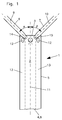
- Fig.1 Device 1 shown as a sectional drawing for carrying out precipitation reactions involving at least two starting products to at least one precipitation reaction product comprises a mixing zone 2, which is surrounded by a preferably tubular lateral surface 5 between two end regions 3 and 4 .
- Two impact jet nozzles 6 and 7 (educt jets) open out into the mixing zone at the first end region 3 for two starting products, the impact jet nozzles having oppositely oriented orientations and being inclined towards the outlet 8 in the other end region 4 .
- the axes of symmetry 9 and 10 of the impact jet nozzles 6 and 7 cross as preferred on the axis of symmetry 11 of the mixing chamber and also preferably clamp a common plane.
- the angles ⁇ and ⁇ of the two symmetry axes 9 and 10 to the symmetry axis 11 are preferably the same (Y-mixer arrangement).
- the outlet itself is formed in the example by an open end of the device in the other end region 4 .
- a multiplicity of inlets 12 for an envelope flow fluid are also preferably distributed serially and preferably at the same distance from each other on the circumference of the lateral surface.
- the sheath flow fluid or the sheath flow fluids are introduced into the device and form a sheath flow zone 13 between jacket surface and mixing zone 2 as a fluidic barrier between mixing zone and jacket surface by means of a vortex flow oriented helically to the other end 4 and adjacent to the lateral surface 5 .
- the feeds open out tangentially to the lateral surfaces in the sheath flow zone.
- the envelope flow zone does not extend beyond the outlets 14 and 15 of the impact jet nozzles 6 and 7, respectively (inner diameter of the impact jet nozzles 0.5 mm).
- the prototype is made of Plexiglas (PMMA).
- PMMA Plexiglas
- the dimensions of the sheath mixing nozzle are based on the dimensions of standard mixing nozzles without enveloping flow (eg Y and cyclone mixing nozzle).
- the envelope flow fluid was first introduced into the internal volume of the bypass flow mixing nozzle via the inlets 12 . Only then were two starting products A and B (reagents) sprayed via the respective two educt jets via the two impact jet nozzles 6 and 7 into the mixing zone. The educt jets collide, there is a rapid mixing of the educt streams without contact with the lateral surface . 5
- a preferred, because easy-to-handle envelope fluid is water.
- the entry impulse of the material streams of the starting products is used for their mixing, the mixing volume not being in contact with the inner wall of the jacket surface due to the shielding effect of the enveloping stream zone.
- the phases of the Hüllstromfluids and the reaction product and the remaining starting materials A and B mix. Dilution effects and thus influences on the product quality were not observed in fast precipitation reactions that are completed after several hundred milliseconds.
- a surface-active substance which preferably takes place via an addition via the enveloping fluid. While in the upper part near the first end 3 of the Mixing zone 2 , regardless of the Hüllstromfluid form particles, takes place with increasing flow path in the mixing zone to the second end portion 4 towards an interference of the Hüllstromfluids with the additive to the reaction product.
- the flow velocity in particular of the sheath flow fluid in the sheath flow zone, the time interval of an additive addition can be set.
- a low-viscosity silicone oil (about 5 mPas) was tested as Hüllstromfluid for use in the claimed device (sheath flow mixer). Due to the tangential to the lateral surface flow direction in the sheath flow zone and the hydrophobic properties of the oil is formed at corresponding volume flow ratios a flat continuous and thus impermeable to the aqueous phase film on the wall of the mixing zone.
- the sheath flow zone which exists continuously during operation, prevents contact between the mixture in the mixing zone (reaction medium, ie reaction products, preferably precipitation reaction products including the starting products, intermediates and mixture products) and the inner wall of the surface of the device, and thus there a possible Addition of solids to the aforementioned reaction medium.
- a subsequent phase separation of the two liquid phases takes place in the example after ei-nem discharging the mixture even after intensive mixing after only a few seconds, preferably in a gravity separator, so that silicone oil as a circulating Envelope flow fluid can be run in a separate process cycle and is recycled to the at least one inlet.
- the process scheme of the claimed method is based on Fig.2 and 3 for a discontinuous or continuous operation explained in more detail. They were used for the experimental investigation of fluid dynamics, incrustation and mixing. In this case, different combinations of aqueous educt (starting materials) and envelope flow fluids were used. In addition to water, water-insoluble fluids such as silicone oil and toluene (no results shown for the latter) were used as the sheath flow fluid as the sheath flow fluid. When water-insoluble fluids are used to build the sheath flow zone, a two-liquid phase mixture is created at the mixing outlet. This can be separated and recycled in a liquid-liquid separator (here separating funnel).
- a liquid-liquid separator here separating funnel
- Fig.2 shows a schematic drawing of the discontinuous Envelopischommischdüsenvons, such as takes place in the laboratory operation.
- the device comprises two Edukt essenceer 16 and 17 for the two output products A (first output product) and B (second output product), each via a feed pump 18 and 19 and a respective supply line 32 and 33 via the first and second impingement jet. 6 or 7 can be introduced into the mixing zone of the device 1 shown only schematically.
- the supply of the Hüllstromfluids in the device 1 takes place in the example of a reservoir 24 for the Hüllstromfluid via a syringe pump assembly 25, two valve circuits 31 and two sheath flow lines 26 in the not explicitly shown enveloping zone of the device 1. Furthermore, a separating funnel 27 of the device 1 is connected downstream. In this a device leaving the flow 28, consisting of the mixed or reaction product and the Hüllstromfluid is introduced and in the previously described in the two phases - Hüllstromfluid and mixed or reaction product - separated. The sheath flow fluid as well as the mixing or reaction product are collected in a separate catch tank 30 for further recovery.
- FIG. 3 there is a continuous, preferably a stationary operation of the enveloped stream mixing nozzle process, as it can be implemented, for example, as an industrial process.
- a continuous supply of the starting materials A and B also via corresponding feed pumps 18 and 19, leads 32 and 33 and impact jet nozzles 6 and 7 in the mixing zone of the device 1 shown only schematically , but not from containers, but from a continuous to Available educt source, preferably from a preceding production process.
- the provision of the sheath flow fluid takes place via a reservoir 24 for the sheath flow fluid, as described above.
- the supply of the sheath flow zone with sheath flow fluid also takes place via at least one sheath flow line 26 into the sheath flow zone not explicitly shown, but divergently driven by at least one sheath flow fluid pump 34.
- a previously described recycle of sheath flow fluid is proposed, preferably via means for phase separation 34 of the device leaving the volume flow 28, ie, the Hüllstromfluid and the mixing or reaction product, wherein the Hüllstromfluid is returned to the reservoir 24 .
- the sheath flow fluid thus circulates continuously in a separate circuit.
- the area of the exits of the impingement jet nozzles in the first end region of the mixing zone i. near also the outflow into the sheath flow zone inlets of the Hüllstromfluids.
- this area is particularly critical. Fast solidification reactions can easily lead to a blocking of the relatively small jet diameters of the impact jet nozzles. According to CFD, these educt feeds can be effectively protected from solid incrustations with the aid of the sheath flows, especially when the sheath flow zone extends beyond the outlet openings of the impact jet nozzles.
- LIF is a standard spectroscopic method for investigating mixing processes that allows the flow field to experimentally investigate in the sheath flow nozzle and to visualize local phenomena. For this purpose, an additional aqueous solution with a fluorescent dye is injected into the mixing zone via the jets of the starting materials.
- a fluorescent tracer dye of the aqueous phase is excited by means of a laser beam and the fluorescent light is detected by a CCD camera.
- the grayscale image obtained in this process preferably over the entire cross section of the mixing zone (diameter about 3 mm), is thus meaningful with regard to the separation of the phases.
- the sheath flow zone (silicone oil layer dark / black) extends around the outside of the mixing zone with the aqueous phase components with fluorescence agent (light / white).
- the pressure loss curves for the passage of water are considered as a reference for encrustation-free flow. So they show the pressure loss, which basically arises in the flow through the respective device or is generated by the periphery.
- the end of the process in a conventional mixing nozzle process without envelope flow zone is predetermined by the maximum pressure loss of the pumps to be compensated.
- the claimed device did not show a significant increase in the pressure loss in the course of the operating time at the volume flow rate investigated and thus also no tendency to block ( Figure 4 ).
- the curves of the pressure loss during the precipitation and the flow only with water lie on each other.
- a volume flow ratio of the envelope flow fluid (water) to the starting products of 1: 1 effectively protects the inner walls of the shell surface against solid deposits. Due to the better barrier effect of oil and other non-dissolvable with the starting products Hüllstromfluiden here is in principle a lower ratio, for example between 1: 2 and 1: 5 sufficient.
- the solid formed likewise preferably settles as encrustations on the inner wall of the lateral surfaces when no envelope flow is applied.
- the encrustations were removable by applying an elevated pressure (8 and 20 bar, preferably between 10 and 15 bar, eg 12 bar).
- the first to be used in the case of use with water as the sheath flow fluid flowed through (upper) part of the device are kept free of encrustation.
- the sheath current pulse and thus also the barrier effect decrease, and an ordinary pipe flow is formed. An accumulation of solid on the wall of the mixing zone can no longer be prevented.
- the cross-sectional widening in the axial direction is increased only by a factor of 1.0 (no widening) so that no cavitation is formed due to accelerating fluid constituents.
- the likelihood of cavitation increases with increasing expansion and decreasing mixing zone length as it decreases again with the degree of solubility of the Hüllstromfluids with the starting products and / or their mixture or precipitation reaction products.
- the upper limit for a widening of the mixing zone to twice the diameter, in particular at a complete solubility, while the widening is to be limited by the smaller factor of 1.2 if the Hüllstromfluid not or only partially with at least one of the two starting materials and / or their mixture or precipitation reaction products are soluble.
- Figure 5 shows the mixing effect with the precipitation of barium sulfate on the basis of the particle size X (in [nm]) with increasing energy dissipation rate ⁇ (in [W / kg]).
- the volume flows of the starting products are increased more and more.
- the particle size of the barium sulfate particles is measured, which is used as a measure for the assessment of the mixing at the respective volume flow. From volumetric flow and pressure loss, the energy dissipation rate can be calculated.
- the energy dissipation rate makes it possible to independently compare different types of mixers.
- the concentrations of the starting aqueous solutions of sodium sulfate and barium chloride used were 0.09 mol / l and 0.3 mol / l, respectively. As in Figure 5 shown, two areas are formed.
Landscapes
- Chemical & Material Sciences (AREA)
- Organic Chemistry (AREA)
- Chemical Kinetics & Catalysis (AREA)
- Physical Or Chemical Processes And Apparatus (AREA)
- Organic Low-Molecular-Weight Compounds And Preparation Thereof (AREA)
Applications Claiming Priority (1)
| Application Number | Priority Date | Filing Date | Title |
|---|---|---|---|
| DE102016108872.2A DE102016108872A1 (de) | 2016-05-13 | 2016-05-13 | Vorrichtung und Verfahren für die Durchführung von Fällungsreaktionen unter Beteiligung von mindestens zwei Ausgangsprodukten |
Publications (2)
| Publication Number | Publication Date |
|---|---|
| EP3243564A1 true EP3243564A1 (fr) | 2017-11-15 |
| EP3243564B1 EP3243564B1 (fr) | 2020-12-16 |
Family
ID=56694078
Family Applications (1)
| Application Number | Title | Priority Date | Filing Date |
|---|---|---|---|
| EP16401041.5A Active EP3243564B1 (fr) | 2016-05-13 | 2016-07-12 | Dispositif et procédé pour la réalisation de réactions de précipitation par association d'au moins deux produits de départ |
Country Status (2)
| Country | Link |
|---|---|
| EP (1) | EP3243564B1 (fr) |
| DE (1) | DE102016108872A1 (fr) |
Cited By (2)
| Publication number | Priority date | Publication date | Assignee | Title |
|---|---|---|---|---|
| DE102017110292A1 (de) * | 2017-05-11 | 2018-11-15 | Instillo Gmbh | Verfahren und Vorrichtung zum Herstellen von Reaktionsprodukten |
| WO2019201533A1 (fr) * | 2018-04-20 | 2019-10-24 | Robert Bosch Gmbh | Procédé et dispositif pour accélérer une réaction chimique entre au moins deux réactifs dans un réacteur chimique |
Citations (4)
| Publication number | Priority date | Publication date | Assignee | Title |
|---|---|---|---|---|
| DE102005048201A1 (de) * | 2004-10-11 | 2006-04-20 | Penth, Bernd, Dr. | Kontinuierliche Fällung von nanoskaligen Produkten in Mikroreaktoren |
| WO2009027232A1 (fr) * | 2007-08-30 | 2009-03-05 | Basf Se | Procédé de production d'isocyanates |
| WO2011116763A1 (fr) * | 2010-03-22 | 2011-09-29 | Mjr Pharmjet Gmbh | Procédé et dispositif pour la fabrication de micro- ou de nanoparticules |
| WO2014154209A1 (fr) * | 2013-03-28 | 2014-10-02 | Instillo Gmbh | Dispositif et procédé servant à produire des dispersions et des substances solides |
Family Cites Families (4)
| Publication number | Priority date | Publication date | Assignee | Title |
|---|---|---|---|---|
| DE4017709C2 (de) * | 1990-06-01 | 1994-08-04 | Tibor Dr Zoeld | Verfahren und Vorrichtung zum gesteuerten Aussondern von fluiden Substanzen aus einer Fluidströmung |
| DE4019929A1 (de) * | 1990-06-22 | 1992-01-09 | Tibor Dr Zoeld | Verfahren und vorrichtung zum einschliessen einer kernstroemung in einer huellstroemung |
| DE502005005027D1 (de) * | 2004-02-17 | 2008-09-25 | Ehrfeld Mikrotechnik Bts Gmbh | Mikromischer |
| WO2008031780A2 (fr) * | 2006-09-13 | 2008-03-20 | Basf Se | Procédé pour produire des dispersions à fines particules |
-
2016
- 2016-05-13 DE DE102016108872.2A patent/DE102016108872A1/de not_active Ceased
- 2016-07-12 EP EP16401041.5A patent/EP3243564B1/fr active Active
Patent Citations (4)
| Publication number | Priority date | Publication date | Assignee | Title |
|---|---|---|---|---|
| DE102005048201A1 (de) * | 2004-10-11 | 2006-04-20 | Penth, Bernd, Dr. | Kontinuierliche Fällung von nanoskaligen Produkten in Mikroreaktoren |
| WO2009027232A1 (fr) * | 2007-08-30 | 2009-03-05 | Basf Se | Procédé de production d'isocyanates |
| WO2011116763A1 (fr) * | 2010-03-22 | 2011-09-29 | Mjr Pharmjet Gmbh | Procédé et dispositif pour la fabrication de micro- ou de nanoparticules |
| WO2014154209A1 (fr) * | 2013-03-28 | 2014-10-02 | Instillo Gmbh | Dispositif et procédé servant à produire des dispersions et des substances solides |
Non-Patent Citations (1)
| Title |
|---|
| Y. LIU; C. CHENG; R.K. PRUD'HOMME; R.O. FOX: "Mixing in a multi-inlet vortex mixer (MIVM) for flash nano-precipitation", CHEM. ENG. SC., vol. 63, no. 11, 2008, XP022652635, DOI: doi:10.1016/j.ces.2007.10.020 |
Cited By (3)
| Publication number | Priority date | Publication date | Assignee | Title |
|---|---|---|---|---|
| DE102017110292A1 (de) * | 2017-05-11 | 2018-11-15 | Instillo Gmbh | Verfahren und Vorrichtung zum Herstellen von Reaktionsprodukten |
| DE102017110292B4 (de) * | 2017-05-11 | 2020-06-10 | Instillo Gmbh | Verfahren zum Herstellen von Reaktionsprodukten |
| WO2019201533A1 (fr) * | 2018-04-20 | 2019-10-24 | Robert Bosch Gmbh | Procédé et dispositif pour accélérer une réaction chimique entre au moins deux réactifs dans un réacteur chimique |
Also Published As
| Publication number | Publication date |
|---|---|
| EP3243564B1 (fr) | 2020-12-16 |
| DE102016108872A1 (de) | 2017-11-30 |
Similar Documents
| Publication | Publication Date | Title |
|---|---|---|
| EP2091643B1 (fr) | Procédé de production d'une minisuspoémulsion ou d'une suspension de particules coeur-écorce submicroniques | |
| DE2429291C2 (de) | Verfahren und Vorrichtung zur chemischen und/oder physikalischen Behandlung von Fluiden | |
| DE69506707T2 (de) | Verfahren und vorrichtung zur herstellung von teilchen | |
| EP0035243B1 (fr) | Procédé et dispositif de flottation | |
| DE69716224T2 (de) | Vorrichtungen zur Herstellung von Feinpartikeln | |
| DE69922173T2 (de) | Verfahren zur herstellung von teilchen | |
| EP3641931B1 (fr) | Réacteur fluide | |
| EP3283209B1 (fr) | Dispositif, utilisation et procédé de pulvérisation de liquides et de production d'un brouillard de fines | |
| DE3886910T2 (de) | Emulgierungsverfahren und -vorrichtung. | |
| DE10206083B4 (de) | Verfahren zum Erzeugen monodisperser Nanotropfen sowie mikrofluidischer Reaktor zum Durchführen des Verfahrens | |
| DE2151206C2 (de) | Vorrichtung zum Herstellen einer Emulsion | |
| EP2566607B1 (fr) | Procédé et dispositif destinés à ajouter et à mélanger un produit chimique dans un flux de traitement | |
| DE69719721T2 (de) | Hochgeschwindigkeits - Kollisions - Reaktionsverfahren | |
| DE60022195T2 (de) | Verfahren und vorrichtung zur herstellung von teilchen | |
| EP3243564B1 (fr) | Dispositif et procédé pour la réalisation de réactions de précipitation par association d'au moins deux produits de départ | |
| EP1049531A1 (fr) | Dispositif permettant de melanger puis de pulveriser des liquides | |
| EP2572778B1 (fr) | Machine de flottaison avec une buse de dispersion et procédé de fonctionnementen | |
| DE925400C (de) | Verfahren und Vorrichtung zum fortlaufenden zentrifugalen Dekantieren von Aufschlaemmungen fester Teilchen in einer Fluessigkeit | |
| DE10148615B4 (de) | Verfahren und Vorrichtung zur Durchführung chemischer Prozesse | |
| EP2163300B1 (fr) | Utilisation d'une plaque de distribution d'écoulements fluidiques | |
| DE2460232A1 (de) | Verfahren zur erzeugung einer kernstroemung in wasser-in-oel-emulsion oder dispersion | |
| DE2746782C3 (de) | Verfahren zur Gewinnung von Harzpulver und Zweistoffdüse zur Durchführung des Verfahrens | |
| WO2007042133A1 (fr) | Reacteur a couche de separation avec ecoulement elongationnel | |
| WO1995006519A1 (fr) | Procede de fabrication de granules en lit fluidise et de produits seches par pulverisation | |
| EP4323094A1 (fr) | Dispositif et procédé de dispersion de gaz dans des liquides |
Legal Events
| Date | Code | Title | Description |
|---|---|---|---|
| PUAI | Public reference made under article 153(3) epc to a published international application that has entered the european phase |
Free format text: ORIGINAL CODE: 0009012 |
|
| STAA | Information on the status of an ep patent application or granted ep patent |
Free format text: STATUS: THE APPLICATION HAS BEEN PUBLISHED |
|
| AK | Designated contracting states |
Kind code of ref document: A1 Designated state(s): AL AT BE BG CH CY CZ DE DK EE ES FI FR GB GR HR HU IE IS IT LI LT LU LV MC MK MT NL NO PL PT RO RS SE SI SK SM TR |
|
| AX | Request for extension of the european patent |
Extension state: BA ME |
|
| STAA | Information on the status of an ep patent application or granted ep patent |
Free format text: STATUS: REQUEST FOR EXAMINATION WAS MADE |
|
| 17P | Request for examination filed |
Effective date: 20180718 |
|
| RBV | Designated contracting states (corrected) |
Designated state(s): AL AT BE BG CH CY CZ DE DK EE ES FI FR GB GR HR HU IE IS IT LI LT LU LV MC MK MT NL NO PL PT RO RS SE SI SK SM TR |
|
| STAA | Information on the status of an ep patent application or granted ep patent |
Free format text: STATUS: EXAMINATION IS IN PROGRESS |
|
| 17Q | First examination report despatched |
Effective date: 20181212 |
|
| GRAP | Despatch of communication of intention to grant a patent |
Free format text: ORIGINAL CODE: EPIDOSNIGR1 |
|
| STAA | Information on the status of an ep patent application or granted ep patent |
Free format text: STATUS: GRANT OF PATENT IS INTENDED |
|
| INTG | Intention to grant announced |
Effective date: 20200630 |
|
| GRAS | Grant fee paid |
Free format text: ORIGINAL CODE: EPIDOSNIGR3 |
|
| GRAJ | Information related to disapproval of communication of intention to grant by the applicant or resumption of examination proceedings by the epo deleted |
Free format text: ORIGINAL CODE: EPIDOSDIGR1 |
|
| GRAL | Information related to payment of fee for publishing/printing deleted |
Free format text: ORIGINAL CODE: EPIDOSDIGR3 |
|
| STAA | Information on the status of an ep patent application or granted ep patent |
Free format text: STATUS: EXAMINATION IS IN PROGRESS |
|
| GRAP | Despatch of communication of intention to grant a patent |
Free format text: ORIGINAL CODE: EPIDOSNIGR1 |
|
| STAA | Information on the status of an ep patent application or granted ep patent |
Free format text: STATUS: GRANT OF PATENT IS INTENDED |
|
| GRAA | (expected) grant |
Free format text: ORIGINAL CODE: 0009210 |
|
| STAA | Information on the status of an ep patent application or granted ep patent |
Free format text: STATUS: THE PATENT HAS BEEN GRANTED |
|
| INTC | Intention to grant announced (deleted) | ||
| INTG | Intention to grant announced |
Effective date: 20201028 |
|
| AK | Designated contracting states |
Kind code of ref document: B1 Designated state(s): AL AT BE BG CH CY CZ DE DK EE ES FI FR GB GR HR HU IE IS IT LI LT LU LV MC MK MT NL NO PL PT RO RS SE SI SK SM TR |
|
| REG | Reference to a national code |
Ref country code: GB Ref legal event code: FG4D Free format text: NOT ENGLISH |
|
| REG | Reference to a national code |
Ref country code: IE Ref legal event code: FG4D Free format text: LANGUAGE OF EP DOCUMENT: GERMAN |
|
| REG | Reference to a national code |
Ref country code: DE Ref legal event code: R096 Ref document number: 502016011971 Country of ref document: DE |
|
| REG | Reference to a national code |
Ref country code: AT Ref legal event code: REF Ref document number: 1345086 Country of ref document: AT Kind code of ref document: T Effective date: 20210115 |
|
| PG25 | Lapsed in a contracting state [announced via postgrant information from national office to epo] |
Ref country code: NO Free format text: LAPSE BECAUSE OF FAILURE TO SUBMIT A TRANSLATION OF THE DESCRIPTION OR TO PAY THE FEE WITHIN THE PRESCRIBED TIME-LIMIT Effective date: 20210316 Ref country code: RS Free format text: LAPSE BECAUSE OF FAILURE TO SUBMIT A TRANSLATION OF THE DESCRIPTION OR TO PAY THE FEE WITHIN THE PRESCRIBED TIME-LIMIT Effective date: 20201216 Ref country code: FI Free format text: LAPSE BECAUSE OF FAILURE TO SUBMIT A TRANSLATION OF THE DESCRIPTION OR TO PAY THE FEE WITHIN THE PRESCRIBED TIME-LIMIT Effective date: 20201216 Ref country code: GR Free format text: LAPSE BECAUSE OF FAILURE TO SUBMIT A TRANSLATION OF THE DESCRIPTION OR TO PAY THE FEE WITHIN THE PRESCRIBED TIME-LIMIT Effective date: 20210317 |
|
| REG | Reference to a national code |
Ref country code: NL Ref legal event code: MP Effective date: 20201216 |
|
| PG25 | Lapsed in a contracting state [announced via postgrant information from national office to epo] |
Ref country code: SE Free format text: LAPSE BECAUSE OF FAILURE TO SUBMIT A TRANSLATION OF THE DESCRIPTION OR TO PAY THE FEE WITHIN THE PRESCRIBED TIME-LIMIT Effective date: 20201216 Ref country code: BG Free format text: LAPSE BECAUSE OF FAILURE TO SUBMIT A TRANSLATION OF THE DESCRIPTION OR TO PAY THE FEE WITHIN THE PRESCRIBED TIME-LIMIT Effective date: 20210316 Ref country code: LV Free format text: LAPSE BECAUSE OF FAILURE TO SUBMIT A TRANSLATION OF THE DESCRIPTION OR TO PAY THE FEE WITHIN THE PRESCRIBED TIME-LIMIT Effective date: 20201216 |
|
| PG25 | Lapsed in a contracting state [announced via postgrant information from national office to epo] |
Ref country code: HR Free format text: LAPSE BECAUSE OF FAILURE TO SUBMIT A TRANSLATION OF THE DESCRIPTION OR TO PAY THE FEE WITHIN THE PRESCRIBED TIME-LIMIT Effective date: 20201216 Ref country code: NL Free format text: LAPSE BECAUSE OF FAILURE TO SUBMIT A TRANSLATION OF THE DESCRIPTION OR TO PAY THE FEE WITHIN THE PRESCRIBED TIME-LIMIT Effective date: 20201216 |
|
| REG | Reference to a national code |
Ref country code: LT Ref legal event code: MG9D |
|
| PG25 | Lapsed in a contracting state [announced via postgrant information from national office to epo] |
Ref country code: SM Free format text: LAPSE BECAUSE OF FAILURE TO SUBMIT A TRANSLATION OF THE DESCRIPTION OR TO PAY THE FEE WITHIN THE PRESCRIBED TIME-LIMIT Effective date: 20201216 Ref country code: LT Free format text: LAPSE BECAUSE OF FAILURE TO SUBMIT A TRANSLATION OF THE DESCRIPTION OR TO PAY THE FEE WITHIN THE PRESCRIBED TIME-LIMIT Effective date: 20201216 Ref country code: EE Free format text: LAPSE BECAUSE OF FAILURE TO SUBMIT A TRANSLATION OF THE DESCRIPTION OR TO PAY THE FEE WITHIN THE PRESCRIBED TIME-LIMIT Effective date: 20201216 Ref country code: CZ Free format text: LAPSE BECAUSE OF FAILURE TO SUBMIT A TRANSLATION OF THE DESCRIPTION OR TO PAY THE FEE WITHIN THE PRESCRIBED TIME-LIMIT Effective date: 20201216 Ref country code: PT Free format text: LAPSE BECAUSE OF FAILURE TO SUBMIT A TRANSLATION OF THE DESCRIPTION OR TO PAY THE FEE WITHIN THE PRESCRIBED TIME-LIMIT Effective date: 20210416 Ref country code: RO Free format text: LAPSE BECAUSE OF FAILURE TO SUBMIT A TRANSLATION OF THE DESCRIPTION OR TO PAY THE FEE WITHIN THE PRESCRIBED TIME-LIMIT Effective date: 20201216 Ref country code: SK Free format text: LAPSE BECAUSE OF FAILURE TO SUBMIT A TRANSLATION OF THE DESCRIPTION OR TO PAY THE FEE WITHIN THE PRESCRIBED TIME-LIMIT Effective date: 20201216 |
|
| PG25 | Lapsed in a contracting state [announced via postgrant information from national office to epo] |
Ref country code: PL Free format text: LAPSE BECAUSE OF FAILURE TO SUBMIT A TRANSLATION OF THE DESCRIPTION OR TO PAY THE FEE WITHIN THE PRESCRIBED TIME-LIMIT Effective date: 20201216 |
|
| REG | Reference to a national code |
Ref country code: DE Ref legal event code: R097 Ref document number: 502016011971 Country of ref document: DE |
|
| PG25 | Lapsed in a contracting state [announced via postgrant information from national office to epo] |
Ref country code: IS Free format text: LAPSE BECAUSE OF FAILURE TO SUBMIT A TRANSLATION OF THE DESCRIPTION OR TO PAY THE FEE WITHIN THE PRESCRIBED TIME-LIMIT Effective date: 20210416 |
|
| PLBE | No opposition filed within time limit |
Free format text: ORIGINAL CODE: 0009261 |
|
| STAA | Information on the status of an ep patent application or granted ep patent |
Free format text: STATUS: NO OPPOSITION FILED WITHIN TIME LIMIT |
|
| PG25 | Lapsed in a contracting state [announced via postgrant information from national office to epo] |
Ref country code: AL Free format text: LAPSE BECAUSE OF FAILURE TO SUBMIT A TRANSLATION OF THE DESCRIPTION OR TO PAY THE FEE WITHIN THE PRESCRIBED TIME-LIMIT Effective date: 20201216 Ref country code: IT Free format text: LAPSE BECAUSE OF FAILURE TO SUBMIT A TRANSLATION OF THE DESCRIPTION OR TO PAY THE FEE WITHIN THE PRESCRIBED TIME-LIMIT Effective date: 20201216 |
|
| 26N | No opposition filed |
Effective date: 20210917 |
|
| PG25 | Lapsed in a contracting state [announced via postgrant information from national office to epo] |
Ref country code: DK Free format text: LAPSE BECAUSE OF FAILURE TO SUBMIT A TRANSLATION OF THE DESCRIPTION OR TO PAY THE FEE WITHIN THE PRESCRIBED TIME-LIMIT Effective date: 20201216 |
|
| PG25 | Lapsed in a contracting state [announced via postgrant information from national office to epo] |
Ref country code: ES Free format text: LAPSE BECAUSE OF FAILURE TO SUBMIT A TRANSLATION OF THE DESCRIPTION OR TO PAY THE FEE WITHIN THE PRESCRIBED TIME-LIMIT Effective date: 20201216 |
|
| PG25 | Lapsed in a contracting state [announced via postgrant information from national office to epo] |
Ref country code: SI Free format text: LAPSE BECAUSE OF FAILURE TO SUBMIT A TRANSLATION OF THE DESCRIPTION OR TO PAY THE FEE WITHIN THE PRESCRIBED TIME-LIMIT Effective date: 20201216 |
|
| REG | Reference to a national code |
Ref country code: CH Ref legal event code: PL |
|
| PG25 | Lapsed in a contracting state [announced via postgrant information from national office to epo] |
Ref country code: MC Free format text: LAPSE BECAUSE OF FAILURE TO SUBMIT A TRANSLATION OF THE DESCRIPTION OR TO PAY THE FEE WITHIN THE PRESCRIBED TIME-LIMIT Effective date: 20201216 |
|
| REG | Reference to a national code |
Ref country code: BE Ref legal event code: MM Effective date: 20210731 |
|
| PG25 | Lapsed in a contracting state [announced via postgrant information from national office to epo] |
Ref country code: LI Free format text: LAPSE BECAUSE OF NON-PAYMENT OF DUE FEES Effective date: 20210731 Ref country code: CH Free format text: LAPSE BECAUSE OF NON-PAYMENT OF DUE FEES Effective date: 20210731 |
|
| PG25 | Lapsed in a contracting state [announced via postgrant information from national office to epo] |
Ref country code: IS Free format text: LAPSE BECAUSE OF FAILURE TO SUBMIT A TRANSLATION OF THE DESCRIPTION OR TO PAY THE FEE WITHIN THE PRESCRIBED TIME-LIMIT Effective date: 20210416 Ref country code: LU Free format text: LAPSE BECAUSE OF NON-PAYMENT OF DUE FEES Effective date: 20210712 |
|
| PG25 | Lapsed in a contracting state [announced via postgrant information from national office to epo] |
Ref country code: IE Free format text: LAPSE BECAUSE OF NON-PAYMENT OF DUE FEES Effective date: 20210712 Ref country code: BE Free format text: LAPSE BECAUSE OF NON-PAYMENT OF DUE FEES Effective date: 20210731 |
|
| REG | Reference to a national code |
Ref country code: AT Ref legal event code: MM01 Ref document number: 1345086 Country of ref document: AT Kind code of ref document: T Effective date: 20210712 |
|
| PG25 | Lapsed in a contracting state [announced via postgrant information from national office to epo] |
Ref country code: AT Free format text: LAPSE BECAUSE OF NON-PAYMENT OF DUE FEES Effective date: 20210712 |
|
| PGFP | Annual fee paid to national office [announced via postgrant information from national office to epo] |
Ref country code: GB Payment date: 20220725 Year of fee payment: 7 Ref country code: DE Payment date: 20220621 Year of fee payment: 7 |
|
| PGFP | Annual fee paid to national office [announced via postgrant information from national office to epo] |
Ref country code: FR Payment date: 20220725 Year of fee payment: 7 |
|
| PG25 | Lapsed in a contracting state [announced via postgrant information from national office to epo] |
Ref country code: HU Free format text: LAPSE BECAUSE OF FAILURE TO SUBMIT A TRANSLATION OF THE DESCRIPTION OR TO PAY THE FEE WITHIN THE PRESCRIBED TIME-LIMIT; INVALID AB INITIO Effective date: 20160712 |
|
| PG25 | Lapsed in a contracting state [announced via postgrant information from national office to epo] |
Ref country code: CY Free format text: LAPSE BECAUSE OF FAILURE TO SUBMIT A TRANSLATION OF THE DESCRIPTION OR TO PAY THE FEE WITHIN THE PRESCRIBED TIME-LIMIT Effective date: 20201216 |
|
| REG | Reference to a national code |
Ref country code: DE Ref legal event code: R119 Ref document number: 502016011971 Country of ref document: DE |
|
| GBPC | Gb: european patent ceased through non-payment of renewal fee |
Effective date: 20230712 |
|
| PG25 | Lapsed in a contracting state [announced via postgrant information from national office to epo] |
Ref country code: MK Free format text: LAPSE BECAUSE OF FAILURE TO SUBMIT A TRANSLATION OF THE DESCRIPTION OR TO PAY THE FEE WITHIN THE PRESCRIBED TIME-LIMIT Effective date: 20201216 Ref country code: DE Free format text: LAPSE BECAUSE OF NON-PAYMENT OF DUE FEES Effective date: 20240201 Ref country code: GB Free format text: LAPSE BECAUSE OF NON-PAYMENT OF DUE FEES Effective date: 20230712 |
|
| PG25 | Lapsed in a contracting state [announced via postgrant information from national office to epo] |
Ref country code: FR Free format text: LAPSE BECAUSE OF NON-PAYMENT OF DUE FEES Effective date: 20230731 |