EP3243560A1 - Desulphurization of marine exhaust flue gas - Google Patents
Desulphurization of marine exhaust flue gas Download PDFInfo
- Publication number
- EP3243560A1 EP3243560A1 EP16169118.3A EP16169118A EP3243560A1 EP 3243560 A1 EP3243560 A1 EP 3243560A1 EP 16169118 A EP16169118 A EP 16169118A EP 3243560 A1 EP3243560 A1 EP 3243560A1
- Authority
- EP
- European Patent Office
- Prior art keywords
- slurry
- scrubber
- flue gas
- exhaust flue
- magnesium hydroxide
- Prior art date
- Legal status (The legal status is an assumption and is not a legal conclusion. Google has not performed a legal analysis and makes no representation as to the accuracy of the status listed.)
- Withdrawn
Links
Images

Classifications
-
- B—PERFORMING OPERATIONS; TRANSPORTING
- B01—PHYSICAL OR CHEMICAL PROCESSES OR APPARATUS IN GENERAL
- B01D—SEPARATION
- B01D53/00—Separation of gases or vapours; Recovering vapours of volatile solvents from gases; Chemical or biological purification of waste gases, e.g. engine exhaust gases, smoke, fumes, flue gases, aerosols
- B01D53/14—Separation of gases or vapours; Recovering vapours of volatile solvents from gases; Chemical or biological purification of waste gases, e.g. engine exhaust gases, smoke, fumes, flue gases, aerosols by absorption
- B01D53/1412—Controlling the absorption process
-
- B—PERFORMING OPERATIONS; TRANSPORTING
- B01—PHYSICAL OR CHEMICAL PROCESSES OR APPARATUS IN GENERAL
- B01D—SEPARATION
- B01D53/00—Separation of gases or vapours; Recovering vapours of volatile solvents from gases; Chemical or biological purification of waste gases, e.g. engine exhaust gases, smoke, fumes, flue gases, aerosols
- B01D53/14—Separation of gases or vapours; Recovering vapours of volatile solvents from gases; Chemical or biological purification of waste gases, e.g. engine exhaust gases, smoke, fumes, flue gases, aerosols by absorption
- B01D53/1425—Regeneration of liquid absorbents
-
- B—PERFORMING OPERATIONS; TRANSPORTING
- B01—PHYSICAL OR CHEMICAL PROCESSES OR APPARATUS IN GENERAL
- B01D—SEPARATION
- B01D53/00—Separation of gases or vapours; Recovering vapours of volatile solvents from gases; Chemical or biological purification of waste gases, e.g. engine exhaust gases, smoke, fumes, flue gases, aerosols
- B01D53/14—Separation of gases or vapours; Recovering vapours of volatile solvents from gases; Chemical or biological purification of waste gases, e.g. engine exhaust gases, smoke, fumes, flue gases, aerosols by absorption
- B01D53/1456—Removing acid components
- B01D53/1481—Removing sulfur dioxide or sulfur trioxide
-
- B—PERFORMING OPERATIONS; TRANSPORTING
- B01—PHYSICAL OR CHEMICAL PROCESSES OR APPARATUS IN GENERAL
- B01D—SEPARATION
- B01D53/00—Separation of gases or vapours; Recovering vapours of volatile solvents from gases; Chemical or biological purification of waste gases, e.g. engine exhaust gases, smoke, fumes, flue gases, aerosols
- B01D53/14—Separation of gases or vapours; Recovering vapours of volatile solvents from gases; Chemical or biological purification of waste gases, e.g. engine exhaust gases, smoke, fumes, flue gases, aerosols by absorption
- B01D53/18—Absorbing units; Liquid distributors therefor
-
- B—PERFORMING OPERATIONS; TRANSPORTING
- B01—PHYSICAL OR CHEMICAL PROCESSES OR APPARATUS IN GENERAL
- B01D—SEPARATION
- B01D53/00—Separation of gases or vapours; Recovering vapours of volatile solvents from gases; Chemical or biological purification of waste gases, e.g. engine exhaust gases, smoke, fumes, flue gases, aerosols
- B01D53/34—Chemical or biological purification of waste gases
- B01D53/74—General processes for purification of waste gases; Apparatus or devices specially adapted therefor
- B01D53/77—Liquid phase processes
- B01D53/78—Liquid phase processes with gas-liquid contact
-
- B—PERFORMING OPERATIONS; TRANSPORTING
- B01—PHYSICAL OR CHEMICAL PROCESSES OR APPARATUS IN GENERAL
- B01D—SEPARATION
- B01D2251/00—Reactants
- B01D2251/40—Alkaline earth metal or magnesium compounds
- B01D2251/402—Alkaline earth metal or magnesium compounds of magnesium
-
- B—PERFORMING OPERATIONS; TRANSPORTING
- B01—PHYSICAL OR CHEMICAL PROCESSES OR APPARATUS IN GENERAL
- B01D—SEPARATION
- B01D2252/00—Absorbents, i.e. solvents and liquid materials for gas absorption
- B01D2252/10—Inorganic absorbents
- B01D2252/103—Water
- B01D2252/1035—Sea water
-
- B—PERFORMING OPERATIONS; TRANSPORTING
- B01—PHYSICAL OR CHEMICAL PROCESSES OR APPARATUS IN GENERAL
- B01D—SEPARATION
- B01D2257/00—Components to be removed
- B01D2257/30—Sulfur compounds
- B01D2257/302—Sulfur oxides
-
- B—PERFORMING OPERATIONS; TRANSPORTING
- B01—PHYSICAL OR CHEMICAL PROCESSES OR APPARATUS IN GENERAL
- B01D—SEPARATION
- B01D2258/00—Sources of waste gases
- B01D2258/01—Engine exhaust gases
-
- B—PERFORMING OPERATIONS; TRANSPORTING
- B01—PHYSICAL OR CHEMICAL PROCESSES OR APPARATUS IN GENERAL
- B01D—SEPARATION
- B01D2258/00—Sources of waste gases
- B01D2258/01—Engine exhaust gases
- B01D2258/012—Diesel engines and lean burn gasoline engines
-
- B—PERFORMING OPERATIONS; TRANSPORTING
- B01—PHYSICAL OR CHEMICAL PROCESSES OR APPARATUS IN GENERAL
- B01D—SEPARATION
- B01D2259/00—Type of treatment
- B01D2259/45—Gas separation or purification devices adapted for specific applications
- B01D2259/4566—Gas separation or purification devices adapted for specific applications for use in transportation means
Definitions
- the present application relates to the field of reducing the amount of SO x in exhaust flue gases from marine vessels using wet scrubbers. More specifically, the application relates to increasing the SOx absorption capacity of scrubber liquid used in a closed loop mode of the scrubber by using a magnesium hydroxide slurry for cleaning the used scrubber liquid.
- Fossil fuel combustion is used in industrial processes for many different purposes.
- fossil fuel combustion produces several contaminants, which have been found to be detrimental to the environment.
- sulphur and nitrogen oxide compounds are the major components of "acid rain”.
- Sulphur is a naturally occurring element in crude oil, concentrated in the residual components of the crude oil distillation process.
- the amount of sulphur in the fuel oil depends mainly on the source of crude oil, and to a lesser extent on the refining process.
- SO x is a result of the combustion of sulphur containing compounds that are especially abundant in low-grade fuels. Typically for fuel on a worldwide basis, the value is in the order of 1.5-4 %.
- These values lead to high concentration of SO 2 in flue gases. For example, when using a fuel containing 1.5% S, the concentration of SO 2 in the emitted gas is about 630 ppm, and with a fuel containing 4% S, the concentration of SO 2 in the emitted gas is about 1700ppm.
- SECAs Sulphur Emission Control Areas
- Marine vessels typically use lean burn combustion engines and lower grade fuels that both results in high levels of SO x and particles present in the exhaust flue gas.
- FGD flue gas desulphurization
- the scrubbing solution may be water, seawater or any other aqueous solution of one or more compounds known to bind, or absorb, one or more of the constituencies of the flue gas to be scrubbed.
- Acidic gases as SO x are normally removed from a solution by scrubbing with an alkaline solution, such as an aqueous solution of an alkaline compound, such as caustic soda or other alkaline substances.
- a wet scrubber may be a packed scrubber, in which the scrubber or at least part of the scrubber is filled with a packing.
- the scrubbing solution flows at the surface of the packing to ascertain a large contact surface between the scrubber liquid and the gas that flows through the packing.
- the wet scrubber may not have a packing, but the scrubber liquid is sprayed into the scrubber to form a rain or a fog of scrubber liquid that is brought into contact with the flue gas to be scrubbed.
- the scrubber may also constitute both packed and non-packed zones.
- the particles in the flue gas are taken along with the scrubber liquid and may either be released out of the wet scrubber together with the scrubber liquid, or are removed from the scrubber liquid by means of filters, centrifugation or any other means to separate solid particles from a liquid.
- seawater As a scrubber liquid, fresh seawater is relatively efficient. However, in certain geographical areas, for instance in the Baltic Sea, the discharge of seawater that has been used as a scrubber liquid for exhaust flue gases of marine vessels has been prohibited. To fulfil these requirements, there is a need for a closed loop scrubbing solution, i.e. a solution in which the scrubbing water is recirculated. Seawater however has a limited buffer capacity. Due to the acidic nature of the SO x present in the exhaust flue gas, the scrubber seawater becomes acidic and loses its SO x absorption capacity when used in a closed loop system.
- caustic soda sodium hydroxide or NaOH
- NaOH sodium hydroxide
- magnesium oxide MgO
- magnesium hydroxide Mg(OH) 2
- alkali materials such as sodium hydroxide
- magnesium oxide and magnesium hydroxide may generally be considered as non-hazardous materials.
- magnesium oxide and magnesium hydroxide may be safer for the personnel that may handle, or otherwise into contact with these materials, and may be safer for the environment, e.g.; in the event of a spill or a leak that may make its way into the surface water around and/or outside the marine vessel.
- the absorption of SO x in an aqueous solution of Mg(OH) 2 may be exemplified by the absorption of SO 2 according to the following equations: Absorption reaction 1: Mg(OH) 2 + SO 2 ⁇ MgSO 3 + H 2 O Absorption reaction 2: MgSO 3 + SO 2 + H 2 O ⁇ Mg(HSO 3 ) 2 Total reaction: Mg(OH) 2 + 2SO 2 ⁇ Mg(HSO 3 ) 2
- Mg(OH) 2 is normally provided to the user in the form of a suspension or a slurry of Mg(OH) 2 in water.
- Mg(OH) 2 has a low solubility in water, and additives are normally used to avoid settling of Mg(OH) 2 to avoid the need for constant agitation of the suspension.
- the vibrations on-board of a vessel seem to reduce the effect of the chemical normally used to maintain Mg(OH) 2 in suspension.
- MgO may be provided as a powder to be dissolved and reacted with water to according to the following equation: MgO + H 2 O ⁇ Mg(OH) 2
- the reaction above is highly exothermal and due care has to be taken to avoid excessive heating resulting boiling and potentially hazardous situations.
- US 2015/0283499 discloses the use of a high solids magnesium hydroxide slurry in connection with exhaust scrubber systems for removing SOx and NOx compounds from exhaust gas emissions.
- the slurry includes a magnesium hydroxide compound and a carbohydrate-based viscosity control agent.
- the slurry may further include seawater as at least a portion of the liquid component.
- the magnesium compound utilized for forming the slurries include a magnesium oxide or a magnesium hydroxide material, which are amongst others provided in a powdered form. The powdered magnesium compound is then mixed with the available seawater traversed by the marine vessel to produce a magnesium hydroxide slurry having a relatively high solids concentration.
- magnesium compounds in the form of magnesium oxide powders require less storage space in a bunker of a marine vessel than alkali sources such as sodium hydroxide. Furthermore, the use of magnesium oxide and/or magnesium hydroxide may result in less sludge that may need to be managed by the owner of the marine vessel and eventually removed from the marine vessel and disposed of.
- Magnesium oxide and/or magnesium hydroxide are also generally known as being non-corrosive to metal surfaces, including the metal components of the marine vessel, as well as the metal components of the storage and pumping equipment and the exhaust scrubber system.
- a marine exhaust flue gas desulphurization system for reducing the amount of sulphur oxides present in an exhaust flue gas of one or more diesel engines of a marine vessel, the marine exhaust flue gas desulphurization system comprising:
- the flue exhaust gas passes through a screen of scrubber liquid, more particularly water and most particularly seawater.
- SO x is removed from the exhaust gas and consumes all the alkalinity contained in the scrubbing water.
- the SO x in the water changes to SO 3 , which further changes to H 2 SO 4 in the presence of oxygen according to the following equations: pH adjustment: Mg(HSO 3 ) 2 + Mg(OH) 2 ⁇ MgSO 3 + H 2 O oxidation: MgSO 3 + 1 ⁇ 2 O 2 ⁇ MgSO 4
- this used scrubber liquid cannot be discharged into the sea in which the marine vessel sails and has to be recycled.
- the acidified scrubber liquid can however not be re-used anymore into the wet scrubber since the acidity will reduce the adsorption capacity of SO x in the exhaust flue gas.
- the magnesium hydroxide slurry that is formed through the hydrolysis of magnesium oxide and/or magnesium hydroxide slurry with water, will neutralize the acidic scrubber liquid formed during the wet scrubbing process of the exhaust flue gas.
- the magnesium hydroxide slurry further thus takes care that the SO x absorption capacity of the scrubber liquid is again increased.
- the preparation reservoir further comprises
- the controlled addition of powder in the preparation reservoir avoids overheating due to the exothermal reaction between the magnesium oxide powder and the water that are both added to the preparation reservoir.
- the marine exhaust gas desulphurization system comprises a storage reservoir that is placed in series with the preparation reservoir and that is connected to the preparation reservoir via a slurry withdrawal pipe, the preparation reservoir and the storage reservoir optionally comprising pressure transmitter means that are arranged to indicate the actual level of the magnesium hydroxide slurry present in the preparation reservoir and the storage reservoir.
- a second reservoir in the form of a storage reservoir for holding the magnesium hydroxide slurry takes care of a better hydrolisation meaning that a more homogeneous magnesium hydroxide slurry is obtained and the process of cleaning the used scrubber liquid can be controlled in a better way.
- the slurry transporting means comprise slurry transporting pipes for withdrawing the magnesium hydroxide slurry from the preparation reservoir and/or the storage reservoir
- the wet scrubber system comprises one or more used scrubber liquid withdrawal pipes for withdrawing the used scrubber liquid from the wet scrubber
- the slurry transporting pipes are connected to the one or more used scrubber liquid withdrawal pipes
- the slurry transporting pipes optionally comprising slurry pumping means arranged in the slurry withdrawal pipe for pumping the slurry out of the preparation reservoir into the storage reservoir and slurry pumping means in the slurry transporting pipes for pumping the slurry out of the storage reservoir towards the scrubber liquid withdrawal pipes.
- marine exhaust flue gas desulphurization system comprises flushing means arranged for flushing the slurry pumping means and all pipes through which slurry flows after the slurry pumping means stopped pumping slurry.
- the powder transportation and addition means comprise one or more multi-screw conveyors that are arranged to be started and stopped at any time during the process of adding the magnesium oxide and/or magnesium hydroxide to the preparation reservoir.
- Multi-screw conveyors are reliable and the feeding speed may be controlled by starting and stopping the multi-screw conveyors.
- the marine exhaust flue gas desulphurization system comprises dust arrestor means that comprise a dust arrester pipe that is in connection with the preparation reservoir and that comprise water spraying means arranged to spray water into the dust arrester pipe.
- the wet scrubber is a scrubber of the spraying type without a packing
- the wet scrubber comprises a scrubbing tower having a multiplicity of spraying nozzles that each are arranged for spraying the scrubber liquid into the scrubbing tower in order to be brought into contact with the exhaust flue gas
- the scrubbing tower optionally comprising two serially connected scrubbing chambers, each scrubbing chamber having at least one nozzle and one scrubber liquid withdrawal pipe for withdrawing the used scrubber liquid out of the respective scrubbing chamber
- the marine exhaust flue gas desulphurization system comprises a main scrubber liquid pipe arranged to transport scrubber liquid to the spraying nozzles provided in the scrubber tower, the main scrubber liquid pipe comprising a cooler arranged to cool the scrubber liquid that is conveyed towards the spraying nozzles.
- the marine exhaust flue gas desulphurization system comprises a filter unit to filter the used scrubber liquid.
- a method for reducing the amount of sulphur oxides present in an exhaust flue gas of a diesel engine of a marine vessel comprising the steps of
- the prepared magnesium hydroxide slurry is pumped out of the preparation reservoir into a storage reservoir via a slurry withdrawal pipe using pumping means.
- used scrubber liquid is withdrawn from the wet scrubber via one of more used scrubber liquid withdrawal pipes, and wherein magnesium hydroxide slurry from the storage reservoir is brought into contact with the used scrubber liquid via slurry transporting pipes forming part of the slurry transporting means.
- the method is performed using a marine exhaust flue gas desulphurization system according to the application as described above.
- the exhaust flue gas (100) produced by one or more diesel engines (not shown in figure 1 ) of the marine vessel is introduced into the bottom part of a wet scrubber (1) via a flue gas exhaust pipe (2).
- the wet scrubber (1) specifically is a wet scrubber without a packing.
- the wet scrubber (1) comprises a scrubbing tower having a multiplicity of spraying nozzles (3, 3') that each are arranged for spraying the scrubber liquid into the scrubbing tower in order to be brought into contact with the exhaust flue gas.
- the spray nozzles (3, 3') are arranged for a maximum contact between droplets of the scrubber liquid exiting from the spray nozzles (3, 3') and the exhaust flue gas passing through the wet scrubber tower.
- the scrubber liquid is introduced into the spray nozzles (3) via scrubber liquid sub pipes (4', 4").
- the scrubber liquid sub pipes (4', 4") are connected to a scrubber liquid main pipe (4).
- the scrubbed exhaust flue gas is released into the surroundings via a scrubbed exhaust gas outlet pipe (5).
- Used scrubber liquid is collected in the wet scrubber (1) and is withdrawn through used scrubber liquid withdrawal pipe(s) (6, 6').
- the wet scrubber (1) as shown in figure 1 is more particularly a two-step wet scrubber having two serially connected scrubbing chambers (not shown on figure 1 ), wherein each of the scrubbing chambers has one spray nozzle (3, 3') and one scrubber liquid withdrawal pipe (6, 6').
- the scrubber liquid in the scrubber liquid withdrawal pipes (6, 6') is collected and further led through an open loop mode outlet pipe (7) that is controlled by a valve (8), or through a closed loop mode scrubber liquid recycle pipe (9) that is controlled by a valve (10).
- the valve (10) In the open loop mode of the wet scrubbing system, the valve (10) is closed and the valve (8) is open, such that the used scrubber liquid is withdrawn through the outlet pipe (7) and is released into the surrounding sea via a water outlet (11).
- seawater In the open loop mode, seawater is taken in from the surrounding sea via a seawater inlet (12), a seawater pipe (14), via a valve (22), a scrubber liquid pump (13) and introduced into the scrubber liquid pipes (4, 4', 4").
- the valve (22) In the open loop mode, the valve (22) is open.
- valve (10) is open, such that the used scrubber liquid is led through the closed loop mode scrubber liquid recycle pipe (9) and is introduced into a used scrubber liquid tank (20), which in the closed loop mode serves as a scrubber liquid reservoir.
- the recycle valve (23) which is arranged on the scrubber liquid recycle pipe (24) for recycling of scrubber liquid from the used scrubber liquid tank (20), is opened.
- the scrubber liquid in the tank (20) is recycled via the recycle pipe (24), the valve (23) and the pump (13) into the scrubber liquid pipes (4, 4', 4").
- the valve (22) is in the closed loop mode controlled to balance any loss of scrubber liquid in the recycled scrubber liquid.
- the recycling scrubber liquid is heated by the hot exhaust gas in the wet scrubber (1).
- a cooler (27) may be arranged in scrubber liquid pipe (4) to cool the scrubber liquid.
- the cooler (27) receives cooling water from the seawater inlet (12) via a cooling water pipe (25) and a cooling water pump (26). Cooling water is withdrawn from the cooler (27) in a cooling water return pipe (28), and is released to the surrounding via the seawater outlet (11).
- the skilled person will understand that the mentioned seawater outlet (11) may be one or more outlet(s), each for releasing one or more water streams into the surrounding sea.
- a Mg(OH) 2 -slurry is added to the used scrubber liquid.
- MgO-powder is agitated with water in a preparation reservoir (32).
- the Mg(OH) 2 -slurry is formed by the hydrolysis of the MgO-powder with water.
- MgO-powder can be brought on-board of the marine vessel either in big-bags (30) or in silo's (39).
- Big bags (30) are commonly used for delivery of dry matter in different technical areas, and may have a capacity up to 1000 kg, or more.
- the big bags (30) used in the present application more in particular have a capacity of more than 500 kg.
- the big bags (30) have a big bag spout (not shown on figure 2 ) in the bottom thereof.
- a big-bag connection clamp (not shown on figure 2 ) can be provided to eliminate dust emissions, loss of powder or contamination of the powder.
- a hoisting device (80) is provided using more in particular a yoke (83) for lifting the big bag (30) and bringing it in the correct position to rest onto a support cone (81') arranged as a support for the big bag (30) and for assisting in emptying the big bag (30).
- This support cone (81') forms part of a big bag discharger (81).
- a vibrator (82) can be arranged to vibrate the big bag (30) if MgO-powder would get stuck in the big bag (30), and to get all or most MgO-powder out of the big bag (30).
- a big bag connector (87) is provided to connect the big bag spout to it.
- the big bag discharger (81) can be supplied with a pneumatic air cleaned dust filter (84) with a fan (85).
- the dust filter (84) is installed to avoid that powder dust would enter the surrounding area when a big bag (30) is replaced.
- the fan (85) is used when an empty big-bag (30) is removed and evacuates the air in the empty big bag (30).
- a pneumatic cylinder (86) can be provided to raise and lower the big bag connector (87) such that the big bag spout can easily be connected to it.
- the MgO-powder is pumped out of a bulk truck (101) to the silo (39) using the compressor on the bulk truck (101) via a filling pipe (107) that is connected to the silo (39).
- This filling pipe (107) is provided with a hose valve (98) that is more in particular pneumatically operated. This hose valve (98) can be opened or closed.
- the filling pipe (107) can furthermore be arranged with a ring ejector (97) that avoids clogging of powder in the filling pipe (107). Once the higher pressure builds up in the filling pipe (107), the ring ejector (97) will automatically start and boost the powder filling capacity of the silo (39).
- the ring ejector (97) adds pressurized air to the transported powder.
- the ring ejector (97) thus helps the transportation through a long vertical filling pipe (107) and helps to ensure the transport throughout the filling pipe (107).
- a pressure transmitter (91) is mounted inside the silo (39).
- a high pressure alarm can be produced by the pressure transmitter (91) to indicate that the pressure limit of 40 bar inside the silo (39) is reached.
- a high pressure will close the hose valve (98) and the filling of the silo (39) will be stopped at that moment.
- the one or more pressure relief valves (99) on top of the silo (39) are arranged to open at 50mbar and are provided to protect the silo (39) in case the pressure increase inside the silo (39) is too high.
- the hose valve (98) closes at a high pressure inside the silo (39) or when the silo (39) is full.
- a dust filter (92) can be installed at the top of the silo (39 to prevent dust being released into the surrounding while filling the silo (39).
- the air which is used for transporting the MgO-powder from the bulk truck (101) to the silo (39) is released via this dust filter (92).
- a control box (93) with manoeuvre buttons and indicator lamps (94) can be used.
- a number of level indicators indicating a certain level of the powder in the silo (39) can be provided.
- a full level silo indicator (102) can be provided.
- a low level silo indicator (103) can be provided.
- an arch or empty level of the silo (39) can be provided.
- the full level silo indicator (102) activates an alarm produced by a horn (96) as well by a flash light (95) and activates a stop filling sequence meaning that the operator needs to stop filling the silo (39).
- the low level silo indicator (103) activates a low level alarm when the MgO-powder in the silo (39) is lower than a specified level indicated in the parameter list of the silo (39).
- the arch or empty level indicator (104) is located at the back of the upper multi-screw conveyor (31) and it indicates that the silo (39) is empty. When the arch or empty level indicator (104) is activated, an arch breaking system starts an arch breaking sequence, meaning that the arch build-up in the bottom cone (39') of the silo (39).
- the arch breaking system comprises a number of nozzles (105), more in particular plate nozzles (105), that are provided in the bottom cone (39') of the silo (39).
- Each of the plate nozzles (105) is controlled by a respective non-return valve (106).
- the non-return valves (106) are opened and compressed air in the form of a pulse will be sent to the bottom cone (39') of the silo (39) through the plate nozzles (105) to break the arch.
- powder transportation and addition means (31, 31') (see figures 2 and 3 ) are provided.
- the powder transportation and addition means more particularly comprise a multi-screw feeder (31) that is located above a multi-screw conveyor (31').
- the multi-screw feeder (31) has a large active discharge area and helps to discharge the magnesium oxide powder in a reliable way to the multi-screw conveyor. Both are arranged to be started and stopped at any time during the process of adding the magnesium oxide powder to the preparation reservoir (32).
- the multi-screw feeder (31) runs at a constant speed which will be set during the commissioning phase.
- the multi-screw feeder (31) has a capacity of approximately 500 kg/hr.
- a rotation indicator (88) can be arranged to monitor the rotation speed of the multi-screw feeder (31).
- An alarm level can be set in the operation program for indicating a low rotation speed of the multi-screw feeder (31) for a period of more than one second and for the multi-screw conveyor (31') in case there is a low rotation speed for a period of more than 60 ms.
- the multi-screw conveyor (31') can be arranged to run when a butterfly valve (89), that is provided on a (flexible) connection (90) that forms a connection between the outer end of the multi-screw conveyor (31') and the preparation reservoir (32), is in an open position.
- This butterfly valve (89) is provided to prevent moisture from the preparation reservoir (32) to reach up into the multi-screw conveyor (31').
- the butterfly valve (89) is more in particular arranged to operate automatically.
- controlling means are provided to control that the powder transportation and addition means (31, 31') gradually add magnesium oxide powder to the preparation reservoir (32), this in order to avoid overheating due to the exothermal reaction between the magnesium oxide powder and water.
- the preparation reservoir (32) may be provided with an insulation.
- water addition means in order to add water, more particularly fresh water, to the preparation reservoir (32), water addition means, in particular a fresh water pipe (42), are provided.
- a flow meter (37) may be provided. The magnesium oxide powder and the water are more in particular added simultaneously to the preparation reservoir (32).
- magnesium hydroxide slurry meaning MgO wt% and water wt% of the slurry, a range of between 20 and maximum 30 weight% of MgO-powder and between 80 and minimum 70 weight% of water are added together in the preparation reservoir (32).
- agitation means (44) in order to agitate the MgO-powder with the water, agitation means (44), more particularly in the form of a stirrer, are provided. These agitation means (44) are particularly provided inside the preparation reservoir (32). These agitation means (44) more particularly agitate continuously as long as the level of the magnesium hydroxide slurry is above a predetermined minimum level.
- pressure transmitter means (57) (see figure 2 ) are provided.
- An overfilling level switch (59) controls the maximum level in the preparation reservoir (32) by giving a signal to the controlling means to stop the addition of powder by the multi-screw conveyors (31, 31') and the addition of the water in the preparation reservoir (32).
- dust arrestor means (43) can be arranged to reduce the formation of magnesium oxide powder dust caused by the introduction of the powder into the preparation reservoir (32).
- the dust arrestor means (43) comprises one or more spray nozzles for forming a fresh water spray to humidify the magnesium oxide powder dust formed, and thus to capture the magnesium oxide and/or magnesium hydroxide dust and allow the humidified magnesium oxide and/or magnesium hydroxide dust to fall into the preparation reservoir (32).
- the fresh water for the dust arrestor means (43) is conveniently a side stream taken from the fresh water pipe (42).
- the preparation reservoir (32) is provided with a temperature transmitter (57) to measure the temperature inside the preparation reservoir (32).
- the magnesium hydroxide slurry that is prepared in the preparation reservoir (32) is then withdrawn from the preparation reservoir (32) into a storage reservoir (34) via slurry transporting means that comprise a slurry withdrawal pipe (40) and two slurry withdrawal sub pipes (40', 40").
- the slurry withdrawal sub pipes (40', 40") are placed in parallel.
- the slurry withdrawal pipe parts (40, 40') are provided with different valves (50) that are arranged to control the flow of the magnesium hydroxide slurry therein.
- the slurry withdrawal pipe parts (40, 40') come back together to one slurry withdrawal pipe (40) after the pumps (33, 33').
- the storage reservoir (34) is placed in series with the preparation reservoir (32).
- Pumping means (33, 33') are used to pump the Mg(OH) 2 -slurry out of the preparation reservoir (32) into the storage reservoir (34). This is particularly an automatic process.
- the pumping means more in particular comprise two pumps (33, 33') that are placed in parallel.
- One of the two pumps (33, 33') is on duty, while the other one (33', 33) will be standby.
- the other of the two pumps (33, 33') can be switched on.
- manual valves (not shown on figure 2 ) will have to be set in the correct position to enable the change of the operation modus of the pumps (33, 33').
- a respective filter (45, 45') is provided in order to remove particles of the magnesium hydroxide slurry that are large enough to damage the pumps (33, 33').
- the slurry withdrawal pipe (40) is furthermore connected to a flush water pipe (46) that is provided to flow water through it for flushing the pumps (33, 33'), the filters (45, 45'), the valves (50) and the slurry withdrawal pipe (40) and slurry withdrawal sub pipes (40', 40").
- the storage reservoir (34) is provided with agitation means (47), particularly in the form of a stirrer, to agitate the magnesium hydroxide slurry that is contained therein in order to keep the magnesium hydroxide slurry properly mixed with the water and avoid sedimentation of the slurry to the bottom of the storage reservoir (34).
- the agitation means (47) agitate as long as the level of the magnesium hydroxide slurry is above a predetermined level.
- Pressure transmitter means (52) are arranged to determine the actual level of the magnesium hydroxide slurry in the storage reservoir (34).
- temperature transmitter means (53) are arranged to monitor the temperature inside the storage reservoir (34).
- valve (76) In case of a too high temperature due to a too high concentration of magnesium hydroxide, the valve (76) is opened and fresh water will be added to decrease the temperature in the storage reservoir (34) to a pre-set temperature limit.
- These pre-set temperature limit can be 70°C, 75°C or 80°C, more particularly 75°C.
- the storage reservoir (34) is connected to the closed loop mode scrubber liquid recycle pipe (9) via slurry transporting means (36, 36', 55) and pumping means (35, 35').
- the slurry transporting means more particularly comprise slurry transporting pipes comprising more in particular two slurry transporting sub pipes (36, 36') that are placed in parallel, and optionally a slurry transporting main pipe (55) that is placed in series with each of the slurry transporting sub pipes (36, 36').
- the slurry transporting pipes (36, 36') come together to one slurry transporting main pipe (55) that is arranged with a pressure transmitter (56). This slurry transporting main pipe (55) is in its turn connected to the closed loop mode scrubber liquid recycle pipe (9).
- each of the two slurry transporting sub pipes (36, 36') are connected to the closed loop mode scrubber liquid recycle pipe (9).
- the pumping means more particularly comprise two dosing pumps (35, 35') that are placed in parallel and that each are placed on a respective slurry transporting sub pipe (36, 36').
- the dosing pumps (35, 35') are in particular frequency controlled dosing pumps to dose the magnesium hydroxide slurry to the closed loop mode scrubber liquid recycle pipe (9).
- Each of the slurry transporting sub pipes (36, 36') is furthermore connected to a flush water pipe (48, 48') that is provided to flow water through it for flushing the slurry transporting sub pipes (36, 36') and the dosing pumps (35, 35'), as well as the main slurry transporting pipe (55) as shown in figure 2 .
- a flushing valve (54, 54') is provided on these flush water pipes (48, 48').
- Each of the slurry transporting sub pipes (36, 36') are furthermore provided with a valve (60, 60') that is opened as soon as the wet scrubber system switches to the closed loop mode or starts in a closed loop mode.
- the dosing pumps (35, 35') are arranged to stop if the wet scrubber system stop working. As soon as the dosing pumps (35, 35') stop feeding the magnesium hydroxide slurry to the closed mode scrubber liquid recycle pipe (9), the dosing pumps (35, 35'), the slurry transporting sub pipes (36, 36') and the slurry transporting main pipe (55) need to be flushed to avoid sedimentation and clogging in these elements. This is done by opening each of the flushing valves (54, 54').
- one or more pressure transmitters (56, 56') can be provided to stop the dosing pumps (35, 35') in case of a too high pressure.
- one pressure transmitter (56) is provided in the slurry transporting main pipe (55), while in figure 3 , in each of the slurry transporting sub pipes (36, 36'), such a pressure transmitter (56, 56') is provided.
- the magnesium hydroxide slurry is added to the used scrubber liquid in the closed loop mode scrubber liquid recycle pipe (9) according to the need to maintain the scrubbing efficiency and the SO x removal capacity of the (used) scrubber liquid.
- the pH of the used scrubber liquid is preferably adjusted to a pH between 5 and 6.
- the scrubber liquid that is recycled during the closed loop mode of the scrubber system will contain increasing concentrations of solid matter, mainly soot and residues of unburned fuel, mainly polyaromatic hydrocarbons (PAH).
- PAH polyaromatic hydrocarbons
- the increasing amount of particulate material sets a maximum period for operation in closed loop mode.
- a part of the used scrubber liquid present in the used scrubber liquid tank (20) is withdrawn in a scrubber liquid withdrawal pipe (69) and a scrubber liquid withdrawal pump (61) to a filter unit (62).
- filter unit (62) There are different known filter techniques available for this purpose.
- a particular filter unit comprises a pre-filter for removing coarse particulate matter, such as a dead end filter particle (for instance having a size of > 1000 ⁇ m, or > 800 ⁇ m), and a filter for removal of the finer particles (for instance with a pore size of the ceramic filter of 0.04 ⁇ m).
- the scrubbing water is filtered in the pre-filter to remove particles of a size that may cause problems in downstream filters.
- the filter for removing the pre-filtered scrubber liquid may be a ceramic SiC membrane filter unit, composed of 2 stages (or recirculation loops) that can be operated more or less independent of each other. Each loop contains several, such as 4, ceramic SiC membranes mounted in parallel with a total membrane filtration area of several square meters.
- the pre-filtered scrubber liquid is pumped into the membrane stages with a common feed pump, which has the additional function of pressurizing the stages and establishing a transmembrane pressure across the membrane.
- Recirculation pumps furthermore circulate the water inside the recirculation loops and thereby create high turbulence on the membrane surface to prevent particle deposition.
- the membrane system is capable of carrying out fully automated back flushes, back pulses and chemical cleaning cycles (CIP) in regular intervals according to sequences that have been programed in the PLC of the system. These techniques are used to remove any flocculants that will accumulate on the membrane surface with increasing filtration time.
- CIP chemical cleaning cycles
- the filtering and cleaning of the used scrubber liquid, and the dewatering of the filter cake allows safe and clean on-board handling and storage of the filter cake.
- the used scrubber liquid is divided into two streams by the filter unit (62).
- the two streams leave the filter unit (62) continuously.
- the stream that passes through the filter unit (62) is purified and is withdrawn via a purified water withdrawal pipe (63).
- the liquid withdrawn in the purified water withdrawal pipe (63) represents typically about 90-95% of the scrubbing liquid fed into the filter unit (62).
- the retentate from the filter unit (62) containing the majority of the particles and PAH, and the concentration of solids in the retentate stream is concentrated by a factor of 10 to 20, to about 0.5 to 1.0 % by weight of solids.
- the retentate is withdrawn from the filter unit in a retentate pipe (63), and introduced into a dewatering unit (65).
- the pH of the retentate is adjusted to a pH between 6 and 8, if needed, by addition of alkali or acid, and a surface active polymer.
- the surface active polymers cross links particles in the suspension with each other, creating a flocculated suspension including large particle agglomerates that can be more easily dewatered.
- the retentate is then introduced into a dewatering press.
- a dewatering press a screw or filter press can be used, into which the flocculated suspension is transported from the mixing chamber into the dewatering section of the press by a transporting screw.
- the screw press is expected to produce a sludge amount of about 10-20 kg/h with a dry solids content in the range of 10-30 wt% as well as a reject water steam (about 500 l/h) that can either be discharged overboard or recycled back to the used scrubber liquid tank (20).
- the purified water in pipe (63), or parts thereof, may be recycled back to the used scrubber liquid tank (20) via a purified water return pipe (67), and/or withdrawn from the recycling of the scrubber liquid.
- the purified water withdrawn from the recycling of scrubber liquid may be introduced into a granular activated carbon filter (70) to remove or substantially reduce the amount of PAH in the filtered water before introducing the water into a waste water pipe (71).
- the purified water may be introduced directly into the waste water pipe (71) via a bypass pipe (69).
- the flow of the water in pipe (63) into pipe (67), pipe (69) or the carbon filter (70) is controlled by a valve (68) depending of the need for recycled water into used scrubber liquid tank (20), and/or environmental requirements.
- the purified water in pipe (63) may be released into the surrounding sea as it is, or temporary deposited into a waste water tank (74).
- the waste water tank (74) may be emptied in harbor, or into the sea in waters where it is allowed to dump waste water.
- a pump (75) is arranged to pump waste water from the waste water tank (74) into a waste water release pipe (73) connected to the water outlet (11).
- a possible wet scrubber to be used in connection with the present application is a wet scrubber as described in WO 2014/128261 , but the present application is not bound to any specific wet scrubber design.
Abstract
The application relates to a marine exhaust flue gas desulphurization system for reducing the amount of sulphur oxides present in an exhaust flue gas of one or more diesel engines of a marine vessel. The marine exhaust flue gas desulphurization system comprises a wet scrubber system comprising at least one wet scrubber (1) using a scrubber liquid for scrubbing the exhaust flue gases originating from the diesel engine of the marine vessel, resulting in a used scrubber liquid, the wet scrubber system (1) arranged to run in a closed loop mode, at least one preparation reservoir (32) arranged for preparing a magnesium hydroxide slurry by hydrolysing water with a magnesium oxide powder, powder transportation and addition means (31, 31') for adding magnesium oxide powder to the preparation reservoir, water addition means (42) for adding water to the preparation reservoir (32) and agitation means (44) arranged for agitating the magnesium oxide powder with the water that are both added to the preparation reservoir (32) forming the magnesium hydroxide slurry, and slurry transporting means (40, 40', 40", 36, 36', 55) for transporting the prepared magnesium hydroxide slurry towards the used scrubber liquid when the wet scrubber system is running in the closed loop mode. The application furthermore relates to a method for reducing the amount of sulphur oxides present in an exhaust flue gas of one or more diesel engines of a marine vessel.
Description
- The present application relates to the field of reducing the amount of SOx in exhaust flue gases from marine vessels using wet scrubbers. More specifically, the application relates to increasing the SOx absorption capacity of scrubber liquid used in a closed loop mode of the scrubber by using a magnesium hydroxide slurry for cleaning the used scrubber liquid.
- Fossil fuel combustion is used in industrial processes for many different purposes. Unfortunately, fossil fuel combustion produces several contaminants, which have been found to be detrimental to the environment. In particular, sulphur and nitrogen oxide compounds are the major components of "acid rain". Sulphur is a naturally occurring element in crude oil, concentrated in the residual components of the crude oil distillation process. The amount of sulphur in the fuel oil depends mainly on the source of crude oil, and to a lesser extent on the refining process. SOx is a result of the combustion of sulphur containing compounds that are especially abundant in low-grade fuels. Typically for fuel on a worldwide basis, the value is in the order of 1.5-4 %. These values lead to high concentration of SO2 in flue gases. For example, when using a fuel containing 1.5% S, the concentration of SO2 in the emitted gas is about 630 ppm, and with a fuel containing 4% S, the concentration of SO2 in the emitted gas is about 1700ppm.
- Ships are fast becoming the biggest source of air pollution in the EU. Unless more action is taken, they are set to emit more than all land sources combined by 2020.
- European waters have introduced as one of the first in the world more stringent sulphur emission regulations for ships, with the being into force of the so-called Sulphur Emission Control Areas (SECAs) in the Baltic Sea in 2006, followed by the North Sea and English Channel in 2007.
- Under the European Union (EU) Marine Sulphur Directive, only low-sulphur fuels of less than 1.5% S are permitted. Furthermore a 1.5% sulphur cap in fuel are applied to fuels used by passenger vessels operating regular services to and from any community port from August 11, 2006, and not just in SECAs. The EU legislation allows using technologies that abate the sulphur content in the emitted gas as an alternative to using low-sulphur fuels (of 1.5% S). Thus, the technology should assure reductions in sulphur emissions that are at least equal to, or better, than those achieved by lowering the sulphur content in bunker fuel.
- Marine vessels typically use lean burn combustion engines and lower grade fuels that both results in high levels of SOx and particles present in the exhaust flue gas.
- One possibility to reduce the content of SOx in the exhaust flue gas of marine vessels is by using low sulphur content fuels. Low sulphur content fuels are however far more expensive than normal low grade fuels.
- Since the high costs of the low sulphur content fuels, the ship builders and owners have been forced to look for other solutions to reduce the SOx-content in the exhaust flue gas of the normal low grade fuels, this not only for new ships to be built but also more importantly for the current fleet of marine vessels.
- Most of the flue gas desulphurization (FGD) technologies use wet scrubbing processes in which the emitted flue gases are brought into intimate contact with an aqueous scrubbing solution. The aim of these processes is to provide high absorption efficiencies and to remove, or substantially reduce, the concentration of particles, droplets or substances in the flue gas to be scrubbed. The scrubbing solution may be water, seawater or any other aqueous solution of one or more compounds known to bind, or absorb, one or more of the constituencies of the flue gas to be scrubbed. Acidic gases as SOx are normally removed from a solution by scrubbing with an alkaline solution, such as an aqueous solution of an alkaline compound, such as caustic soda or other alkaline substances.
- A wet scrubber may be a packed scrubber, in which the scrubber or at least part of the scrubber is filled with a packing. The scrubbing solution flows at the surface of the packing to ascertain a large contact surface between the scrubber liquid and the gas that flows through the packing. Alternatively, the wet scrubber may not have a packing, but the scrubber liquid is sprayed into the scrubber to form a rain or a fog of scrubber liquid that is brought into contact with the flue gas to be scrubbed. The scrubber may also constitute both packed and non-packed zones.
- The particles in the flue gas are taken along with the scrubber liquid and may either be released out of the wet scrubber together with the scrubber liquid, or are removed from the scrubber liquid by means of filters, centrifugation or any other means to separate solid particles from a liquid.
- As a scrubber liquid, fresh seawater is relatively efficient. However, in certain geographical areas, for instance in the Baltic Sea, the discharge of seawater that has been used as a scrubber liquid for exhaust flue gases of marine vessels has been prohibited. To fulfil these requirements, there is a need for a closed loop scrubbing solution, i.e. a solution in which the scrubbing water is recirculated. Seawater however has a limited buffer capacity. Due to the acidic nature of the SOx present in the exhaust flue gas, the scrubber seawater becomes acidic and loses its SOx absorption capacity when used in a closed loop system.
- In order to solve this problem, caustic soda (sodium hydroxide or NaOH) is the most commonly used chemical to control the pH in sulphur dioxide wet scrubbers. However, caustic soda is potentially hazardous for a worker to handle. Furthermore, caustic soda may, if overdosed, cause a pH that is far too high for depositing of the scrubber seawater into the sea.
- Instead of caustic soda, it is also known to add magnesium oxide (MgO) or magnesium hydroxide (Mg(OH)2) to the scrubbing (sea)water to increase its scrubbing capacity and / or to maintain the alkalinity and consequently the scrubbing capacity of the scrubber (sea)water in a closed scrubber liquid loop. By contrast to alkali materials such as sodium hydroxide, magnesium oxide and magnesium hydroxide may generally be considered as non-hazardous materials. As such, magnesium oxide and magnesium hydroxide may be safer for the personnel that may handle, or otherwise into contact with these materials, and may be safer for the environment, e.g.; in the event of a spill or a leak that may make its way into the surface water around and/or outside the marine vessel.
- The absorption of SOx in an aqueous solution of Mg(OH)2 may be exemplified by the absorption of SO2 according to the following equations:
Absorption reaction 1: Mg(OH)2 + SO2 → MgSO3 + H2O Absorption reaction 2: MgSO3 + SO2 + H2O → Mg(HSO3)2 Total reaction: Mg(OH)2 + 2SO2 → Mg(HSO3)2 - Mg(OH)2 is normally provided to the user in the form of a suspension or a slurry of Mg(OH)2 in water. Mg(OH)2 has a low solubility in water, and additives are normally used to avoid settling of Mg(OH)2 to avoid the need for constant agitation of the suspension. However, the vibrations on-board of a vessel seem to reduce the effect of the chemical normally used to maintain Mg(OH)2 in suspension.
- Alternatively, MgO may be provided as a powder to be dissolved and reacted with water to according to the following equation:
MgO + H2O → Mg(OH)2
The reaction above is highly exothermal and due care has to be taken to avoid excessive heating resulting boiling and potentially hazardous situations. -
US 2015/0283499 discloses the use of a high solids magnesium hydroxide slurry in connection with exhaust scrubber systems for removing SOx and NOx compounds from exhaust gas emissions. The slurry includes a magnesium hydroxide compound and a carbohydrate-based viscosity control agent. The slurry may further include seawater as at least a portion of the liquid component. The magnesium compound utilized for forming the slurries include a magnesium oxide or a magnesium hydroxide material, which are amongst others provided in a powdered form. The powdered magnesium compound is then mixed with the available seawater traversed by the marine vessel to produce a magnesium hydroxide slurry having a relatively high solids concentration. - It is known that the magnesium compounds in the form of magnesium oxide powders require less storage space in a bunker of a marine vessel than alkali sources such as sodium hydroxide. Furthermore, the use of magnesium oxide and/or magnesium hydroxide may result in less sludge that may need to be managed by the owner of the marine vessel and eventually removed from the marine vessel and disposed of. Magnesium oxide and/or magnesium hydroxide are also generally known as being non-corrosive to metal surfaces, including the metal components of the marine vessel, as well as the metal components of the storage and pumping equipment and the exhaust scrubber system.
- It is a goal of the application to provide a marine exhaust flue gas desulphurization system wherein the SOx absorption capacity of the scrubber liquid is increased by using a magnesium hydroxide slurry formed by the hydrolisation of water and magnesium oxide powder, avoiding the addition of chemical components to the magnesium hydroxide slurry.
- According to a first aspect of the present application, a marine exhaust flue gas desulphurization system for reducing the amount of sulphur oxides present in an exhaust flue gas of one or more diesel engines of a marine vessel, the marine exhaust flue gas desulphurization system comprising:
- a wet scrubber system comprising at least one wet scrubber arranged for scrubbing the exhaust flue gases originating from the diesel engine of the marine vessel using a scrubber liquid, thereby generating a used scrubber liquid, the wet scrubber system being arranged to run in a closed loop mode;
- at least one preparation reservoir arranged for preparing a magnesium hydroxide slurry by hydrolysing water with a magnesium oxide powder under agitation conditions;
- slurry transporting means for transporting the prepared magnesium hydroxide slurry towards the wet scrubber system, there contacting the magnesium hydroxide slurry with the used scrubber liquid and cleaning the used scrubber liquid, when the wet scrubber system is running in the closed loop mode.
- During the wet scrubbing process, the flue exhaust gas passes through a screen of scrubber liquid, more particularly water and most particularly seawater. During this process, SOx is removed from the exhaust gas and consumes all the alkalinity contained in the scrubbing water. Through the absorption of SOx and other harmful gases by the water, the pH of the water is reduced. The SOx in the water changes to SO3, which further changes to H2SO4 in the presence of oxygen according to the following equations:
pH adjustment: Mg(HSO3)2 + Mg(OH)2 → MgSO3 + H2O
oxidation: MgSO3 + ½ O2 → MgSO4
- In some areas, this used scrubber liquid cannot be discharged into the sea in which the marine vessel sails and has to be recycled. The acidified scrubber liquid can however not be re-used anymore into the wet scrubber since the acidity will reduce the adsorption capacity of SOx in the exhaust flue gas. In order to solve this problem, the magnesium hydroxide slurry that is formed through the hydrolysis of magnesium oxide and/or magnesium hydroxide slurry with water, will neutralize the acidic scrubber liquid formed during the wet scrubbing process of the exhaust flue gas. The magnesium hydroxide slurry further thus takes care that the SOx absorption capacity of the scrubber liquid is again increased.
- By preparing the magnesium hydroxide slurry in a preparation reservoir using agitating means, there is a fast mixing between the magnesium oxide powder with the water.
- In an embodiment of a marine exhaust flue gas desulphurization system according to the application, the preparation reservoir further comprises
- (a) agitation means arranged to continuously agitate the magnesium hydroxide slurry prepared in the preparation reservoir as long as the level of the magnesium hydroxide slurry is above a predetermined minimum level;
- (b) water addition means arranged to add water, in particular fresh water, into the preparation reservoir in case the temperature of the prepared magnesium hydroxide slurry increases above a pre-set temperature limit, optionally comprising a flow meter arranged to measure the flow of the water that is added to the preparation reservoir; and/or
- (c) controlling means arranged to control the addition of magnesium oxide powder to the preparation reservoir thereby gradually adding magnesium oxide powder to the preparation reservoir
- By continuously agitating the magnesium hydroxide slurry, sedimentation of the magnesium hydroxide of the prepared slurry to the bottom of the preparation reservoir will be avoided.
- The controlled addition of powder in the preparation reservoir avoids overheating due to the exothermal reaction between the magnesium oxide powder and the water that are both added to the preparation reservoir.
- In a possible embodiment of a marine exhaust flue gas desulphurization system according to the application, the marine exhaust gas desulphurization system comprises a storage reservoir that is placed in series with the preparation reservoir and that is connected to the preparation reservoir via a slurry withdrawal pipe, the preparation reservoir and the storage reservoir optionally comprising pressure transmitter means that are arranged to indicate the actual level of the magnesium hydroxide slurry present in the preparation reservoir and the storage reservoir.
- The provision of a second reservoir in the form of a storage reservoir for holding the magnesium hydroxide slurry takes care of a better hydrolisation meaning that a more homogeneous magnesium hydroxide slurry is obtained and the process of cleaning the used scrubber liquid can be controlled in a better way.
- In a particular embodiment of a marine exhaust flue gas desulphurization system according to the application, the slurry transporting means comprise slurry transporting pipes for withdrawing the magnesium hydroxide slurry from the preparation reservoir and/or the storage reservoir, and the wet scrubber system comprises one or more used scrubber liquid withdrawal pipes for withdrawing the used scrubber liquid from the wet scrubber, wherein the slurry transporting pipes are connected to the one or more used scrubber liquid withdrawal pipes, the slurry transporting pipes optionally comprising slurry pumping means arranged in the slurry withdrawal pipe for pumping the slurry out of the preparation reservoir into the storage reservoir and slurry pumping means in the slurry transporting pipes for pumping the slurry out of the storage reservoir towards the scrubber liquid withdrawal pipes.
- In an embodiment of a marine exhaust flue gas desulphurization system according to the application, marine exhaust flue gas desulphurization system comprises flushing means arranged for flushing the slurry pumping means and all pipes through which slurry flows after the slurry pumping means stopped pumping slurry.
- In a possible embodiment of a marine exhaust flue gas desulphurization system according to the application, the powder transportation and addition means comprise one or more multi-screw conveyors that are arranged to be started and stopped at any time during the process of adding the magnesium oxide and/or magnesium hydroxide to the preparation reservoir.
- Multi-screw conveyors are reliable and the feeding speed may be controlled by starting and stopping the multi-screw conveyors.
- In an embodiment of a marine exhaust flue gas desulphurization system according to the application, the marine exhaust flue gas desulphurization system comprises dust arrestor means that comprise a dust arrester pipe that is in connection with the preparation reservoir and that comprise water spraying means arranged to spray water into the dust arrester pipe.
- These dust arrestor means avoids that dust from the magnesium oxide powder to come out.
- In an embodiment of a marine exhaust flue gas desulphurization system according to the application, the wet scrubber is a scrubber of the spraying type without a packing, and wherein the wet scrubber comprises a scrubbing tower having a multiplicity of spraying nozzles that each are arranged for spraying the scrubber liquid into the scrubbing tower in order to be brought into contact with the exhaust flue gas, the scrubbing tower optionally comprising two serially connected scrubbing chambers, each scrubbing chamber having at least one nozzle and one scrubber liquid withdrawal pipe for withdrawing the used scrubber liquid out of the respective scrubbing chamber
- Particularly, the marine exhaust flue gas desulphurization system comprises a main scrubber liquid pipe arranged to transport scrubber liquid to the spraying nozzles provided in the scrubber tower, the main scrubber liquid pipe comprising a cooler arranged to cool the scrubber liquid that is conveyed towards the spraying nozzles.
- In an embodiment of a marine exhaust flue gas desulphurization system according to the application, the marine exhaust flue gas desulphurization system comprises a filter unit to filter the used scrubber liquid.
- According to a second aspect of the application, a method for reducing the amount of sulphur oxides present in an exhaust flue gas of a diesel engine of a marine vessel is disclosed, the method comprising the steps of
- conveying exhaust flue gases created in the diesel engine of the marine vessel to a wet scrubber system that is running in a closed loop mode;
- scrubbing the exhaust flue gases in the wet scrubber system using a scrubber liquid thereby forming a used scrubber liquid;
- preparing a magnesium hydroxide slurry by adding magnesium oxide powder and water to a preparation reservoir (32) under agitating conditions;
- transporting the prepared magnesium hydroxide slurry to the wet scrubber system via slurry transporting means (40, 40', 40", 36, 36', 55); and;
- contacting the magnesium hydroxide slurry with the used scrubber liquid slurry transporting means thereby cleaning the used scrubber liquid when the wet scrubber system is running in the closed loop mode of the scrubber liquid.
- (a) continuously agitating the magnesium hydroxide slurry in the preparation reservoir using agitation means as long as the level of the magnesium hydroxide slurry is above a predetermined level;
- (b) gradually adding the magnesium oxide powder to the preparation reservoir by the powder transportation and addition means under the control of controlling means; and/or
- (c) adding water to the preparation reservoir using water addition means in case the temperature of the prepared magnesium hydroxide slurry in the preparation reservoir increases above a pre-set temperature limit.
- In a possible method according to the application, the prepared magnesium hydroxide slurry is pumped out of the preparation reservoir into a storage reservoir via a slurry withdrawal pipe using pumping means.
- Particularly, used scrubber liquid is withdrawn from the wet scrubber via one of more used scrubber liquid withdrawal pipes, and wherein magnesium hydroxide slurry from the storage reservoir is brought into contact with the used scrubber liquid via slurry transporting pipes forming part of the slurry transporting means.
- In a possible method according to the application, the method is performed using a marine exhaust flue gas desulphurization system according to the application as described above.
-
-
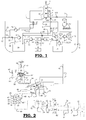
Fig. 1 illustrates a schematic overview of a marine exhaust flue gas desulphurization system including a wet scrubber system for treating exhaust flue gas of one or more diesel engines of a marine vessel and treatment of the recycled used scrubber liquid by means of Mg(OH)2-slurry; -
Fig. 2 illustrates a powder feeding and mixing system for MgO-powder delivered in big bags; -
Fig. 3 illustrates a powder feeding and mixing system for bulk delivery of MgO-powder and storage on-board in a silo. - The skilled person reading the description below will understand that when an element such as a pipe, a pump, a valve, an intake, an outlet, a tank, a reservoir, a nozzle etc. is mentioned in singular form, the mentioned element may be in plural form, i.e. two or more elements may be present if not explicitly excluded. Accordingly, when a pipe is mentioned, the expression may also include two or more pipes arranged in parallel or in series. This is also applicable to all the mentioned elements.
- As can be seen in
figure 1 , the exhaust flue gas (100) produced by one or more diesel engines (not shown infigure 1 ) of the marine vessel is introduced into the bottom part of a wet scrubber (1) via a flue gas exhaust pipe (2). The wet scrubber (1) specifically is a wet scrubber without a packing. The wet scrubber (1) comprises a scrubbing tower having a multiplicity of spraying nozzles (3, 3') that each are arranged for spraying the scrubber liquid into the scrubbing tower in order to be brought into contact with the exhaust flue gas. The spray nozzles (3, 3') are arranged for a maximum contact between droplets of the scrubber liquid exiting from the spray nozzles (3, 3') and the exhaust flue gas passing through the wet scrubber tower. The scrubber liquid is introduced into the spray nozzles (3) via scrubber liquid sub pipes (4', 4"). The scrubber liquid sub pipes (4', 4") are connected to a scrubber liquid main pipe (4). The scrubbed exhaust flue gas is released into the surroundings via a scrubbed exhaust gas outlet pipe (5). - Used scrubber liquid is collected in the wet scrubber (1) and is withdrawn through used scrubber liquid withdrawal pipe(s) (6, 6'). The wet scrubber (1) as shown in
figure 1 is more particularly a two-step wet scrubber having two serially connected scrubbing chambers (not shown onfigure 1 ), wherein each of the scrubbing chambers has one spray nozzle (3, 3') and one scrubber liquid withdrawal pipe (6, 6'). The scrubber liquid in the scrubber liquid withdrawal pipes (6, 6') is collected and further led through an open loop mode outlet pipe (7) that is controlled by a valve (8), or through a closed loop mode scrubber liquid recycle pipe (9) that is controlled by a valve (10). - In the open loop mode of the wet scrubbing system, the valve (10) is closed and the valve (8) is open, such that the used scrubber liquid is withdrawn through the outlet pipe (7) and is released into the surrounding sea via a water outlet (11). In the open loop mode, seawater is taken in from the surrounding sea via a seawater inlet (12), a seawater pipe (14), via a valve (22), a scrubber liquid pump (13) and introduced into the scrubber liquid pipes (4, 4', 4"). In the open loop mode, the valve (22) is open.
- In the closed loop mode of the wet scrubbing system - which is mandatory in certain waters such as the Baltic Sea where it is prohibited to release the used scrubber liquid into the surroundings - the valve (8) is closed, and valve (10) is open, such that the used scrubber liquid is led through the closed loop mode scrubber liquid recycle pipe (9) and is introduced into a used scrubber liquid tank (20), which in the closed loop mode serves as a scrubber liquid reservoir. In the closed loop mode, the recycle valve (23), which is arranged on the scrubber liquid recycle pipe (24) for recycling of scrubber liquid from the used scrubber liquid tank (20), is opened. Consequently, the scrubber liquid in the tank (20) is recycled via the recycle pipe (24), the valve (23) and the pump (13) into the scrubber liquid pipes (4, 4', 4"). The valve (22) is in the closed loop mode controlled to balance any loss of scrubber liquid in the recycled scrubber liquid.
- In the closed loop mode, the recycling scrubber liquid is heated by the hot exhaust gas in the wet scrubber (1). To avoid reduced scrubbing efficiency due to heating, a cooler (27) may be arranged in scrubber liquid pipe (4) to cool the scrubber liquid. The cooler (27) receives cooling water from the seawater inlet (12) via a cooling water pipe (25) and a cooling water pump (26). Cooling water is withdrawn from the cooler (27) in a cooling water return pipe (28), and is released to the surrounding via the seawater outlet (11). The skilled person will understand that the mentioned seawater outlet (11) may be one or more outlet(s), each for releasing one or more water streams into the surrounding sea.
- In order to neutralize the acidity of the used scrubber liquid in the closed loop mode of the wet scrubber system, a Mg(OH)2-slurry is added to the used scrubber liquid. In order to form this Mg(OH)2-slurry, MgO-powder is agitated with water in a preparation reservoir (32). The Mg(OH)2-slurry is formed by the hydrolysis of the MgO-powder with water.
- MgO-powder can be brought on-board of the marine vessel either in big-bags (30) or in silo's (39).
- Big bags (30) are commonly used for delivery of dry matter in different technical areas, and may have a capacity up to 1000 kg, or more. The big bags (30) used in the present application more in particular have a capacity of more than 500 kg. The big bags (30) have a big bag spout (not shown on
figure 2 ) in the bottom thereof. A big-bag connection clamp (not shown onfigure 2 ) can be provided to eliminate dust emissions, loss of powder or contamination of the powder. - As can be seen in
figure 2 , a hoisting device (80) is provided using more in particular a yoke (83) for lifting the big bag (30) and bringing it in the correct position to rest onto a support cone (81') arranged as a support for the big bag (30) and for assisting in emptying the big bag (30). This support cone (81') forms part of a big bag discharger (81). Furthermore, a vibrator (82) can be arranged to vibrate the big bag (30) if MgO-powder would get stuck in the big bag (30), and to get all or most MgO-powder out of the big bag (30). Furthermore, a big bag connector (87) is provided to connect the big bag spout to it. - The big bag discharger (81) can be supplied with a pneumatic air cleaned dust filter (84) with a fan (85). The dust filter (84) is installed to avoid that powder dust would enter the surrounding area when a big bag (30) is replaced. The fan (85) is used when an empty big-bag (30) is removed and evacuates the air in the empty big bag (30). Furthermore, a pneumatic cylinder (86) can be provided to raise and lower the big bag connector (87) such that the big bag spout can easily be connected to it.
- When storing MgO-powder in a silo (39) on-board of the marine vessel, the capacity of the silo(s) (39) is (are) limited by the weight and space limitations on-board the marine vessel. In
figure 3 , such a silo (39) is demonstrated. It should be clear that the application is not restricted to a silo (39) as a reservoir for holding the MgO-powder, but also other types of reservoirs such as tanks can be used. - As can be seen in
figure 3 , the MgO-powder is pumped out of a bulk truck (101) to the silo (39) using the compressor on the bulk truck (101) via a filling pipe (107) that is connected to the silo (39). This filling pipe (107) is provided with a hose valve (98) that is more in particular pneumatically operated. This hose valve (98) can be opened or closed. The filling pipe (107) can furthermore be arranged with a ring ejector (97) that avoids clogging of powder in the filling pipe (107). Once the higher pressure builds up in the filling pipe (107), the ring ejector (97) will automatically start and boost the powder filling capacity of the silo (39). To increase the filling speed of the powder throughout the filling pipe (107), the ring ejector (97) adds pressurized air to the transported powder. The ring ejector (97) thus helps the transportation through a long vertical filling pipe (107) and helps to ensure the transport throughout the filling pipe (107). - In order to set a pressure of 40 mbar inside the silo (39), a pressure transmitter (91) is mounted inside the silo (39). A high pressure alarm can be produced by the pressure transmitter (91) to indicate that the pressure limit of 40 bar inside the silo (39) is reached. A high pressure will close the hose valve (98) and the filling of the silo (39) will be stopped at that moment. The one or more pressure relief valves (99) on top of the silo (39) are arranged to open at 50mbar and are provided to protect the silo (39) in case the pressure increase inside the silo (39) is too high. The hose valve (98) closes at a high pressure inside the silo (39) or when the silo (39) is full.
- At the top of the silo (39), a dust filter (92) can be installed to prevent dust being released into the surrounding while filling the silo (39). The air which is used for transporting the MgO-powder from the bulk truck (101) to the silo (39) is released via this dust filter (92).
- During the filling of the silo (39), a control box (93) with manoeuvre buttons and indicator lamps (94) can be used. A number of level indicators indicating a certain level of the powder in the silo (39) can be provided. To indicate a full level of the silo (39), a full level silo indicator (102) can be provided. To indicate a low level of the silo (39), a low level silo indicator (103) can be provided. To indicate an arch or empty level of the silo (39), an arch or empty level silo indicator (104) can be provided. The full level silo indicator (102) activates an alarm produced by a horn (96) as well by a flash light (95) and activates a stop filling sequence meaning that the operator needs to stop filling the silo (39). The low level silo indicator (103) activates a low level alarm when the MgO-powder in the silo (39) is lower than a specified level indicated in the parameter list of the silo (39). The arch or empty level indicator (104) is located at the back of the upper multi-screw conveyor (31) and it indicates that the silo (39) is empty. When the arch or empty level indicator (104) is activated, an arch breaking system starts an arch breaking sequence, meaning that the arch build-up in the bottom cone (39') of the silo (39). As can be seen on
figure 3 , the arch breaking system comprises a number of nozzles (105), more in particular plate nozzles (105), that are provided in the bottom cone (39') of the silo (39). Each of the plate nozzles (105) is controlled by a respective non-return valve (106). In the arch breaking sequence, the non-return valves (106) are opened and compressed air in the form of a pulse will be sent to the bottom cone (39') of the silo (39) through the plate nozzles (105) to break the arch. - To convey the magnesium oxide powder from a big bag (30) or a silo (39) towards the preparation reservoir (32) and to add this powder in the preparation reservoir (32), powder transportation and addition means (31, 31') (see
figures 2 and3 ) are provided. In this application, the powder transportation and addition means more particularly comprise a multi-screw feeder (31) that is located above a multi-screw conveyor (31'). The multi-screw feeder (31) has a large active discharge area and helps to discharge the magnesium oxide powder in a reliable way to the multi-screw conveyor. Both are arranged to be started and stopped at any time during the process of adding the magnesium oxide powder to the preparation reservoir (32). More in particular, the multi-screw feeder (31) runs at a constant speed which will be set during the commissioning phase. In this application, the multi-screw feeder (31) has a capacity of approximately 500 kg/hr. A rotation indicator (88) can be arranged to monitor the rotation speed of the multi-screw feeder (31). An alarm level can be set in the operation program for indicating a low rotation speed of the multi-screw feeder (31) for a period of more than one second and for the multi-screw conveyor (31') in case there is a low rotation speed for a period of more than 60 ms. The multi-screw conveyor (31') can be arranged to run when a butterfly valve (89), that is provided on a (flexible) connection (90) that forms a connection between the outer end of the multi-screw conveyor (31') and the preparation reservoir (32), is in an open position. This butterfly valve (89) is provided to prevent moisture from the preparation reservoir (32) to reach up into the multi-screw conveyor (31'). The butterfly valve (89) is more in particular arranged to operate automatically. - Furthermore, controlling means (not shown in
figure 1 ) are provided to control that the powder transportation and addition means (31, 31') gradually add magnesium oxide powder to the preparation reservoir (32), this in order to avoid overheating due to the exothermal reaction between the magnesium oxide powder and water. The preparation reservoir (32) may be provided with an insulation. Furthermore, as can be seen infigure 2 , in order to add water, more particularly fresh water, to the preparation reservoir (32), water addition means, in particular a fresh water pipe (42), are provided. In order to measure the flow of the water added into the preparation reservoir (32), a flow meter (37) may be provided. The magnesium oxide powder and the water are more in particular added simultaneously to the preparation reservoir (32). - Depending upon the concentration of the magnesium hydroxide slurry, meaning MgO wt% and water wt% of the slurry, a range of between 20 and maximum 30 weight% of MgO-powder and between 80 and minimum 70 weight% of water are added together in the preparation reservoir (32).
- As can be seen in
figure 2 , in order to agitate the MgO-powder with the water, agitation means (44), more particularly in the form of a stirrer, are provided. These agitation means (44) are particularly provided inside the preparation reservoir (32). These agitation means (44) more particularly agitate continuously as long as the level of the magnesium hydroxide slurry is above a predetermined minimum level. - In order to indicate the actual level of the magnesium hydroxide slurry in the preparation reservoir (32), pressure transmitter means (57) (see
figure 2 ) are provided. An overfilling level switch (59) controls the maximum level in the preparation reservoir (32) by giving a signal to the controlling means to stop the addition of powder by the multi-screw conveyors (31, 31') and the addition of the water in the preparation reservoir (32). - As can furthermore be seen in
figure 2 , at the output end of the multi-screw conveyors (31, 31'), dust arrestor means (43) can be arranged to reduce the formation of magnesium oxide powder dust caused by the introduction of the powder into the preparation reservoir (32). The dust arrestor means (43) comprises one or more spray nozzles for forming a fresh water spray to humidify the magnesium oxide powder dust formed, and thus to capture the magnesium oxide and/or magnesium hydroxide dust and allow the humidified magnesium oxide and/or magnesium hydroxide dust to fall into the preparation reservoir (32). The fresh water for the dust arrestor means (43) is conveniently a side stream taken from the fresh water pipe (42). - Since magnesium oxide powder is only slightly soluble in water, and the hydration reaction of this powder in water is an exothermal process, if the temperature increases above a pre-set temperature limit, the addition of the powder is stopped, and additional water is added to the preparation reservoir (32) via water addition means such as a water addition pipe (42) in order to avoid overheating (see
figures 2 and3 ). The addition of the powder is restarted and water is added at a pre-defined rate, as soon as the temperature is below a second pre-set temperature limit. These pre-set temperature limits can be 70°C, 75°C or 80°C, more particularly 75°C. As can be seen infigure 2 and3 , the preparation reservoir (32) is provided with a temperature transmitter (57) to measure the temperature inside the preparation reservoir (32). - The magnesium hydroxide slurry that is prepared in the preparation reservoir (32) is then withdrawn from the preparation reservoir (32) into a storage reservoir (34) via slurry transporting means that comprise a slurry withdrawal pipe (40) and two slurry withdrawal sub pipes (40', 40"). The slurry withdrawal sub pipes (40', 40") are placed in parallel. The slurry withdrawal pipe parts (40, 40') are provided with different valves (50) that are arranged to control the flow of the magnesium hydroxide slurry therein. The slurry withdrawal pipe parts (40, 40') come back together to one slurry withdrawal pipe (40) after the pumps (33, 33'). As can be seen in
figures 1 to 3 , the storage reservoir (34) is placed in series with the preparation reservoir (32). - Pumping means (33, 33') are used to pump the Mg(OH)2-slurry out of the preparation reservoir (32) into the storage reservoir (34). This is particularly an automatic process. The pumping means more in particular comprise two pumps (33, 33') that are placed in parallel. One of the two pumps (33, 33') is on duty, while the other one (33', 33) will be standby. In case a problem such as clogging of one of the slurry withdrawal sub pipes (40', 40") or damage to the pumps (33, 33') would occur, the other of the two pumps (33, 33') can be switched on. Therewith, manual valves (not shown on
figure 2 ) will have to be set in the correct position to enable the change of the operation modus of the pumps (33, 33'). - As can be seen in
figures 2 and3 , before each of the pumps (33, 33'), a respective filter (45, 45') is provided in order to remove particles of the magnesium hydroxide slurry that are large enough to damage the pumps (33, 33'). - The slurry withdrawal pipe (40) is furthermore connected to a flush water pipe (46) that is provided to flow water through it for flushing the pumps (33, 33'), the filters (45, 45'), the valves (50) and the slurry withdrawal pipe (40) and slurry withdrawal sub pipes (40', 40").
- As can be seen in
figures 2 and3 , also the storage reservoir (34) is provided with agitation means (47), particularly in the form of a stirrer, to agitate the magnesium hydroxide slurry that is contained therein in order to keep the magnesium hydroxide slurry properly mixed with the water and avoid sedimentation of the slurry to the bottom of the storage reservoir (34). The agitation means (47) agitate as long as the level of the magnesium hydroxide slurry is above a predetermined level. Pressure transmitter means (52) are arranged to determine the actual level of the magnesium hydroxide slurry in the storage reservoir (34). Furthermore, temperature transmitter means (53) are arranged to monitor the temperature inside the storage reservoir (34). In case of a too high temperature due to a too high concentration of magnesium hydroxide, the valve (76) is opened and fresh water will be added to decrease the temperature in the storage reservoir (34) to a pre-set temperature limit. These pre-set temperature limit can be 70°C, 75°C or 80°C, more particularly 75°C. - In
figure 1 , it is shown that the storage reservoir (34) is connected to the closed loop mode scrubber liquid recycle pipe (9) via slurry transporting means (36, 36', 55) and pumping means (35, 35'). Infigures 2 and3 , it can be seen that the slurry transporting means more particularly comprise slurry transporting pipes comprising more in particular two slurry transporting sub pipes (36, 36') that are placed in parallel, and optionally a slurry transporting main pipe (55) that is placed in series with each of the slurry transporting sub pipes (36, 36'). Infigure 2 , the slurry transporting pipes (36, 36') come together to one slurry transporting main pipe (55) that is arranged with a pressure transmitter (56). This slurry transporting main pipe (55) is in its turn connected to the closed loop mode scrubber liquid recycle pipe (9). Infigure 3 , each of the two slurry transporting sub pipes (36, 36') are connected to the closed loop mode scrubber liquid recycle pipe (9). - Furthermore, the pumping means more particularly comprise two dosing pumps (35, 35') that are placed in parallel and that each are placed on a respective slurry transporting sub pipe (36, 36'). The dosing pumps (35, 35') are in particular frequency controlled dosing pumps to dose the magnesium hydroxide slurry to the closed loop mode scrubber liquid recycle pipe (9).
- Each of the slurry transporting sub pipes (36, 36') is furthermore connected to a flush water pipe (48, 48') that is provided to flow water through it for flushing the slurry transporting sub pipes (36, 36') and the dosing pumps (35, 35'), as well as the main slurry transporting pipe (55) as shown in
figure 2 . On these flush water pipes (48, 48'), a flushing valve (54, 54') is provided. - Each of the slurry transporting sub pipes (36, 36') are furthermore provided with a valve (60, 60') that is opened as soon as the wet scrubber system switches to the closed loop mode or starts in a closed loop mode. The dosing pumps (35, 35') are arranged to stop if the wet scrubber system stop working. As soon as the dosing pumps (35, 35') stop feeding the magnesium hydroxide slurry to the closed mode scrubber liquid recycle pipe (9), the dosing pumps (35, 35'), the slurry transporting sub pipes (36, 36') and the slurry transporting main pipe (55) need to be flushed to avoid sedimentation and clogging in these elements. This is done by opening each of the flushing valves (54, 54').
- After the dosing pumps (35, 35'), one or more pressure transmitters (56, 56') can be provided to stop the dosing pumps (35, 35') in case of a too high pressure. In
figure 2 , one pressure transmitter (56) is provided in the slurry transporting main pipe (55), while infigure 3 , in each of the slurry transporting sub pipes (36, 36'), such a pressure transmitter (56, 56') is provided. - The magnesium hydroxide slurry is added to the used scrubber liquid in the closed loop mode scrubber liquid recycle pipe (9) according to the need to maintain the scrubbing efficiency and the SOx removal capacity of the (used) scrubber liquid. The pH of the used scrubber liquid is preferably adjusted to a pH between 5 and 6.
- The scrubber liquid that is recycled during the closed loop mode of the scrubber system will contain increasing concentrations of solid matter, mainly soot and residues of unburned fuel, mainly polyaromatic hydrocarbons (PAH). The increasing amount of particulate material sets a maximum period for operation in closed loop mode. To remove particulate material from circulation and thus to extend the period during which used scrubber liquid can re-used by the scrubber system, a part of the used scrubber liquid present in the used scrubber liquid tank (20) is withdrawn in a scrubber liquid withdrawal pipe (69) and a scrubber liquid withdrawal pump (61) to a filter unit (62). There are different known filter techniques available for this purpose. A particular filter unit comprises a pre-filter for removing coarse particulate matter, such as a dead end filter particle (for instance having a size of > 1000 µm, or > 800 µm), and a filter for removal of the finer particles (for instance with a pore size of the ceramic filter of 0.04 µm). The scrubbing water is filtered in the pre-filter to remove particles of a size that may cause problems in downstream filters.
- The filter for removing the pre-filtered scrubber liquid may be a ceramic SiC membrane filter unit, composed of 2 stages (or recirculation loops) that can be operated more or less independent of each other. Each loop contains several, such as 4, ceramic SiC membranes mounted in parallel with a total membrane filtration area of several square meters. The pre-filtered scrubber liquid is pumped into the membrane stages with a common feed pump, which has the additional function of pressurizing the stages and establishing a transmembrane pressure across the membrane. Recirculation pumps furthermore circulate the water inside the recirculation loops and thereby create high turbulence on the membrane surface to prevent particle deposition. The membrane system is capable of carrying out fully automated back flushes, back pulses and chemical cleaning cycles (CIP) in regular intervals according to sequences that have been programed in the PLC of the system. These techniques are used to remove any flocculants that will accumulate on the membrane surface with increasing filtration time.
- The filtering and cleaning of the used scrubber liquid, and the dewatering of the filter cake allows safe and clean on-board handling and storage of the filter cake.
- The used scrubber liquid is divided into two streams by the filter unit (62). The two streams leave the filter unit (62) continuously. The stream that passes through the filter unit (62) is purified and is withdrawn via a purified water withdrawal pipe (63). The liquid withdrawn in the purified water withdrawal pipe (63) represents typically about 90-95% of the scrubbing liquid fed into the filter unit (62). The retentate from the filter unit (62) containing the majority of the particles and PAH, and the concentration of solids in the retentate stream is concentrated by a factor of 10 to 20, to about 0.5 to 1.0 % by weight of solids. The retentate is withdrawn from the filter unit in a retentate pipe (63), and introduced into a dewatering unit (65). In the dewatering unit (65), the pH of the retentate is adjusted to a pH between 6 and 8, if needed, by addition of alkali or acid, and a surface active polymer. The surface active polymers cross links particles in the suspension with each other, creating a flocculated suspension including large particle agglomerates that can be more easily dewatered. The retentate is then introduced into a dewatering press. As a dewatering press a screw or filter press can be used, into which the flocculated suspension is transported from the mixing chamber into the dewatering section of the press by a transporting screw. While water can leave the dewatering section through slots, the particle agglomerates are retained and increasingly compressed the more they move towards the end of the transporting screw, from where they finally fall into a sludge drum. The screw press is expected to produce a sludge amount of about 10-20 kg/h with a dry solids content in the range of 10-30 wt% as well as a reject water steam (about 500 l/h) that can either be discharged overboard or recycled back to the used scrubber liquid tank (20).
- The purified water in pipe (63), or parts thereof, may be recycled back to the used scrubber liquid tank (20) via a purified water return pipe (67), and/or withdrawn from the recycling of the scrubber liquid. The purified water withdrawn from the recycling of scrubber liquid may be introduced into a granular activated carbon filter (70) to remove or substantially reduce the amount of PAH in the filtered water before introducing the water into a waste water pipe (71). Alternatively, the purified water may be introduced directly into the waste water pipe (71) via a bypass pipe (69). The flow of the water in pipe (63) into pipe (67), pipe (69) or the carbon filter (70) is controlled by a valve (68) depending of the need for recycled water into used scrubber liquid tank (20), and/or environmental requirements.
- Depending on the environmental requirement, the purified water in pipe (63) may be released into the surrounding sea as it is, or temporary deposited into a waste water tank (74). The waste water tank (74) may be emptied in harbor, or into the sea in waters where it is allowed to dump waste water. A pump (75) is arranged to pump waste water from the waste water tank (74) into a waste water release pipe (73) connected to the water outlet (11).
- A possible wet scrubber to be used in connection with the present application is a wet scrubber as described in
WO 2014/128261 , but the present application is not bound to any specific wet scrubber design.
Claims (15)
- A marine exhaust flue gas desulphurization system for reducing the amount of sulphur oxides present in an exhaust flue gas of one or more diesel engines of a marine vessel, the marine exhaust flue gas desulphurization system comprising:- a wet scrubber system comprising at least one wet scrubber (1) arranged for scrubbing the exhaust flue gases originating from the diesel engine of the marine vessel using a scrubber liquid, thereby generating a used scrubber liquid, the wet scrubber system (1) being arranged to run in a closed loop mode;- at least one preparation reservoir (32) arranged for preparing a magnesium hydroxide slurry by hydrolysing water with a magnesium oxide powder under agitation conditions;- slurry transporting means (40, 40', 40", 36, 36', 55) for transporting the prepared magnesium hydroxide slurry towards the wet scrubber system, there contacting the magnesium hydroxide slurry with the used scrubber liquid and cleaning the used scrubber liquid, when the wet scrubber system is running in the closed loop mode.
- Marine exhaust flue gas desulphurization system according to claim 1, wherein the preparation reservoir (32) further comprises(a) agitation means (44) arranged to continuously agitate the magnesium hydroxide slurry prepared in the preparation reservoir (32) as long as the level of the magnesium hydroxide slurry is above a predetermined minimum level;(b) water addition means (42) arranged to add water, in particular fresh water, into the preparation reservoir (32) in case the temperature of the prepared magnesium hydroxide slurry increases above a pre-set temperature limit, optionally comprising a flow meter (37) arranged to measure the flow of the water that is added to the preparation reservoir (32); and/or(c) controlling means arranged to control the addition of magnesium oxide powder to the preparation reservoir (32) thereby gradually adding magnesium oxide powder to the preparation reservoir (32).
- Marine exhaust flue gas desulphurization system according to any one of claims 1 to 2, wherein the marine exhaust gas desulphurization system comprises a storage reservoir (34) that is placed in series with the preparation reservoir (32) and that is connected to the preparation reservoir via a slurry withdrawal pipe (40), the preparation reservoir (32) and the storage reservoir (34) optionally comprising pressure transmitter means (57, 52) that are arranged to indicate the actual level of the magnesium hydroxide slurry present in the preparation reservoir (32) and the storage reservoir (34).
- Marine exhaust flue gas desulphurization system according to any one of claims 1 to 3, wherein the slurry transporting means comprise slurry transporting pipes (36, 36', 55) for withdrawing the magnesium hydroxide slurry from the preparation reservoir (32) and/or the storage reservoir (34), and the wet scrubber system comprises one or more used scrubber liquid withdrawal pipes (6, 6') for withdrawing the used scrubber liquid from the wet scrubber (1), wherein the slurry transporting pipes (36, 36', 55) are connected to the one or more used scrubber liquid withdrawal pipes (6, 6') transporting, the slurry transporting pipes (36, 36', 55) optionally comprising slurry pumping means (33, 33') arranged in the slurry withdrawal pipe (40) for pumping the slurry out of the preparation reservoir (32) into the storage reservoir (34) and slurry pumping means (35, 35') in the slurry transporting pipes (36, 36') for pumping the slurry out of the storage reservoir (34) towards the scrubber liquid withdrawal pipes (6, 6').
- Marine exhaust flue gas desulphurization system according to any one of claims 1 to 4, wherein the marine exhaust flue gas desulphurization system comprises flushing means (46) arranged for flushing the slurry pumping means (33, 33', 35, 35') and all pipes through which slurry flows (36, 36', 55, 40, 40', 40") after the slurry pumping means (33, 33', 35, 35') stopped pumping slurry.
- Marine exhaust flue gas desulphurization system according to any one of claims 1 to 5, wherein the powder transportation and addition means comprise one or more multi-screw conveyors (31, 31') that are arranged to be started and stopped at any time during the process of adding the magnesium oxide and/or magnesium hydroxide to the preparation reservoir (32).
- Marine exhaust flue gas desulphurization system according to any one of claims 1 to 6, wherein the marine exhaust flue gas desulphurization system comprises dust arrestor means (43) that comprise a dust arrester pipe connected with the preparation reservoir (32) and comprising water spraying means arranged to spray water into the dust arrester pipe.
- Marine exhaust flue gas desulphurization system according to any one of claims 1 to 7, wherein the wet scrubber (1) is a scrubber of the spraying type without a packing, and wherein the wet scrubber (1) comprises a scrubbing tower having a multiplicity of spraying nozzles (3, 3') that each are arranged for spraying the scrubber liquid into the scrubbing tower in order to be brought into contact with the exhaust flue gas, the scrubbing tower optionally comprising two serially connected scrubbing chambers, each scrubbing chamber having at least one nozzle (3, 3') and one scrubber liquid withdrawal pipe (6, 6') for withdrawing the used scrubber liquid out of the respective scrubbing chamber.
- Marine exhaust flue gas desulphurization system according to claim 8, wherein the marine exhaust flue gas desulphurization system comprises a main scrubber liquid pipe (4) arranged to transport scrubber liquid to the spraying nozzles (3, 3') provided in the scrubber tower, the main scrubber liquid pipe (4) comprising a cooler (27) arranged to cool the scrubber liquid that is conveyed towards the spraying nozzles (3, 3').
- Marine exhaust flue gas desulphurization system according to any one of claims 1 to 9, wherein the marine exhaust flue gas desulphurization system comprises a filter unit (62) to filter the used scrubber liquid.
- A method for reducing the amount of sulphur oxides present in an exhaust flue gas of a diesel engine of a marine vessel, the method comprising the steps of:- conveying exhaust flue gases created in the diesel engine of the marine vessel to a wet scrubber system that is running in a closed loop mode;- scrubbing the exhaust flue gases in the wet scrubber system using a scrubber liquid thereby forming a used scrubber liquid;- preparing a magnesium hydroxide slurry by adding magnesium oxide powder and water to a preparation reservoir (32) under agitating conditions;- transporting the prepared magnesium hydroxide slurry to the wet scrubber system via slurry transporting means (40, 40', 40", 36, 36', 55); and;- contacting the magnesium hydroxide slurry with the used scrubber liquid slurry transporting means thereby cleaning the used scrubber liquid when the wet scrubber system is running in the closed loop mode of the scrubber liquid.
- A method according to claim 11, further comprising any of the steps of:(a) continuously agitating the magnesium hydroxide slurry in the preparation reservoir (32) using agitation means as long as the level of the magnesium hydroxide slurry is above a predetermined level;(b) gradually adding the magnesium oxide powder to the preparation reservoir (32) by the powder transportation and addition means (31, 31') under the control of controlling means; and/or(c) adding water to the preparation reservoir (32) using water addition means (42) in case the temperature of the prepared magnesium hydroxide slurry in the preparation reservoir (32) increases above a pre-set temperature limit.
- A method according to any one of claims 11 to 12, wherein the prepared magnesium hydroxide slurry is pumped out of the preparation reservoir (32) into a storage reservoir (34) via a slurry withdrawal pipe (40) using pumping means (33, 33').
- A method according to any one of claim 13, wherein used scrubber liquid is withdrawn from the wet scrubber (1) via one of more used scrubber liquid withdrawal pipes (6, 6'), and wherein magnesium hydroxide slurry from the storage reservoir (34) is brought into contact with the used scrubber liquid via slurry transporting pipes (36, 36', 55) forming part of the slurry transporting means.
- A method according to any one of claims 11 to 14, wherein the method is performed using a marine exhaust flue gas desulphurization system according to any one of the claims 1 to 10.
Priority Applications (19)
| Application Number | Priority Date | Filing Date | Title |
|---|---|---|---|
| EP16169118.3A EP3243560A1 (en) | 2016-05-11 | 2016-05-11 | Desulphurization of marine exhaust flue gas |
| ARP170101234A AR108440A1 (en) | 2016-05-11 | 2017-05-10 | DESULFURIZATION OF EXHAUST GASES IN MARINE ENGINES |
| CA3014984A CA3014984C (en) | 2016-05-11 | 2017-05-11 | Desulphurization of marine exhaust flue gas |
| RU2018138256A RU2740498C2 (en) | 2016-05-11 | 2017-05-11 | Desulphurisation of waste gas of sea vessels |
| AU2017264552A AU2017264552B2 (en) | 2016-05-11 | 2017-05-11 | Desulphurization of marine exhaust flue gas |
| CN201780021812.6A CN109069982B (en) | 2016-05-11 | 2017-05-11 | Desulfurization of marine flue gas |
| JP2018556898A JP6944954B2 (en) | 2016-05-11 | 2017-05-11 | Desulfurization of marine exhaust gas |
| IL262315A IL262315B (en) | 2016-05-11 | 2017-05-11 | Desulphurization of marine exhaust flue gas |
| MYPI2018704140A MY188502A (en) | 2016-05-11 | 2017-05-11 | Desulphurization of marine exhaust flue gas |
| KR1020187029143A KR102318202B1 (en) | 2016-05-11 | 2017-05-11 | Desulfurization of marine exhaust flue gases |
| PCT/EP2017/061259 WO2017194645A1 (en) | 2016-05-11 | 2017-05-11 | Desulphurization of marine exhaust flue gas |
| DK17725899.3T DK3454974T3 (en) | 2016-05-11 | 2017-05-11 | SULFURING OF MARINE EXHAUST SMOKE GAS |
| EP17725899.3A EP3454974B1 (en) | 2016-05-11 | 2017-05-11 | Desulphurization of marine exhaust flue gas |
| SG11201806928XA SG11201806928XA (en) | 2016-05-11 | 2017-05-11 | Desulphurization of marine exhaust flue gas |
| MX2018013604A MX2018013604A (en) | 2016-05-11 | 2017-05-11 | Desulphurization of marine exhaust flue gas. |
| US16/078,043 US11052344B2 (en) | 2016-05-11 | 2017-05-11 | Desulphurization of marine exhaust flue gas |
| SA518400120A SA518400120B1 (en) | 2016-05-11 | 2018-09-27 | Desulphurization of marine exhaust flue gas |
| CL2018002915A CL2018002915A1 (en) | 2016-05-11 | 2018-10-12 | Desulfurization of combustion exhaust gas at sea |
| PH12018502256A PH12018502256A1 (en) | 2016-05-11 | 2018-10-23 | Desulphurization of marine exhaust flue gas |
Applications Claiming Priority (1)
| Application Number | Priority Date | Filing Date | Title |
|---|---|---|---|
| EP16169118.3A EP3243560A1 (en) | 2016-05-11 | 2016-05-11 | Desulphurization of marine exhaust flue gas |
Publications (1)
| Publication Number | Publication Date |
|---|---|
| EP3243560A1 true EP3243560A1 (en) | 2017-11-15 |
Family
ID=56072219
Family Applications (2)
| Application Number | Title | Priority Date | Filing Date |
|---|---|---|---|
| EP16169118.3A Withdrawn EP3243560A1 (en) | 2016-05-11 | 2016-05-11 | Desulphurization of marine exhaust flue gas |
| EP17725899.3A Active EP3454974B1 (en) | 2016-05-11 | 2017-05-11 | Desulphurization of marine exhaust flue gas |
Family Applications After (1)
| Application Number | Title | Priority Date | Filing Date |
|---|---|---|---|
| EP17725899.3A Active EP3454974B1 (en) | 2016-05-11 | 2017-05-11 | Desulphurization of marine exhaust flue gas |
Country Status (18)
| Country | Link |
|---|---|
| US (1) | US11052344B2 (en) |
| EP (2) | EP3243560A1 (en) |
| JP (1) | JP6944954B2 (en) |
| KR (1) | KR102318202B1 (en) |
| CN (1) | CN109069982B (en) |
| AR (1) | AR108440A1 (en) |
| AU (1) | AU2017264552B2 (en) |
| CA (1) | CA3014984C (en) |
| CL (1) | CL2018002915A1 (en) |
| DK (1) | DK3454974T3 (en) |
| IL (1) | IL262315B (en) |
| MX (1) | MX2018013604A (en) |
| MY (1) | MY188502A (en) |
| PH (1) | PH12018502256A1 (en) |
| RU (1) | RU2740498C2 (en) |
| SA (1) | SA518400120B1 (en) |
| SG (1) | SG11201806928XA (en) |
| WO (1) | WO2017194645A1 (en) |
Cited By (2)
| Publication number | Priority date | Publication date | Assignee | Title |
|---|---|---|---|---|
| CN110127783A (en) * | 2019-05-28 | 2019-08-16 | 上海蓝魂环保科技有限公司 | A kind of ship scrubbing tower sewage-treatment plant |
| EP3909920A4 (en) * | 2019-01-10 | 2022-09-21 | Sigan Peng | Seagoing vessel clean sailing method and vessel |
Families Citing this family (10)
| Publication number | Priority date | Publication date | Assignee | Title |
|---|---|---|---|---|
| EP3260187A1 (en) | 2016-06-23 | 2017-12-27 | Yara Marine Technologies AS | System and method for reducing the amount of sulfur oxides in exhaust gas |
| GR1009733B (en) * | 2018-12-27 | 2020-05-15 | Δουσης, Ευαγγελος Γεωργιου | Exhaust gas desulfurization system installed on existing exhaust gas stack of a marine vessel |
| WO2020143112A1 (en) * | 2019-01-10 | 2020-07-16 | 彭斯干 | Seagoing ship exhaust gas cleaning method, ship, and application |
| WO2020169760A1 (en) * | 2019-02-22 | 2020-08-27 | Solvay Sa | Method for the removal of at least one contaminant from an aqueous liquor or a gas |
| CN110975611B (en) * | 2019-10-18 | 2021-11-23 | 广州文冲船舶修造有限公司 | Ship desulfurization system |
| WO2022049930A1 (en) * | 2020-09-04 | 2022-03-10 | 富士電機株式会社 | Exhaust gas treatment apparatus and exhaust gas treatment method for exhaust gas treatment apparatus |
| NL2027592B1 (en) * | 2021-02-18 | 2022-09-15 | Wfu B V | Device and method for separating solids from wash-water exiting an exhaust gas cleaning system (egcs) |
| KR20230044491A (en) | 2021-03-23 | 2023-04-04 | 후지 덴키 가부시키가이샤 | Exhaust gas treatment device and exhaust gas treatment method |
| WO2023097105A1 (en) * | 2021-11-29 | 2023-06-01 | Evoqua Water Technologies Llc | Pfas treatment using gac, reactivation and thermal destruction |
| CN114768435A (en) * | 2022-05-30 | 2022-07-22 | 河北泰帆机械设备有限公司 | Rolling dissolving type spray dust remover |
Citations (4)
| Publication number | Priority date | Publication date | Assignee | Title |
|---|---|---|---|---|
| CN102151481A (en) * | 2011-02-17 | 2011-08-17 | 大连海事大学 | Monitoring and automatic control system in desulfurization process for magnesium-based seawater ships |
| WO2014128261A1 (en) | 2013-02-22 | 2014-08-28 | Marine Global Holding As | Marine exhaust gas scrubber |
| CN104923056A (en) * | 2015-06-26 | 2015-09-23 | 大连海事大学 | Marine exhaust gas desulfurization unit and method |
| US20150283499A1 (en) | 2014-04-08 | 2015-10-08 | Premier Magnesia, Llc | High solids magnesium hydroxide sea water slurries |
Family Cites Families (15)
| Publication number | Priority date | Publication date | Assignee | Title |
|---|---|---|---|---|
| GB2100471B (en) * | 1981-05-28 | 1985-03-06 | British Gas Corp | Automatic coi removal system and operation thereof |
| JPH03275123A (en) * | 1990-03-23 | 1991-12-05 | Ishikawajima Harima Heavy Ind Co Ltd | Stack gas desulfurization method |
| JP2540254B2 (en) * | 1991-09-18 | 1996-10-02 | リンナイ株式会社 | Air conditioner |
| JP2994913B2 (en) * | 1993-07-12 | 1999-12-27 | 三菱重工業株式会社 | Wet flue gas desulfurization apparatus using magnesium oxide and desulfurization method thereof |
| DE4415719A1 (en) * | 1994-05-04 | 1995-11-09 | Metallgesellschaft Ag | Efficient purificn of waste gas with max utilisation of absorbent |
| JPH0880420A (en) | 1994-09-13 | 1996-03-26 | Mitsubishi Heavy Ind Ltd | Stack gas desulfurizer |
| JPH09192440A (en) * | 1996-01-25 | 1997-07-29 | Ishikawajima Harima Heavy Ind Co Ltd | Exhaust gas treating device |
| US5874453A (en) | 1997-07-11 | 1999-02-23 | Buckman Laboratories International, Inc. | Synergistic antimicrobial compositions containing a dimethylamide of a carboxylic acid with mixture of 2-(thiocyanomethylthio) benzothiazone and methylenebis (thiocyanate) |
| IL122015A (en) | 1997-10-22 | 2003-04-10 | Clue As | Scrubber for the treatment of flue gases |
| JP2001179048A (en) | 1999-12-28 | 2001-07-03 | Kawasaki Steel Corp | Method for desulfurizing exhaust gas by magnesium hydroxide system |
| JP2004195438A (en) | 2002-12-20 | 2004-07-15 | Nippon Steel Corp | Flue-gas desulfurization apparatus, and method, device and computer program for controlling the same and computer-readable storage medium |
| RU2377056C2 (en) | 2005-09-07 | 2009-12-27 | Общество с ограниченной ответственностью "Научно-исследовательский институт природных газов и газовых технологий - Газпром ВНИИГАЗ" (ООО "Газпром ВНИИГАЗ") | Method to clean flue gases of acid components |
| EP2665808B1 (en) * | 2011-01-20 | 2016-12-07 | Saudi Arabian Oil Company | On-board recovery and storage of c02 from motor vehicle exhaust gases |
| DK178135B1 (en) | 2014-03-28 | 2015-06-15 | Man Diesel & Turbo Deutschland | An internal combustion engine, and a method of removing sulphur oxides from exhaust gas |
| EP3260187A1 (en) | 2016-06-23 | 2017-12-27 | Yara Marine Technologies AS | System and method for reducing the amount of sulfur oxides in exhaust gas |
-
2016
- 2016-05-11 EP EP16169118.3A patent/EP3243560A1/en not_active Withdrawn
-
2017
- 2017-05-10 AR ARP170101234A patent/AR108440A1/en active IP Right Grant
- 2017-05-11 MX MX2018013604A patent/MX2018013604A/en unknown
- 2017-05-11 JP JP2018556898A patent/JP6944954B2/en active Active
- 2017-05-11 WO PCT/EP2017/061259 patent/WO2017194645A1/en active Application Filing
- 2017-05-11 EP EP17725899.3A patent/EP3454974B1/en active Active
- 2017-05-11 MY MYPI2018704140A patent/MY188502A/en unknown
- 2017-05-11 RU RU2018138256A patent/RU2740498C2/en active
- 2017-05-11 DK DK17725899.3T patent/DK3454974T3/en active
- 2017-05-11 CN CN201780021812.6A patent/CN109069982B/en active Active
- 2017-05-11 AU AU2017264552A patent/AU2017264552B2/en not_active Ceased
- 2017-05-11 CA CA3014984A patent/CA3014984C/en active Active
- 2017-05-11 KR KR1020187029143A patent/KR102318202B1/en active IP Right Grant
- 2017-05-11 US US16/078,043 patent/US11052344B2/en active Active
- 2017-05-11 SG SG11201806928XA patent/SG11201806928XA/en unknown
- 2017-05-11 IL IL262315A patent/IL262315B/en unknown
-
2018
- 2018-09-27 SA SA518400120A patent/SA518400120B1/en unknown
- 2018-10-12 CL CL2018002915A patent/CL2018002915A1/en unknown
- 2018-10-23 PH PH12018502256A patent/PH12018502256A1/en unknown
Patent Citations (4)
| Publication number | Priority date | Publication date | Assignee | Title |
|---|---|---|---|---|
| CN102151481A (en) * | 2011-02-17 | 2011-08-17 | 大连海事大学 | Monitoring and automatic control system in desulfurization process for magnesium-based seawater ships |
| WO2014128261A1 (en) | 2013-02-22 | 2014-08-28 | Marine Global Holding As | Marine exhaust gas scrubber |
| US20150283499A1 (en) | 2014-04-08 | 2015-10-08 | Premier Magnesia, Llc | High solids magnesium hydroxide sea water slurries |
| CN104923056A (en) * | 2015-06-26 | 2015-09-23 | 大连海事大学 | Marine exhaust gas desulfurization unit and method |
Cited By (2)
| Publication number | Priority date | Publication date | Assignee | Title |
|---|---|---|---|---|
| EP3909920A4 (en) * | 2019-01-10 | 2022-09-21 | Sigan Peng | Seagoing vessel clean sailing method and vessel |
| CN110127783A (en) * | 2019-05-28 | 2019-08-16 | 上海蓝魂环保科技有限公司 | A kind of ship scrubbing tower sewage-treatment plant |
Also Published As
| Publication number | Publication date |
|---|---|
| AU2017264552A1 (en) | 2018-10-11 |
| RU2018138256A (en) | 2020-06-11 |
| EP3454974A1 (en) | 2019-03-20 |
| MY188502A (en) | 2021-12-16 |
| CL2018002915A1 (en) | 2019-01-11 |
| AU2017264552B2 (en) | 2022-07-07 |
| KR20190005150A (en) | 2019-01-15 |
| SA518400120B1 (en) | 2022-03-09 |
| WO2017194645A1 (en) | 2017-11-16 |
| PH12018502256A1 (en) | 2019-08-19 |
| JP6944954B2 (en) | 2021-10-06 |
| CA3014984C (en) | 2022-11-01 |
| IL262315A (en) | 2018-11-29 |
| RU2018138256A3 (en) | 2020-09-03 |
| RU2740498C2 (en) | 2021-01-14 |
| CA3014984A1 (en) | 2017-11-16 |
| DK3454974T3 (en) | 2020-10-19 |
| AR108440A1 (en) | 2018-08-22 |
| KR102318202B1 (en) | 2021-10-28 |
| MX2018013604A (en) | 2019-06-20 |
| EP3454974B1 (en) | 2020-07-15 |
| CN109069982B (en) | 2021-09-17 |
| JP2019514678A (en) | 2019-06-06 |
| CN109069982A (en) | 2018-12-21 |
| US11052344B2 (en) | 2021-07-06 |
| US20190060825A1 (en) | 2019-02-28 |
| SG11201806928XA (en) | 2018-09-27 |
| IL262315B (en) | 2022-08-01 |
Similar Documents
| Publication | Publication Date | Title |
|---|---|---|
| EP3454974B1 (en) | Desulphurization of marine exhaust flue gas | |
| US9266055B2 (en) | Exhaust gas and gas scrubber fluid cleaning equipment and method | |
| EP2402288B1 (en) | Cleaning equipment for gas scrubber fluid | |
| US10005020B2 (en) | Method for treating impurities contained in exhaust gases of ships, ship with a scrubber, and purification unit | |
| EP2364760B1 (en) | Cleaning equipment for gas scrubber fluid | |
| CN215975386U (en) | Ship wastewater treatment device | |
| US4379130A (en) | Process for regenerating scrubbing solutions | |
| CA3126764A1 (en) | Method for the removal of at least one contaminant from an aqueous liquor or a gas | |
| CN113830958A (en) | Ship wastewater treatment device |
Legal Events
| Date | Code | Title | Description |
|---|---|---|---|
| PUAI | Public reference made under article 153(3) epc to a published international application that has entered the european phase |
Free format text: ORIGINAL CODE: 0009012 |
|
| AK | Designated contracting states |
Kind code of ref document: A1 Designated state(s): AL AT BE BG CH CY CZ DE DK EE ES FI FR GB GR HR HU IE IS IT LI LT LU LV MC MK MT NL NO PL PT RO RS SE SI SK SM TR |
|
| AX | Request for extension of the european patent |
Extension state: BA ME |
|
| STAA | Information on the status of an ep patent application or granted ep patent |
Free format text: STATUS: THE APPLICATION IS DEEMED TO BE WITHDRAWN |
|
| 18D | Application deemed to be withdrawn |
Effective date: 20180516 |