EP3243552A2 - Gas fire-extinguishing apparatus - Google Patents
Gas fire-extinguishing apparatus Download PDFInfo
- Publication number
- EP3243552A2 EP3243552A2 EP17178419.2A EP17178419A EP3243552A2 EP 3243552 A2 EP3243552 A2 EP 3243552A2 EP 17178419 A EP17178419 A EP 17178419A EP 3243552 A2 EP3243552 A2 EP 3243552A2
- Authority
- EP
- European Patent Office
- Prior art keywords
- fire
- peripheral wall
- ejection head
- extinguishing gas
- extinguishing
- Prior art date
- Legal status (The legal status is an assumption and is not a legal conclusion. Google has not performed a legal analysis and makes no representation as to the accuracy of the status listed.)
- Granted
Links
- 230000003584 silencer Effects 0.000 claims abstract description 134
- 230000002093 peripheral effect Effects 0.000 claims description 240
- 239000000463 material Substances 0.000 claims description 122
- 238000010521 absorption reaction Methods 0.000 claims description 120
- 230000000149 penetrating effect Effects 0.000 claims description 71
- 230000030279 gene silencing Effects 0.000 claims description 57
- 230000004888 barrier function Effects 0.000 claims description 42
- 239000002184 metal Substances 0.000 claims description 18
- 239000007789 gas Substances 0.000 description 230
- 230000003247 decreasing effect Effects 0.000 description 40
- 230000007423 decrease Effects 0.000 description 6
- 238000004080 punching Methods 0.000 description 6
- 230000035939 shock Effects 0.000 description 5
- 125000006850 spacer group Chemical group 0.000 description 5
- 230000002238 attenuated effect Effects 0.000 description 4
- 239000003795 chemical substances by application Substances 0.000 description 4
- 230000000694 effects Effects 0.000 description 3
- 150000004820 halides Chemical class 0.000 description 3
- 230000001743 silencing effect Effects 0.000 description 3
- BZHJMEDXRYGGRV-UHFFFAOYSA-N Vinyl chloride Chemical compound ClC=C BZHJMEDXRYGGRV-UHFFFAOYSA-N 0.000 description 2
- 238000006073 displacement reaction Methods 0.000 description 2
- 239000011261 inert gas Substances 0.000 description 2
- 230000037431 insertion Effects 0.000 description 1
- 238000003780 insertion Methods 0.000 description 1
- 230000001105 regulatory effect Effects 0.000 description 1
- 238000009751 slip forming Methods 0.000 description 1
Images


Classifications
-
- A—HUMAN NECESSITIES
- A62—LIFE-SAVING; FIRE-FIGHTING
- A62C—FIRE-FIGHTING
- A62C99/00—Subject matter not provided for in other groups of this subclass
- A62C99/0009—Methods of extinguishing or preventing the spread of fire by cooling down or suffocating the flames
- A62C99/0018—Methods of extinguishing or preventing the spread of fire by cooling down or suffocating the flames using gases or vapours that do not support combustion, e.g. steam, carbon dioxide
-
- A—HUMAN NECESSITIES
- A62—LIFE-SAVING; FIRE-FIGHTING
- A62C—FIRE-FIGHTING
- A62C31/00—Delivery of fire-extinguishing material
- A62C31/02—Nozzles specially adapted for fire-extinguishing
-
- A—HUMAN NECESSITIES
- A62—LIFE-SAVING; FIRE-FIGHTING
- A62C—FIRE-FIGHTING
- A62C31/00—Delivery of fire-extinguishing material
- A62C31/28—Accessories for delivery devices, e.g. supports
-
- A—HUMAN NECESSITIES
- A62—LIFE-SAVING; FIRE-FIGHTING
- A62C—FIRE-FIGHTING
- A62C35/00—Permanently-installed equipment
- A62C35/58—Pipe-line systems
-
- A—HUMAN NECESSITIES
- A62—LIFE-SAVING; FIRE-FIGHTING
- A62C—FIRE-FIGHTING
- A62C35/00—Permanently-installed equipment
- A62C35/58—Pipe-line systems
- A62C35/68—Details, e.g. of pipes or valve systems
Abstract
Description
- The present invention relates to a gas fire-extinguishing apparatus which ejects fire-extinguishing gas such as N2 gas or a halide gas as a fire-extinguishing agent into a fire-extinguishing area such as a building, when a fire occurs, so that the fire is extinguished by decreasing an O2 concentration within the fire-extinguishing area and more specifically, to the gas fire-extinguishing apparatus which can be suitably implemented to decrease a large sound occurring when the fire-extinguishing gas is ejected from an ejection head disposed within the fire-extinguishing area.
- In the related art, the gas fire-extinguishing apparatus is provided in various buildings wherein fire-extinguishing gas such as CO2 gas, N2 gas and a halide gas as a fire-extinguishing agent is ejected within a fire-extinguishing area so that the fire is extinguished by decreasing the O2 concentration within the fire-extinguishing area.
-
Fig. 16 is a perspective view illustrating the fire-extinguishinggas ejection section 1 used in the gas fire-extinguishing apparatus of the related art. The fire-extinguishinggas ejection section 1 includes anejection head 3 ejecting high-pressure fire-extinguishing gas supplied from a fire-extinguishinggas supply source 2 when a fire occurs and aconduit pipe 4 to which theejection head 3 is connected. - The
conduit pipe 4 has amain pipe 5 connected to the fire-extinguishinggas supply source 2, a divergingpipe 6 interposed in themain pipe 5 and abranch pipe 7 in which the fire-extinguishing gas is guided from themain pipe 5 by the divergingpipe 6 and to which theejection head 3 is connected. Themain pipe 5 is fastened to abase 8 and abracket 9 fixed to a body of a building or the body thereof by afastener 10 such as a U-bolt, and is disposed in a state where vibration and displacement of theejection head 3 are suppressed (for example, Patent Literature 1) - Patent Literature 1: Japanese Unexamined Patent Publication
JP-A 8-173565 (1996 - In the related art, since the high-pressure fire-extinguishing gas supplied from the fire-extinguishing
gas supply source 2 via theconduit pipe 4 is ejected in a large amount from the ejection head, there is a problem in that a large sound like cutting through the air occurs due to the fire-extinguishing gas flow ejected at high speed from anozzle hole 116 which is formed in anozzle section 112 of theejection head 3. - An object of the invention is to provide a gas fire-extinguishing apparatus which can attenuate the sound caused by an ejection flow of fire-extinguishing gas from an ejection head.
- The invention provides a gas fire-extinguishing apparatus including:
- an ejection head having a nozzle section which ejects high-pressure fire-extinguishing gas to a space,
- a conduit pipe which is connected to the ejection head and guides high-pressure fire-extinguishing gas to the ejection head,
- a fire-extinguishing gas supply source which supplies the high-pressure fire-extinguishing gas to the conduit pipe, and
- a silencer which is disposed on the ejection head and attenuates sound caused by ejection of the fire-extinguishing gas from the nozzle section.
- According to the invention, high-pressure fire-extinguishing gas supplied from the fire-extinguishing gas supply source to the conduit pipe is ejected to space within the building via the ejection head. The silencer is disposed on the ejection head as described above, and thereby the occurrence of large ejection sound caused by the ejection flow of the fire-extinguishing gas ejected at high speed from the nozzle section of the ejection head can be prevented.
- In addition, in the invention, the silencer includes a cylindrical peripheral wall, an end wall formed at one end in an axial direction of the peripheral wall to be perpendicular to an axis of the peripheral wall, and a mounting section detachably formed on the ejection head at the other end in the axial direction of the peripheral wall, and
a plurality of vent holes are formed which penetrate the peripheral wall in a thickness direction thereof. - According to the invention, it is preferable that the silencer has a peripheral wall, an end wall and a mounting section, and is detachably mounted to the ejection head by the mounting section. Since the silencer is configured as described above, after the fire-extinguishing gas ejected from the nozzle section of the ejection head impacts on the end wall, the gas is ejected from a plurality of penetrating holes formed in the peripheral wall to the outside and hereby the occurrence of large ejection sound is suppressed.
- Furthermore, in the invention, it is preferable that the silencer includes a cylindrical peripheral wall, an end wall formed at one end in an axial direction of the peripheral wall to be perpendicular to the axis of the peripheral wall, and a mounting section detachably formed on the ejection head at the other end in the axial direction of the peripheral wall, and
a plurality of vent holes are formed which penetrate the end wall in a thickness direction thereof. - According to the invention, the silencer has a peripheral wall, an end wall and a mounting section, and is detachably mounted to the ejection head by the mounting section. After the fire-extinguishing gas ejected at high speed from the nozzle section of the ejection head impacts on the end wall via the space within the peripheral wall, the gas is ejected from a plurality of penetrating holes formed in an end plate to the outside. According to the silencer configured as described above, the occurrence of large ejection sound when the fire-extinguishing gas is ejected is also prevented.
- Furthermore, in the invention, it is preferable that a sound absorption material is accommodated in an inner space defined by the peripheral wall, the end wall and the mounting section.
- According to the invention, since the sound absorption material is accommodated in the inner space defined by the peripheral wall, the end wall and the mounting section of the silencer, the vibration of the ejection flow of the fire-extinguishing gas is absorbed by the sound absorption material, whereby the occurrence of ejection sound is further prevented.
- Furthermore, in the invention, it is preferable that the silencer includes a cylindrical peripheral wall, an end wall formed at one end in an axial direction of the peripheral wall to be perpendicular to the axis of the peripheral wall, a mounting section integrally formed in the ejection head at the other end in the axial direction of the peripheral wall, and an inner cylinder disposed in a portion of the nozzle section facing a downstream side of a fire-extinguishing gas ejection direction in the nozzle section of the ejection head,
a gas ejection hole is formed in the end wall so as to penetrate the end wall in a thickness direction thereof, and
the inner cylinder has a cylindrical section in which a plurality of penetrating holes are formed, and an end plate which is formed at one end in the axial direction of the cylindrical section to be perpendicular to the axis of the cylindrical section. - According to the invention, after the fire-extinguishing gas ejected at high speed from the nozzle section of the ejection head impacts on the cylindrical end plate of the inner cylinder within the inner cylinder and is ejected from the plurality of penetrating holes formed in the cylindrical section, and then is ejected from the gas ejection hole formed in the end wall to the outside via the space between the cylindrical body and the peripheral wall. Accordingly, the occurrence of ejection sound is further prevented when ejecting the fire-extinguishing gas.
- Furthermore, the invention provides a gas fire-extinguishing apparatus including:
- an ejection head having a nozzle section which ejects high-pressure fire-extinguishing gas to a space,
- a conduit pipe which is connected to the ejection head and guides high-pressure fire-extinguishing gas to the ejection head, and
- a fire-extinguishing gas supply source which supplies the high-pressure fire-extinguishing gas to the conduit pipe,
- a nozzle hole which is formed in the nozzle section of the ejection head and has an inner peripheral surface smoothly connected to an inner peripheral surface of the conduit pipe.
- According to the invention, the high-pressure fire-extinguishing gas supplied from the fire-extinguishing gas supply source to the conduit pipe is ejected to the space within the building via the ejection head. Since the nozzle hole which has the inner peripheral surface smoothly connected to the inner peripheral surface of the conduit pipe is formed in the ejection head, the occurrence of large ejection sound caused by the ejection flow of the fire-extinguishing gas ejected at high speed from the nozzle section of the ejection head is prevented.
- Furthermore, the invention provides a gas fire-extinguishing apparatus including:
- an ejection head having a nozzle section which ejects high-pressure fire-extinguishing gas to a space,
- a conduit pipe which is connected to the ejection head and guides high-pressure fire-extinguishing gas to the ejection head,
- a fire-extinguishing gas supply source which supplies the high-pressure fire-extinguishing gas to the conduit pipe, and
- a silencer which is disposed between the ejection head and the conduit pipe and attenuates the sound caused by ejection of the fire-extinguishing gas from the nozzle section.
- According to the invention, the high-pressure fire-extinguishing gas supplied from the fire-extinguishing gas supply source to the conduit pipe is ejected to the space within the building via the ejection head. As described above, since the silencer is disposed between the ejection head and the conduit pipe, the occurrence of large ejection sound caused by the ejection flow of the fire-extinguishing gas ejected at high speed from the nozzle section of the ejection head is prevented.
- Furthermore, in the invention, it is preferable that the silencer includes a cylindrical peripheral wall, a first mounting section detachably formed on the conduit pipe at one end in an axial direction of the peripheral wall, a second mounting section detachably formed on the ejection head at the other end in the axial direction of the peripheral wall, a first end wall formed at one end in the axial direction of the peripheral wall to be perpendicular to an axis of the peripheral wall, and a second end wall formed at the other end in the axial direction of the peripheral wall to be perpendicular to the axis of the peripheral wall, a penetrating hole is formed so as to penetrate a center section of the first end wall in a thickness direction thereof, a center of which is on the axis of the peripheral wall, and a plurality of penetrating holes are formed so as to penetrate the second end wall in a thickness direction thereof.
- According to the invention, the silencer has a peripheral wall, first and the second end walls, first and second mounting sections, and is detachably mounted between the ejection head and the conduit pipe by the first and the second mounting sections. After the fire-extinguishing gas supplied from the conduit pipe and ejected at high speed from the penetrating holes formed in the first end wall impacts on the center section of the second end wall within the silencer, and after is ejected from a plurality of penetrating holes formed in the second end wall within the space defined by the second end wall and the ejection head, the gas is ejected from the ejection head to the outside. The silencer expands the fire-extinguishing gas ejected at high speed from the penetrating holes formed in the first end wall to the space within the silencer, and the flow speed thereof is decreased in the penetrating holes formed in the second end wall so that the occurrence of sound caused by ejection of the fire-extinguishing gas from the ejection head is suppressed.
- Furthermore, in the invention, it is preferable that the silencer includes a cylindrical peripheral wall, a first mounting section detachably formed on the conduit pipe at one end in an axial direction of the peripheral wall, a second mounting section detachably formed on the ejection head at the other end in the axial direction of the peripheral wall, a first end wall formed at one end in the axial direction of the peripheral wall to be perpendicular to an axis of the peripheral wall, and a second end wall formed at the other end in the axial direction of the peripheral wall to be perpendicular to the axis of the peripheral wall,
a guide section having a plurality of nozzle holes in the first end wall is formed so as to be on the axis of the peripheral wall and face an inner space defined by the peripheral wall, the first end wall and the second end wall, which plurality of nozzle holes eject the high pressure fire-extinguishing gas supplied from the conduit pipe to the inner space, and are formed to be spaced at equal angles in a peripheral direction with respect to the axis of the peripheral wall and are on an axis orthogonal to the axis of the peripheral wall, and
a plurality of penetrating holes are formed so as to penetrate the second end wall in a thickness direction thereof. - According to the invention, the silencer has the peripheral wall, the first and the second end walls, the first and the second mounting sections, and is detachably mounted between the ejection head and the conduit pipe by the first and the second mounting sections. After the fire-extinguishing gas supplied from the conduit pipe and ejected at high speed from the nozzle hole of the guide section formed in the first end wall impacts on the inner peripheral surface of the peripheral wall within the silencer, and after is ejected from a plurality of penetrating holes formed in the second end wall within the space defined by the second end wall and the ejection head, the gas is ejected from the ejection head to the outside. Since the silencer expands the fire-extinguishing gas ejected at high speed from the nozzle hole of the guide section formed in the first end wall to the space within the silencer, and the flow speed thereof is decreased in the penetrating holes formed in the second end wall, the occurrence of sound caused by ejection of the fire-extinguishing gas from the ejection head is suppressed.
- Furthermore, in the invention, it is preferable that the silencer includes a cylindrical peripheral wall, a first end wall formed at one end in an axial direction of the peripheral wall to be perpendicular to an axis of the peripheral wall, a second end wall having a mounting section which is detachably formed on the ejection head at the other end in the axial direction of the peripheral wall to be perpendicular to the axis of the peripheral wall, a barrier formed between the first end wall and the second end wall to be perpendicular to the axis of the peripheral wall, a cylindrical conduction pipe which guides fire-extinguishing gas ejected from the ejection head to a first silencing chamber which is an inner space defined by the peripheral wall, the first end wall and the barrier, and a cylindrical vent pipe which guides fire-extinguishing gas within a second silencing chamber which is an inner space defined by the peripheral wall, the second end wall and the barrier,
a plurality of penetrating holes are formed in the barrier so as to penetrate the barrier in a thickness direction thereof,
a connection section which is detachably connected to the ejection head is formed at one end in an axial direction of the conduction pipe, an end plate is formed at the other end in the axial direction of the conduction pipe, and the plurality of penetrating holes are in a portion projected to the first silencing chamber of the peripheral wall of the conduction pipe so as to penetrate the peripheral wall of the conduction pipe in a thickness direction thereof, and
the vent pipe is disposed to penetrate the barrier and the first end wall. - According to the invention, the silencer includes the peripheral wall, the first barrier, the second end wall having the mounting section, and the barrier, and is detachably mounted on the ejection head by the mounting section. The fire-extinguishing gas ejected at high speed in the first silencing chamber from a plurality of penetrating holes formed in the conduction pipe which is connected to the ejection head by the connection section is ejected from the plurality of penetrating holes formed in the barrier to the second silencing chamber. The fire-extinguishing gas ejected to the second silencing chamber is ejected to the outside of the silencer via the vent pipe. The silencer expands the fire-extinguishing gas ejected at high speed from the plurality of penetrating holes formed in the conduction pipe to the space within the first silencing chamber and to the space within the second silencing chamber and the flow speed in the vent pipe is decreased so that the occurrence of sound caused by ejection of the fire-extinguishing gas from the vent pipe is suppressed.
- Furthermore, in the invention, it is preferable that the silencer includes a cylindrical peripheral wall, a first end wall formed at one end in an axial direction of the peripheral wall to be perpendicular to an axis of the peripheral wall, a second end wall having a mounting section which is detachably formed on the ejection head at the other end in the axial direction of the peripheral wall to be perpendicular to the axis of the peripheral wall, a barrier formed between the first end wall and the second end wall to be perpendicular to the axis of the peripheral wall, a cylindrical conduction pipe which guides fire-extinguishing gas ejected from the ejection head to a first silencing chamber which is an inner space defined by the peripheral wall, the first end wall and the barrier, and a plurality of cylindrical vent pipes which guide the fire-extinguishing gas within a second silencing chamber which is an inner space defined by the peripheral wall, the second end wall and the barrier to an outside,
a plurality of penetrating holes are formed so as to penetrate the barrier in a thickness direction thereof,
a connection section which is detachably connected to the ejection head is formed at one end in an axial direction of the conduction pipe, an end plate is formed at the other end in the axial direction of the conduction pipe, and the plurality of penetrating holes are in a portion projected to the first silencing chamber of the peripheral wall of the conduction pipe so as to penetrate the peripheral wall of the conduction pipe in a thickness direction thereof, and
the plurality of vent pipes are disposed to be spaced at equal angles in a peripheral direction with respect to the axis of the peripheral wall and are on an axis orthogonal to the axis of the peripheral wall and are formed so as to penetrate each peripheral wall. - According to the invention, the silencer includes a peripheral wall, a first barrier, a second end wall having the mounting section, and a barrier, and is detachably mounted on the ejection head by the mounting section. The fire-extinguishing gas ejected at high speed in the first silencing chamber from a plurality of penetrating holes formed in the conduction pipe which is connected to the ejection head by the connection section is ejected from the plurality of penetrating holes formed in the barrier to the second silencing chamber. The fire-extinguishing gas ejected to the second silencing chamber is ejected to the outside of the silencer via the vent pipe. The silencer expands the fire-extinguishing gas ejected at high speed from the plurality of penetrating holes formed in the conduction pipe to the space within the first silencing chamber and to the space within the second silencing chamber and the flow speed in the vent pipe is decreased, so that the occurrence of sound caused by ejection of the fire-extinguishing gas from the vent pipe is suppressed.
- Furthermore, in the invention, it is preferable that the silencer includes a cylindrical peripheral wall, an end wall formed at one end in an axial direction of the peripheral wall to be perpendicular to an axis of the peripheral wall, a mounting section detachably formed on the ejection head, and a sound absorption material which is accommodated in an inner space defined by the peripheral wall, the end wall and the ejection head, and made of a porous metal.
- According to the invention, the sound absorption material is made of the porous metal and accommodated in the inner space. The sound absorption material as described above, is disposed immediately after the nozzle hole so that the fire-extinguishing gas supplied from the branch pipe is gradually expanded with the decreased pressure and the flow speed thereof can be decreased. Accordingly, the occurrence of ejection sound caused by the ejection of the fire-extinguishing gas can be suppressed.
- Furthermore, in the invention, it is preferable that in the silencer, the sound absorption material includes a first sound absorption material disposed at one end in the axial direction of the peripheral wall and a second sound absorption material disposed at the other end in the axial direction of the peripheral wall.
- According to the invention, since the sound absorption material includes the first sound absorption material disposed at one end in the axial direction of the peripheral wall and the second sound absorption material disposed at the other end in the axial direction of the peripheral wall, the fire-extinguishing gas supplied from the branch pipe is gradually expanded with the decreased pressure by the first sound absorption material immediately after the nozzle hole and the flow speed thereof can be decreased. In addition, the fire-extinguishing gas is further expanded with the decreased pressure by the second sound absorption material immediately before the ejection and the flow speed thereof can be decreased. Accordingly, the occurrence of ejection sound caused by the ejection of the fire-extinguishing gas can be suppressed.
- Furthermore, in the invention, it is preferable that the silencer further includes a third sound absorption material disposed between the first sound absorption material and the second sound absorption material.
- According to the invention, since the third sound absorption material disposed between the first sound absorption material and the second sound absorption material, the sound vibration caused by the ejection flow of the fire-extinguishing gas is absorbed by the third sound absorption material and the occurrence of ejection sound caused by the ejection of the fire-extinguishing gas can be suppressed.
- According to the invention, since the silencer is disposed on the ejection head, the occurrence of large ejection sound can be prevented even though the fire-extinguishing gas is ejected from the nozzle section of the ejection head when the fire occurs.
- In addition, according to the invention, since the nozzle hole having the inner peripheral surface smoothly connecting the inner peripheral surface of the conduit pipe is formed in the ejection head, the occurrence of large ejection sound can be prevented even though the fire-extinguishing gas is ejected from the nozzle section of the ejection nozzle when the fire occurs.
- In addition, according to the invention, since the silencer is disposed between the ejection head and the conduit pipe, the occurrence of large ejection sound can be prevented even though the fire-extinguishing gas is ejected from the nozzle section of the ejection nozzle when the fire occurs.
- Other and further objects, features, and advantages of the invention will be more explicit from the following detailed description taken with reference to the drawings wherein:
-
Fig. 1 is a perspective view illustrating a fire-extinguishinggas ejection section 11 included in a gas fire-extinguishing apparatus according to an embodiment of the invention; -
Fig. 2 is an enlarged cross-sectional view of asilencer 17; -
Fig. 3 is an enlarged cross-sectional view illustrating asilencer 17a included in a gas fire-extinguishing apparatus according to another embodiment of the invention; -
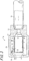
Fig. 4 is an enlarged cross-sectional view illustrating asilencer 17b included in a gas fire-extinguishing apparatus according to yet another embodiment of the invention; -
Fig. 5 is an enlarged cross-sectional view illustrating asilencer 17c included in a gas fire-extinguishing apparatus according to yet another embodiment of the invention; -
Fig. 6 is a cross-sectional view illustrating anejection head 50 of a gas fire-extinguishing apparatus according to yet another embodiment of the invention; -
Fig. 7 is a cross-sectional view explaining an effect of theejection head 50 shown inFig. 6 ; -
Fig. 8 is an enlarged cross-sectional view illustrating asilencer 60 included in a gas fire-extinguishing apparatus according to yet another embodiment of the invention; -
Fig. 9 is an enlarged cross-sectional view illustrating asilencer 60a included in a gas fire-extinguishing apparatus according to yet another embodiment of the invention; -
Fig. 10 is an enlarged cross-sectional view illustrating asilencer 17d included in a gas fire-extinguishing apparatus according to yet another embodiment of the invention; -
Fig. 11 is a graph for explaining a silencing effect by asilencer 17d; -
Fig. 12 is an enlarged cross-sectional view illustrating asilencer 17e included in a gas fire-extinguishing apparatus according to yet another embodiment of the invention; -
Fig. 13 is an enlarged cross-sectional view illustrating asilencer 17f included in a gas fire-extinguishing apparatus according to yet another embodiment of the invention; -
Fig. 14 is an enlarged cross-sectional view illustrating asilencer 17g included in a gas fire-extinguishing apparatus according to yet another embodiment of the invention; -
Fig. 15 is an enlarged cross-sectional view illustrating asilencer 17h included in a gas fire-extinguishing apparatus according to yet another embodiment of the invention; and -
Fig. 16 is a perspective view illustrating a fire-extinguishinggas ejection section 1 used in a gas fire-extinguishing apparatus of the related art. - Now referring to the drawings, preferred embodiments of the invention are described below.
-
Fig. 1 is a perspective view illustrating a fire-extinguishinggas ejection section 11 included in a gas fire-extinguishing apparatus according to an embodiment of the invention. The gas fire-extinguishing apparatus of the embodiment is disposed within a fire-extinguishing area of a building and includes anejection head 13 having anozzle section 12 ejecting high-pressure fire-extinguishing gas into a space within the fire-extinguishing area, aconduit pipe 14, to which theejection head 13 is connected, and guides high-pressure fire-extinguishing gas to theejection head 13, a fire-extinguishinggas supply source 15 supplying high-pressure inert gas to theconduit pipe 14, and asilencer 17 which is disposed on theejection head 13 and attenuates sound generated due to ejection sound or the like by the ejection of the fire-extinguishing gas ejected from anozzle hole 16 which is formed in thenozzle section 12. - The fire-extinguishing gas is realized by an inert gas such as an N2 gas, or a CO2 gas, and an active gas such as a halide gas and such fire-extinguishing gas is ejected as a fire-extinguishing agent so that O2 concentration within the fire-extinguishing area is decreased and thereby the fire can be extinguished.
- The fire-extinguishing
gas ejection section 11 is constituted by theejection head 13 and thesilencer 17. In the fire-extinguishinggas ejection section 11, the fire-extinguishing gas is supplied from the fire-extinguishinggas supply source 15 to theejection head 13 viaconduit pipe 14. Theconduit pipe 14 includes amain pipe 23 connected to the fire-extinguishinggas supply source 15, a divergingpipe 18 interposed in themain pipe 23 and abranch pipe 19 connected to the divergingpipe 18, and the high-pressure fire-extinguishing gas is guided from the fire-extinguishinggas supply source 15 to theejection head 13 via theconduit pipe 14. Theconduit pipe 14 is fastened to abase 20 and abracket 21 by afastener 22 such as a U-bolt, and is disposed on a body of a building in a state where vibration and displacement thereof are suppressed. -
Fig. 2 is an enlarged cross-sectional view of thesilencer 17. Thesilencer 17 includes a cylindricalperipheral wall 25, anend wall 26 which is formed at one end in an axial direction of theperipheral wall 25 to be perpendicular to the axis of theperipheral wall 25, a mountingsection 27 detachably connected to theejection head 13 at the other end in the axial direction of theperipheral wall 25, and a cylindricalsound absorption material 33 accommodated and mounted along an inner peripheral surface of the inside of theperipheral wall 25. Such asound absorption material 33 may be configured by, for example, a laminate of two or more wire meshes. Agas ejection hole 34 is formed in theend wall 26 in the same axial direction. - Since the
silencer 17 configured as described above, is used, the sound vibration caused by the ejection flow of the fire-extinguishing gas ejected in high speed from thenozzle section 12 of theejection head 13 is absorbed by thesound absorption material 33, and the fire-extinguishing gas is ejected from thegas ejection hole 34 to the outside. Accordingly, the occurrence of ejection sound caused by the ejection of the fire-extinguishing gas can be suppressed. -
Fig. 3 is an enlarged cross-sectional view illustrating asilencer 17a included in a gas fire-extinguishing apparatus according to another embodiment of the invention. In addition, portions corresponding to the above-described embodiment are denoted by the same reference numerals. Thesilencer 17a of the embodiment includes a cylindricalperipheral wall 25, theend wall 26 which is formed at one end in the axial direction of theperipheral wall 25 to be perpendicular to the axis of theperipheral wall 25, the mountingsection 27 in which theejection head 13 is integrally formed at the other end in the axial direction of theperipheral wall 25, and aninner cylinder 29 which is disposed in aportion 28 of thenozzle section 12 facing a downstream side in a fire-extinguishing gas ejection direction in thenozzle section 12 of theejection head 13. - The
inner cylinder 29 has aright cylinder section 31 in which a plurality of penetratingholes 30 are formed, and anend plate 32 formed at one end in the axial direction of thecylinder section 31 to be perpendicular to the axial direction of thecylinder section 31. - According to the above-described
silencer 17, within theinner cylinder 29, the fire-extinguishing gas ejected at high speed from the nozzle section of theejection head 13 impacts on thecylindrical end plate 32 of theinner cylinder 29, and is ejected from a plurality of penetratingholes 30 formed on thecylinder section 31, and then the fire-extinguishing gas is ejected to the outside from thegas ejection hole 34 formed in theend wall 26 via a space between thecylinder section 31 and theperipheral wall 25, and the occurrence of sound caused by ejection of the fire-extinguishing gas is suppressed. -
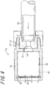
Fig. 4 is an enlarged cross-sectional view illustrating asilencer 17b included in a gas fire-extinguishing apparatus according to yet another embodiment of the invention. Thesilencer 17b of the embodiment includes a cylindricalperipheral wall 35, anend wall 36 which is formed at one end in the axial direction of theperipheral wall 35 to be perpendicular to the axis of theperipheral wall 35, and a mountingsection 37 detachably formed on theejection head 13 at the other end in the axial direction of theperipheral wall 35. A plurality of vent holes 38 are formed in theend wall 36 so as to penetrate theend wall 36 in a thickness direction thereof. - In addition, the
silencer 17b accommodates asound absorption material 40 in aninner space 39 defined by theperipheral wall 35, theend wall 36 and the mountingsection 37. Thesound absorption material 40 may be configured by a laminate of the two or more wire meshes. - According to the gas fire-extinguishing apparatus including the
silencer 17a configured as described above, the fire-extinguishing gas ejected at high speed from thenozzle section 12 of theejection head 13 impacts on theend wall 36 via a space within theperipheral wall 35 and is ejected from the plurality of vent holes 38 formed in theend wall 36 to the outside. The occurrence of large sound can also be prevented from occurring by the above-described configuration of the silencer. -
Fig. 5 is an enlarged cross-sectional view illustrating asilencer 17c included in a gas fire-extinguishing apparatus according to yet another embodiment of the invention. In addition, portions corresponding to the above-described embodiment are denoted by the same reference numerals. Thesilencer 17 of the embodiment includes a cylindricalperipheral wall 41, anend wall 42 which is formed at one end in the axial direction of theperipheral wall 41 to be perpendicular to the axis of theperipheral wall 41, and a mountingsection 43 detachably formed on theejection head 13 at the other end in the axial direction of theperipheral wall 41. A plurality of vent holes 44 are formed in theperipheral wall 41 so as to penetrate theperipheral wall 41 in a thickness direction thereof. - The
silencer 17c configured as described above accommodates asound absorption material 46 in aninner space 45 defined by theperipheral wall 41, theend wall 42 and the mountingsection 43. Thesound absorption material 46 may be configured by, for example, a laminate of two or more wire meshes. - According to the gas fire-extinguishing apparatus including the above-described
silencer 17c, the fire-extinguishing gas ejected from thenozzle section 12 of theejection head 13 impacts on theend wall 42 the flow speed thereof is attenuated, and the fire-extinguishing gas is ejected from a plurality of vent holes 44 formed in theperipheral wall 41 to the outside. Accordingly, the occurrence of large sound caused by the ejection of the fire-extinguishing gas can be prevented. -
Fig. 6 is a cross-sectional view illustrating anejection head 50 of a gas fire-extinguishing apparatus according to yet another embodiment of the invention, andFig. 7 is a cross-sectional view explaining an effect of theejection head 50 shown inFig. 6 . In addition, portions corresponding to the above-described embodiment are denoted by the same reference numerals. The gas fire-extinguishing apparatus of the embodiment is disposed within a building and includes theejection head 50 having thenozzle section 12 ejecting high-pressure fire-extinguishing gas into the space within the building, theconduit pipe 14, to which theejection head 50 is connected and which guides high-pressure fire-extinguishing gas to the ejection head, the fire-extinguishinggas supply source 15 which supplies high-pressure fire-extinguishing gas to theconduit pipe 14. - The
nozzle hole 16 is formed in thenozzle section 12 of theejection head 50, and thenozzle hole 16 has an innerperipheral surface 52 smoothly connected to an innerperipheral surface 51 of thebranch pipe 19 of theconduit pipe 14. - By using the
ejection head 50 configured as described above, the high-pressure fire-extinguishing gas supplied from the fire-extinguishinggas supply source 15 to theconduit pipe 14 is ejected to the space within the building via thenozzle hole 16 of theejection head 50. At this time, since thenozzle hole 16 which has theejection head 50 smoothly connected to the innerperipheral surface 51 of thebranch pipe 19 of theconduit pipe 14, is formed in theejection head 50, the occurrence of large ejection sound can be prevented, wherein the sound is caused by the ejection flow of the fire-extinguishing gas ejected at high speed from thenozzle section 12 of theejection head 50, for example, in anedge section 55 or the like facing the flow-in port of thenozzle hole 16 having an inner diameter D2 smaller than the inner diameter D1 of thebranch pipe 19 of theconduit pipe 14 in anejection head 50a shown inFig. 7 . -
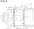
Fig. 8 is an enlarged cross-sectional view illustrating asilencer 60 included in a gas fire-extinguishing apparatus according to yet another embodiment of the invention. In addition, portions corresponding to the above-described embodiment are denoted by the same reference numerals. Thesilencer 60 of the embodiment has a cylindricalperipheral wall 61, a mountingsection 62 which is detachably formed on thebranch pipe 19 at one end in the axial direction of theperipheral wall 61, a mountingsection 63 detachably formed on theejection head 13 at the other end in the axial direction of theperipheral wall 61, anend wall 64 formed at one end in the axial direction of theperipheral wall 61 to be perpendicular to the axis of theperipheral wall 61, and anend wall 65 formed at the other end in the axial direction of theperipheral wall 61 to be perpendicular to the axis of theperipheral wall 61. - At least one of the penetrating
holes 66 is formed in theend wall 64 so as to penetrate theend wall 64 in a thickness direction thereof. The at least one of the penetratingholes 66 is formed in acenter section 68 of theend wall 64, the center of which is on the axis of theperipheral wall 61 and the flow of the fire-extinguishing gas supplied from thebranch pipe 19 is throttled. A plurality of penetratingholes 67 are formed in theend wall 65 so as to penetrate theend wall 65 in a thickness direction thereof. The plurality of penetratingholes 67 are formed in aperipheral section 70 remain except acenter section 69 of theend wall 65 and the center of which is on the axis of theperipheral wall 61. Theend walls - According to the
silencer 60 as described above, the fire-extinguishing gas ejected at high speed from the penetratingholes 66 formed in theend wall 64 impacts on thecenter section 69 of theend wall 65 within thesilencer 60, the flow speed thereof is attenuated and the gas is ejected from the plurality of penetratingholes 67 formed in theend wall 65 within the space defined by theend wall 65 and theejection head 13, and then the gas is ejected from thenozzle hole 16 formed in thenozzle section 12 to the outside. Since thesilencer 60 expands the fire-extinguishing gas ejected at high speed from the penetratingholes 66 formed in theend wall 64 into the space within thesilencer 60, the flow speed thereof is decreased in the penetratingholes 67 formed in theend wall 65 and thereby the occurrence of sound caused by ejection of the fire-extinguishing gas from thenozzle hole 16 can be suppressed. - In the embodiment shown in
Fig. 8 , the penetratingholes 67 are not formed in thecenter section 69 of theend wall 65, however, the penetratingholes 67 may be formed in thecenter section 69 of theend wall 65. The amount of the fire-extinguishing gas ejected at high speed rebounding from the penetratingholes 66 is larger and the flow speed is more decreased in a case where the penetratingholes 67 are not formed in thecenter section 69 of theend wall 65 than those in a case where the penetratingholes 67 are formed in thecenter section 69 of theend wall 65 so that the silencing effect is high. -
Fig. 9 is an enlarged cross-sectional view illustrating asilencer 60a included in a gas fire-extinguishing apparatus according to yet another embodiment of the invention. In addition, portions corresponding to the above-described embodiment are denoted by the same reference numerals. Thesilencer 60a of the embodiment has a cylindricalperipheral wall 61, a mountingsection 62 which is detachably formed on thebranch pipe 19 at one end in the axial direction of theperipheral wall 61, a mountingsection 63 detachably formed on anejection head 13 at the other end in the axial direction of theperipheral wall 61, anend wall 64a formed at one end in the axial direction of theperipheral wall 61 to be perpendicular to the axis of theperipheral wall 61, and anend wall 65 formed at the other end in the axial direction of theperipheral wall 61 to be perpendicular to the axis of theperipheral wall 61. - A
guide section 72 is formed in theend wall 64a so as to be on the axis of theperipheral wall 61 and face an inner space of theperipheral wall 61, wherein theguide section 72 has a plurality of nozzle holes 71 which eject the high-pressure fire-extinguishing gas supplied from thebranch pipe 19 to the inner space defined by theperipheral wall 61 and theend walls guide section 72 are formed to be spaced at equal angles in the axial direction of theperipheral wall 61 and are on an axis thereof orthogonal to the axis of theperipheral wall 61. The plurality of penetratingholes 67 are formed so as to penetrate theend wall 65 in a thickness direction thereof. The plurality of penetratingholes 67 are formed in aperipheral section 70 remaining except thecenter section 69 of theend wall 65, the center of which is on the axis of theperipheral wall 61. Theend wall 65 is made of, for example, the punching metal. In the embodiment shown inFig. 9 , the penetratingholes 67 are not formed in thecenter section 69 of theend wall 65, however, the penetratingholes 67 may be formed in thecenter section 69 of theend wall 65. - According to the
silencer 60a as described above, the fire-extinguishing gas ejected at high speed from the nozzle holes 71 of theguide section 72 formed in theend wall 64a impacts on the inner peripheral surface of theperipheral wall 61 within thesilencer 60a, the flow speed thereof is attenuated, and then the gas is ejected from the plurality of penetratingholes 67 formed in theend wall 65 within the space defined by theend wall 65 and theejection head 13, the gas is ejected from thenozzle hole 16 formed in thenozzle section 12 to the outside. Since thesilencer 60a expands the fire-extinguishing gas ejected at high speed from the nozzle holes 71 into the space within thesilencer 60, the flow speed thereof is decreased in the penetratingholes 67 formed in theend wall 65 and thereby the occurrence of sound caused by ejection of the fire-extinguishing gas from thenozzle hole 16 can be suppressed. -
Fig. 10 is an enlarged cross-sectional view illustrating asilencer 17d included in a gas fire-extinguishing apparatus according to yet another embodiment of the invention. Thesilencer 17d is, for example, attached to anejection head 13 disposed on a wall surface of the fire-extinguishing area to be suitably used. - In addition, portions corresponding to the above-described embodiment are denoted by the same reference numerals. The
silencer 17d of the embodiment has a cylindricalperipheral wall 81, anend wall 82 which is formed at one end in the axial direction of theperipheral wall 81 to be perpendicular to the axis of theperipheral wall 81, and a mountingsection 83 detachably formed on theejection head 13. Thesilencer 17d also includes anend wall 84 formed at the other end in the axial direction of theperipheral wall 81 to be perpendicular to the axis of theperipheral wall 81, abarrier 85 formed between theend wall 82 and theend wall 84 to be perpendicular to the axis of theperipheral wall 81, acylindrical conduction pipe 87 which guides fire-extinguishing gas ejected from theejection head 13 to a silencingchamber 86 which is an inner space defined by theperipheral wall 81, theend wall 82 and thebarrier 85, and acylindrical vent pipe 89 which guides fire-extinguishing gas within a silencingchamber 88 which is the inner space defined by theperipheral wall 81, theend wall 84 and thebarrier 85 to the outside of thesilencer 17d. - The
peripheral wall 81, theend wall 82 and theend wall 84 are made of, for example, the sound absorption material. A plurality of penetratingholes 851 are formed so as to penetrate thebarrier 85 in a thickness direction thereof. Thebarrier 85 is made of, for example, the punching metal. - The
conduction pipe 87 is disposed to penetrate thebarrier 85 and protrude into the silencingchamber 86. Aconnection section 871 which is detachably connected to theejection head 13 is formed at one end in the axial direction of theconduction pipe 87, and anend plate 872 is formed at the other end in the axial direction of theconduction pipe 87. A plurality of penetratingholes 874 are in aportion 873 projected to the silencingchamber 86 of the peripheral wall of theconduction pipe 87 so as to penetrate the peripheral wall of theconduction pipe 87 in a thickness direction thereof. Aportion 873 in which the plurality of penetratingholes 874 of theconduction pipe 87 are formed is made of, for example, the punching metal. Thevent pipe 89 is disposed penetrating thebarrier 85 and theend wall 82, awire mesh 891 is disposed in an opening of the silencingchamber 88 side, and the fire-extinguishing gas is ejected from a fire-extinguishinggas ejection port 892 which is an opening to the outside. The material of thevent pipe 89 is, for example, vinyl chloride. - According to the
silencer 17d as described above, the fire-extinguishing gas ejected at high speed from the plurality of penetratingholes 874 formed in theconduction pipe 87 to the silencingchamber 86 is ejected from the plurality of penetratingholes 851 formed in thebarrier 85 to the silencingchamber 88. The fire-extinguishing gas ejected from the penetratingholes 851 to the silencingchamber 88 is ejected to the outside of thesilencer 17d via avent pipe 89. Thesilencer 17d is configured such that the fire-extinguishing gas ejected at high speed from a plurality of the penetratingholes 874 is expanded in the space within the silencingchamber 86 and in the space within the silencingchamber 88 so that the flow speed thereof is decreased in thevent pipe 89 and the occurrence of sound caused by ejection of the fire-extinguishing gas from thevent pipe 89 can be suppressed.Table 1 Hole diameter (mm) Pressure Flow speed (m/s) Example 1 50 1.5 atmosphere 250 Example 2 80 1.1 atmosphere 100 - Table 1 is a calculation example of the pressure and the flow speed with respect to Examples 1 and 2 of the gas fire-extinguishing apparatus using the
silencer 17d. In Example 1, a hole diameter of thevent pipe 89 of thesilencer 17d is 50 mm, whereas in Example 2, a hole diameter of thevent pipe 89 of thesilencer 17d is 80 mm. The pressure is the pressure of the silencingchamber 86 and the flow speed (m/s) is the flow speed at the fire-extinguishinggas ejection port 892 of thevent pipe 89. - The flow speed when the fire-extinguishing gas at two atmospheres is ejected in the air at one atmosphere, is about 340 m/s, and a large sound occurs. By decreasing the pressure within the silencing
chamber 86, the flow speed at the fire-extinguishinggas ejection port 892 is decreased and the volume of the sound can be decreased. In Example 1, the pressure within the silencingchamber 86 is about 1.5 atmospheres, and the flow speed at the fire-extinguishinggas ejection port 892 is about 250 (m/s). In Example 2, the pressure within the silencingchamber 86 is about 1.1 atmospheres, and the flow speed at the fire-extinguishinggas ejection port 892 is about 100 (m/s). -
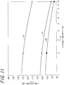
Fig. 11 is a graph for explaining the silencing effect by thesilencer 17d. The vertical axis is the sound pressure (dB) and the horizontal axis is the distance (m) from thenozzle section 12. Thegraph 91 is a graph in a case where the silencer is not used, thegraph 92 is a graph in a case of Example 1 and thegraph 93 is a graph in a case of Example 2. - At a position where the distance from the
nozzle section 12 is 2 (m), in a case where the silencer is not used, the sound pressure is about 125 dB, however, in Example 1, the sound pressure decreases to about 105 dB and in Example 2, the sound pressure decreases to about 100 dB. Similarly, at a position where the distance from thenozzle section 12 is 10 (m), in a case where the silencer is not used, the sound pressure is about 115 dB, however, in Example 1, the sound pressure decreases to about 96 dB and in Example 2, the sound pressure decreases to about 92 dB. In other words, in Example 1, the sound pressure can be decreased by about 20dB and in Example 2, the sound pressure can be decreased by about 25 dB compared to the case where the silencer is not used. -
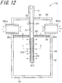
Fig. 12 is an enlarged cross-sectional view illustrating asilencer 17e included in a gas fire-extinguishing apparatus according to yet another embodiment of the invention. Thesilencer 17e is attached to, for example, theejection head 13 disposed on the ceiling of the fire-extinguishing area to be suitably used. In addition, portions corresponding to the above-described embodiment are denoted by the same reference numerals. Thesilencer 17e of the embodiment has the cylindricalperipheral wall 81, theend wall 82 formed at one end in the axial direction of theperipheral wall 81 to be perpendicular to the axis of theperipheral wall 81, and a mountingsection 83 detachably formed on theejection head 13. Thesilencer 17e also includes anend wall 84 formed at the other end in the axial direction of theperipheral wall 81 to be perpendicular to the axis of theperipheral wall 81, thebarrier 85 formed between theend wall 82 and theend wall 84 to be perpendicular to the axis of theperipheral wall 81, acylindrical conduction pipe 87 which guides fire-extinguishing gas ejected from theejection head 13 to a silencingchamber 86 which is an inner space defined by theperipheral wall 81, theend wall 82 and thebarrier 85, and a plurality ofcylindrical vent holes 89a which guide the fire-extinguishing gas within a silencingchamber 88 which is the inner space defined by theperipheral wall 81, theend wall 84 and thebarrier 85 to the outside of thesilencer 17e. - The
peripheral wall 81, theend wall 82 and theend wall 84 are for example, made of the sound absorption material. The plurality of penetratingholes 851 are formed so as to penetrate thebarrier 85 in a thickness direction thereof. Thebarrier 85 is made of, for example, the punching metal. - The
conduction pipe 87 penetrates thebarrier 85 and is disposed to protrude to the silencingchamber 86. Theconnection section 871 which is detachably connected to theejection head 13 is formed at one end in the axial direction of theconduction pipe 87, and theend plate 872 is formed at the other end in the axial direction of theconduction pipe 87. The plurality of penetratingholes 874 are formed in theportion 873 which is projected to the silencingchamber 86 of the peripheral wall of theconduction pipe 87 so as to penetrate the peripheral wall of theconduction pipe 87 in a thickness direction thereof. Theportion 873 in which the plurality of penetratingholes 874 of theconduction pipe 87 are formed is made of, for example, the punching metal. The plurality ofvent pipes 89a are disposed to be spaced at equal angles in the peripheral direction with respect to the axis of theperipheral wall 81 and are on an axis orthogonal to the axis of theperipheral wall 81 which is formed so as to penetrate theperipheral wall 81 respectively. A fire-extinguishinggas ejection port 892a which is an opening to the outside of thesilencer 17e is formed in eachvent pipe 89a and the fire-extinguishing gas ejects from each fire-extinguishinggas ejection port 892a to the outside of thesilencer 17e. The material of thevent pipes 89a for example, is vinyl chloride. - According to the
silencer 17e as described above, the fire-extinguishing gas is ejected from the plurality of penetratingholes 851 formed in thebarrier 85 to the silencingchamber 88, wherein the fire-extinguishing gas ejected at high speed from the plurality of penetratingholes 874 formed in theconduction pipe 87 to the silencingchamber 86. The fire-extinguishing gas ejected from the penetratingholes 851 to the silencingchamber 88 is ejected to the outside of thesilencer 17e via thevent pipes 89a. Since thesilencer 17e is configured such that the fire-extinguishing gas ejected at high speed from the plurality of penetratingholes 874 is expanded in the space within the silencingchamber 86 and the space within the silencingchamber 88 so that the flow speed in thevent holes 89a is decreased, the occurrence of sound caused by ejection of the fire-extinguishing gas from thevent pipes 89a is suppressed. -
Fig. 13 is an enlarged cross-sectional view illustrating asilencer 17f included in a gas fire-extinguishing apparatus according to yet another embodiment of the invention. In addition, portions corresponding to the above-described embodiment are denoted by the same reference numerals. Thesilencer 17f is, for example, attached to theejection head 13 disposed on the wall surface of the fire-extinguishing area to be suitably used. - The
silencer 17f of the embodiment has a cylindricalperipheral wall 121, an annular theend wall 122 formed at one end in the axial direction of theperipheral wall 121 to be perpendicular to the axis of theperipheral wall 121, and a mountingsection 123 formed at the other end in the axial direction of theperipheral wall 121 and detachably formed on theejection head 13. A silencingchamber 124 is formed in thesilencer 17f wherein the silencingchamber 124 is an inner space defined by theejection head 13, theperipheral wall 121 and theend wall 122. A columnarsound absorption material 125 is mounted along the inner peripheral surface of theperipheral wall 121 and accommodated in the silencingchamber 124. Acasing 129 is constituted by theperipheral wall 121, theend wall 122 and the mountingsection 123. - A inner
peripheral surface 121 a of theperipheral wall 121 facing the silencingchamber 124 of thecasing 129 is cylindrically formed and aninner surface 122a of theend wall 122 facing the silencingchamber 124 is formed on an imaginary plane perpendicular to an axis L121 of theperipheral wall 121. A penetratinghole 122b is formed so as to penetrate theend wall 122 in a direction of the axis L121, the center of which is on the axis L121 of theperipheral wall 121. - The
sound absorption material 125 is formed in a columnar shape and an outerperipheral surface 125a of which is formed in a cylindrical shape. Anend surface 125b of one side of thesound absorption material 125 in a direction of an axis L125 of thesound absorption material 125 and anend surface 125c of the other side are formed on an imaginary plane perpendicular to the axis L125. Anend surface 12a of thenozzle section 12 of theejection head 13 on the downstream side of the fire-extinguishing gas ejection direction is formed on an imaginary plane perpendicular to an axis L12 of thenozzle section 12. - The
silencer 17f is charged in the space within thecasing 129 from the mountingsection 123 in a posture in which the axis L125 of thesound absorption material 125 is aligned or substantially aligned with the axis L121 of theperipheral wall 121. For example, if thesound absorption material 125 is a right cylindrical shape, thesound absorption material 125 is detachably configured by screwing an outside screw threaded in the outer peripheral portion of thenozzle section 12 on the downstream side of the fire-extinguishing gas ejection direction to an inside screw threaded in the inner peripheral portion of the mountingsection 123. In thesilencer 17f, thesound absorption material 125 is accommodated in the silencingchamber 124 in a state where one side theend surface 125b and theinner surface 122a of theend wall 122 are surface-contacted with each other and the other side theend surface 125c and theend surface 12a of thenozzle section 12 are surface-contacted with each other. In other words, thesound absorption material 125 fills the silencingchamber 124 without a gap. In the embodiment, the hole diameter of the penetratinghole 122b is formed in a size that the fire-extinguishing agent can be effectively ejected. In addition, the effective hole diameter portion of the penetratinghole 122b may be not only on the end wall surface side but also on the peripheral wall surface side. Since the effective area of the portion of the end wall surface side can be decreased by disposing the effective hole diameter portion in the peripheral wall surface, thesilencer 17f can be decreased in size. In addition, thesilencer 17f can also be decreased in size by charging thesound absorption material 125 in the space within thecasing 129 without a gap. - The
sound absorption material 125 is made of the porous metal in which columnar air gaps are continuous. Since thesilencer 125 as described above, is disposed immediately after thenozzle hole 16, thesilencer 17f gradually expands the fire-extinguishing gas supplied from thebranch pipe 19 with the decreased pressure and the flow speed thereof can be decreased. Accordingly, the occurrence of ejection sound caused by the ejection of the fire-extinguishing gas can be suppressed. - Specifically, since the
sound absorption material 125 fills the silencingchamber 124 without a gap, the fire-extinguishing gas ejected from thenozzle hole 16 can be directly flowed in the porous metal which is thesound absorption material 125 and the fire-extinguishing gas flowed in the porous metal can be directly ejected from the penetratinghole 122b. As described above, since the fire-extinguishing gas ejected from thenozzle hole 16 is directly flowed in thesound absorption material 125, the fire-extinguishing gas is excessively expanded immediately after being ejected from thenozzle hole 16 and the fire-extinguishing gas is flowed in thesound absorption material 125 before a shock wave is generated and thereby the fire-extinguishing gas is decelerated and spreads rapidly. Accordingly, the occurrence of strong turbulence with the shock wave is prevented and noise is suppressed. In addition, since the fire-extinguishing gas is dispersed by the fine air gaps of thesound absorption material 125, the flow speed of the fire-extinguishing gas ejected from thesound absorption material 125 to the outside via penetratinghole 122b is attenuated, and thereby the noise is also suppressed without a large shock wave being generated. Thus, rapid expansion of the fire-extinguishing gas with the decreased pressure can be suppressed compared to a case where theend surface 12a of thenozzle section 12 is separated from theend surface 125c of thesound absorption material 125, and further rapid expansion of the fire-extinguishing gas with the decreased pressure can be suppressed compared to a case where theinner surface 122a of an end wall 111 is separated from theend surface 125b of thesound absorption material 125. - As described above, since the
silencer 17f of the embodiment is gradually expanded with decreased pressure by the porous metal which is thesound absorption material 125 and the flow speed can be decreased, the occurrence of ejection sound caused by the ejection of the fire-extinguishing gas can be suppressed. Furthermore, since thesilencer 17f is configured to suppress rapid expansion of the fire-extinguishing gas with decreased pressure, the occurrence of noise caused by the rapid expansion with decreased pressure can be suppressed. -
Fig. 14 is an enlarged cross-sectional view illustrating asilencer 17g included in a gas fire-extinguishing apparatus according to yet another embodiment of the invention. In addition, portions corresponding to the above-described embodiment are denoted by the same reference numerals. In the embodiment, thesilencer 17g is mounted for example, on theejection head 13 disposed in a wall surface of the fire-extinguishing area. - The
silencer 17g of the embodiment has a cylindricalperipheral wall 131, anend wall 132 formed at the other end in the axial direction of theperipheral wall 131 to be perpendicular to the axis of theperipheral wall 131, and a mountingsection 133 continuously formed in theend wall 132 and detachably formed on theejection head 13. An inside screw is threaded in the inner peripheral surface of theperipheral wall 131 at one end in the axial direction. A silencingchamber 140 which is an inner space defined by theperipheral wall 131, theend wall 132 and theejection head 13 is formed in thesilencer 17g. - The silencing
chamber 140 accommodates a columnar firstsound absorption material 134 disposed at one end in the axial direction of the peripheral wall, a columnar secondsound absorption material 135 disposed at the other end in the axial direction of the peripheral wall, a cylindrical thirdsound absorption material 136 disposed between the firstsound absorption material 134 and the secondsound absorption material 135, anannular end plate 141 supporting the firstsound absorption material 134, anannular spacer 142, and anut 143. - The first
sound absorption material 134 and the secondsound absorption material 135 are made of planar columnar porous metal. The firstsound absorption material 134 is accommodated as mounting at one end in the axial direction of theperipheral wall 131 along the inner peripheral surface and disposed in contact with one surface facing the silencingchamber 140 of theend wall 132 and one end in the axial direction of theejection head 13. - An
annular end plate 141 having a penetratinghole 141 a is disposed at one end in the axial direction of the firstsound absorption material 134. Theend plate 141 is disposed in contact with the firstsound absorption material 134 and regulates the movement of the firstsound absorption material 134 to one end thereof in the axial direction. The thirdsound absorption material 136 is disposed at one end in the axial direction of theend plate 141. In the embodiment, the thirdsound absorption material 136 is realized by the same member as thesound absorption material 33 of the above-describedsilencer 17. In addition, the thirdsound absorption material 136 may be realized by the porous metal. The thirdsound absorption material 136 is accommodated to be mounted along the inner peripheral surface of theperipheral wall 131. - An
annular spacer 142 having a penetratinghole 142a is disposed at one end in the axial direction of the thirdsound absorption material 136. Thespacer 142 is disposed in contact with the secondsound absorption material 135 and holds the interval between the thirdsound absorption material 136 and the secondsound absorption material 135. - The second
sound absorption material 135 is disposed at one end in the axial direction of thespacer 142. In the embodiment, the secondsound absorption material 135 may be formed in the same shape as the firstsound absorption material 134 and may be formed differently from the firstsound absorption material 134. The secondsound absorption material 135 is accommodated to be mounted along the inner peripheral surface of theperipheral wall 131. - The
nut 143 is disposed at one end in the axial direction of the secondsound absorption material 135. An outside screw is threaded in the outer peripheral portion of thenut 143 and thenut 143 is fastened in a screwed state to an inside screw threaded in the inner peripheral portion of an opening end side of theperipheral wall 131, and thenut 143 supports the secondsound absorption material 135 while pressing it against the other end side in the axial direction thereof. Accordingly, each of thesound absorption materials end plate 141 and thespacer 142 are regulated to be displaced to one end side in the axial direction thereof. - According to the embodiment, the
silencer 17g is disposed as accommodating three sound absorption materials. As described above, since the firstsound absorption material 134 is disposed immediately after thenozzle hole 16, thesilencer 17g is configured such that the fire-extinguishing gas supplied from thebranch pipe 19 side is gradually expanded with decreased pressure and the flow speed thereof can be decreased. In addition, since the thirdsound absorption material 136 is disposed, the sound vibration caused by the ejection flow of the fire-extinguishing gas is absorbed by the thirdsound absorption material 136 and thereby the occurrence of ejection sound caused by the ejection of the fire-extinguishing gas can be suppressed. In addition, since the secondsound absorption material 135 is disposed, the fire-extinguishing gas passing the thirdsound absorption material 136 can further decrease the pressure and the flow speed thereof can be decreased. Accordingly, the occurrence of ejection sound caused by the ejection of the fire-extinguishing gas can be suppressed. -
Fig. 15 is an enlarged cross-sectional view illustrating asilencer 17h included in a gas fire-extinguishing apparatus according to yet another embodiment of the invention. In addition, portions corresponding to the above described embodiment are denoted by the same reference numerals. In the embodiment, thesilencer 17h is mounted, for example, on thebranch pipe 19 disposed in a wall surface of the fire-extinguishing area via anejection head 13. - The
silencer 17h of the embodiment includes theejection head 13, a bottomedcylindrical casing 150, anut 151 which is screwed to an opening of thecasing 150, a cylindrical firstsound absorption material 152 mounted on theejection head 13, a cylindrical secondsound absorption material 153 accommodated in thecasing 150 and disposed along the inner peripheral surface of thecasing 150, an annular-shaped first supportingpiece 154 mounted on a base end section of theejection head 13 within thecasing 150, a disk-shaped second supportingpiece 155 disposed in contact with the end surface of theejection head 13 on the opening side within thecasing 150, and a disk-shaped thirdsound absorption material 156 held in a supported state in the opening of thecasing 150 by thenut 151. - The
casing 150 has a rightcylindrical section 157, aflange section 158 projecting perpendicularly from one end in the axial direction of thecylindrical section 157 radially and outwardly, and an annular theend wall 159 extending from the other end in the axial direction of thecylindrical section 157 radially and inwardly. Anoutside screw 160 is threaded in an outer peripheral portion of theflange section 158. Aninsertion hole 161 is formed in theend wall 159 in which the base end section of theejection nozzle 13 is inserted on the center axis thereof. Thecasing 150 as described above, is made of metal. In addition, the first to the thirdsound absorption materials - The
nut 151 has a rightcylindrical section 162 and aflange section 163 projecting from one end in the axial direction of thecylindrical section 162 radially and inwardly. Aninside screw 164 is threaded in the inner peripheral surface of the other end in the axial direction of thecylindrical section 162 and screwed to anoutside screw 160 of thecasing 150. Thenut 151, as described above, is made of metal. Thenut 151 is screwed to theoutside screw 160 of thecasing 150 so that the peripheral section of the thirdsound absorption material 156 is pinched by theflange section 158 of thecasing 150 and theflange section 163 of thenut 151, and at the same time, the second supportingpiece 155 is pinched by the thirdsound absorption material 156 and theend wall 165 of theejection head 13, and thereby ejection thereof from thecasing 150 of a secondsound absorption material 153 is prevented. - The
ejection head 13 has an engagingsection 166 in which a fastening tool such as spanner is engaged, acylindrical section 167 extended to the engagingsection 166 in the axial direction thereof, and theend wall 165 which closes one end in the axial direction of thecylindrical section 167. The nozzle holes 16 are formed in thecylindrical section 157 so as to penetrate in a thickness direction thereof at intervals of, for example, every 90° in a peripheral direction thereof. Anoutside screw 168 is threaded in the base section near the engagingsection 166 of thecylindrical section 167. Aninside screw 169 threaded in the inner peripheral surface of the first supportingpiece 154 is screwed to theoutside screw 168 and theend wall 159 of thecasing 150 is pinched by the second supportingpiece 155 and the engagingsection 166, and theejection head 13 is fixed to thecasing 150 on the same axis. As described above, in a state where the firstsound absorption material 152 is mounted on theejection head 13, in other words, in a state where the firstsound absorption material 152 is mounted on thecylindrical section 12 within thecasing 150, the firstsound absorption material 152 is held in a pinched state by the first and the second supportingpieces silencer 17h as described above, anannular space 170 is formed between the firstsound absorption material 152 and the secondsound absorption material 153 through theend wall 159 of thecasing 150 and the thirdsound absorption material 156. - The high-pressure fire-extinguishing gas supplied from the
branch pipe 19 to theejection head 13 is ejected from each thenozzle hole 16 of theejection head 13 within the firstsound absorption material 152, and the shock wave thereof is rapidly dispersed and decelerated, so that the occurrence of strong turbulence with the shock wave is prevented and the sound can be decreased. The fire-extinguishing gas ejected from the firstsound absorption material 152 to thespace 170 enters the secondsound absorption material 153 and thereby the gas rapidly dispersed and decelerated similar to the firstsound absorption material 152, and is reflected by the inner peripheral surface of thecasing 150 and directed to the thirdsound absorption material 156. The fire-extinguishing gas having entered the thirdsound absorption material 156 is dispersed and decelerated before being rapidly expanded similar to the above-described first and secondsound absorption materials - In the embodiment shown in
Fig. 15 , the plurality ofejection nozzles 16 are formed in thecylindrical section 12 of theejection head 13 to be perpendicular to the axial direction thereof and thereby the fire-extinguishing gas is ejected radially and outwardly, however, in yet another embodiment of the invention, the nozzle holes 16 inclined to the opening of thecasing 150 may be formed in the cylindrical section of theejection head 13 and thereby the gas passing the firstsound absorption material 152 may be ejected to the thirdsound absorption material 156 as it is. Even such constitution can obtain the same advantage. - The invention may be embodied in other specific forms without departing from the spirit or essential characteristics thereof. The present embodiments are therefore to be considered in all respects as illustrative and not restrictive, the scope of the invention being indicated by the appended claims rather than by the foregoing description and all changes which come within the meaning and the range of equivalency of the claims are therefore intended to be embraced therein.
-
- 11:
- Gas ejection section
- 12:
- Nozzle section
- 13, 50, 50a:
- Ejection head
- 14:
- Conduit pipe
- 15:
- Fire-extinguishing gas supply source
- 16, 71:
- Nozzle hole
- 17, 17a-17h, 60, 60a:
- Silencer
- 18:
- Diverging pipe
- 19:
- Branch pipe
- 20:
- Base
- 21:
- Bracket
- 22:
- Fastener
- 23:
- Main pipe
- 25, 35, 41, 61, 81:
- Peripheral wall
- 26, 36, 42, 64, 64a, 65, 82, 84:
- End wall
- 27, 37, 43, 62, 63, 83, 123:
- Mounting section
- 28:
- Portion facing downstream side in ejection direction
- 29:
- Inner cylinder
- 30, 66, 67, 851, 874:
- Penetrating hole
- 31:
- Cylinder section
- 32, 872:
- End plate
- 33:
- Sound absorption material
- 34:
- Gas ejection hole
- 38, 44:
- Vent hole
- 39, 45:
- Inner space
- 40, 46:
- Sound absorption material
- 51, 52:
- Inner peripheral surface
- 55:
- Edge section
- 72:
- Guide section
- 85:
- Barrier
- 86, 88:
- Silencing chamber
- 87:
- Conduction pipe
- 89, 89a:
- Vent pipe
- 125:
- Sound absorption material
- 134:
- First sound absorption material
- 135:
- Second sound absorption material
- 136:
- Third sound absorption material
- 871:
- Connection section
- 891:
- Wire mesh
- 892, 892a:
- Fire-extinguishing gas ejection port
- D1, D2:
- Inner diameter
Claims (6)
- A gas fire-extinguishing apparatus, comprising:an ejection head having a nozzle section which ejects high-pressure fire-extinguishing gas to a space;a conduit pipe which is connected to the ejection head and guides high-pressure fire-extinguishing gas to the ejection head; anda fire-extinguishing gas supply source which supplies the high-pressure fire-extinguishing gas to the conduit pipe,a nozzle hole which is formed in the nozzle section of the ejection head and has an inner peripheral surface smoothly connected to an inner peripheral surface of the conduit pipe.
- A gas fire-extinguishing apparatus, comprising:an ejection head having a nozzle section which ejects high-pressure fire-extinguishing gas to a space;a conduit pipe which is connected to the ejection head and guides high-pressure fire-extinguishing gas to the ejection head;a fire-extinguishing gas supply source which supplies the high-pressure fire-extinguishing gas to the conduit pipe; anda silencer which is disposed on the ejection head and attenuates sound caused by ejection of the fire-extinguishing gas from the nozzle section,wherein the silencer comprises a cylindrical peripheral wall, a first end wall formed at one end in an axial direction of the peripheral wall to be perpendicular to an axis of the peripheral wall, a second end wall having a mounting section which is detachably formed on the ejection head at the other end in the axial direction of the peripheral wall to be perpendicular to the axis of the peripheral wall, a barrier formed between the first end wall and the second end wall to be perpendicular to the axis of the peripheral wall, a cylindrical conduction pipe which guides fire-extinguishing gas ejected from the ejection head to a first silencing chamber which is an inner space defined by the peripheral wall, the first end wall and the barrier, and a cylindrical vent pipe which guides fire-extinguishing gas within a second silencing chamber which is an inner space defined by the peripheral wall, the second end wall and the barrier,a plurality of penetrating holes are formed in the barrier so as to penetrate the barrier in a thickness direction thereof,a connection section which is detachably connected to the ejection head is formed at one end in an axial direction of the conduction pipe, an end plate is formed at the other end in the axial direction of the conduction pipe, and the plurality of penetrating holes are in a portion projected to the first silencing chamber of the peripheral wall of the conduction pipe so as to penetrate the peripheral wall of the conduction pipe in a thickness direction thereof, andthe vent pipe is disposed to penetrate the barrier and the first end wall.
- A gas fire-extinguishing apparatus, comprising:an ejection head having a nozzle section which ejects high-pressure fire-extinguishing gas to a space;a conduit pipe which is connected to the ejection head and guides high-pressure fire-extinguishing gas to the ejection head;a fire-extinguishing gas supply source which supplies the high-pressure fire-extinguishing gas to the conduit pipe; anda silencer which is disposed on the ejection head and attenuates sound caused by ejection of the fire-extinguishing gas from the nozzle section,wherein the silencer comprises a cylindrical peripheral wall, a first end wall formed at one end in an axial direction of the peripheral wall to be perpendicular to an axis of the peripheral wall, a second end wall having a mounting section which is detachably formed on the ejection head at the other end in the axial direction of the peripheral wall to be perpendicular to the axis of the peripheral wall, a barrier formed between the first end wall and the second end wall to be perpendicular to the axis of the peripheral wall, a cylindrical conduction pipe which guides fire-extinguishing gas ejected from the ejection head to a first silencing chamber which is an inner space defined by the peripheral wall, the first end wall and the barrier, and a plurality of cylindrical vent pipes which guide the fire-extinguishing gas within a second silencing chamber which is an inner space defined by the peripheral wall, the second end wall and the barrier to an outside,a plurality of penetrating holes are formed so as to penetrate the barrier in a thickness direction thereof,a connection section which is detachably connected to the ejection head is formed at one end in an axial direction of the conduction pipe, an end plate is formed at the other end in the axial direction of the conduction pipe, and the plurality of penetrating holes are in a portion projected to the first silencing chamber of the peripheral wall of the conduction pipe so as to penetrate the peripheral wall of the conduction pipe in a thickness direction thereof, andthe plurality of vent pipes are disposed to be spaced at equal angles in a peripheral direction with respect to the axis of the peripheral wall and are on an axis orthogonal to the axis of the peripheral wall and are formed so as to penetrate each peripheral wall.
- A gas fire-extinguishing apparatus, comprising:an ejection head having a nozzle section which ejects high-pressure fire-extinguishing gas to a space;a conduit pipe which is connected to the ejection head and guides high-pressure fire-extinguishing gas to the ejection head;a fire-extinguishing gas supply source which supplies the high-pressure fire-extinguishing gas to the conduit pipe; anda silencer which is disposed on the ejection head and attenuates sound caused by ejection of the fire-extinguishing gas from the nozzle section,wherein the silencer comprisesa cylindrical peripheral wall,an end wall formed at one end in an axial direction of the peripheral wall to be perpendicular to an axis of the peripheral wall,a mounting section detachably formed on the ejection head, anda sound absorption material which is accommodated in an inner space defined by the peripheral wall, the end wall and the ejection head, and made of a porous metal.
- The gas fire-extinguishing apparatus of claim 4, wherein, the sound absorption material comprises a first sound absorption material disposed at one end in the axial direction of the peripheral wall and a second sound absorption material disposed at the other end in the axial direction of the peripheral wall.
- The gas fire-extinguishing apparatus of claim 5, wherein the silencer further comprises a third sound absorption material disposed between the first sound absorption material and the second sound absorption material.
Applications Claiming Priority (6)
| Application Number | Priority Date | Filing Date | Title |
|---|---|---|---|
| JP2009244986 | 2009-10-23 | ||
| JP2010023575 | 2010-02-04 | ||
| JP2010086586 | 2010-04-02 | ||
| JP2010161096A JP5276630B2 (en) | 2009-10-23 | 2010-07-15 | Gas fire extinguishing equipment |
| PCT/JP2010/068087 WO2011049002A1 (en) | 2009-10-23 | 2010-10-14 | Gas fire-extinguishing facility |
| EP10824851.9A EP2491984B1 (en) | 2009-10-23 | 2010-10-14 | Gas fire-extinguishing facility |
Related Parent Applications (2)
| Application Number | Title | Priority Date | Filing Date |
|---|---|---|---|
| EP10824851.9A Division EP2491984B1 (en) | 2009-10-23 | 2010-10-14 | Gas fire-extinguishing facility |
| EP10824851.9A Division-Into EP2491984B1 (en) | 2009-10-23 | 2010-10-14 | Gas fire-extinguishing facility |
Publications (4)
| Publication Number | Publication Date |
|---|---|
| EP3243552A2 true EP3243552A2 (en) | 2017-11-15 |
| EP3243552A3 EP3243552A3 (en) | 2018-02-21 |
| EP3243552C0 EP3243552C0 (en) | 2024-03-06 |
| EP3243552B1 EP3243552B1 (en) | 2024-03-06 |
Family
ID=43900229
Family Applications (2)
| Application Number | Title | Priority Date | Filing Date |
|---|---|---|---|
| EP10824851.9A Active EP2491984B1 (en) | 2009-10-23 | 2010-10-14 | Gas fire-extinguishing facility |
| EP17178419.2A Active EP3243552B1 (en) | 2009-10-23 | 2010-10-14 | Gas fire-extinguishing apparatus |
Family Applications Before (1)
| Application Number | Title | Priority Date | Filing Date |
|---|---|---|---|
| EP10824851.9A Active EP2491984B1 (en) | 2009-10-23 | 2010-10-14 | Gas fire-extinguishing facility |
Country Status (6)
| Country | Link |
|---|---|
| US (1) | US9457214B2 (en) |
| EP (2) | EP2491984B1 (en) |
| JP (1) | JP5276630B2 (en) |
| KR (2) | KR101412253B1 (en) |
| CN (3) | CN102573998B (en) |
| WO (1) | WO2011049002A1 (en) |
Families Citing this family (29)
| Publication number | Priority date | Publication date | Assignee | Title |
|---|---|---|---|---|
| JP4988945B2 (en) * | 2009-10-23 | 2012-08-01 | エア・ウォーター防災株式会社 | Gas fire extinguishing equipment |
| JP5276630B2 (en) | 2009-10-23 | 2013-08-28 | エア・ウォーター防災株式会社 | Gas fire extinguishing equipment |
| JP5972518B2 (en) * | 2009-11-02 | 2016-08-17 | 株式会社コーアツ | Ejection head with a sound deadening function for gas fire extinguishing equipment |
| JP2011120797A (en) * | 2009-12-11 | 2011-06-23 | Air Water Safety Service Inc | Fire extinguishing gas jetting device |
| US8887820B2 (en) * | 2011-05-12 | 2014-11-18 | Fike Corporation | Inert gas suppression system nozzle |
| TWI566804B (en) * | 2012-02-21 | 2017-01-21 | 高壓股份有限公司 | Injection head having silencing function for gas-type fire extinguisher |
| JP5276730B1 (en) * | 2012-03-21 | 2013-08-28 | 株式会社コーアツ | Ejection head with a sound deadening function for gas fire extinguishing equipment |
| JP5276728B1 (en) * | 2012-02-21 | 2013-08-28 | 株式会社コーアツ | Ejection head with a sound deadening function for gas fire extinguishing equipment |
| US9597537B2 (en) | 2012-05-03 | 2017-03-21 | Koatsu Co., Ltd. | Injection head having silencing function for gas type fire extinguisher |
| JP5989591B2 (en) * | 2013-04-17 | 2016-09-07 | 株式会社コーアツ | Ejection head with a sound deadening function for gas fire extinguishing equipment |
| JP6305688B2 (en) * | 2013-04-17 | 2018-04-04 | 株式会社コーアツ | Ejection head with a sound deadening function for gas fire extinguishing equipment |
| JP6196955B2 (en) * | 2013-10-02 | 2017-09-13 | エア・ウォーター防災株式会社 | Fire extinguishing gas jetting apparatus and gas fire extinguishing apparatus provided with the same |
| KR102108374B1 (en) | 2013-10-25 | 2020-05-08 | 삼성전자주식회사 | Stroage system and method for analyzing non-signal thereof |
| GB2543357A (en) * | 2015-10-16 | 2017-04-19 | Graviner Ltd Kidde | Fire supression systems |
| US10507343B2 (en) * | 2015-12-04 | 2019-12-17 | Tyco Fire Products Lp | Low pressure drop acoustic suppressor nozzle for fire protection inert gas discharge system |
| WO2017096261A1 (en) * | 2015-12-04 | 2017-06-08 | Tyco Fire Products Lp | Low pressure drop acoustic suppressor nozzle for inert gas discharge system |
| CN105641841A (en) * | 2016-01-25 | 2016-06-08 | 维梯埃消防设备(上海)有限公司 | Silencing device |
| WO2017216851A1 (en) * | 2016-06-13 | 2017-12-21 | 株式会社コーアツ | Fire extinguisher |
| CN106247037A (en) * | 2016-08-25 | 2016-12-21 | 吴速 | A kind of firing-fighting medium conveyer belt and quickly take-off reel |
| KR102620362B1 (en) * | 2016-08-31 | 2024-01-04 | 삼성전자주식회사 | Air conditioner |
| JP6779735B2 (en) * | 2016-10-07 | 2020-11-04 | ニッタン株式会社 | Gas discharge nozzle for gas fire extinguishing equipment |
| EP3311886A1 (en) * | 2016-10-20 | 2018-04-25 | Siemens Schweiz AG | Muffled extinguishing nozzle assembly having a frequency selective noise dampening coating as well as suitable use |
| EP3560557B1 (en) * | 2016-12-26 | 2024-02-28 | Koatsu Co., Ltd. | Jet head having silencing function for gas-based fire extinguishing equipment, and method for storing and assembling same |
| CN113413566A (en) * | 2017-05-19 | 2021-09-21 | 株式会社高压 | Spray head for liquefied fire extinguishing agent |
| US11117007B2 (en) * | 2017-11-10 | 2021-09-14 | Carrier Corporation | Noise reducing fire suppression nozzles |
| TWI799647B (en) * | 2018-10-02 | 2023-04-21 | 日商高壓股份有限公司 | Nozzles for liquid fire extinguishing agents |
| CN114599430A (en) * | 2019-08-09 | 2022-06-07 | 泰科消防产品有限合伙公司 | Fire suppression nozzle and system |
| EP4096797A1 (en) * | 2020-01-31 | 2022-12-07 | Carrier Corporation | Low noise discharge nozzle |
| US20210291000A1 (en) * | 2020-03-20 | 2021-09-23 | Kidde Technologies, Inc. | Fire suppression systems and methods of controlling flow of fire suppressant agents in fire suppression systems |
Citations (1)
| Publication number | Priority date | Publication date | Assignee | Title |
|---|---|---|---|---|
| JPH08173565A (en) | 1994-12-22 | 1996-07-09 | Koatsu:Kk | Fire extinguishing method for inert gas fire extinguisher and equipment thereof |
Family Cites Families (61)
| Publication number | Priority date | Publication date | Assignee | Title |
|---|---|---|---|---|
| US1844104A (en) * | 1929-05-08 | 1932-02-09 | Burgess Lab Inc C F | Exhaust muffler |
| US1844105A (en) | 1929-05-08 | 1932-02-09 | Burgess Lab Inc C F | Exhaust muffler |
| US1844106A (en) | 1929-05-08 | 1932-02-09 | Burgess Lab Inc C F | Exhaust muffler |
| US1811762A (en) | 1929-05-08 | 1931-06-23 | Burgess Lab Inc C F | Exhaust muffler |
| US2030017A (en) | 1930-09-26 | 1936-02-04 | Mile Raymond | Automatic smoke preventer |
| US1968456A (en) | 1932-07-28 | 1934-07-31 | Burgess Lab Inc C F | Gaseous pressure wave absorbing construction |
| US2376933A (en) | 1943-01-04 | 1945-05-29 | Stone Wheel Inc | Spark and flame arrestor |
| US2442773A (en) * | 1944-05-05 | 1948-06-08 | Bell Telephone Labor Inc | Sound suppressor |
| US2559408A (en) * | 1946-10-11 | 1951-07-03 | Pyrene Mfg Co | Fire extinguisher nozzle for vehicles |
| US2600236A (en) * | 1948-11-16 | 1952-06-10 | Esther Larsen | Muffler with a plurality of passages |
| US2792760A (en) * | 1954-03-26 | 1957-05-21 | Hammer Alexander | Combination flash eliminator and stabilizer for a firearm |
| US3339668A (en) | 1965-03-18 | 1967-09-05 | C W Morris Company | Air exhaust noise attenuator |
| US3672465A (en) * | 1970-10-15 | 1972-06-27 | Blatt Leland F | Gas exhaust silencer |
| US3960239A (en) | 1973-08-15 | 1976-06-01 | Barry Wright Corporation | Noise-reducing fluid-flow devices |
| JPS515799U (en) | 1974-06-29 | 1976-01-16 | ||
| US3949828A (en) | 1974-08-30 | 1976-04-13 | Barry Wright Corporation | Fluid exhaust silencer |
| JPS5512824Y2 (en) * | 1975-08-05 | 1980-03-22 | ||
| JPS6033544B2 (en) | 1977-03-17 | 1985-08-03 | 株式会社豊田中央研究所 | Pressure fluid release device for low noise |
| JPS5644423Y2 (en) | 1978-07-12 | 1981-10-17 | ||
| JPS56161110U (en) | 1980-04-30 | 1981-12-01 | ||
| JPS58103100U (en) * | 1982-01-06 | 1983-07-13 | 横河電機株式会社 | Silencer for air purge |
| JPS5933450U (en) | 1982-08-25 | 1984-03-01 | ニツタン株式会社 | Silencer for gas discharge pipe for testing gas fire extinguishing equipment |
| JPS60175718A (en) * | 1984-02-22 | 1985-09-09 | Nippon Soken Inc | Muffler for internal combustion engine |
| JPH0332736Y2 (en) * | 1985-03-22 | 1991-07-11 | ||
| JPH0640896Y2 (en) * | 1987-11-13 | 1994-10-26 | 日酸運輸株式会社 | silencer |
| SU1657679A1 (en) | 1989-02-28 | 1991-06-23 | Московский автомеханический институт | Gas jet silencer |
| US5250094A (en) | 1992-03-16 | 1993-10-05 | Donaldson Company, Inc. | Ceramic filter construction and method |
| JP3093440B2 (en) | 1992-05-26 | 2000-10-03 | 日本電気株式会社 | Magneto-optical recording medium and method of manufacturing the same |
| JPH0742849B2 (en) | 1992-06-30 | 1995-05-15 | 三和産業株式会社 | Exhaust silencer for concrete mortar sprayer |
| JPH0647683A (en) | 1992-07-08 | 1994-02-22 | Shuichi Teramoto | Removing device of hose belt and removing device of hose |
| JP2593556Y2 (en) * | 1993-01-29 | 1999-04-12 | 株式会社クボタ | Pneumatic nozzle |
| US5511621A (en) * | 1994-04-08 | 1996-04-30 | Factory Mutual Research | Local flooding fine water spray fire suppression system using recirculation principles |
| US5799652A (en) | 1995-05-22 | 1998-09-01 | Hypoxico Inc. | Hypoxic room system and equipment for Hypoxic training and therapy at standard atmospheric pressure |
| US6314754B1 (en) | 2000-04-17 | 2001-11-13 | Igor K. Kotliar | Hypoxic fire prevention and fire suppression systems for computer rooms and other human occupied facilities |
| JPH09124302A (en) | 1995-10-30 | 1997-05-13 | Masayuki Imai | Oxygen concentrator |
| JPH09324617A (en) * | 1996-06-04 | 1997-12-16 | Ndc Co Ltd | Muffler |
| JP3037617B2 (en) | 1996-07-15 | 2000-04-24 | シーケーディ株式会社 | Muffler and manufacturing method thereof |
| DE19719535A1 (en) | 1996-10-16 | 1998-04-23 | Gerd Schwertfeger | Noise damper for pressure container vent of floor covering mixer |
| JPH1190285A (en) | 1997-09-17 | 1999-04-06 | Kenki Engineering:Kk | Method and apparatus for local coating |
| JPH11325655A (en) | 1998-05-14 | 1999-11-26 | Matsushita Seiko Co Ltd | Silencer and air conditioner |
| US6112850A (en) * | 1999-09-07 | 2000-09-05 | Met Pro Corporation | Acoustic silencer nozzle |
| CN2406694Y (en) | 2000-02-29 | 2000-11-22 | 丁一 | Gas nozzle of extinguisher |
| JP2003530922A (en) * | 2000-04-17 | 2003-10-21 | コトライアー・イガー・ケイ | Low Oxygen Concentration Fire Prevention and Fire Suppression Systems and Respirable Fire Extinguishing Compositions in Manned Environments |
| IT1317475B1 (en) * | 2000-05-05 | 2003-07-09 | Vesta S R L | NOZZLE SILENCED FOR THE DISCHARGE OF EXTINGUISHING GASES. |
| CA2442662C (en) * | 2001-03-29 | 2010-03-23 | Kidde Ip Holdings Limited | Fire and explosion suppression |
| DE20120671U1 (en) * | 2001-12-21 | 2002-03-14 | Total Feuerschutz Gmbh | Fire extinguishing system |
| JP2003206718A (en) * | 2002-01-16 | 2003-07-25 | Fuji Heavy Ind Ltd | Muffler |
| JP4196181B2 (en) | 2003-04-25 | 2008-12-17 | 英雄 中嶋 | Sound absorbing material |
| JP2005002873A (en) | 2003-06-11 | 2005-01-06 | Aisin Seiki Co Ltd | Muffler |
| BRPI0416612A (en) * | 2003-11-20 | 2007-01-16 | Air Institution Inc | exhaust gas filter and filtration system |
| JP4561349B2 (en) * | 2004-12-20 | 2010-10-13 | パナソニック電工株式会社 | Liquid nozzle |
| JP4613619B2 (en) | 2005-01-13 | 2011-01-19 | Smc株式会社 | Silencer |
| JP2006296491A (en) | 2005-04-15 | 2006-11-02 | Air Water Safety Service Inc | Foam-generating nozzle for jetting liquid |
| JP2006307719A (en) | 2005-04-27 | 2006-11-09 | Calsonic Kansei Corp | Muffler for vehicle |
| US7587969B2 (en) * | 2005-08-26 | 2009-09-15 | Robert Silvers | Asymmetric firearm silencer with coaxial elements |
| KR100655293B1 (en) * | 2005-11-23 | 2006-12-08 | 대우조선해양 주식회사 | Axial turbo jet fan for a long-distance airflow movement |
| JP4917803B2 (en) * | 2005-12-26 | 2012-04-18 | 株式会社ガスター | Fine bubble jet nozzle and fine bubble generator using the same |
| JP4969300B2 (en) * | 2006-05-18 | 2012-07-04 | 英夫 吉田 | Fire extinguisher gas injector |
| KR100755722B1 (en) | 2007-03-08 | 2007-09-05 | 한국뉴매틱(주) | Silencer for pneumatic device |
| CN101366997B (en) | 2008-06-30 | 2011-07-20 | 芜湖世纪凯旋消防设备有限公司 | Fire-extinguishing agent nozzle of gas fire-extinguishing system |
| JP5276630B2 (en) | 2009-10-23 | 2013-08-28 | エア・ウォーター防災株式会社 | Gas fire extinguishing equipment |
-
2010
- 2010-07-15 JP JP2010161096A patent/JP5276630B2/en active Active
- 2010-10-14 US US13/503,441 patent/US9457214B2/en active Active
- 2010-10-14 KR KR1020137023062A patent/KR101412253B1/en active IP Right Grant
- 2010-10-14 CN CN201080047808.5A patent/CN102573998B/en active Active
- 2010-10-14 CN CN201610528048.9A patent/CN106139480A/en active Pending
- 2010-10-14 EP EP10824851.9A patent/EP2491984B1/en active Active
- 2010-10-14 CN CN201410226960.XA patent/CN104014097B/en active Active
- 2010-10-14 KR KR1020127013224A patent/KR101352714B1/en active IP Right Grant
- 2010-10-14 EP EP17178419.2A patent/EP3243552B1/en active Active
- 2010-10-14 WO PCT/JP2010/068087 patent/WO2011049002A1/en active Application Filing
Patent Citations (1)
| Publication number | Priority date | Publication date | Assignee | Title |
|---|---|---|---|---|
| JPH08173565A (en) | 1994-12-22 | 1996-07-09 | Koatsu:Kk | Fire extinguishing method for inert gas fire extinguisher and equipment thereof |
Also Published As
| Publication number | Publication date |
|---|---|
| JP2011255152A (en) | 2011-12-22 |
| EP2491984A1 (en) | 2012-08-29 |
| CN102573998B (en) | 2014-12-03 |
| KR101412253B1 (en) | 2014-06-25 |
| KR101352714B1 (en) | 2014-01-16 |
| WO2011049002A1 (en) | 2011-04-28 |
| EP3243552A3 (en) | 2018-02-21 |
| EP2491984A4 (en) | 2015-10-07 |
| CN104014097B (en) | 2017-12-19 |
| EP3243552C0 (en) | 2024-03-06 |
| CN102573998A (en) | 2012-07-11 |
| US9457214B2 (en) | 2016-10-04 |
| EP2491984B1 (en) | 2020-02-19 |
| US20120205128A1 (en) | 2012-08-16 |
| CN104014097A (en) | 2014-09-03 |
| JP5276630B2 (en) | 2013-08-28 |
| KR20120093305A (en) | 2012-08-22 |
| KR20130112952A (en) | 2013-10-14 |
| CN106139480A (en) | 2016-11-23 |
| EP3243552B1 (en) | 2024-03-06 |
Similar Documents
| Publication | Publication Date | Title |
|---|---|---|
| EP2491984B1 (en) | Gas fire-extinguishing facility | |
| JP6535794B2 (en) | Fire extinguishing gas injection device and gas extinguishing system |
Legal Events
| Date | Code | Title | Description |
|---|---|---|---|
| PUAI | Public reference made under article 153(3) epc to a published international application that has entered the european phase |
Free format text: ORIGINAL CODE: 0009012 |
|
| STAA | Information on the status of an ep patent application or granted ep patent |
Free format text: STATUS: THE APPLICATION HAS BEEN PUBLISHED |
|
| AC | Divisional application: reference to earlier application |
Ref document number: 2491984 Country of ref document: EP Kind code of ref document: P |
|
| AK | Designated contracting states |
Kind code of ref document: A2 Designated state(s): AL AT BE BG CH CY CZ DE DK EE ES FI FR GB GR HR HU IE IS IT LI LT LU LV MC MK MT NL NO PL PT RO RS SE SI SK SM TR |
|
| PUAL | Search report despatched |
Free format text: ORIGINAL CODE: 0009013 |
|
| AK | Designated contracting states |
Kind code of ref document: A3 Designated state(s): AL AT BE BG CH CY CZ DE DK EE ES FI FR GB GR HR HU IE IS IT LI LT LU LV MC MK MT NL NO PL PT RO RS SE SI SK SM TR |
|
| RIC1 | Information provided on ipc code assigned before grant |
Ipc: A62C 31/02 20060101AFI20180115BHEP |
|
| STAA | Information on the status of an ep patent application or granted ep patent |
Free format text: STATUS: REQUEST FOR EXAMINATION WAS MADE |
|
| 17P | Request for examination filed |
Effective date: 20180817 |
|
| RBV | Designated contracting states (corrected) |
Designated state(s): AL AT BE BG CH CY CZ DE DK EE ES FI FR GB GR HR HU IE IS IT LI LT LU LV MC MK MT NL NO PL PT RO RS SE SI SK SM TR |
|
| STAA | Information on the status of an ep patent application or granted ep patent |
Free format text: STATUS: EXAMINATION IS IN PROGRESS |
|
| 17Q | First examination report despatched |
Effective date: 20191129 |
|
| STAA | Information on the status of an ep patent application or granted ep patent |
Free format text: STATUS: EXAMINATION IS IN PROGRESS |
|
| STAA | Information on the status of an ep patent application or granted ep patent |
Free format text: STATUS: EXAMINATION IS IN PROGRESS |
|
| GRAP | Despatch of communication of intention to grant a patent |
Free format text: ORIGINAL CODE: EPIDOSNIGR1 |
|
| STAA | Information on the status of an ep patent application or granted ep patent |
Free format text: STATUS: GRANT OF PATENT IS INTENDED |
|
| INTG | Intention to grant announced |
Effective date: 20230921 |
|
| GRAS | Grant fee paid |
Free format text: ORIGINAL CODE: EPIDOSNIGR3 |
|
| GRAA | (expected) grant |
Free format text: ORIGINAL CODE: 0009210 |
|
| STAA | Information on the status of an ep patent application or granted ep patent |
Free format text: STATUS: THE PATENT HAS BEEN GRANTED |
|
| AC | Divisional application: reference to earlier application |
Ref document number: 2491984 Country of ref document: EP Kind code of ref document: P |
|
| AK | Designated contracting states |
Kind code of ref document: B1 Designated state(s): AL AT BE BG CH CY CZ DE DK EE ES FI FR GB GR HR HU IE IS IT LI LT LU LV MC MK MT NL NO PL PT RO RS SE SI SK SM TR |
|
| REG | Reference to a national code |
Ref country code: GB Ref legal event code: FG4D |
|
| REG | Reference to a national code |
Ref country code: CH Ref legal event code: EP |
|
| REG | Reference to a national code |
Ref country code: DE Ref legal event code: R096 Ref document number: 602010069290 Country of ref document: DE |
|
| REG | Reference to a national code |
Ref country code: IE Ref legal event code: FG4D |
|
| U01 | Request for unitary effect filed |
Effective date: 20240404 |