EP3243531A2 - Vorrichtung und verfahren zum nachweis von feuchtigkeit in einer vakuumkammer - Google Patents
Vorrichtung und verfahren zum nachweis von feuchtigkeit in einer vakuumkammer Download PDFInfo
- Publication number
- EP3243531A2 EP3243531A2 EP17170503.1A EP17170503A EP3243531A2 EP 3243531 A2 EP3243531 A2 EP 3243531A2 EP 17170503 A EP17170503 A EP 17170503A EP 3243531 A2 EP3243531 A2 EP 3243531A2
- Authority
- EP
- European Patent Office
- Prior art keywords
- chamber
- humidity
- pressure
- humidity measurement
- sterilization
- Prior art date
- Legal status (The legal status is an assumption and is not a legal conclusion. Google has not performed a legal analysis and makes no representation as to the accuracy of the status listed.)
- Granted
Links
- 238000000034 method Methods 0.000 title claims abstract description 104
- 230000001954 sterilising effect Effects 0.000 claims abstract description 129
- 238000004659 sterilization and disinfection Methods 0.000 claims abstract description 121
- 238000005259 measurement Methods 0.000 claims abstract description 96
- XLYOFNOQVPJJNP-UHFFFAOYSA-N water Substances O XLYOFNOQVPJJNP-UHFFFAOYSA-N 0.000 claims abstract description 85
- 230000003750 conditioning effect Effects 0.000 claims abstract description 39
- 239000007788 liquid Substances 0.000 claims abstract description 8
- MHAJPDPJQMAIIY-UHFFFAOYSA-N Hydrogen peroxide Chemical compound OO MHAJPDPJQMAIIY-UHFFFAOYSA-N 0.000 claims description 106
- 230000000977 initiatory effect Effects 0.000 claims description 9
- 239000000090 biomarker Substances 0.000 claims description 6
- 229910052751 metal Inorganic materials 0.000 claims description 5
- 239000002184 metal Substances 0.000 claims description 5
- 239000004033 plastic Substances 0.000 claims description 5
- 229960002163 hydrogen peroxide Drugs 0.000 description 50
- 230000008569 process Effects 0.000 description 46
- 239000003570 air Substances 0.000 description 38
- 238000013022 venting Methods 0.000 description 15
- 239000007789 gas Substances 0.000 description 11
- 238000002474 experimental method Methods 0.000 description 8
- 239000012080 ambient air Substances 0.000 description 7
- 230000004888 barrier function Effects 0.000 description 7
- 239000000126 substance Substances 0.000 description 7
- 238000010438 heat treatment Methods 0.000 description 6
- 230000008859 change Effects 0.000 description 5
- 230000008016 vaporization Effects 0.000 description 5
- 230000036541 health Effects 0.000 description 4
- 238000002955 isolation Methods 0.000 description 4
- 230000003213 activating effect Effects 0.000 description 3
- 229910052782 aluminium Inorganic materials 0.000 description 3
- XAGFODPZIPBFFR-UHFFFAOYSA-N aluminium Chemical compound [Al] XAGFODPZIPBFFR-UHFFFAOYSA-N 0.000 description 3
- 238000004458 analytical method Methods 0.000 description 3
- 238000012790 confirmation Methods 0.000 description 3
- 230000007423 decrease Effects 0.000 description 3
- 239000000463 material Substances 0.000 description 3
- 244000005700 microbiome Species 0.000 description 3
- 238000009834 vaporization Methods 0.000 description 3
- 238000005406 washing Methods 0.000 description 3
- IAYPIBMASNFSPL-UHFFFAOYSA-N Ethylene oxide Chemical compound C1CO1 IAYPIBMASNFSPL-UHFFFAOYSA-N 0.000 description 2
- KFSLWBXXFJQRDL-UHFFFAOYSA-N Peracetic acid Chemical compound CC(=O)OO KFSLWBXXFJQRDL-UHFFFAOYSA-N 0.000 description 2
- 238000009530 blood pressure measurement Methods 0.000 description 2
- 238000001514 detection method Methods 0.000 description 2
- 238000010586 diagram Methods 0.000 description 2
- OSVXSBDYLRYLIG-UHFFFAOYSA-N dioxidochlorine(.) Chemical compound O=Cl=O OSVXSBDYLRYLIG-UHFFFAOYSA-N 0.000 description 2
- 230000005684 electric field Effects 0.000 description 2
- 238000005516 engineering process Methods 0.000 description 2
- 230000006870 function Effects 0.000 description 2
- 208000015181 infectious disease Diseases 0.000 description 2
- 230000007246 mechanism Effects 0.000 description 2
- 238000012986 modification Methods 0.000 description 2
- 230000004048 modification Effects 0.000 description 2
- 239000007787 solid Substances 0.000 description 2
- 238000012414 sterilization procedure Methods 0.000 description 2
- 241000894006 Bacteria Species 0.000 description 1
- 239000004155 Chlorine dioxide Substances 0.000 description 1
- CBENFWSGALASAD-UHFFFAOYSA-N Ozone Chemical compound [O-][O+]=O CBENFWSGALASAD-UHFFFAOYSA-N 0.000 description 1
- 241000700605 Viruses Species 0.000 description 1
- 230000006978 adaptation Effects 0.000 description 1
- 238000007664 blowing Methods 0.000 description 1
- 235000019398 chlorine dioxide Nutrition 0.000 description 1
- 238000004140 cleaning Methods 0.000 description 1
- 230000003247 decreasing effect Effects 0.000 description 1
- 238000001035 drying Methods 0.000 description 1
- 230000000694 effects Effects 0.000 description 1
- 238000001704 evaporation Methods 0.000 description 1
- 239000011888 foil Substances 0.000 description 1
- 230000014509 gene expression Effects 0.000 description 1
- 239000000314 lubricant Substances 0.000 description 1
- 239000003595 mist Substances 0.000 description 1
- 238000002156 mixing Methods 0.000 description 1
- 239000000203 mixture Substances 0.000 description 1
- 238000012544 monitoring process Methods 0.000 description 1
- 238000013021 overheating Methods 0.000 description 1
- 239000004417 polycarbonate Substances 0.000 description 1
- 229920000515 polycarbonate Polymers 0.000 description 1
- 238000010926 purge Methods 0.000 description 1
- 229910001220 stainless steel Inorganic materials 0.000 description 1
- 239000010935 stainless steel Substances 0.000 description 1
- 238000012546 transfer Methods 0.000 description 1
Images


Classifications
-
- A—HUMAN NECESSITIES
- A61—MEDICAL OR VETERINARY SCIENCE; HYGIENE
- A61L—METHODS OR APPARATUS FOR STERILISING MATERIALS OR OBJECTS IN GENERAL; DISINFECTION, STERILISATION OR DEODORISATION OF AIR; CHEMICAL ASPECTS OF BANDAGES, DRESSINGS, ABSORBENT PADS OR SURGICAL ARTICLES; MATERIALS FOR BANDAGES, DRESSINGS, ABSORBENT PADS OR SURGICAL ARTICLES
- A61L12/00—Methods or apparatus for disinfecting or sterilising contact lenses; Accessories therefor
- A61L12/08—Methods or apparatus for disinfecting or sterilising contact lenses; Accessories therefor using chemical substances
- A61L12/084—Methods or apparatus for disinfecting or sterilising contact lenses; Accessories therefor using chemical substances in a gaseous state
-
- A—HUMAN NECESSITIES
- A61—MEDICAL OR VETERINARY SCIENCE; HYGIENE
- A61L—METHODS OR APPARATUS FOR STERILISING MATERIALS OR OBJECTS IN GENERAL; DISINFECTION, STERILISATION OR DEODORISATION OF AIR; CHEMICAL ASPECTS OF BANDAGES, DRESSINGS, ABSORBENT PADS OR SURGICAL ARTICLES; MATERIALS FOR BANDAGES, DRESSINGS, ABSORBENT PADS OR SURGICAL ARTICLES
- A61L2/00—Methods or apparatus for disinfecting or sterilising materials or objects other than foodstuffs or contact lenses; Accessories therefor
- A61L2/16—Methods or apparatus for disinfecting or sterilising materials or objects other than foodstuffs or contact lenses; Accessories therefor using chemical substances
- A61L2/20—Gaseous substances, e.g. vapours
-
- A—HUMAN NECESSITIES
- A61—MEDICAL OR VETERINARY SCIENCE; HYGIENE
- A61L—METHODS OR APPARATUS FOR STERILISING MATERIALS OR OBJECTS IN GENERAL; DISINFECTION, STERILISATION OR DEODORISATION OF AIR; CHEMICAL ASPECTS OF BANDAGES, DRESSINGS, ABSORBENT PADS OR SURGICAL ARTICLES; MATERIALS FOR BANDAGES, DRESSINGS, ABSORBENT PADS OR SURGICAL ARTICLES
- A61L12/00—Methods or apparatus for disinfecting or sterilising contact lenses; Accessories therefor
- A61L12/08—Methods or apparatus for disinfecting or sterilising contact lenses; Accessories therefor using chemical substances
- A61L12/086—Container, accessories or devices therefor
-
- A—HUMAN NECESSITIES
- A61—MEDICAL OR VETERINARY SCIENCE; HYGIENE
- A61L—METHODS OR APPARATUS FOR STERILISING MATERIALS OR OBJECTS IN GENERAL; DISINFECTION, STERILISATION OR DEODORISATION OF AIR; CHEMICAL ASPECTS OF BANDAGES, DRESSINGS, ABSORBENT PADS OR SURGICAL ARTICLES; MATERIALS FOR BANDAGES, DRESSINGS, ABSORBENT PADS OR SURGICAL ARTICLES
- A61L2/00—Methods or apparatus for disinfecting or sterilising materials or objects other than foodstuffs or contact lenses; Accessories therefor
- A61L2/16—Methods or apparatus for disinfecting or sterilising materials or objects other than foodstuffs or contact lenses; Accessories therefor using chemical substances
- A61L2/20—Gaseous substances, e.g. vapours
- A61L2/208—Hydrogen peroxide
-
- A—HUMAN NECESSITIES
- A61—MEDICAL OR VETERINARY SCIENCE; HYGIENE
- A61L—METHODS OR APPARATUS FOR STERILISING MATERIALS OR OBJECTS IN GENERAL; DISINFECTION, STERILISATION OR DEODORISATION OF AIR; CHEMICAL ASPECTS OF BANDAGES, DRESSINGS, ABSORBENT PADS OR SURGICAL ARTICLES; MATERIALS FOR BANDAGES, DRESSINGS, ABSORBENT PADS OR SURGICAL ARTICLES
- A61L2/00—Methods or apparatus for disinfecting or sterilising materials or objects other than foodstuffs or contact lenses; Accessories therefor
- A61L2/24—Apparatus using programmed or automatic operation
-
- A—HUMAN NECESSITIES
- A61—MEDICAL OR VETERINARY SCIENCE; HYGIENE
- A61L—METHODS OR APPARATUS FOR STERILISING MATERIALS OR OBJECTS IN GENERAL; DISINFECTION, STERILISATION OR DEODORISATION OF AIR; CHEMICAL ASPECTS OF BANDAGES, DRESSINGS, ABSORBENT PADS OR SURGICAL ARTICLES; MATERIALS FOR BANDAGES, DRESSINGS, ABSORBENT PADS OR SURGICAL ARTICLES
- A61L2/00—Methods or apparatus for disinfecting or sterilising materials or objects other than foodstuffs or contact lenses; Accessories therefor
- A61L2/26—Accessories or devices or components used for biocidal treatment
-
- G—PHYSICS
- G01—MEASURING; TESTING
- G01N—INVESTIGATING OR ANALYSING MATERIALS BY DETERMINING THEIR CHEMICAL OR PHYSICAL PROPERTIES
- G01N33/00—Investigating or analysing materials by specific methods not covered by groups G01N1/00 - G01N31/00
-
- A—HUMAN NECESSITIES
- A61—MEDICAL OR VETERINARY SCIENCE; HYGIENE
- A61L—METHODS OR APPARATUS FOR STERILISING MATERIALS OR OBJECTS IN GENERAL; DISINFECTION, STERILISATION OR DEODORISATION OF AIR; CHEMICAL ASPECTS OF BANDAGES, DRESSINGS, ABSORBENT PADS OR SURGICAL ARTICLES; MATERIALS FOR BANDAGES, DRESSINGS, ABSORBENT PADS OR SURGICAL ARTICLES
- A61L2202/00—Aspects relating to methods or apparatus for disinfecting or sterilising materials or objects
- A61L2202/10—Apparatus features
- A61L2202/12—Apparatus for isolating biocidal substances from the environment
- A61L2202/122—Chambers for sterilisation
-
- A—HUMAN NECESSITIES
- A61—MEDICAL OR VETERINARY SCIENCE; HYGIENE
- A61L—METHODS OR APPARATUS FOR STERILISING MATERIALS OR OBJECTS IN GENERAL; DISINFECTION, STERILISATION OR DEODORISATION OF AIR; CHEMICAL ASPECTS OF BANDAGES, DRESSINGS, ABSORBENT PADS OR SURGICAL ARTICLES; MATERIALS FOR BANDAGES, DRESSINGS, ABSORBENT PADS OR SURGICAL ARTICLES
- A61L2202/00—Aspects relating to methods or apparatus for disinfecting or sterilising materials or objects
- A61L2202/10—Apparatus features
- A61L2202/14—Means for controlling sterilisation processes, data processing, presentation and storage means, e.g. sensors, controllers, programs
-
- A—HUMAN NECESSITIES
- A61—MEDICAL OR VETERINARY SCIENCE; HYGIENE
- A61L—METHODS OR APPARATUS FOR STERILISING MATERIALS OR OBJECTS IN GENERAL; DISINFECTION, STERILISATION OR DEODORISATION OF AIR; CHEMICAL ASPECTS OF BANDAGES, DRESSINGS, ABSORBENT PADS OR SURGICAL ARTICLES; MATERIALS FOR BANDAGES, DRESSINGS, ABSORBENT PADS OR SURGICAL ARTICLES
- A61L2202/00—Aspects relating to methods or apparatus for disinfecting or sterilising materials or objects
- A61L2202/20—Targets to be treated
- A61L2202/24—Medical instruments, e.g. endoscopes, catheters, sharps
Definitions
- the subject matter disclosed herein relates to the detection of moisture in a chamber in which a vacuum is being drawn. It is particularly useful in chemical vapor sterilization techniques.
- Medical devices may be sterilized before use in order to minimize the likelihood that a device contaminated by, e.g., microorganisms might be used on a subject, which could cause an infection in the subject.
- Various sterilization techniques may be employed, using sterilants including one or a combination of steam, ethylene oxide, chlorine dioxide, ozone, peracetic acid, and hydrogen peroxide.
- the chemical sterilants are employed in a gaseous and/or a plasma form.
- sterilization is typically conducted within a sterilization chamber of a sterilization system.
- the sterilization chamber typically includes a vacuum chamber that is not only capable of achieving low pressures therein, but of also introducing sterilants therein and withdrawing sterilants therefrom.
- Some chemical sterilization processes such as those that use ethylene oxide, require water vapor within the vacuum chamber to be effective.
- water in vapor, liquid, or solid form within the vacuum chamber may decrease effectiveness or cause the process to cancel.
- a typical chemical vapor sterilization process for medical devices begins with medical-facility personnel preparing the devices for sterilization by washing the instruments with water and/or a washing solution to remove solids and liquids from the instrument. The personnel then dries the instruments, (e.g., using heat, medical-grade compressed air, and/or towels) and perhaps wraps them in a wrap suitable for sterilization, which acts as a barrier to microorganisms but that permits passage of a sterilant therethrough. Instruments wrapped in a wrap are sometimes referred to as a sterilization pack or load. The load is then placed into the vacuum chamber of the sterilization system and the chamber is closed (sealed), typically by closing the chamber's door.
- the chamber may be heated, which may help vaporize water that may be within the chamber.
- the atmosphere in the chamber which may include water vapor, is evacuated.
- air within the vacuum chamber may be excited to form an air plasma, which may further aid in vaporizing water for removal from the chamber.
- a sterilant is introduced into the chamber, either in gaseous or vapor form or as a mist that vaporizes in the low pressure environment of the chamber.
- the added gas in the chamber slightly raises the pressure in the chamber.
- the sterilant spreads throughout the chamber, entering small or confined spaces, such as cracks, crevices, and lumens in the medical devices contained therein.
- the sterilant bathes the medical devices, which kills bacteria, viruses, and spores disposed upon and within the devices that it contacts.
- the hydrogen peroxide gas may be excited via an electric field to change the gas into a plasma.
- the sterilant is evacuated from the chamber and the chamber is returned to the ambient pressure. After the sterilization process has ended, the instruments may be removed from the chamber.
- sterilization process typically involves various techniques known in the art, e.g., by use of a self-containedbiological sterilization indicator, such as the STERRAD® CYCLESURE® 24 Biological Indicator, manufactured by Advanced Sterilization Products, Division of Ethicon US, LLC, located in Irvine California. Confirmation using this biological indicator typically requires about twenty-four hours. During this time, while the effectiveness of the sterilization remains unconfirmed, medical personnel may decide not to use the medical devices.
- a self-containedbiological sterilization indicator such as the STERRAD® CYCLESURE® 24 Biological Indicator, manufactured by Advanced Sterilization Products, Division of Ethicon US, LLC, located in Irvine California.
- Confirmation using this biological indicator typically requires about twenty-four hours. During this time, while the effectiveness of the sterilization remains unconfirmed, medical personnel may decide not to use the medical devices.
- Health care providers may use the medical devices before the sterilization confirmation is completed and sterilization efficacy confirmed.
- using the medical devices before sterilization efficacy has been confirmed may expose a subject of a medical procedure to risk of infection from the medical devices.
- An example of a commercially available sterilization chamber is the STERRAD® 100NX® System manufactured by Advanced Sterilization Products, Division of Ethicon US, LLC, located in Irvine California.
- the 100NX® is advertised as being capable of sterilizing most general surgical instruments in 47 minutes.
- the cycle temperature of the 100NX® is advertised as being between 47°C to 56°C. These temperatures are preferred for helping to vaporize residual water with heat without over-heating the instrument, which could compromise the function or structure of instruments. Further, these temperatures are preferred for generating plasma, which helps improve the effectiveness of the sterilization process and further helps vaporize any residual water, and to aid in removing residual hydrogen peroxide from the vacuum chamber.
- sterilization systems that employ, e.g., hydrogen peroxide are designed to preferably operate without any residual water on loads in the sterilization chambers.
- hydrogen peroxide as a vapor mixed with water vapor into the sterilization chamber
- hydrogen peroxide should not be introduced into a chamber where moisture may be present. If healthcare personnel erroneously introduced water into the chamber on the load, the water will begin evaporating as the pressure within the chamber is lowered to maintain a surface-pressure equilibrium between the water and its surroundings. This pressure equilibrium, which is also a function of temperature, is typically referred to as the vapor pressure of water.
- the vapor pressure of water is one atmosphere, or 760 torr, which is why it is commonly stated that water boils at 100°C.
- the local pressure around water is less than 760 torr, the liquid water may change phase to water vapor at lower temperatures.
- Some sterilization systems check for the presence of water in the sterilization chamber before they introduce a sterilant gas therein based on analyses of pressure measurements taken within the chamber. For example, some check for small increases in pressure inside the chamber while vacuum is being drawn. If no water is present in the chamber while vacuum is being drawn, the pressure decreases asymptotically without any increases therein. However, if any water is in the chamber while vacuum is being drawn, at least some of the water may turn to vapor, which may cause slight local increases in pressure. Accordingly, detection of a small pressure increase while vacuum is being drawn indicates the presence of water in the vacuum chamber. Other sterilization systems lower the pressure in the chamber to a predetermined pressure level and then attempt to maintain the pressure at that predetermined pressure level while monitoring the chamber for pressure increases that may be attributable to water vapor.
- pressure and not humidity is the quantity that is typically monitored to ensure adequate dryness of a vacuum chamber for hydrogen-peroxide based sterilization.
- Humidity sensors are sometimes used to confirm that required humidity levels are present in other types of sterilization, such as EtO sterilization, but in that context, moisture is required for EtO sterilization to be effective whereas in hydrogen peroxide sterilization, moisture should be avoided.
- the process may be aborted so that excess water may be removed from the medical devices before attempting sterilization again. Aborting a sterilization process as soon as water is detected may help save time and resources as compared to continuing a sterilization process that may not be efficacious, and may help avoid use of a non-sterile device.
- Load conditioning is typically accomplished by, first, some combination of heating and/or introducing plasma into the sterilization chamber and re-pressurizing the sterilization chamber to transfer energy to the water, and, second, drawing a vacuum anew to convert the water to vapor. Load conditioning may occur before, after, or both before and after vacuum is drawn in the chamber. In some instances load conditioning cannot remove water from the chamber. In other instances load conditioning may remove some but not all of the water. In such instances, additional load conditioning may be attempted, which may ultimately remove sufficient moisture from the chamber.
- the sterilization system may have a vacuum chamber for sterilizing instruments that is connected to a reservoir of sterilant by a valve in a closed state.
- a first example method may include the steps of placing the instruments in a non-sterile state into a sterilization pack, opening the chamber, placing the pack into the chamber, placing a biological indicator into the chamber, closing the chamber, withdrawing a first volume of air from the chamber, changing a volume of liquid water into vapor, opening the valve, introducing a sterilant into the chamber, withdrawing the sterilant from the chamber, introducing a second volume of air into the chamber, opening the chamber, removing the pack from the chamber, and removing the instruments from the pack in a sterile state.
- the first example method may also include the steps of acquiring a baseline humidity measurement from within the chamber when the pressure within the chamber is a first pressure, lowering the pressure within the chamber to a conditioning pressure, maintaining the conditioning pressure for a dwell time, increasing the pressure within the chamber, acquiring a second humidity measurement from within the chamber; and comparing the baseline humidity measurement to the second humidity measurement.
- a second example method of operating a sterilization system having a vacuum chamber for sterilizing instruments may include initiating a timer in a digital computer, acquiring a baseline humidity measurement from within the chamber, withdrawing a first volume of air from the chamber, repeatedly acquiring first subsequent humidity measurements from within the chamber while withdrawing the first volume of air from the chamber, waiting for a dwell time after the first volume of air is withdrawn from the chamber, repeatedly acquiring second subsequent humidity measurements from within the chamber during the dwell time, introducing a second volume of air into the chamber, repeatedly acquiring third subsequent humidity measurements from within the chamber while introducing the second volume of air, identifying, with the digital computer, a maximum humidity measurement from among the third subsequent humidity measurements, and comparing the maximum humidity measurement to another humidity measurement.
- the another humidity measurement may be the baseline humidity measurement.
- the another humidity measurement may be a minimum humidity measurement from among the first subsequent humidity measurements and second subsequent humidity measurements.
- the steps of acquiring the baseline humidity measurement, acquiring the first subsequent humidity measurements, acquiring the second subsequent humidity measurements, and acquiring the third subsequent humidity measurements may include repeatedly taking humidity measurement data with a humidity sensor and storing the data in a non-transitory storage medium of the digital computer.
- the second example method may also include the steps of automatically opening the chamber and removing the instruments in a sterile state from the chamber.
- the second example method may also include the step of closing the chamber, in which case the step of initiating the timer may occur after the step of closing the chamber. Additionally, the step of withdrawing a first volume of air from the chamber may begin after the step of initiating the timer.
- the maximum humidity measurement may be greater than the baseline humidity measurement.
- the second example method may also include the step of automatically commencing a sequence of vacuum pulsing.
- the maximum humidity measurement may be less than or equal to the baseline humidity measurement.
- the second example method may also include the step of automatically opening a valve connected to a sterilant reservoir after comparing the maximum humidity measurement to the baseline humidity measurement.
- the sterilant reservoir may contain hydrogen peroxide.
- an example sterilization system may include a vacuum chamber, a vacuum pump, a first valve disposed between the vacuum chamber and the vacuum pump, a sterilant reservoir containing hydrogen peroxide, and a humidity sensor disposed adjacent to the vacuum chamber and configured to detect humidity within the vacuum chamber.
- the humidity sensor may be disposed upon the vacuum chamber.
- a second valve may be disposed between the vacuum chamber and the sterilant reservoir.
- a seal may be disposed between the vacuum chamber and the sterilant reservoir. The seal may include a sheet of metal or plastic.
- a third valve may be disposed between the vacuum chamber and the humidity sensor. The third valve may be configured to prevent hydrogen peroxide from contacting the humidity sensor.
- the humidity sensor may be a relative humidity sensor.
- a fourth valve may be disposed between the sterilant reservoir and the ambient environment.
- a fifth valve may be disposed between the vacuum chamber and the ambient environment.
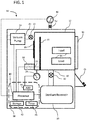
- FIG. 1 reflects a sterilization system 10, depicted schematically in block diagram-format. It comprises, a vacuum chamber 12 having a load (pack) 14 of instruments therein to be sterilized.
- the chamber 12 may be formed of any material that is sufficiently robust to handle pressures as low as approximately between 0.15 torr and 3 torr, and sufficiently inert to avoid reacting with or absorbing any sterilants introduced therein. Such materials may include aluminum and stainless steel.
- Chamber 12 may also include an openable and sealable barrier 16, such as a door, that may be opened to allow placement and removal of load 14 into chamber 12.
- the barrier should be sufficiently robust, and include a sufficiently robust seal, to withstand low pressures drawn within chamber 12 and avoid leaks between chamber 12 and the ambient environment.
- a vacuum pump 18 capable of reaching the desired operating pressure evacuates air and other gases, such as water vapor, from chamber 12.
- Vacuum pump 18 may include a hose or pipe 20 to connect it to chamber 12.
- Vacuum pump 18 may also include a valve 22, which may be opened or closed to assist or prevent pressure changes in chamber 12. For example, when the valve is open and the vacuum pump is operational, the pressure in chamber 12 may be lowered. Alternatively, when the valve is open and the vacuum pump is not operational, the pressure in the chamber may be equalized to the ambient pressure.
- a venting valve may be used to vent or evacuate chamber 12 to introduce ambient air into chamber 12 and return the pressure within chamber 12 to the ambient pressure. This venting valve, which is not shown in FIG.
- a hose or pipe may connect chamber 12 to the ambient environment and the venting valve may be disposed within this hose or pipe between the ambient environment and chamber 12.
- a pressure monitor 24 monitors the pressure in chamber 12. Particularly suitable pressure monitors are capacitance manometers available from MKS Instruments.
- a heating element 26 may be used to heat the chamber 12. It may comprise separate elements bonded to the outside of the chamber 12 in locations sufficient to uniformly heat the chamber 12.
- tank 28 may further include a valve 32, which may be disposed between chamber 12 and tank 28 to control the flow of sterilant from tank 28 through hose 30 and into chamber 12.
- a seal may be disposed between tank 28 and hose or pipe 30. The seal may be opened, e.g., by puncturing, to permit the sterilant enter hose or pipe 30. Accordingly, the seal may be fabricated from, among other things, a sheet of metal or plastic, such as aluminum foil.
- another hose or pipe with a valve positioned therein may be disposed between tank 28 and the ambient environment to further aid in venting chamber 12 after sterilant has been introduced therein.
- a power source and/or signal generator 33 and an electrode 34 disposed within chamber 12 may be provided to create an electric field within chamber 12 between electrode 34 and the interior surface of chamber 12 to create a plasma therein.
- a signal such as an RF signal, may be provided to electrode 34 from generator 33 by way of a feed through 35, such as a wire-type feed through. Creation of a plasma is useful for low temperature sterilization processes that use hydrogen peroxide gas. In these processes, the hydrogen peroxide gas may be excited to form a hydrogen peroxide plasma. Alternatively, another gas may be used to form the plasma, such as air, which may help lower hydrogen peroxide residuals upon the load to facilitate removal of hydrogen peroxide from chamber 12.
- Sterilization system 10 may also include a user interface 36, that may include output devices, such as a printer or display, and user-input devices, such as a keypad or touch screen.
- Sterilization system 10 may also include a humidity or relative humidity sensor 50, such as the HIH-4602-A/C Series Relative Humidity sensor produced by Honeywell International, Inc.
- a valve 52 is disposed between humidity sensor 50 and vacuum chamber 12 to shield sensor 50 from high concentrations of hydrogen peroxide, which could damage sensor 50. That is, valve 52 may be in an open state when hydrogen peroxide is not within chamber 12, thereby allowing sensor 50 to acquire humidity measurements of the air and/or gases within chamber 12.
- Valve 52 may be in a closed state when hydrogen peroxide is within chamber 12 and/or before hydrogen peroxide is introduced into chamber 12 from sterilant reservoir 28. When valve 52 is in a closed state, sensor 50 is sealed off from chamber 12 and any hydrogen peroxide therein, thereby protecting sensor 50 from being damaged by hydrogen peroxide.
- a control system 38 such as a digital computer, controls the operation of the system 10 and its various components.
- Control system 38 may employ one or more microprocessors 40. It may also employ a non-transitory storage medium 42, such as random access memory (RAM), a hard-disk drive, or flash memory, which can store data, such as pressure values, humidity values, and time values.
- An analog to digital (A2D) converter 44 may be used to convert analog data to digital data if analog data, such as pressure data and/or humidity data, is collected.
- a timer or clock circuit 45 keeps time.
- Control system 38 may further include software and/or logic by which the microprocessor may determine maximum or minimum values from among the pressure data and/or humidity data.
- Control system 38 may further include software and/or logic by which the microprocessor may compare pressure and/or relative humidity values to other pressure and/or relative humidity values.
- the control system is capable of storing pressure data P i and humidity data, H i which are acquired at various time increments i.
- the amount of time between neighboring time increments, designated ⁇ t may be equal to approximately 0.1 second, approximately 1 second, approximately 2 seconds, approximately 5 seconds, or approximately 10 seconds.
- the pressure data and relative humidity data may be measured throughout the sterilization process and stored in storage medium 42. The data may be collected as voltage outputs from the corresponding pressure or relative humidity sensor.
- load 14 is introduced into chamber 12 completely dry, i.e., without any moisture thereon.
- residual water may be introduced into the vacuum chamber.
- water may be in chamber 12 when the vacuum draw of the sterilization process commences, i.e., when vacuum pump 18 is activated.
- As the pressure in the chamber decreases at least a partial volume of the residual water may change phase to gas, which may interfere with a sterilization process, such as a hydrogen peroxide sterilization process.
- at least a partial volume of any residual water that does to change phase to gas may change phase to ice. Hydrogen peroxide may condense on this ice and prevent hydrogen peroxide from contacting the device underneath the ice, thereby further decreasing the efficacy of the sterilization process.
- the inventors have discovered a surprising mechanism by which a humidity or relative humidity sensor may be used to measure moisture content within a vacuum chamber such that the measurements may form a basis for determining whether hydrogen peroxide should be introduced into the chamber for the purpose of sterilization.
- Set forth herein is a new, useful, and inventive application of this discovery, which improves sterilization processes and load-conditioning techniques known in the art.
- the starting pressure in chamber 12 is equal to or approximately equal to the ambient pressure, e.g., atmospheric pressure.
- Chamber 12 may be sealed by closing barrier 16.
- Humidity or relative humidity sensor 50 is used to take a baseline reading of the humidity within chamber 12. Then, air may be withdrawn from chamber 12 by opening valve 22 of vacuum pump 18 and activating the pump to lower the pressure in chamber 12 to a conditioning pressure, P c , of between approximately 5 to approximately 15 torr, approximately 8 torr to approximately 12 torr, or approximately 10 torr.
- Valve 22 may then be closed and pump 18 deactivated in order to maintain the pressure within chamber 12 at Poor approximately P c for a period of time to allow residual water in load 14 to vaporize.
- Vaporization may be assisted by activating heating elements 26.
- the period of time, or dwell time, t d , during which valve 22 is closed to maintain pressure may be between approximately 1 second to approximately 5 minutes, approximately 1 second to approximately 1 minute, approximately 1 second to approximately 50 seconds, approximately 1 second to approximately 10 seconds, or approximately 5 seconds.
- Time may be monitored by timer 45 and each time increment ⁇ t corresponding to each humidity measurement stored in non-transitory storage medium 42.
- humidity or relative humidity sensor 50 measures the humidity at each time increment ⁇ t, and the output of sensor 50, typically a voltage output, is also recorded in nontransitory storage medium 42.
- chamber 12 is pressurized.
- valve 22 and/or the venting valve may be opened to allow ambient air into chamber 12.
- air enters or rushes into chamber 12 air and water vapor in the chamber mix and, as the inventors discovered, this activity brings water molecules within chamber 12 into contact with the humidity sensor. If any residual water was introduced into vacuum chamber 12 when load 14 was disposed therein, introduction of air having the same moisture content as the air that was drawn out of chamber 12 causes the overall moisture content within chamber 12 to be greater than what it was originally. That is, the moisture content within chamber 12 should be higher than the baseline moisture content as determined by humidity sensor 50.
- the process begins with ambient air in chamber 12. Hospital personnel dispose load 14 therein, but with a volume of residual water within the load because the load was not sufficiently dried.
- the pressure in chamber 12 is lowered to a conditioning pressure of approximately 10 torr, valve 22 is then closed, and the pressure maintained at approximately at the conditioning pressure for a dwell time of approximately 0.1 seconds, 1 second, 5 seconds, or 10 seconds. From approximately the time at which the pressure in chamber 12 started being lowered, at least some of the molecules of the residual water vaporize. Valve 22 or the venting valve is then opened to pressurize and/or vent chamber 12.
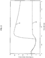
- Humidity data from one experiment are reflected in the graph of FIG. 2 .
- the sterilization system used for this experiment was a 100NX® modified to include a humidity sensor capable or measuring humidity within the vacuum chamber.
- An isolation valve was placed between the humidity sensor and the vacuum chamber that could be closed to protect the sensor from any hydrogen peroxide that may be introduced into the vacuum chamber.
- the graph plots voltage output from the humidity sensor versus time.
- This experiment included two runs. In one run, a wet load containing approximately 5 ml of residual water was disposed in the vacuum chamber. In another run, a dry load was disposed in the vacuum chamber.
- Reference numeral 62 corresponds to the plot of humidity data for the wet load.
- Reference numeral 60 corresponds to the plot of humidity data for the dry load.
- the humidity sensor output a voltage of approximately 1.6 volts for the wet load and approximately 1.5 volts for the dry load.
- the vacuum pump of the modified 100NX® began to purge air from the chamber.
- Humidity data such as the data reflected in FIG. 2 , may thus be used as a basis for determining whether a load is sufficiently dry for hydrogen peroxide sterilization.
- humidity values on a plot of humidity vs. time corresponding to times subsequent to venting which may include the maximum humidity value on the plot, may be compared to the baseline value of humidity for a dry load, i.e., the humidity of an empty chamber or a chamber with a dry load disposed therein that was previously determined when the chamber was at ambient conditions.
- these humidity values may be compared to the minimum value of humidity on the humidity vs.
- a maximum humidity value greater than the baseline humidity value is considered to indicate a wet load whereas a maximum humidity value equal to or less than the baseline humidity value is considered to indicate a dry load.
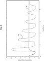
- Reference numeral 64 corresponds to a dry load.
- Reference numeral 66 corresponds to a load with approximately 1 mL of residual water disposed thereon.
- Reference numeral 68 corresponds to a load with approximately 2 mL of residual water disposed thereon.
- Reference numeral 70 corresponds to a load with approximately 3 mL of residual water disposed thereon.
- Reference numeral 72 corresponds to a load with approximately 4 mL of residual water disposed thereon.
- Reference numeral 74 corresponds to a load with approximately 5 mL of residual water disposed thereon.
- Reference numeral 76 corresponds to a load with approximately 10 mL of residual water disposed thereon.
- the humidity values for each sample begin overlapping or approximately overlapping. That is, the humidity values for each sample, from the dry sample to the wettest 10 ml sample, are equal or approximately equal.
- the chamber is sealed, at which point the humidity output for each sample is approximately 1.1 volts, the minimum humidity value for each curve.
- An increase in the humidity values is immediately thereafter observed on the 10 ml curve (reference numeral 76).
- the humidity vs. time curves have each diverged from the others.
- the maximum humidity value is approximately 3.7 volts.
- the maximum humidity value is approximately 3.6 volts.
- the maximum humidity value is approximately 3.4 volts.
- the maximum humidity value is approximately 3.2 volts.
- the maximum humidity value is approximately 2.8 volts.
- the maximum humidity value is approximately 2.2 volts.
- the humidity values reach approximately 1.4 volts, which is less than the baseline humidity value.
- the maximum humidity value of a load is approximately 3.5 volts, it may be determined that the load included approximately 4 ml to 5 ml of residual water.
- the data suggest that if the maximum humidity value is approximately 0.5 volts to 0.75 volts greater than the baseline humidity value, or approximately 1.0 volts to 1.25 volts greater than the minimum humidity value, the load may be too wet to sterilize reliably with hydrogen peroxide. Accordingly, these data may be used as a basis for determining that hydrogen peroxide should not be introduced into the vacuum chamber until after the load has been dried, either manually or via a load conditioning process.
- the load may be sufficiently dry for sterilization by hydrogen peroxide. Accordingly, these data may be used as basis for determining that hydrogen peroxide may be introduced into the vacuum chamber for sterilization.
- Vacuum pulsing typically begins when a vacuum chamber is in a low pressure state and includes some combination of providing energy to a load in the chamber, pressurizing the chamber, and reducing the pressure.
- air may be withdrawn from a vacuum chamber containing a wet load having, e.g., 5 ml of water therein until the pressure within the chamber reaches a conditioning pressure, P c , of approximately 10 torr. Following a dwell time during which the conditioning pressure is maintained, the chamber may be vented.
- the venting should cause the humidity sensor to output a maximum humidity value of approximately 3.6 volts, based on the foregoing description concerning FIGs. 2-3 .
- energy may be provided to the load by way of a plasma or by using heating elements, such as heating elements 26 to further exacerbate vaporization of any residual water.
- the chamber may be vented to introduce ambient air into the chamber that is warmer than the air presently in the chamber, which may warm the load and residual water thereon.
- ambient air there should be less than 5 ml of residual water disposed within the load because at least some of the residual water should have been vaporized during the foregoing steps, which is what causes the maximum humidity value to be greater than the baseline humidity value.
- some residual water may remain.
- air may be withdrawn from the chamber, and perhaps energized, before the chamber is vented again.
- Output from the humidity sensor should indicate that some water remained, but that the amount of water that remained is less than the original 5 ml.
- FIG. 4 Data from a vacuum pulsing process is reflected in FIG. 4 .
- a plot of data corresponding to humidity vs. time for a wet load containing 5 ml of water that is subject to vacuum pulsing is indicated by reference numeral 82.
- a plot of data corresponding to humidity vs. time for a dry load is indicated by reference numeral 80.
- the load conditioning process for the wet load begins in a manner similar to the process described in conjunction with FIG. 2 .
- the first maximum humidity value is approximately equal to 3.4 volts, close to the corresponding value of approximately 3.6 volts in FIG. 2 .
- Air is then repeatedly withdrawn to a conditioning pressure, P c , which may be approximately equal to 10 torr, and subsequently reintroduced into the chamber by venting the chamber, thereby energizing any water that remains therein.
- P c a conditioning pressure
- the maximum humidity value is compared to the baseline humidity value to determine if the load was dry. If it is not dry, the vacuum pulsing continues until the maximum humidity value is less than or equal to the baseline value.
- the sample load having 5 ml of residual water therein was determined to be successfully dried via load conditioning following six venting steps.
- a low-temperature chemical sterilization system such as sterilization system 10, may be designed to perform various routines concerning determining whether any water is in vacuum chamber 12, whether load conditioning should be performed, and whether hydrogen peroxide should be introduced into the vacuum chamber.
- An example sterilization process which includes steps that a sterilization system may perform, such as a routine for determining whether load conditioning should be performed, a load conditioning routine, and a sterilization routine, as well as other steps that a healthcare worker may perform, is set forth in Fig. 5 . This process is set forth only as an example to further illustrate the disclosed subject matter and explain its utility. Many of the steps included in this process may be performed alternatively or additionally before or after other steps. The steps set forth in this example may be performed in varying combinations and permutations without departing from the scope of the disclosed subject matter. For example, load conditioning routines may be performed and/or air plasma introduced into the vacuum chamber before any sterilant is introduced into the vacuum chamber.
- the example sterilization process begins with health care personnel cleaning non-sterile instruments soiled from prior use using water, washing solution, or a water-soluble instrument lubricant.
- the instruments are then dried using any or a combination of various techniques known in the art, such as heating the instruments or blowing compressed air into the instruments, particularly lumens of the instrument.
- the dried instruments may be placed within a sterilization box or rack made from, e.g., a metal, such as aluminum, or a plastic, such as polycarbonate.
- the instruments and/or rack are wrapped within a sterilization wrap to form sterilization pack or load 14.
- the wrap acts as a barrier to microorganisms, but it permits passage of a sterilant therethrough.
- a biological indicator may also be disposed within the chamber.
- the chamber is closed and sealed by closing barrier 16.
- timer 45 is started and control system 38 begins recording humidity data output from humidity sensor 50 at each time increment ⁇ t, which may be every approximately 0.1 seconds or approximately 1 second.
- the first humidity data point recorded, which corresponds to time t 0 and the original pressure in the chamber, which may be equivalent to the ambient pressure, is the baseline humidity value, H b .
- Valve 22 of vacuum pump 18 is opened and vacuum pump 18 is activated. Air is withdrawn from chamber 12 by pump 18 until pressure sensor 24 indicates that the pressure in chamber 12 is less than or equal to a predetermined conditioning pressure, P c .
- P c may be any pressure at which water becomes readily vaporized, for example, approximately 10 torr.
- pump 18 is deactivated and valve 22 is closed.
- the pressure in chamber 12 is maintained at P c for a period of time, or dwell time, t d , which may be equal to approximately 0.1 seconds, approximately 0.5 seconds, approximately 1 second, approximately 5 seconds or approximately 10 seconds.
- t d dwell time
- chamber 12 is vented to atmosphere, perhaps by opening valve 22 without activating pump 18 and/or opening the venting valve.
- Control system 38 and particularly processor 40 check subsequent values of H i to determine whether any such values are greater than the baseline humidity value, H b .
- processor 40 compares only the maximum value of H i , i.e., H max , to H b . In other versions of the process, processor 40 compares H i and/or H max to the minimum value of H i , i.e., H min . If no H i is greater than H b , and/or if H max is less than H b , then it may be presumed that load 14 is dry. Accordingly, the sterilization cycle of the sterilization process may commence. Specifically, valve 22 is opened and pump 18 activated to withdraw more air from chamber 12 until a predetermined sterilization pressure, P s , is achieved in chamber 12.
- P s sterilization pressure
- P s may be approximately 0.3 torr, approximately 0.5 torr, approximately 1 torr, approximately 2 torr, or approximately 3 torr.
- a load conditioning cycle may begin.
- vacuum pulsing is performed by repeating the steps of withdrawing air from the chamber until the pressure has reached P c , maintaining the pressure at P c for t d , venting the chamber, and comparing subsequent H i to H b .
- load 14 is dry. If this is not the case, then another round of load conditioning may be performed.
- Load conditioning may be repeated as many times as necessary to dry the load. Alternatively, the process may time out and abort if the load is not sufficiently dried within a certain number of conditioning attempts, such as 2, 5, 7, or 10 attempts.
Landscapes
- Health & Medical Sciences (AREA)
- Life Sciences & Earth Sciences (AREA)
- General Health & Medical Sciences (AREA)
- Epidemiology (AREA)
- Veterinary Medicine (AREA)
- Public Health (AREA)
- Animal Behavior & Ethology (AREA)
- Chemical & Material Sciences (AREA)
- General Chemical & Material Sciences (AREA)
- Chemical Kinetics & Catalysis (AREA)
- Medicinal Chemistry (AREA)
- Immunology (AREA)
- Pathology (AREA)
- General Physics & Mathematics (AREA)
- Biochemistry (AREA)
- Analytical Chemistry (AREA)
- Physics & Mathematics (AREA)
- Food Science & Technology (AREA)
- Engineering & Computer Science (AREA)
- Apparatus For Disinfection Or Sterilisation (AREA)
Applications Claiming Priority (1)
| Application Number | Priority Date | Filing Date | Title |
|---|---|---|---|
| US15/151,774 US9931427B2 (en) | 2016-05-11 | 2016-05-11 | Apparatus and method for detecting moisture in a vacuum chamber |
Publications (3)
| Publication Number | Publication Date |
|---|---|
| EP3243531A2 true EP3243531A2 (de) | 2017-11-15 |
| EP3243531A3 EP3243531A3 (de) | 2018-02-28 |
| EP3243531B1 EP3243531B1 (de) | 2023-10-04 |
Family
ID=58738886
Family Applications (1)
| Application Number | Title | Priority Date | Filing Date |
|---|---|---|---|
| EP17170503.1A Active EP3243531B1 (de) | 2016-05-11 | 2017-05-10 | Vorrichtung und verfahren zum nachweis von feuchtigkeit in einer vakuumkammer |
Country Status (12)
| Country | Link |
|---|---|
| US (2) | US9931427B2 (de) |
| EP (1) | EP3243531B1 (de) |
| JP (2) | JP6991736B2 (de) |
| KR (1) | KR20170127364A (de) |
| CN (1) | CN107432943B (de) |
| AU (1) | AU2017203004A1 (de) |
| BR (1) | BR102017009796A2 (de) |
| CA (1) | CA2966081A1 (de) |
| ES (1) | ES2959619T3 (de) |
| MX (1) | MX2017006074A (de) |
| RU (1) | RU2017116166A (de) |
| TW (1) | TW201807396A (de) |
Cited By (1)
| Publication number | Priority date | Publication date | Assignee | Title |
|---|---|---|---|---|
| CN111388728A (zh) * | 2020-05-08 | 2020-07-10 | 中国人民解放军海军第九七一医院 | 一种传染病防控用消毒装置 |
Families Citing this family (5)
| Publication number | Priority date | Publication date | Assignee | Title |
|---|---|---|---|---|
| US10441672B2 (en) | 2016-04-26 | 2019-10-15 | Asp Global Manufacturing Gmbh | Apparatus and method for detecting moisture in a vacuum chamber |
| US10458705B2 (en) | 2017-02-02 | 2019-10-29 | Asp Global Manufacturing Gmbh | Apparatus and method for detecting moisture in a vacuum chamber |
| CN109856327B (zh) * | 2019-01-16 | 2023-11-28 | 徐立杰 | 一种通过湿度测量确定被测物质含水量的装置和方法 |
| CN111498354B (zh) * | 2020-04-28 | 2023-05-05 | 安徽华信电动科技股份有限公司 | 一种基于产品配置的垃圾车装填装置 |
| US11603551B2 (en) | 2020-12-02 | 2023-03-14 | Steritec Products Mfg. Co., Inc. | Biological indicators, and systems and methods for determining efficacy of sterilization |
Family Cites Families (19)
| Publication number | Priority date | Publication date | Assignee | Title |
|---|---|---|---|---|
| DE3146349C2 (de) | 1981-11-23 | 1983-12-15 | Georg Wagner KG, 8000 München | Sterilisierbehälter |
| US4756882A (en) | 1985-06-21 | 1988-07-12 | Surgikos Inc. | Hydrogen peroxide plasma sterilization system |
| US4643876A (en) | 1985-06-21 | 1987-02-17 | Surgikos, Inc. | Hydrogen peroxide plasma sterilization system |
| US5445792A (en) * | 1992-03-13 | 1995-08-29 | American Sterilizer Company | Optimum hydrogen peroxide vapor sterlization method |
| US5317896A (en) | 1992-03-13 | 1994-06-07 | American Sterilizer Company | Method of detecting liquid in a sterilization system |
| US5872359A (en) * | 1995-07-27 | 1999-02-16 | American Sterilizer Company | Real-time monitor and control system and method for hydrogen peroxide vapor decontamination |
| US5641455A (en) | 1995-12-22 | 1997-06-24 | Minnesota Mining & Manufacturing Company | Sterilizer with gas control |
| US5788925A (en) | 1996-02-16 | 1998-08-04 | Steris Corporation | Method for real time monitoring and control of load sterilization and parametric release |
| US5961922A (en) * | 1996-10-04 | 1999-10-05 | Johnson & Johnson Medical, Inc. | Method and apparatus for detecting water entrapment in a vaccum chamber |
| US20110176959A1 (en) * | 2004-11-26 | 2011-07-21 | Human Meditek Co., Ltd. | Hydrogen peroxide vapor sterilizer and sterilizing methods using the same |
| CN101065155A (zh) * | 2004-11-26 | 2007-10-31 | 互曼迈迪泰克公司 | 过氧化氢蒸汽灭菌装置及使用该装置的灭菌方法 |
| US8109871B2 (en) | 2005-05-06 | 2012-02-07 | Minntech Corporation | Endoscope integrity tester including context-sensitive compensation and methods of context-sensitive integrity testing |
| GB2428578B (en) | 2005-07-28 | 2010-06-09 | Bioquell | Determining bacterial kill by vaporised sterilants |
| NL2000064C2 (nl) | 2006-04-28 | 2007-10-30 | Infection Control B V | Werkwijze en inrichting voor het desinfecteren van een ruimte. |
| US7919059B2 (en) * | 2007-04-27 | 2011-04-05 | American Sterilizer Company | Vaporized hydrogen peroxide decontamination system with concentration adjustment mode |
| US8366995B2 (en) | 2009-06-11 | 2013-02-05 | Sterilucent, Inc. | Apparatus and method for drying and then sterilizing objects in a load using a chemical sterilant |
| CN102423495B (zh) * | 2011-11-24 | 2014-10-01 | 何德贤 | 一种脉动蒸汽灭菌工艺及其蒸汽灭菌器 |
| EP2902042A4 (de) | 2012-09-27 | 2016-09-21 | Saraya Co Ltd | Sterilisationsverfahren und vorrichtung |
| US10441672B2 (en) * | 2016-04-26 | 2019-10-15 | Asp Global Manufacturing Gmbh | Apparatus and method for detecting moisture in a vacuum chamber |
-
2016
- 2016-05-11 US US15/151,774 patent/US9931427B2/en active Active
-
2017
- 2017-05-03 CA CA2966081A patent/CA2966081A1/en not_active Abandoned
- 2017-05-05 AU AU2017203004A patent/AU2017203004A1/en not_active Abandoned
- 2017-05-08 KR KR1020170057231A patent/KR20170127364A/ko unknown
- 2017-05-09 TW TW106115234A patent/TW201807396A/zh unknown
- 2017-05-09 MX MX2017006074A patent/MX2017006074A/es unknown
- 2017-05-10 JP JP2017093690A patent/JP6991736B2/ja active Active
- 2017-05-10 ES ES17170503T patent/ES2959619T3/es active Active
- 2017-05-10 RU RU2017116166A patent/RU2017116166A/ru not_active Application Discontinuation
- 2017-05-10 BR BR102017009796-0A patent/BR102017009796A2/pt not_active Application Discontinuation
- 2017-05-10 EP EP17170503.1A patent/EP3243531B1/de active Active
- 2017-05-11 CN CN201710332848.8A patent/CN107432943B/zh active Active
-
2018
- 2018-03-07 US US15/914,793 patent/US10799609B2/en active Active
-
2021
- 2021-12-07 JP JP2021198414A patent/JP7391929B2/ja active Active
Non-Patent Citations (1)
| Title |
|---|
| None |
Cited By (1)
| Publication number | Priority date | Publication date | Assignee | Title |
|---|---|---|---|---|
| CN111388728A (zh) * | 2020-05-08 | 2020-07-10 | 中国人民解放军海军第九七一医院 | 一种传染病防控用消毒装置 |
Also Published As
| Publication number | Publication date |
|---|---|
| CN107432943A (zh) | 2017-12-05 |
| AU2017203004A1 (en) | 2017-11-30 |
| JP2017205506A (ja) | 2017-11-24 |
| US9931427B2 (en) | 2018-04-03 |
| US20170326265A1 (en) | 2017-11-16 |
| CA2966081A1 (en) | 2017-11-11 |
| TW201807396A (zh) | 2018-03-01 |
| ES2959619T3 (es) | 2024-02-27 |
| EP3243531A3 (de) | 2018-02-28 |
| EP3243531B1 (de) | 2023-10-04 |
| RU2017116166A (ru) | 2018-11-13 |
| BR102017009796A2 (pt) | 2017-11-28 |
| KR20170127364A (ko) | 2017-11-21 |
| JP2022022335A (ja) | 2022-02-03 |
| US10799609B2 (en) | 2020-10-13 |
| CN107432943B (zh) | 2022-05-27 |
| US20180193513A1 (en) | 2018-07-12 |
| MX2017006074A (es) | 2018-08-22 |
| JP7391929B2 (ja) | 2023-12-05 |
| JP6991736B2 (ja) | 2022-02-03 |
Similar Documents
| Publication | Publication Date | Title |
|---|---|---|
| US10799609B2 (en) | Apparatus and method for detecting moisture in a vacuum chamber | |
| US11020505B2 (en) | Apparatus and method for detecting moisture in a vacuum chamber | |
| US20240003624A1 (en) | Apparatus And Method For Detecting Moisture In A Vacuum Chamber | |
| KR100506687B1 (ko) | 진공챔버속에들어있는물의검출방법및검출장치 | |
| EP3570898B1 (de) | Verfahren zum nachweis und flüssigkeiten und trocknen | |
| CN113613685A (zh) | 用于灭菌装置的负载体积确定方法 | |
| BR102018001672A2 (pt) | Aparelho e método para a detecção de umidade em uma câmara de vácuo |
Legal Events
| Date | Code | Title | Description |
|---|---|---|---|
| PUAI | Public reference made under article 153(3) epc to a published international application that has entered the european phase |
Free format text: ORIGINAL CODE: 0009012 |
|
| STAA | Information on the status of an ep patent application or granted ep patent |
Free format text: STATUS: THE APPLICATION HAS BEEN PUBLISHED |
|
| AK | Designated contracting states |
Kind code of ref document: A2 Designated state(s): AL AT BE BG CH CY CZ DE DK EE ES FI FR GB GR HR HU IE IS IT LI LT LU LV MC MK MT NL NO PL PT RO RS SE SI SK SM TR |
|
| AX | Request for extension of the european patent |
Extension state: BA ME |
|
| PUAL | Search report despatched |
Free format text: ORIGINAL CODE: 0009013 |
|
| AK | Designated contracting states |
Kind code of ref document: A3 Designated state(s): AL AT BE BG CH CY CZ DE DK EE ES FI FR GB GR HR HU IE IS IT LI LT LU LV MC MK MT NL NO PL PT RO RS SE SI SK SM TR |
|
| AX | Request for extension of the european patent |
Extension state: BA ME |
|
| RIC1 | Information provided on ipc code assigned before grant |
Ipc: A61L 2/24 20060101ALI20180122BHEP Ipc: A61L 2/20 20060101AFI20180122BHEP |
|
| STAA | Information on the status of an ep patent application or granted ep patent |
Free format text: STATUS: REQUEST FOR EXAMINATION WAS MADE |
|
| 17P | Request for examination filed |
Effective date: 20180823 |
|
| RBV | Designated contracting states (corrected) |
Designated state(s): AL AT BE BG CH CY CZ DE DK EE ES FI FR GB GR HR HU IE IS IT LI LT LU LV MC MK MT NL NO PL PT RO RS SE SI SK SM TR |
|
| RAP1 | Party data changed (applicant data changed or rights of an application transferred) |
Owner name: ASP GLOBAL MANUFACTURING GMBH |
|
| STAA | Information on the status of an ep patent application or granted ep patent |
Free format text: STATUS: EXAMINATION IS IN PROGRESS |
|
| STAA | Information on the status of an ep patent application or granted ep patent |
Free format text: STATUS: EXAMINATION IS IN PROGRESS |
|
| 17Q | First examination report despatched |
Effective date: 20211207 |
|
| GRAP | Despatch of communication of intention to grant a patent |
Free format text: ORIGINAL CODE: EPIDOSNIGR1 |
|
| STAA | Information on the status of an ep patent application or granted ep patent |
Free format text: STATUS: GRANT OF PATENT IS INTENDED |
|
| INTG | Intention to grant announced |
Effective date: 20230419 |
|
| GRAS | Grant fee paid |
Free format text: ORIGINAL CODE: EPIDOSNIGR3 |
|
| GRAA | (expected) grant |
Free format text: ORIGINAL CODE: 0009210 |
|
| STAA | Information on the status of an ep patent application or granted ep patent |
Free format text: STATUS: THE PATENT HAS BEEN GRANTED |
|
| AK | Designated contracting states |
Kind code of ref document: B1 Designated state(s): AL AT BE BG CH CY CZ DE DK EE ES FI FR GB GR HR HU IE IS IT LI LT LU LV MC MK MT NL NO PL PT RO RS SE SI SK SM TR |
|
| REG | Reference to a national code |
Ref country code: GB Ref legal event code: FG4D |
|
| REG | Reference to a national code |
Ref country code: CH Ref legal event code: EP |
|
| REG | Reference to a national code |
Ref country code: IE Ref legal event code: FG4D |
|
| REG | Reference to a national code |
Ref country code: DE Ref legal event code: R096 Ref document number: 602017074841 Country of ref document: DE |
|
| P01 | Opt-out of the competence of the unified patent court (upc) registered |
Effective date: 20231109 |
|
| REG | Reference to a national code |
Ref country code: LT Ref legal event code: MG9D |
|
| REG | Reference to a national code |
Ref country code: NL Ref legal event code: MP Effective date: 20231004 |
|
| REG | Reference to a national code |
Ref country code: ES Ref legal event code: FG2A Ref document number: 2959619 Country of ref document: ES Kind code of ref document: T3 Effective date: 20240227 |
|
| REG | Reference to a national code |
Ref country code: AT Ref legal event code: MK05 Ref document number: 1617053 Country of ref document: AT Kind code of ref document: T Effective date: 20231004 |
|
| PG25 | Lapsed in a contracting state [announced via postgrant information from national office to epo] |
Ref country code: NL Free format text: LAPSE BECAUSE OF FAILURE TO SUBMIT A TRANSLATION OF THE DESCRIPTION OR TO PAY THE FEE WITHIN THE PRESCRIBED TIME-LIMIT Effective date: 20231004 |
|
| PG25 | Lapsed in a contracting state [announced via postgrant information from national office to epo] |
Ref country code: GR Free format text: LAPSE BECAUSE OF FAILURE TO SUBMIT A TRANSLATION OF THE DESCRIPTION OR TO PAY THE FEE WITHIN THE PRESCRIBED TIME-LIMIT Effective date: 20240105 |
|
| PG25 | Lapsed in a contracting state [announced via postgrant information from national office to epo] |
Ref country code: IS Free format text: LAPSE BECAUSE OF FAILURE TO SUBMIT A TRANSLATION OF THE DESCRIPTION OR TO PAY THE FEE WITHIN THE PRESCRIBED TIME-LIMIT Effective date: 20240204 |
|
| PG25 | Lapsed in a contracting state [announced via postgrant information from national office to epo] |
Ref country code: LT Free format text: LAPSE BECAUSE OF FAILURE TO SUBMIT A TRANSLATION OF THE DESCRIPTION OR TO PAY THE FEE WITHIN THE PRESCRIBED TIME-LIMIT Effective date: 20231004 |
|
| PG25 | Lapsed in a contracting state [announced via postgrant information from national office to epo] |
Ref country code: AT Free format text: LAPSE BECAUSE OF FAILURE TO SUBMIT A TRANSLATION OF THE DESCRIPTION OR TO PAY THE FEE WITHIN THE PRESCRIBED TIME-LIMIT Effective date: 20231004 |
|
| PG25 | Lapsed in a contracting state [announced via postgrant information from national office to epo] |
Ref country code: LT Free format text: LAPSE BECAUSE OF FAILURE TO SUBMIT A TRANSLATION OF THE DESCRIPTION OR TO PAY THE FEE WITHIN THE PRESCRIBED TIME-LIMIT Effective date: 20231004 Ref country code: IS Free format text: LAPSE BECAUSE OF FAILURE TO SUBMIT A TRANSLATION OF THE DESCRIPTION OR TO PAY THE FEE WITHIN THE PRESCRIBED TIME-LIMIT Effective date: 20240204 Ref country code: GR Free format text: LAPSE BECAUSE OF FAILURE TO SUBMIT A TRANSLATION OF THE DESCRIPTION OR TO PAY THE FEE WITHIN THE PRESCRIBED TIME-LIMIT Effective date: 20240105 Ref country code: BG Free format text: LAPSE BECAUSE OF FAILURE TO SUBMIT A TRANSLATION OF THE DESCRIPTION OR TO PAY THE FEE WITHIN THE PRESCRIBED TIME-LIMIT Effective date: 20240104 Ref country code: AT Free format text: LAPSE BECAUSE OF FAILURE TO SUBMIT A TRANSLATION OF THE DESCRIPTION OR TO PAY THE FEE WITHIN THE PRESCRIBED TIME-LIMIT Effective date: 20231004 Ref country code: PT Free format text: LAPSE BECAUSE OF FAILURE TO SUBMIT A TRANSLATION OF THE DESCRIPTION OR TO PAY THE FEE WITHIN THE PRESCRIBED TIME-LIMIT Effective date: 20240205 |