EP3243337B1 - Microphone with dustproof through holes - Google Patents
Microphone with dustproof through holes Download PDFInfo
- Publication number
- EP3243337B1 EP3243337B1 EP15876435.7A EP15876435A EP3243337B1 EP 3243337 B1 EP3243337 B1 EP 3243337B1 EP 15876435 A EP15876435 A EP 15876435A EP 3243337 B1 EP3243337 B1 EP 3243337B1
- Authority
- EP
- European Patent Office
- Prior art keywords
- backplate
- microphone
- hole
- holes
- diaphragm
- Prior art date
- Legal status (The legal status is an assumption and is not a legal conclusion. Google has not performed a legal analysis and makes no representation as to the accuracy of the status listed.)
- Active
Links
Images


Classifications
-
- H—ELECTRICITY
- H04—ELECTRIC COMMUNICATION TECHNIQUE
- H04R—LOUDSPEAKERS, MICROPHONES, GRAMOPHONE PICK-UPS OR LIKE ACOUSTIC ELECTROMECHANICAL TRANSDUCERS; DEAF-AID SETS; PUBLIC ADDRESS SYSTEMS
- H04R1/00—Details of transducers, loudspeakers or microphones
- H04R1/08—Mouthpieces; Microphones; Attachments therefor
- H04R1/083—Special constructions of mouthpieces
-
- H—ELECTRICITY
- H04—ELECTRIC COMMUNICATION TECHNIQUE
- H04R—LOUDSPEAKERS, MICROPHONES, GRAMOPHONE PICK-UPS OR LIKE ACOUSTIC ELECTROMECHANICAL TRANSDUCERS; DEAF-AID SETS; PUBLIC ADDRESS SYSTEMS
- H04R1/00—Details of transducers, loudspeakers or microphones
- H04R1/02—Casings; Cabinets ; Supports therefor; Mountings therein
-
- H—ELECTRICITY
- H04—ELECTRIC COMMUNICATION TECHNIQUE
- H04R—LOUDSPEAKERS, MICROPHONES, GRAMOPHONE PICK-UPS OR LIKE ACOUSTIC ELECTROMECHANICAL TRANSDUCERS; DEAF-AID SETS; PUBLIC ADDRESS SYSTEMS
- H04R19/00—Electrostatic transducers
- H04R19/005—Electrostatic transducers using semiconductor materials
-
- H—ELECTRICITY
- H04—ELECTRIC COMMUNICATION TECHNIQUE
- H04R—LOUDSPEAKERS, MICROPHONES, GRAMOPHONE PICK-UPS OR LIKE ACOUSTIC ELECTROMECHANICAL TRANSDUCERS; DEAF-AID SETS; PUBLIC ADDRESS SYSTEMS
- H04R19/00—Electrostatic transducers
- H04R19/04—Microphones
-
- H—ELECTRICITY
- H04—ELECTRIC COMMUNICATION TECHNIQUE
- H04R—LOUDSPEAKERS, MICROPHONES, GRAMOPHONE PICK-UPS OR LIKE ACOUSTIC ELECTROMECHANICAL TRANSDUCERS; DEAF-AID SETS; PUBLIC ADDRESS SYSTEMS
- H04R2201/00—Details of transducers, loudspeakers or microphones covered by H04R1/00 but not provided for in any of its subgroups
- H04R2201/003—Mems transducers or their use
Definitions
- a plurality of through holes may be formed in the backplate 5.
- the inventor of the present application discovers that if some larger through holes are formed in the backplate 5, the noise of the microphone would be decreased, thereby a higher signal to noise ratio (SNR) can be achieved.
- SNR signal to noise ratio
- external particles would easily be dropped, through the larger through holes, into the sound cavity formed between the backplate 5 and the diaphragm 3, therefore the performance of the microphone is affected.
Description
- The present invention relates generally to a microphone, more particularly, to a microphone with dustproof through holes.
-
U.S.Pat.No.7,912,236 , discloses a sound transducer structure having a perforated backplate with multiple circular through holes extending through the backplate. However, if the diameters of the circular through holes formed in the backplate are overlarge, alien particles would easily pass through those large circular holes and drop into the sound cavity of the sound transducer structure, which may form a leakage path, resulting in the microphone being disabled. -
US application publication No. 2011/0075866 A1 discloses a microphone with backplate having specially shaped through-holes. -
EP application publication No. 2530954 A2 discloses a plate, a transducer, a method for making a transducer, and a method for operating a transducer. - The present invention is directed to providing a microphone with better dustproof effect.
- A microphone provided according to embodiments of the present invention comprising:
- a silicon substrate;
- a diaphragm disposed over the silicon substrate;
- a backplate disposed over the diaphragm, the backplate having a plurality of through holes formed therein and a barrier structure;
- the plurality of through holes being arranged in a through hole pattern on the backplate ;
- the barrier structure having one or more protruding portions extending from at least one part of edges of the barrier structure, wherein the protruding portion of the barrier structure has a thickness smaller than the thickness of the backplate, thereby the section shape of at least one through hole being a shape with one or more inwardly concave portions.
- In an alternative embodiment, the section shape of the at least one through hole is an approximate Y-type shape with an inwardly concave portion, an approximate polygon with an inwardly concave portion, or an approximate circle with an inwardly concave portion.
- In an alternative embodiment, the silicon substrate is a substrate with a through hole therein.
- In an alternative embodiment, an insulation layer is disposed between the silicon substrate and the diaphragm.
- In an alternative embodiment, an insulation layer is disposed between the diaphragm and the backplate to form an air gap therebetween.
- In an alternative embodiment, the microphone is a stand-alone MEMS microphone or a CMOS integrated system-on-chip microphone.
- By arranging through holes with an irregular shape in the backplate, a backplate provided with a specific through hole pattern may be formed according to the embodiments of the present invention. Compared to an existing backplate with a conventional through hole pattern, the backplate provided by the invention can prevent the larger particles from dropping into the microphone through the through holes, thus resulting in good dustproof effect.
- For a more complete understanding of the present invention, and the advantages thereof, reference is now made to the following descriptions taken in conjunction with the accompanying drawings, in which:
-
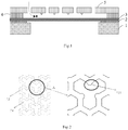
Fig.1 illustrates a structural schematic diagram of a MEMS microphone according to one embodiment of the invention. -
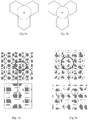
Fig. 2 illustrates a diagram representing a backplate through hole pattern according to one embodiment of the invention. -
Figs.3a and 3b show the section shapes contrasting an existing Y-type through hole with a Y-type through hole according to one embodiment of the invention. -
Figs.4a and 4b illustrate the contrast of an existing backplate through hole pattern and a backplate through hole pattern according to one embodiment of the present invention. -
Figs.5a to 5d show the section shapes contrasting an existing backplate through hole with the backplate through holes according to the embodiments of the invention. -
Fig.6 shows the section shapes contrasting an existing backplate through hole with the backplate through holes according to the embodiments of the invention. -
Fig.7a is a diagram of a backplate through hole pattern according to one embodiment of the prevent invention. -
Fig.7b is a cross-section view of the backplate through hole pattern along the A-A line shown inFig. 7a . - Corresponding numerals and symbols in the different figures generally refer to corresponding parts unless otherwise indicated. The figures are drawn to clearly illustrate the relevant aspects of the embodiments and are not necessarily drawn to scale.
- The making and using of some embodiments are discussed in detail below. It should be appreciated, however, that the present disclosure provides many applicable inventive concepts that can be embodied in a wide variety of specific contexts. The specific embodiments discussed are merely illustrative of specific ways to make and use the disclosure, and do not limit the scope of the disclosure.
- It is understood that the following disclosure provides many different embodiments, or examples, for implementing different features. Specific examples of components and arrangements are described below to simplify the present disclosure. These are of course, merely examples and are not intended to be limiting. In addition, the present disclosure may repeat reference numerals and/or letters in the various examples. This repetition is for the purpose of simplicity and clarity and does not in itself dictate a relationship between the various embodiments and/or configurations discussed. Moreover, the formation of a first feature over a second feature in the description that follows may include embodiments in which the first and second features are formed in direct contact, and may also include embodiments in which additional features may be formed interposing the first and second features, such that the first and second features may not be in direct contact.
-
Fig. 1 illustrates a structural schematic diagram of a MEMS microphone according to one embodiment of the invention. As shown inFig. 1 , a through backhole may be formed in asilicon substrate 1, and an insulation layer 2 may be disposed on thesilicon substrate 1. Adiaphragm 3 may be disposed on the insulation layer 2 and anotherinsulation layer 4 may be disposed on thediaphragm 3. Abackplate 5 may be disposed on theinsulation layer 4 and suspended over thediaphragm 3 such that an air gap may be formed between thediaphragm 3 and thebackplate 5. - A plurality of through holes may be formed in the
backplate 5. The inventor of the present application discovers that if some larger through holes are formed in thebackplate 5, the noise of the microphone would be decreased, thereby a higher signal to noise ratio (SNR) can be achieved. However, external particles would easily be dropped, through the larger through holes, into the sound cavity formed between thebackplate 5 and thediaphragm 3, therefore the performance of the microphone is affected. - The present invention provides a means of arranging a through hole pattern on the backplate, as a resulut, the signal to noise ratio (SNR) of the microphone may be improved and meanwhile large particles may be prevented from dropping into the microphone.
-
Fig.2 illustrates a diagram representing a backplate through hole pattern according to one embodiment of the invention, in which the right figure is the enlarged drawing for the portion A of the left figure. As shown inFig.2 , abarrier structure 52 of thebackplate 5 and a plurality of throughholes 54 constitute a backplate through hole pattern together. Each throughhole 54 may be a substantial Y-type shape. However, as one or moreprotruding portions 521 may be extending from the edges (also referred to as the through hole wall) of thebarrier structure 52, each throughhole 54 may be a shape having one or more inwardly concave portions when viewed from the top. - Further referring to
Figs.3a-3b, Fig. 3a is the section view of an existing Y-type through hole, andFig.3b is the section view of a Y-type through hole according to one embodiment of the invention, wherein the dotted lines in theFigs.3a and 3b show the available areas for large particles to pass through. Since the barrier structure is provided with protruding portions, compared to the existing Y-type through holes, the Y-type through holes of the present embodiment can prevent the particles with larger diameters from dropping into the microphone through the through holes. -
Figs.4a and 4b illustrate the contrast of an existing backplate through hole pattern and a backplate through hole pattern accroding to the one embodiment of the invention.Fig.4a is a conventional backplate through hole pattern, and each through hole is formed with a regular hexagon. The backplate with the conventional hexagonal backplate through hole pattern shown inFig.4a has an opening ratio of 49%, and the dotted circular represents that the through hole may allow for the particles with a maximum diameter of about 7 µm passing therethrough.Fig.4b is a backplate through hole pattern according to one embodiment of the present invention, wherein the section shape of each through hole is an approximate Y-type shape. As shown inFig.4b , each Y-type through hole is formed by removing the barrier materials among the three normally hexagonal through holes while remaining portions of the barrier materials extending from the walls of the adjacent two hexagonal through holes. Compared to the conventional backplate through hole pattern shown inFig.4a , the backplate with the Y-type through hole pattern shown inFig.4b may have an opening ratio of 65%, thus the SNR can be increased by 3dB. Since the barrier structure is provided with protruding portions, each Y-type through hole has a shape with one or more inwardly concave portions as a conquence, and may remain the particles with the diameter larger than about 7 µm incapable of passing through the through holes. -
Figs.5a-5d illustrate the section shapes contrasting an existing backplate through hole with the backplate through holes according to the embodiments of the invention.Fig.5a shows the through hole formed in the backplate may be a normal circular shape under conventional conditions. In the embodiment of the present invention, one or more protruding portions may be formed from the edge of thebarrier structure 52 surrounding each through hole, and thus the section shapes of respective circular through holes have corresponding inwardly concave portions, as shown inFig.5b-5c , thereby preventing the larger particles from dropping into the through holes. -
Fig. 6 illustrates the section shapes contrasting an existing backplate through hole with the backplate through holes according to the embodiments of the invention. As shown inFig.6 , the section shape of the existing backplate through hole may be Y-type, hexagonal or rectangular. In order to prevent the particles in the external environment from dropping into the microphone through the through holes, one or more protruding portions may be formed along at lease one edge of the barrier structure surrounding each through hole, thereby forming the through holes with irregular shapes having inwardly concave portions according to the embodiments of the present invention. The resulting through holes allow for the particles having a diameter smaller than the particles passing through the conventional through hole, therefore the larger particles can be prevented from dropping into the resulting through holes. The protruding portion may be formed with any suitable shape, such as circle, rectangle or triangle, etc. -
Fig.7a is a diagram of a backplate through hole pattern according to one embodiment of the invention.Fig.7b is a cross-section view of the backplate through hole pattern along the A-A line inFig. 7a . As shown inFigs.7a and 7b , the through holes formed in the backplate are roughly circular, and thebarrier structure 52 may be provided with a protrudingportion 521 partially extending from the wall of the throughhole 54 in the thickness direction of the backplate. Referring toFig.7b , the thickness of the protrudingportion 521 is smaller than the thickness of the backplate (i.e. the thickness of the barrier structure 52). - According to the above described embodiments, one person skilled in the art would appreciate that a plurality of through holes with irregular shapes may be arranged in the backplate, thereby forming a backplate with a specific through hole pattern. In the embodiments of the present invention, the
backplate 5 may be formed by the following materials: the semiconductor materials such as poly silicon and monocrystalline silicon, the insulation materials such as silicon oxide and silicon nitride, the conductor materials such as Al, Au, Cr, Ni, Ti, etc., or the composite layers of the above materials. The backplate with the specific through hole pattern according to the embodiments of the invention can be applied to a stand-alone microphone or a CMOS integrated system-on-chip microphone, and thus such microphones can perform a better dustproof effect. Furthermore, in some embodiments, such microphones can present a higher signal to noise ratio. - Moreover, the scope of the present application is not intended to be limited to the particular embodiments of the process, machine, manufacture, compositions of matter, means, methods and steps described in the specification. As one of ordinary skill in the art will readily appreciate from the present disclosure, processes, machines, manufacture, compositions of matter, means, methods, or steps, presently existing or later to be developed, that perform substantially the same function or achieve substantially the same result as the corresponding embodiments described herein may be utilized according to the present disclosure. The scope of protection is defined by the appended claims.
Claims (6)
- A microphone, comprising:a silicon substrate (1);a diaphragm (3) disposed over the silicon substrate (1); anda backplate (5) disposed over the diaphragm (3), the backplate (5) having a plurality of through holes (53) formed therein and a barrier structure (52), and the plurality of through holes (53) being arranged in a through hole pattern on the backplate (5);the barrier structure (52) having one or more protruding portions (521) extending from at least one part of edges of the barrier structure (52),
Characterized in that
the protruding portion (521) of the barrier structure (52) has a thickness smaller than the thickness of the backplate (5), thereby the section shape of at least one through hole (54) being a shape with one or more inwardly concave portions. - The microphone according to claim 1, characterized in that the section shape of the through hole (54) is an approximate Y-type shape with an inwardly concave portion, an approximate polygon with an inwardly concave portion, or an approximate circle with an inwardly concave portion.
- The microphone according to claim 1, characterized in that the silicon substrate (1) is a substrate with a through hole (54) therein.
- The microphone according to claim 3, characterized in that an insulation layer is disposed between the silicon substrate (1) and the diaphragm (3).
- The microphone according to claim 4, characterized in that an insulation material is disposed between the diaphragm (3) and the backplate (5) to form an air gap between the backplate (5) and the diaphragm (3).
- The microphone according to claim 1, characterized in that the microphone is a stand-alone MEMS microphone or a CMOS integrated system-on-chip microphone.
Applications Claiming Priority (1)
| Application Number | Priority Date | Filing Date | Title |
|---|---|---|---|
| PCT/CN2015/070128 WO2016109924A1 (en) | 2015-01-05 | 2015-01-05 | Microphone with dustproof through holes |
Publications (3)
| Publication Number | Publication Date |
|---|---|
| EP3243337A1 EP3243337A1 (en) | 2017-11-15 |
| EP3243337A4 EP3243337A4 (en) | 2017-12-27 |
| EP3243337B1 true EP3243337B1 (en) | 2020-02-05 |
Family
ID=56355388
Family Applications (1)
| Application Number | Title | Priority Date | Filing Date |
|---|---|---|---|
| EP15876435.7A Active EP3243337B1 (en) | 2015-01-05 | 2015-01-05 | Microphone with dustproof through holes |
Country Status (5)
| Country | Link |
|---|---|
| US (1) | US10277968B2 (en) |
| EP (1) | EP3243337B1 (en) |
| JP (1) | JP6458154B2 (en) |
| CN (1) | CN106063296A (en) |
| WO (1) | WO2016109924A1 (en) |
Families Citing this family (4)
| Publication number | Priority date | Publication date | Assignee | Title |
|---|---|---|---|---|
| JP7292068B2 (en) * | 2019-03-15 | 2023-06-16 | 新科實業有限公司 | Thin film filter, thin film filter substrate, thin film filter manufacturing method, thin film filter substrate manufacturing method, MEMS microphone, and MEMS microphone manufacturing method |
| CN110958550A (en) * | 2019-12-31 | 2020-04-03 | 歌尔股份有限公司 | Dustproof structure, microphone packaging structure and electronic equipment |
| CN112511961A (en) * | 2020-12-22 | 2021-03-16 | 苏州敏芯微电子技术股份有限公司 | MEMS microphone, micro-electromechanical system structure |
| CN112492491B (en) * | 2020-12-22 | 2023-03-14 | 苏州敏芯微电子技术股份有限公司 | MEMS microphone, MEMS structure and manufacturing method thereof |
Family Cites Families (18)
| Publication number | Priority date | Publication date | Assignee | Title |
|---|---|---|---|---|
| US5452268A (en) * | 1994-08-12 | 1995-09-19 | The Charles Stark Draper Laboratory, Inc. | Acoustic transducer with improved low frequency response |
| US6535460B2 (en) * | 2000-08-11 | 2003-03-18 | Knowles Electronics, Llc | Miniature broadband acoustic transducer |
| US7146016B2 (en) * | 2001-11-27 | 2006-12-05 | Center For National Research Initiatives | Miniature condenser microphone and fabrication method therefor |
| WO2005086535A1 (en) * | 2004-03-09 | 2005-09-15 | Matsushita Electric Industrial Co., Ltd. | Electret capacitor microphone |
| CN101018424A (en) * | 2006-02-06 | 2007-08-15 | 菱生精密工业股份有限公司 | Microphone audio header structure |
| DE102006055147B4 (en) | 2006-11-03 | 2011-01-27 | Infineon Technologies Ag | Sound transducer structure and method for producing a sound transducer structure |
| JP4946796B2 (en) | 2007-10-29 | 2012-06-06 | ヤマハ株式会社 | Vibration transducer and method of manufacturing vibration transducer |
| KR101113366B1 (en) * | 2008-02-20 | 2012-03-02 | 오므론 가부시키가이샤 | Electrostatic capacitive vibrating sensor |
| CN102714773A (en) * | 2009-11-16 | 2012-10-03 | 美国亚德诺半导体公司 | Microphone with backplate having specially shaped through-holes |
| CN101835085A (en) * | 2010-05-10 | 2010-09-15 | 瑞声声学科技(深圳)有限公司 | Method for manufacturing silicon-based condenser microphone |
| CN101848411A (en) * | 2010-06-07 | 2010-09-29 | 瑞声声学科技(深圳)有限公司 | Silica-based condenser microphone and production method thereof |
| US8847289B2 (en) | 2010-07-28 | 2014-09-30 | Goertek Inc. | CMOS compatible MEMS microphone and method for manufacturing the same |
| CN102196352A (en) * | 2011-05-19 | 2011-09-21 | 瑞声声学科技(深圳)有限公司 | Manufacturing method of silicon microphone |
| US8503699B2 (en) * | 2011-06-01 | 2013-08-06 | Infineon Technologies Ag | Plate, transducer and methods for making and operating a transducer |
| EP2658288B1 (en) * | 2012-04-27 | 2014-06-11 | Nxp B.V. | Acoustic transducers with perforated membranes |
| US9820059B2 (en) * | 2013-05-29 | 2017-11-14 | Robert Bosch Gmbh | Mesh in mesh backplate for micromechanical microphone |
| CN203368755U (en) * | 2013-07-26 | 2013-12-25 | 歌尔声学股份有限公司 | Impact resistant silicon substrate MEMS microphone |
| CN103402163B (en) * | 2013-07-26 | 2016-06-15 | 歌尔声学股份有限公司 | Shock resistance silicon base MEMS microphone and manufacture method thereof |
-
2015
- 2015-01-05 US US15/521,151 patent/US10277968B2/en active Active
- 2015-01-05 JP JP2017533910A patent/JP6458154B2/en active Active
- 2015-01-05 EP EP15876435.7A patent/EP3243337B1/en active Active
- 2015-01-05 CN CN201580001245.9A patent/CN106063296A/en active Pending
- 2015-01-05 WO PCT/CN2015/070128 patent/WO2016109924A1/en active Application Filing
Non-Patent Citations (1)
| Title |
|---|
| None * |
Also Published As
| Publication number | Publication date |
|---|---|
| EP3243337A4 (en) | 2017-12-27 |
| US10277968B2 (en) | 2019-04-30 |
| JP6458154B2 (en) | 2019-01-23 |
| JP2018509018A (en) | 2018-03-29 |
| WO2016109924A1 (en) | 2016-07-14 |
| US20170332161A1 (en) | 2017-11-16 |
| CN106063296A (en) | 2016-10-26 |
| EP3243337A1 (en) | 2017-11-15 |
Similar Documents
| Publication | Publication Date | Title |
|---|---|---|
| EP3243337B1 (en) | Microphone with dustproof through holes | |
| KR102381099B1 (en) | System and method for a mems transducer | |
| EP2387255B1 (en) | Acoustic sensor and microphone | |
| US9066180B2 (en) | Component having a micromechanical microphone structure | |
| KR102579503B1 (en) | Mems component and production method for a mems component | |
| CN107986225B (en) | MEMS device and method of fabricating a MEMS | |
| CN104053100B (en) | MEMS sonic transducer, MEMS microphone, MEMS Microspeaker and loudspeaker array | |
| US8948419B2 (en) | Microphone with backplate having specially shaped through-holes | |
| EP2386840B1 (en) | Acoustic sensor | |
| DE102014216749B4 (en) | MEMS device with reduced parasitic capacitance | |
| US9686619B2 (en) | MEMS device with acoustic leak control features | |
| DE102012212112A1 (en) | Component with a micromechanical microphone structure | |
| US20180317033A1 (en) | Mems microphone and method for manufacturing the same | |
| US9674618B2 (en) | Acoustic sensor and manufacturing method of the same | |
| CN108569672A (en) | microphone and its manufacturing method | |
| US7960805B2 (en) | MEMS structure with suspended microstructure that includes dielectric layer sandwiched by plural metal layers and the dielectric layer having an edge surrounded by peripheral metal wall | |
| DE112012005792B4 (en) | Capacitive sensor | |
| US20170245060A1 (en) | Multi-layer composite backplate for micromechanical microphone | |
| CN110753293A (en) | MEMS microphone, preparation method and electronic device | |
| TWI473506B (en) | Bauelement mit einer mikromechanischen mikrofonstruktur und verfahren zu dessen herstellung | |
| CN210431879U (en) | MEMS microphone and electronic device | |
| TWI385033B (en) | Method for fabricating screening plate with micro-slot | |
| CN104445050A (en) | Method and structure for creating cavities with extreme aspect ratios | |
| CN117915251A (en) | Acoustic-electric conversion structure, manufacturing method thereof and microphone | |
| US20090057817A1 (en) | Microelectromechanical System and Process of Making the Same |
Legal Events
| Date | Code | Title | Description |
|---|---|---|---|
| STAA | Information on the status of an ep patent application or granted ep patent |
Free format text: STATUS: THE INTERNATIONAL PUBLICATION HAS BEEN MADE |
|
| PUAI | Public reference made under article 153(3) epc to a published international application that has entered the european phase |
Free format text: ORIGINAL CODE: 0009012 |
|
| STAA | Information on the status of an ep patent application or granted ep patent |
Free format text: STATUS: REQUEST FOR EXAMINATION WAS MADE |
|
| 17P | Request for examination filed |
Effective date: 20170807 |
|
| AK | Designated contracting states |
Kind code of ref document: A1 Designated state(s): AL AT BE BG CH CY CZ DE DK EE ES FI FR GB GR HR HU IE IS IT LI LT LU LV MC MK MT NL NO PL PT RO RS SE SI SK SM TR |
|
| AX | Request for extension of the european patent |
Extension state: BA ME |
|
| REG | Reference to a national code |
Ref country code: DE Ref legal event code: R079 Ref document number: 602015046599 Country of ref document: DE Free format text: PREVIOUS MAIN CLASS: H04R0031000000 Ipc: H04R0019000000 |
|
| STAA | Information on the status of an ep patent application or granted ep patent |
Free format text: STATUS: EXAMINATION IS IN PROGRESS |
|
| A4 | Supplementary search report drawn up and despatched |
Effective date: 20171124 |
|
| RIC1 | Information provided on ipc code assigned before grant |
Ipc: H04R 19/00 20060101AFI20171120BHEP |
|
| 17Q | First examination report despatched |
Effective date: 20171206 |
|
| DAX | Request for extension of the european patent (deleted) | ||
| GRAP | Despatch of communication of intention to grant a patent |
Free format text: ORIGINAL CODE: EPIDOSNIGR1 |
|
| STAA | Information on the status of an ep patent application or granted ep patent |
Free format text: STATUS: GRANT OF PATENT IS INTENDED |
|
| INTG | Intention to grant announced |
Effective date: 20191024 |
|
| GRAS | Grant fee paid |
Free format text: ORIGINAL CODE: EPIDOSNIGR3 |
|
| GRAA | (expected) grant |
Free format text: ORIGINAL CODE: 0009210 |
|
| STAA | Information on the status of an ep patent application or granted ep patent |
Free format text: STATUS: THE PATENT HAS BEEN GRANTED |
|
| AK | Designated contracting states |
Kind code of ref document: B1 Designated state(s): AL AT BE BG CH CY CZ DE DK EE ES FI FR GB GR HR HU IE IS IT LI LT LU LV MC MK MT NL NO PL PT RO RS SE SI SK SM TR |
|
| REG | Reference to a national code |
Ref country code: GB Ref legal event code: FG4D |
|
| REG | Reference to a national code |
Ref country code: AT Ref legal event code: REF Ref document number: 1230753 Country of ref document: AT Kind code of ref document: T Effective date: 20200215 |
|
| REG | Reference to a national code |
Ref country code: DE Ref legal event code: R096 Ref document number: 602015046599 Country of ref document: DE |
|
| REG | Reference to a national code |
Ref country code: IE Ref legal event code: FG4D |
|
| REG | Reference to a national code |
Ref country code: CH Ref legal event code: EP |
|
| REG | Reference to a national code |
Ref country code: NL Ref legal event code: MP Effective date: 20200205 |
|
| REG | Reference to a national code |
Ref country code: DE Ref legal event code: R082 Ref document number: 602015046599 Country of ref document: DE Representative=s name: HANNKE BITTNER & PARTNER, PATENT- UND RECHTSAN, DE Ref country code: DE Ref legal event code: R081 Ref document number: 602015046599 Country of ref document: DE Owner name: WEIFANG GOERTEK MICROELECTRONICS CO., LTD., WE, CN Free format text: FORMER OWNER: GOERTEK INC., WEI FANG, SHANDONG, CN |
|
| RAP2 | Party data changed (patent owner data changed or rights of a patent transferred) |
Owner name: WEIFANG GOERTEK MICROELECTRONICS CO., LTD. |
|
| PG25 | Lapsed in a contracting state [announced via postgrant information from national office to epo] |
Ref country code: NO Free format text: LAPSE BECAUSE OF FAILURE TO SUBMIT A TRANSLATION OF THE DESCRIPTION OR TO PAY THE FEE WITHIN THE PRESCRIBED TIME-LIMIT Effective date: 20200505 Ref country code: PT Free format text: LAPSE BECAUSE OF FAILURE TO SUBMIT A TRANSLATION OF THE DESCRIPTION OR TO PAY THE FEE WITHIN THE PRESCRIBED TIME-LIMIT Effective date: 20200628 Ref country code: RS Free format text: LAPSE BECAUSE OF FAILURE TO SUBMIT A TRANSLATION OF THE DESCRIPTION OR TO PAY THE FEE WITHIN THE PRESCRIBED TIME-LIMIT Effective date: 20200205 Ref country code: FI Free format text: LAPSE BECAUSE OF FAILURE TO SUBMIT A TRANSLATION OF THE DESCRIPTION OR TO PAY THE FEE WITHIN THE PRESCRIBED TIME-LIMIT Effective date: 20200205 |
|
| REG | Reference to a national code |
Ref country code: LT Ref legal event code: MG4D |
|
| PG25 | Lapsed in a contracting state [announced via postgrant information from national office to epo] |
Ref country code: BG Free format text: LAPSE BECAUSE OF FAILURE TO SUBMIT A TRANSLATION OF THE DESCRIPTION OR TO PAY THE FEE WITHIN THE PRESCRIBED TIME-LIMIT Effective date: 20200505 Ref country code: IS Free format text: LAPSE BECAUSE OF FAILURE TO SUBMIT A TRANSLATION OF THE DESCRIPTION OR TO PAY THE FEE WITHIN THE PRESCRIBED TIME-LIMIT Effective date: 20200605 Ref country code: SE Free format text: LAPSE BECAUSE OF FAILURE TO SUBMIT A TRANSLATION OF THE DESCRIPTION OR TO PAY THE FEE WITHIN THE PRESCRIBED TIME-LIMIT Effective date: 20200205 Ref country code: LV Free format text: LAPSE BECAUSE OF FAILURE TO SUBMIT A TRANSLATION OF THE DESCRIPTION OR TO PAY THE FEE WITHIN THE PRESCRIBED TIME-LIMIT Effective date: 20200205 Ref country code: GR Free format text: LAPSE BECAUSE OF FAILURE TO SUBMIT A TRANSLATION OF THE DESCRIPTION OR TO PAY THE FEE WITHIN THE PRESCRIBED TIME-LIMIT Effective date: 20200506 Ref country code: HR Free format text: LAPSE BECAUSE OF FAILURE TO SUBMIT A TRANSLATION OF THE DESCRIPTION OR TO PAY THE FEE WITHIN THE PRESCRIBED TIME-LIMIT Effective date: 20200205 |
|
| PG25 | Lapsed in a contracting state [announced via postgrant information from national office to epo] |
Ref country code: NL Free format text: LAPSE BECAUSE OF FAILURE TO SUBMIT A TRANSLATION OF THE DESCRIPTION OR TO PAY THE FEE WITHIN THE PRESCRIBED TIME-LIMIT Effective date: 20200205 |
|
| REG | Reference to a national code |
Ref country code: GB Ref legal event code: 732E Free format text: REGISTERED BETWEEN 20200917 AND 20200923 |
|
| PG25 | Lapsed in a contracting state [announced via postgrant information from national office to epo] |
Ref country code: SM Free format text: LAPSE BECAUSE OF FAILURE TO SUBMIT A TRANSLATION OF THE DESCRIPTION OR TO PAY THE FEE WITHIN THE PRESCRIBED TIME-LIMIT Effective date: 20200205 Ref country code: EE Free format text: LAPSE BECAUSE OF FAILURE TO SUBMIT A TRANSLATION OF THE DESCRIPTION OR TO PAY THE FEE WITHIN THE PRESCRIBED TIME-LIMIT Effective date: 20200205 Ref country code: DK Free format text: LAPSE BECAUSE OF FAILURE TO SUBMIT A TRANSLATION OF THE DESCRIPTION OR TO PAY THE FEE WITHIN THE PRESCRIBED TIME-LIMIT Effective date: 20200205 Ref country code: LT Free format text: LAPSE BECAUSE OF FAILURE TO SUBMIT A TRANSLATION OF THE DESCRIPTION OR TO PAY THE FEE WITHIN THE PRESCRIBED TIME-LIMIT Effective date: 20200205 Ref country code: ES Free format text: LAPSE BECAUSE OF FAILURE TO SUBMIT A TRANSLATION OF THE DESCRIPTION OR TO PAY THE FEE WITHIN THE PRESCRIBED TIME-LIMIT Effective date: 20200205 Ref country code: RO Free format text: LAPSE BECAUSE OF FAILURE TO SUBMIT A TRANSLATION OF THE DESCRIPTION OR TO PAY THE FEE WITHIN THE PRESCRIBED TIME-LIMIT Effective date: 20200205 Ref country code: SK Free format text: LAPSE BECAUSE OF FAILURE TO SUBMIT A TRANSLATION OF THE DESCRIPTION OR TO PAY THE FEE WITHIN THE PRESCRIBED TIME-LIMIT Effective date: 20200205 Ref country code: CZ Free format text: LAPSE BECAUSE OF FAILURE TO SUBMIT A TRANSLATION OF THE DESCRIPTION OR TO PAY THE FEE WITHIN THE PRESCRIBED TIME-LIMIT Effective date: 20200205 |
|
| REG | Reference to a national code |
Ref country code: DE Ref legal event code: R097 Ref document number: 602015046599 Country of ref document: DE |
|
| REG | Reference to a national code |
Ref country code: AT Ref legal event code: MK05 Ref document number: 1230753 Country of ref document: AT Kind code of ref document: T Effective date: 20200205 |
|
| PLBE | No opposition filed within time limit |
Free format text: ORIGINAL CODE: 0009261 |
|
| STAA | Information on the status of an ep patent application or granted ep patent |
Free format text: STATUS: NO OPPOSITION FILED WITHIN TIME LIMIT |
|
| 26N | No opposition filed |
Effective date: 20201106 |
|
| PG25 | Lapsed in a contracting state [announced via postgrant information from national office to epo] |
Ref country code: AT Free format text: LAPSE BECAUSE OF FAILURE TO SUBMIT A TRANSLATION OF THE DESCRIPTION OR TO PAY THE FEE WITHIN THE PRESCRIBED TIME-LIMIT Effective date: 20200205 Ref country code: IT Free format text: LAPSE BECAUSE OF FAILURE TO SUBMIT A TRANSLATION OF THE DESCRIPTION OR TO PAY THE FEE WITHIN THE PRESCRIBED TIME-LIMIT Effective date: 20200205 |
|
| PG25 | Lapsed in a contracting state [announced via postgrant information from national office to epo] |
Ref country code: PL Free format text: LAPSE BECAUSE OF FAILURE TO SUBMIT A TRANSLATION OF THE DESCRIPTION OR TO PAY THE FEE WITHIN THE PRESCRIBED TIME-LIMIT Effective date: 20200205 Ref country code: SI Free format text: LAPSE BECAUSE OF FAILURE TO SUBMIT A TRANSLATION OF THE DESCRIPTION OR TO PAY THE FEE WITHIN THE PRESCRIBED TIME-LIMIT Effective date: 20200205 |
|
| PG25 | Lapsed in a contracting state [announced via postgrant information from national office to epo] |
Ref country code: MC Free format text: LAPSE BECAUSE OF FAILURE TO SUBMIT A TRANSLATION OF THE DESCRIPTION OR TO PAY THE FEE WITHIN THE PRESCRIBED TIME-LIMIT Effective date: 20200205 |
|
| REG | Reference to a national code |
Ref country code: CH Ref legal event code: PL |
|
| PG25 | Lapsed in a contracting state [announced via postgrant information from national office to epo] |
Ref country code: LU Free format text: LAPSE BECAUSE OF NON-PAYMENT OF DUE FEES Effective date: 20210105 |
|
| REG | Reference to a national code |
Ref country code: BE Ref legal event code: MM Effective date: 20210131 |
|
| PG25 | Lapsed in a contracting state [announced via postgrant information from national office to epo] |
Ref country code: LI Free format text: LAPSE BECAUSE OF NON-PAYMENT OF DUE FEES Effective date: 20210131 Ref country code: CH Free format text: LAPSE BECAUSE OF NON-PAYMENT OF DUE FEES Effective date: 20210131 |
|
| PG25 | Lapsed in a contracting state [announced via postgrant information from national office to epo] |
Ref country code: IE Free format text: LAPSE BECAUSE OF NON-PAYMENT OF DUE FEES Effective date: 20210105 |
|
| PG25 | Lapsed in a contracting state [announced via postgrant information from national office to epo] |
Ref country code: BE Free format text: LAPSE BECAUSE OF NON-PAYMENT OF DUE FEES Effective date: 20210131 |
|
| PGFP | Annual fee paid to national office [announced via postgrant information from national office to epo] |
Ref country code: FR Payment date: 20230125 Year of fee payment: 9 |
|
| PG25 | Lapsed in a contracting state [announced via postgrant information from national office to epo] |
Ref country code: HU Free format text: LAPSE BECAUSE OF FAILURE TO SUBMIT A TRANSLATION OF THE DESCRIPTION OR TO PAY THE FEE WITHIN THE PRESCRIBED TIME-LIMIT; INVALID AB INITIO Effective date: 20150105 |
|
| PGFP | Annual fee paid to national office [announced via postgrant information from national office to epo] |
Ref country code: GB Payment date: 20230123 Year of fee payment: 9 Ref country code: DE Payment date: 20230112 Year of fee payment: 9 |
|
| PG25 | Lapsed in a contracting state [announced via postgrant information from national office to epo] |
Ref country code: CY Free format text: LAPSE BECAUSE OF FAILURE TO SUBMIT A TRANSLATION OF THE DESCRIPTION OR TO PAY THE FEE WITHIN THE PRESCRIBED TIME-LIMIT Effective date: 20200205 |