EP3242035A1 - Procédé de fonctionnement d'au moins un groupe motopompe parmi une pluralité de groupes motopompe - Google Patents
Procédé de fonctionnement d'au moins un groupe motopompe parmi une pluralité de groupes motopompe Download PDFInfo
- Publication number
- EP3242035A1 EP3242035A1 EP16207135.1A EP16207135A EP3242035A1 EP 3242035 A1 EP3242035 A1 EP 3242035A1 EP 16207135 A EP16207135 A EP 16207135A EP 3242035 A1 EP3242035 A1 EP 3242035A1
- Authority
- EP
- European Patent Office
- Prior art keywords
- pump
- data
- pump unit
- group
- units
- Prior art date
- Legal status (The legal status is an assumption and is not a legal conclusion. Google has not performed a legal analysis and makes no representation as to the accuracy of the status listed.)
- Granted
Links
- 238000000034 method Methods 0.000 title claims abstract description 42
- 238000004364 calculation method Methods 0.000 claims abstract description 6
- 239000007788 liquid Substances 0.000 claims description 17
- 230000002349 favourable effect Effects 0.000 claims description 12
- 238000011156 evaluation Methods 0.000 claims description 6
- 238000012545 processing Methods 0.000 claims description 5
- 238000001514 detection method Methods 0.000 claims description 4
- 238000005086 pumping Methods 0.000 description 8
- 238000010972 statistical evaluation Methods 0.000 description 5
- LYCAIKOWRPUZTN-UHFFFAOYSA-N Ethylene glycol Chemical compound OCCO LYCAIKOWRPUZTN-UHFFFAOYSA-N 0.000 description 4
- 238000005516 engineering process Methods 0.000 description 4
- XLYOFNOQVPJJNP-UHFFFAOYSA-N water Substances O XLYOFNOQVPJJNP-UHFFFAOYSA-N 0.000 description 4
- 238000004891 communication Methods 0.000 description 3
- 238000011161 development Methods 0.000 description 3
- 230000018109 developmental process Effects 0.000 description 3
- 239000012530 fluid Substances 0.000 description 3
- 238000010438 heat treatment Methods 0.000 description 3
- 238000012423 maintenance Methods 0.000 description 3
- 238000013178 mathematical model Methods 0.000 description 3
- 230000001953 sensory effect Effects 0.000 description 3
- 238000012935 Averaging Methods 0.000 description 2
- 238000012896 Statistical algorithm Methods 0.000 description 2
- 230000006978 adaptation Effects 0.000 description 2
- WGCNASOHLSPBMP-UHFFFAOYSA-N hydroxyacetaldehyde Natural products OCC=O WGCNASOHLSPBMP-UHFFFAOYSA-N 0.000 description 2
- 238000009434 installation Methods 0.000 description 2
- 238000005259 measurement Methods 0.000 description 2
- 238000004378 air conditioning Methods 0.000 description 1
- 230000005540 biological transmission Effects 0.000 description 1
- 230000015572 biosynthetic process Effects 0.000 description 1
- 230000007547 defect Effects 0.000 description 1
- 230000002950 deficient Effects 0.000 description 1
- 239000006185 dispersion Substances 0.000 description 1
- 230000006870 function Effects 0.000 description 1
- 238000011545 laboratory measurement Methods 0.000 description 1
- 238000012417 linear regression Methods 0.000 description 1
- 239000003550 marker Substances 0.000 description 1
- 238000012067 mathematical method Methods 0.000 description 1
- 238000012821 model calculation Methods 0.000 description 1
- 238000005457 optimization Methods 0.000 description 1
- 230000002028 premature Effects 0.000 description 1
- 238000002360 preparation method Methods 0.000 description 1
- 230000008672 reprogramming Effects 0.000 description 1
- 238000007619 statistical method Methods 0.000 description 1
- 238000012360 testing method Methods 0.000 description 1
- 230000007704 transition Effects 0.000 description 1
- 230000001960 triggered effect Effects 0.000 description 1
- 238000011144 upstream manufacturing Methods 0.000 description 1
- 239000013598 vector Substances 0.000 description 1
- 239000002351 wastewater Substances 0.000 description 1
Images


Classifications
-
- G—PHYSICS
- G05—CONTROLLING; REGULATING
- G05D—SYSTEMS FOR CONTROLLING OR REGULATING NON-ELECTRIC VARIABLES
- G05D7/00—Control of flow
- G05D7/06—Control of flow characterised by the use of electric means
- G05D7/0617—Control of flow characterised by the use of electric means specially adapted for fluid materials
-
- F—MECHANICAL ENGINEERING; LIGHTING; HEATING; WEAPONS; BLASTING
- F04—POSITIVE - DISPLACEMENT MACHINES FOR LIQUIDS; PUMPS FOR LIQUIDS OR ELASTIC FLUIDS
- F04D—NON-POSITIVE-DISPLACEMENT PUMPS
- F04D13/00—Pumping installations or systems
- F04D13/12—Combinations of two or more pumps
-
- F—MECHANICAL ENGINEERING; LIGHTING; HEATING; WEAPONS; BLASTING
- F04—POSITIVE - DISPLACEMENT MACHINES FOR LIQUIDS; PUMPS FOR LIQUIDS OR ELASTIC FLUIDS
- F04D—NON-POSITIVE-DISPLACEMENT PUMPS
- F04D15/00—Control, e.g. regulation, of pumps, pumping installations or systems
-
- F—MECHANICAL ENGINEERING; LIGHTING; HEATING; WEAPONS; BLASTING
- F04—POSITIVE - DISPLACEMENT MACHINES FOR LIQUIDS; PUMPS FOR LIQUIDS OR ELASTIC FLUIDS
- F04B—POSITIVE-DISPLACEMENT MACHINES FOR LIQUIDS; PUMPS
- F04B49/00—Control, e.g. of pump delivery, or pump pressure of, or safety measures for, machines, pumps, or pumping installations, not otherwise provided for, or of interest apart from, groups F04B1/00 - F04B47/00
- F04B49/06—Control using electricity
- F04B49/065—Control using electricity and making use of computers
-
- F—MECHANICAL ENGINEERING; LIGHTING; HEATING; WEAPONS; BLASTING
- F04—POSITIVE - DISPLACEMENT MACHINES FOR LIQUIDS; PUMPS FOR LIQUIDS OR ELASTIC FLUIDS
- F04D—NON-POSITIVE-DISPLACEMENT PUMPS
- F04D13/00—Pumping installations or systems
- F04D13/12—Combinations of two or more pumps
- F04D13/14—Combinations of two or more pumps the pumps being all of centrifugal type
-
- F—MECHANICAL ENGINEERING; LIGHTING; HEATING; WEAPONS; BLASTING
- F04—POSITIVE - DISPLACEMENT MACHINES FOR LIQUIDS; PUMPS FOR LIQUIDS OR ELASTIC FLUIDS
- F04D—NON-POSITIVE-DISPLACEMENT PUMPS
- F04D15/00—Control, e.g. regulation, of pumps, pumping installations or systems
- F04D15/0027—Varying behaviour or the very pump
-
- F—MECHANICAL ENGINEERING; LIGHTING; HEATING; WEAPONS; BLASTING
- F04—POSITIVE - DISPLACEMENT MACHINES FOR LIQUIDS; PUMPS FOR LIQUIDS OR ELASTIC FLUIDS
- F04D—NON-POSITIVE-DISPLACEMENT PUMPS
- F04D15/00—Control, e.g. regulation, of pumps, pumping installations or systems
- F04D15/0066—Control, e.g. regulation, of pumps, pumping installations or systems by changing the speed, e.g. of the driving engine
-
- F—MECHANICAL ENGINEERING; LIGHTING; HEATING; WEAPONS; BLASTING
- F04—POSITIVE - DISPLACEMENT MACHINES FOR LIQUIDS; PUMPS FOR LIQUIDS OR ELASTIC FLUIDS
- F04D—NON-POSITIVE-DISPLACEMENT PUMPS
- F04D15/00—Control, e.g. regulation, of pumps, pumping installations or systems
- F04D15/0088—Testing machines
-
- F—MECHANICAL ENGINEERING; LIGHTING; HEATING; WEAPONS; BLASTING
- F04—POSITIVE - DISPLACEMENT MACHINES FOR LIQUIDS; PUMPS FOR LIQUIDS OR ELASTIC FLUIDS
- F04B—POSITIVE-DISPLACEMENT MACHINES FOR LIQUIDS; PUMPS
- F04B2205/00—Fluid parameters
- F04B2205/07—Pressure difference over the pump
-
- F—MECHANICAL ENGINEERING; LIGHTING; HEATING; WEAPONS; BLASTING
- F05—INDEXING SCHEMES RELATING TO ENGINES OR PUMPS IN VARIOUS SUBCLASSES OF CLASSES F01-F04
- F05D—INDEXING SCHEME FOR ASPECTS RELATING TO NON-POSITIVE-DISPLACEMENT MACHINES OR ENGINES, GAS-TURBINES OR JET-PROPULSION PLANTS
- F05D2260/00—Function
- F05D2260/81—Modelling or simulation
-
- F—MECHANICAL ENGINEERING; LIGHTING; HEATING; WEAPONS; BLASTING
- F05—INDEXING SCHEMES RELATING TO ENGINES OR PUMPS IN VARIOUS SUBCLASSES OF CLASSES F01-F04
- F05D—INDEXING SCHEME FOR ASPECTS RELATING TO NON-POSITIVE-DISPLACEMENT MACHINES OR ENGINES, GAS-TURBINES OR JET-PROPULSION PLANTS
- F05D2270/00—Control
- F05D2270/01—Purpose of the control system
- F05D2270/20—Purpose of the control system to optimize the performance of a machine
-
- H—ELECTRICITY
- H04—ELECTRIC COMMUNICATION TECHNIQUE
- H04L—TRANSMISSION OF DIGITAL INFORMATION, e.g. TELEGRAPHIC COMMUNICATION
- H04L67/00—Network arrangements or protocols for supporting network services or applications
- H04L67/01—Protocols
- H04L67/12—Protocols specially adapted for proprietary or special-purpose networking environments, e.g. medical networks, sensor networks, networks in vehicles or remote metering networks
Definitions
- the invention relates to a method for operating at least one pump unit of a plurality of pump units, each having a programmable electronic motor control for individual or groups of pumps and which are at least temporarily connected to a server via a network.
- the invention further relates to a programming method in connection with the operation of a pump unit and a liquid pump system with a plurality of pump units with programmable electronic engine control.
- Pump units with programmable electronic motor control are nowadays used as standard in numerous applications, be it in wastewater technology, in process water technology, in heating and air-conditioning technology and the like.
- the variance of the setting options often makes it difficult to operate the pump set energetically favorable, that is to drive in energetically optimized operating points.
- the operation of the pump units could be carried out with lower energy costs. This not only leads to increased operating costs, but can lead to noise emissions, premature wear and other problems, for example, at too high speeds.
- Applicant's Grundfos GRM a cloud-based database system is known in which operating data from pump sets are uploaded worldwide in the database. These data are then available to the responsible service technician, so that the latter can detect deviations from the intended operation and, secondly, tendencies with regard to possible wearing parts on the basis of the data flow. For example, it can be estimated from the number of operating hours stored there, when to replace seals or other service work to be done.
- the invention has the object to provide a method for operating at least one pump unit of a plurality of pump units, with which improves the operation of the pump unit, in particular energetically cheaper, less wear, the operating conditions adapted or operated in other ways improved. Furthermore, a liquid pump system is to be provided with which such a method can be carried out.
- the procedural part of this object is achieved by a method for operating at least one pump unit of a plurality of pump units according to claim 1, wherein a method for programming such a programmable electric motor driven pump unit is specified in claim 9 and a liquid pump system for carrying out this method by the in Claim 10 specified features is characterized.
- the inventive method for operating at least one pump unit of a plurality of pump units each having a programmable electronic motor control for individual or groups of pumps and which are at least temporarily connected to a server via a network at the data, in particular parameters and / or operating data the plurality of pump sets are transmitted via the network to a server and stored there in a database, provides that the stored data are processed according to predetermined calculation rules, after which the at least one pump set is adapted based on the processed data over the network in its programming ,
- the basic idea of the method according to the invention is to evaluate these by recording data from a large number of operating and setting data of pump units in operation and by statistical algorithms and, if appropriate, using this data to program the individual pump unit If, after evaluation, it should turn out that this is not being operated in the energy-efficient area, for example.
- the method according to the invention is not limited to optionally adjusting the operating point of the pump unit, but also makes it possible, for example, to adapt the parameters of the mathematical models stored in the electronic motor controls, which determine the combination of the electrical data of the motor with the hydraulic data of the pump. Also, based on the server-side data stored faulty sensors or other components can be determined, in which it is determined that the data transmitted from the pump unit data are not consistent.
- the method according to the invention makes it possible to improve the factory-set pump curves in the electronic control of a pump unit in terms of their conformity with the actual behavior of the pump unit.
- the data transmitted to the server are stored, but also the result of the processing of the transmitted data.
- the data transmission between the pump sets and the cloud-based database is preferably wireless, but can also be wired.
- a pump unit is to be understood as meaning a pump, for example a centrifugal pump with an electric drive motor and an electronic motor control connected upstream of the motor.
- the electronic motor control is typically part of a converter / frequency converter, with which the speed of the pump can be set in a wide range.
- Pump unit according to the present invention may also be a pump unit group, in which a plurality of pump units are assigned to a common control.
- the data of pump sets of different types are recorded in the database and grouped for the purpose of processing.
- the database is a relational database, that is, the grouping per se does not necessarily have to be done in terms of data, but advantageously only when the database is evaluated. So it may be useful, for example, in so-called booster pumps, which is typically a group of several pump units, which is preceded by a common electronic programmable controller to consider this group of pump units on the one hand quasi as a pump unit, but also the single pump units to consider such a booster pump, which each have a programmable electronic engine control itself, depending on which statistical evaluation is to be made.
- booster pumps which is typically a group of several pump units, which is preceded by a common electronic programmable controller to consider this group of pump units on the one hand quasi as a pump unit, but also the single pump units to consider such a booster pump, which each have a programmable electronic engine control itself, depending on which statistical evaluation is to be made.
- booster pumps typically a group of several pump units,
- the method according to the invention are in a first group of pump units, where operating data are determined based on electrical variables of the drive and at least one detected hydraulic variable, with the operating data of a second group of type pump units, where the operating data only on the basis of electrical quantities of the drive are compared, and the server-side adjusted the operating data of the second group of pump sets based on the acquired hydraulic data of the first pump in their programming.
- data in particular operating data of pump units of the same type, are statistically evaluated and then at least one pump unit, if it has a predetermined deviation from the evaluated data, is adapted in its programming.
- This evaluation is preferably carried out by an external server, which can be implemented by software or provided with hardware, be it in an external data center or a manufacturer-side computer center.
- the method according to the invention can also advantageously be used to adapt the parameters / operating data of pump units which are differently equipped with regard to their sensors. So it is state of the art for pump units that have no flow sensor to determine the flow based on electrical data of the engine control.
- the method according to the invention statistically evaluates pump parameters, in particular pump curves of a large number of pump units or pump unit groups, based on the operating data of type-identical pump units or pump unit groups stored in the database, for example by averaging and determining a standard deviation and the determined mean value data for programming a pump unit or a pump unit group ,
- pump parameters in particular pump curves of a large number of pump units or pump unit groups, based on the operating data of type-identical pump units or pump unit groups stored in the database, for example by averaging and determining a standard deviation and the determined mean value data for programming a pump unit or a pump unit group .
- groupings of pump sets can be formed that differ, for example, only in details, so as to determine what these changes in practice have on the one hand and, on the other to further optimize the used calculation models within the controllers. It has thus been found, for example, that the mathematical pump model which is used with the same types of pumps but can be differentiated / improved in the arrangement of the flow sensor - in one group the flow sensor in the suction nozzle and in the other group in the discharge nozzle , Even such small differences can thus lead to changes in the parameters of the pump model.
- the data of an operating state of a Pump units or a pump set group with data of the hydraulic conditions same operating conditions ⁇ pump units or pump sets groups are compared from the database, if if a particular energetically favorable operating condition is determined by comparison, the pump unit or the pump set groups to achieve this favorable operating condition is programmed. It is understood that in a large number of applications, a comparison will be made with respect to energetically more favorable operating states in order to achieve this state also with other pump units or pump unit groups.
- the method according to the invention is not limited thereto, it can also be compared and adapted here according to other criteria, for example running smoothness, low wear and the like.
- booster pumps which consists of a group of pump units connected in parallel, which are switched on and off depending on the load, to determine the most energetically favorable switching points and to program these switching points for connecting and disconnecting the pump units of the group.
- the method according to the invention is accompanied by a programming method in which a programmable electric motor-driven pump unit or a pump unit group contains data of the pump unit or of the pump unit group using a cloud-based database which contains operating and / or programming data of identical pump units and / or pump unit groups in operation compares with data stored in the database groups of the same programmable electric motor-driven pump units or pump unit groups and adapted to determine a predetermined deviation, the programming of the pump unit or the pump unit group.
- This process can automatically, for example, at certain intervals, done, it can be program-assisted manually triggered or run fully automatic.
- the result of the evaluation of the parameters and / or the operating data itself can be stored in the database, and be used interactively, for example, in an upcoming evaluation.
- a faulty pump unit can be identified on the basis of its data.
- such errors can preferably be identified server-side automated and new control data can be calculated. This data can then be taken into account in the programming of the pump unit so that the pump unit (in the case of a sensor defect) works in less sensitive areas where possible, whereby the error can not be corrected, but at least taking into account the faulty state, improved operation can be achieved ,
- a liquid pump system which has a plurality of pump units, which have a programmable electronic motor control for individual or groups of pump sets and which are at least temporarily connected to a server via a network, which has a database for storing parameters and / or operating data of the pump units and a data processing device which is designed to evaluate transmitted from the pump units data according to predetermined rules, typically statistical algorithms, and adapt based on the evaluated data at least a single pump unit in its programming.
- This adjustment takes place preferably automatically, be it after installation of the pump unit or according to specified time or value rules.
- the liquid pump system can advantageously be based on the already existing and database-registered pump units (for example Grundfos GRM), so that from the beginning a statistical evaluation based on a sufficiently large amount of data is ensured.
- the multiplicity of pump units and pump unit groups which have been in operation for years are thus advantageously integrated into the fluid pumping system according to the invention, in order to ensure their individual pump units or pump unit groups, preferably those which are newly installed or which deviate particularly from the values determined Adjust programming accordingly.
- the evaluation of the liquid pump system according to the invention advantageously takes place according to statistical rules, for example the averaging and the determination of the standard deviation both for the adaptation of the programming and for the consistency check of the determined values.
- Liquid pump system in the sense of the present invention is to be understood as meaning a system of a multiplicity of pump units which, with respect to their operating data / parameters / setting data, are connected to the preferably cloud-based database.
- a hydraulic or electrical connection of the pump units is not required for this purpose, but it may consist of subregions.
- the liquid pump system is advantageously connected to a network which is internet-based, so that pump units and pump unit groups can be efficiently connected to the data base in a cost-effective manner.
- the pump units or pump unit groups advantageously have a web server via which they are directly connected to the Internet or a LAN preferably WLAN module, via which they are connected to a local Network can be connected, which in turn is then connected to the Internet.
- the method according to the invention is not only capable of database-based adaptation of the programming of a particular pump unit or a pump unit group based on the collected and statistically evaluated data 96er pump units or pump sets, but also to determine that a particular pump unit is incorrectly dimensioned, that is either can not meet the operational requirements or is so far oversized, so that an energetic operating point optimization can not take place rudimentary.
- a corresponding marker can be set in the programming of the pump unit, which is either polled regularly and recorded in terms of data or locally generates a signal on the pump unit, which gives the operator during maintenance or the like to recognize this.
- the liquid pump system comprises a first group of pump units, each equipped with at least one sensor for detecting a hydraulic variable, for example the flow, and their operating data based on electrical variables of the drive and the at least one sensory detected be determined hydraulic size and this liquid pumping system comprises a second group of same-type pump units whose operating data are determined by electrical variables of the drive, server side, the operating data of the second group of pump units are adjusted based on the acquired hydraulic data of the first group in the programming.
- the type of pump units of the same type By adjusting the programming, the second group can be designed in such a way that the adjusted and computationally determined operating points are substantially closer to the actual hydraulic operating points than previously, without a separate sensory detection of these operating points being required. This can be done in an analogous manner not only in terms of detecting the flow rate, but alternatively or additionally by detecting the pressure.
- FIG. 1 symbolically represented liquid pump system comprises a pump unit 1 with an electric motor 2, which drives a centrifugal pump 3 and which has an electronic engine control 4, which is part of an electronic frequency converter, which drives the electric motor 3.
- the electronic engine control 4 is programmable.
- each pump unit group 5 consists of three pump units 1a, each driven by an electric motor 2a, which drives a centrifugal pump 3a.
- the electric motors 2 a each associated with an electronic motor control 4 a, which is programmable and a central electronic control unit 6 is superordinate, which is also programmable.
- the centrifugal pumps 3a are hydraulically connected in parallel, the pump units 1a are switched on or off by the electronic controller 6, depending on the power requirement, so that the pump unit group 5 in the system practically forms a pump unit, as is usual in such booster pumps.
- Pump units 1 and 1a and the pump unit groups 5 shown here are given by way of example only. In practice, such a fluid pump system will consist of thousands of identical types but also different types of pump units and pump unit groups.
- the pump unit 1 and the pump unit groups 5 are wirelessly connected to a network, as the data connection arrows 7 symbolize.
- the connection to a cloud-based database is via the Internet, which pump aggregates have access to this database anywhere in the world.
- the database forms part of a server 8, which may either be software-implemented or is formed by one or more computers specifically provided for this purpose with corresponding read-only memory on which a database program runs.
- the Grundfos Hydrobooster MPC the data of the connected thereto pump units detected and their data via an operator 9, for example by means of a smartphone 10, on which a corresponding software application is running, queriable.
- the smartphone 10 is also provided for direct communication with the electronic controller 6, that is provided and suitable for programming and setting of the controller.
- the cloud-based database that is to say the server 8
- the data transmitted to the server 8 may be actual operating data such as motor current, motor voltage, speed, measured flow rate, calculated flow rate, measured differential pressure, calculated differential pressure, operating time, etc. but also unchangeable data such as the serial number of the pump unit, the number and serial number of Sensors, length and diameter of the connected lines, locations of the system and the like.
- the database of the server 8 thus comprises a multiplicity of different data of different pump units 1, 1a and pump unit groups 5.
- the data is processed in a first step 15, in which the data sets of the individual pump units are received.
- the data received from the different pump units and pump unit groups are first assigned, in groups divided into pump types.
- a pump type which comprises booster pumps, that is to say pump unit groups 5 consisting of a plurality of individual units 1a, which, however, are connected by a common pump electronic control 6 are controlled and programmed.
- Another group for example, the multi-stage pumps, another group is in turn assigned to the heating circulation pumps.
- the groups do not necessarily have to be grouped according to the aforementioned type, this is done as it appears from the value side most appropriate.
- the pump unit groups 5 can be assigned to one data group, whereas their pump units 1a are assigned to a different data group. It makes sense to bring together the data of the pump units, which are later also used for a statistical evaluation or for comparison.
- step 17 the respective data sets are checked for consistency, wherein a further check is made as to whether the transmitted operating data are within a previously determined average tolerance band. Records that exceed this tolerance band are sorted out.
- step 17 the data which are assigned to a group of pump units, standardized, that is processed so that pump units of the same type but different size are comparable to each other.
- a step 18 the data transmitted by the pump units are then processed with the aid of statistical methods and / or mathematical pump models, and the database data revised to date is transmitted in a step 19 to a pump unit 1, 1a or a pump unit group 5, in which then the existing Data will be replaced by this processed data.
- pump groups When assigning the data sets to pump groups, these do not necessarily have to be assigned to only one group; the formation of subgroups is also conceivable. It is also possible To form the pump groups so that multiple overlaps are provided. For example, pump units 1, 1a or pump unit groups 5, which have a similar wearing part, for example a mechanical seal, can be assigned to a group. On the other hand, their assignment, for example, according to the delivery medium is conceivable.
- Table A covers multi-stage pump units of the CR series whose serial number is recorded, whose field of application is recorded and in which the time between successive maintenance intervals is recorded. Furthermore, in some of these pump units, the flow rate is detected by sensors, which is stored in the table as data pairs (time, flow) from the time of measurement and size of the flow.
- Table C shows Alpha 1, Alpha 2 and Alpha 3 series heating circulating pump units, each with its serial number, type of control, current differential pressure at a given time and measured flow rate at a given time.
- Table C Serial number Name of the pump use Nature of their regulation Differential pressure (time point, m) Measured delivery rate (time, l / h) 1534 Alpha 1 Heat Proportional 12:00, 3,2 12:00, 300 12:30, 3,6 12:30, 305 13:00, 4.0 13:00, 320 8422 Alpha 2 Heat Proportional 12:00, 4.1 12:00, 360 12:30, 4,1 12:30, 360 13:00, 4.1 13:00, 360 21987 Alpha 1 Heat Constant pressure 04:27, 2.9 04:27, 200 04:28, 2,8 04:28, 201 04:29, 2.9 04:29, 199 77865 Alpha 1 Heat Proportional 06:00, 3,3 06:00, 267 12:00, 3,3 12:00, 267 18:00, 3.5 18:00, 271 5423 Alpha 3 Heat Constant pressure 22:10,
- the grouping takes place in method step 16.
- the principle of the method according to the invention is thus based on evaluating the data from a large number of pump units or pump unit groups which are already in operation worldwide, for example, and whose data are recorded cloud-based, so that the operation of individual pump units or pump unit groups can be improved or improved Commissioning a programming of the electronic engine control on the basis of already running and in operation comparable pump units / pump unit groups can be done.
- the pump curves of a multiplicity of type-identical pump units or pump unit groups can be statistically evaluated in order to bring them as close as possible to the actual operating points.
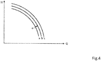
- Fig. 4 shows three of the same pumps pump curves a, b and c, which are spaced apart and do not match. After statistical evaluation of a plurality of such pump curves, a pump curve resulting from the mean value is stored in the programming of a single pump unit, which has been determined on the basis of a plurality of pump units.
- the method according to the invention can be used not only, as described in the introduction, for typical pump units, which are operated partly with a hydraulic sensor and partly without a hydraulic sensor (pressure or flow sensor), by comparing the operating points modeled based on the electrical values With the sensory determined actual operating points with respect to the model calculation can be significantly specified, it can thus also the pump units underlying pump curves are placed on a much wider statistical foundation than is possible with the complex but compared few laboratory measurements.
- the flow rate q can be calculated by the pressure difference ⁇ p. From the equation (2), it is possible to calculate the flow rate q from the pump power P and the pump speed n. These calculations depend on the parameters a h2 to a h0 and a t2 to a t0 . When both the power P and the differential pressure ⁇ p and the rotational speed n are known, the flow rate q can be calculated as follows.
- the flow calculation depends on the parameters ⁇ 1 to ⁇ 6 , which are typically determined by tests manufacturer. This work is time consuming and expensive. For this reason, these parameters are usually only available for some pumps and are interpolated for others.
- Fig. 4 shows which three pump curves a, b and c represents three different type-identical pumps, these curves have a scattering e between the pump a and the pump b. Looking at the pumps a and c, this scatter is even greater. So if only one pump, for example, the pump b is measured, so there is a significant dispersion in the pump curves even with the same type pumps.
- the parameters of the above equations on the basis of the plurality of type-identical pump units and by statistical evaluation to determine comparatively accurately, and if possible using the data of pump units, in which differential pressure ⁇ p and / or flow q are determined by sensors. Since the power and the speed of the pump are always available due to the corresponding motor data, this information can be used to improve equation (2) so that parameters are found which describe the average electrical / hydraulic behavior of the respective pump unit type. If a flow sensor is present in addition to the differential pressure sensor, the parameters of equations (1) and (3) can be determined.
- the determination is carried out using known mathematical methods, for example by linear regression. In this case, a continuous updating of the parameters of equation (1) takes place.
- the searched parameters are collected as parameter vectors and updated with known methods, so that it is not necessary to recalculate them from the entire data each time a parameter set is requested.
- the data set to be used is used in the already available model and checked to determine whether the value thus determined lies within the standard deviation of the model used. If this is not the case, the data set is not used for further determination of the parameters. It makes sense to use not only type-identical pump units to determine the parameters, but, where possible, those that are used comparably, and have about the same hours of operation, so as to be able to compensate for any signs of wear.
- the method according to the invention can also be used, for example, to supply the energetically favorable switching points in booster pumps in which a group 5 of pump units 1a are operated in parallel, and the pumps are switched on and off as required by the common electronic controller 6 determine.
- the connection is often made according to simple rules, for example, the next pump is switched on when the already running pumps have reached 95% of their maximum speed. This is energetically often not favorable.
- the data of three pump unit groups are evaluated in their time course, as based on Fig. 3 is shown.
- the three pump unit groups have different switching speeds n
- the pump unit group 1 (pumping station 1) has a switching speed n 1, which is lower than the shift speed n 2 of the pump unit group 2 (pumping station 2), which in turn is lower than the switching speed n 3 of the pump unit group 3 (pumping station 3). If one then compares the power consumption P (power) over the time T (time) as a function of the current pump number s, it becomes clear that the pumping station 2 is the energetic one most favorable switching speed n having.
- This switching threshold which takes place by evaluating the operating data on the basis of the database 8, can be automated and used to adjust the switching speed of such pumping stations, either during installation or after a certain time. Since these settings depend on the pressure conditions at the input of the booster pump, the switching speed must always be changed when the input pressure changes significantly n be determined again. Then it looks for comparable data of booster pumps in the database and based on this comparison, which is similar to that of Fig. 3 described, then again calculates the most favorable for the pumping station switching speed.
Landscapes
- Engineering & Computer Science (AREA)
- Mechanical Engineering (AREA)
- General Engineering & Computer Science (AREA)
- Physics & Mathematics (AREA)
- General Physics & Mathematics (AREA)
- Automation & Control Theory (AREA)
- Computer Hardware Design (AREA)
- Control Of Positive-Displacement Pumps (AREA)
- Control Of Non-Positive-Displacement Pumps (AREA)
Priority Applications (4)
| Application Number | Priority Date | Filing Date | Title |
|---|---|---|---|
| EP16207135.1A EP3242035B1 (fr) | 2016-12-28 | 2016-12-28 | Procédé de fonctionnement d'au moins un groupe motopompe parmi une pluralité de groupes motopompe |
| US15/855,271 US10824173B2 (en) | 2016-12-28 | 2017-12-27 | Method for operating at least one pump assembly of a multitude of pump assemblies |
| RU2017146137A RU2681394C1 (ru) | 2016-12-28 | 2017-12-27 | Способ эксплуатации по меньшей мере одного насосного агрегата из множества насосных агрегатов |
| CN201711456383.3A CN108252932B (zh) | 2016-12-28 | 2017-12-28 | 用于运行多个泵单元中的至少一个泵单元的方法 |
Applications Claiming Priority (1)
| Application Number | Priority Date | Filing Date | Title |
|---|---|---|---|
| EP16207135.1A EP3242035B1 (fr) | 2016-12-28 | 2016-12-28 | Procédé de fonctionnement d'au moins un groupe motopompe parmi une pluralité de groupes motopompe |
Publications (2)
| Publication Number | Publication Date |
|---|---|
| EP3242035A1 true EP3242035A1 (fr) | 2017-11-08 |
| EP3242035B1 EP3242035B1 (fr) | 2021-08-18 |
Family
ID=57614284
Family Applications (1)
| Application Number | Title | Priority Date | Filing Date |
|---|---|---|---|
| EP16207135.1A Active EP3242035B1 (fr) | 2016-12-28 | 2016-12-28 | Procédé de fonctionnement d'au moins un groupe motopompe parmi une pluralité de groupes motopompe |
Country Status (4)
| Country | Link |
|---|---|
| US (1) | US10824173B2 (fr) |
| EP (1) | EP3242035B1 (fr) |
| CN (1) | CN108252932B (fr) |
| RU (1) | RU2681394C1 (fr) |
Cited By (1)
| Publication number | Priority date | Publication date | Assignee | Title |
|---|---|---|---|---|
| EP3546751A1 (fr) * | 2018-03-30 | 2019-10-02 | Cole-Parmer Instrument Company LLC | Procédé de surveillance et de commande d'appareil de manipulation de fluide |
Families Citing this family (3)
| Publication number | Priority date | Publication date | Assignee | Title |
|---|---|---|---|---|
| RS63767B1 (sr) * | 2019-03-06 | 2022-12-30 | Komax Holding Ag | Računarski implementiran postupak za kontrolu većeg broja uređaja za obradu kablova i kontrolni sistem |
| IT201900015674A1 (it) * | 2019-09-05 | 2021-03-05 | Calpeda A Spa | Metodo di protezione e di gestione di azionamento di un sistema di pressurizzazione |
| CN117536846B (zh) * | 2024-01-09 | 2024-04-30 | 佛山市钒音科技有限公司 | 一种多变频水泵控制方法及系统 |
Citations (4)
| Publication number | Priority date | Publication date | Assignee | Title |
|---|---|---|---|---|
| EP2151578A1 (fr) * | 2008-08-04 | 2010-02-10 | Grundfos Management A/S | Agrégat de pompe de recirculation |
| CN202284531U (zh) | 2011-09-20 | 2012-06-27 | 朗德华信(北京)自控技术有限公司 | 基于云计算的水泵管理控制系统 |
| WO2013041616A1 (fr) * | 2011-09-20 | 2013-03-28 | Grundfos Holding A/S | Unité de pompe |
| WO2013149281A1 (fr) * | 2012-03-14 | 2013-10-10 | South East Water Corporation | Système et procédé de commande d'un égout sous pression |
Family Cites Families (6)
| Publication number | Priority date | Publication date | Assignee | Title |
|---|---|---|---|---|
| US6907383B2 (en) * | 1996-03-28 | 2005-06-14 | Rosemount Inc. | Flow diagnostic system |
| US8914300B2 (en) * | 2001-08-10 | 2014-12-16 | Rockwell Automation Technologies, Inc. | System and method for dynamic multi-objective optimization of machine selection, integration and utilization |
| JP5304766B2 (ja) * | 2010-10-26 | 2013-10-02 | 株式会社デンソー | 流量測定装置 |
| WO2014083340A1 (fr) * | 2012-11-30 | 2014-06-05 | Imperial Innovations Limited | Dispositif, procédé et système pour contrôler un réseau de conduits acheminant un fluide |
| US20150316919A1 (en) * | 2013-05-16 | 2015-11-05 | HYTORC Division Unex Corporation | Multifunctional Hydraulic Drive Unit |
| US20150095100A1 (en) * | 2013-09-30 | 2015-04-02 | Ge Oil & Gas Esp, Inc. | System and Method for Integrated Risk and Health Management of Electric Submersible Pumping Systems |
-
2016
- 2016-12-28 EP EP16207135.1A patent/EP3242035B1/fr active Active
-
2017
- 2017-12-27 US US15/855,271 patent/US10824173B2/en active Active
- 2017-12-27 RU RU2017146137A patent/RU2681394C1/ru active
- 2017-12-28 CN CN201711456383.3A patent/CN108252932B/zh active Active
Patent Citations (4)
| Publication number | Priority date | Publication date | Assignee | Title |
|---|---|---|---|---|
| EP2151578A1 (fr) * | 2008-08-04 | 2010-02-10 | Grundfos Management A/S | Agrégat de pompe de recirculation |
| CN202284531U (zh) | 2011-09-20 | 2012-06-27 | 朗德华信(北京)自控技术有限公司 | 基于云计算的水泵管理控制系统 |
| WO2013041616A1 (fr) * | 2011-09-20 | 2013-03-28 | Grundfos Holding A/S | Unité de pompe |
| WO2013149281A1 (fr) * | 2012-03-14 | 2013-10-10 | South East Water Corporation | Système et procédé de commande d'un égout sous pression |
Cited By (1)
| Publication number | Priority date | Publication date | Assignee | Title |
|---|---|---|---|---|
| EP3546751A1 (fr) * | 2018-03-30 | 2019-10-02 | Cole-Parmer Instrument Company LLC | Procédé de surveillance et de commande d'appareil de manipulation de fluide |
Also Published As
| Publication number | Publication date |
|---|---|
| CN108252932A (zh) | 2018-07-06 |
| CN108252932B (zh) | 2020-11-03 |
| EP3242035B1 (fr) | 2021-08-18 |
| US20180181145A1 (en) | 2018-06-28 |
| RU2681394C1 (ru) | 2019-03-06 |
| US10824173B2 (en) | 2020-11-03 |
Similar Documents
| Publication | Publication Date | Title |
|---|---|---|
| EP2258949B1 (fr) | Procédé de détermination de valeurs caractéristiques, notamment de valeurs, notamment de paramètres, d'un agrégat de pompe centrifuge entraîné par moteur électrique intégré dans une installation | |
| EP2024712B1 (fr) | Dispositif pour la transmission de valeurs de mesure | |
| EP3242035B1 (fr) | Procédé de fonctionnement d'au moins un groupe motopompe parmi une pluralité de groupes motopompe | |
| EP3729040A1 (fr) | Procédé basé sur un modèle et système de surveillance d'état d'un palier lisse, en particulier pour des éoliennes | |
| DE102016121744A1 (de) | Anomalitätsanalysesystem und Analysegerät | |
| EP2354555B2 (fr) | Procédé d'optimisation de l'énergie de pompes | |
| DE112013004970T5 (de) | Drucksteuerung mit Hilfe eines Phasenstromes und anfänglicher Einstellung bei einer Fahrzeugbaureihe | |
| DE10310116A1 (de) | Risikominimierung und Wartungsoptimierung durch Ermittlung von Schädigungsanteilen aus Betriebsdaten | |
| EP3291945B1 (fr) | Dispositif de lubrification en quantité minimale | |
| DE112010003299T5 (de) | Steuerung für die Ölbetriebstemperatur einer hydraulischen Antriebseinrichtung | |
| DE102011050017A1 (de) | Steuermittel zum Ansteuern eines Frequenzumrichters sowie Ansteuerverfahren | |
| EP2039939B1 (fr) | Procédé de surveillance d'un dispositif de transformation d'énergie | |
| WO2014023642A1 (fr) | Procédé pour détecter le débit volumique d'une pompe centrifuge | |
| EP3403245B1 (fr) | Composant de vehicule sur rails et procede de production d'un parcours de vie d'un composant de machine et procede de service destine a l'entretien | |
| EP3593103B1 (fr) | Procédé pour déterminer la température du fluide transporté dans une pompe de circulation et pompe de circulation | |
| EP4150235B1 (fr) | Procédé de détermination d'un état d'usure actuel d'une machine hydrostatique | |
| DE102007010768A1 (de) | Verfahren für die Optimierung der Ventilstellung und der Pumpendrehzahl in einem Ventilsystem mit PID-Regelung ohne die Verwendung externer Signale | |
| EP0751446A2 (fr) | Méthode et dispositif de surveillance d'unités d'un système | |
| DE102019116664A1 (de) | Verfahren zur applikationsspezifischen Anpassung eines Sensors an eine Prozessumgebung der Automatisierungstechnik | |
| DE102019204934A1 (de) | Verfahren zum Regeln eines Elektromotors, Regeleinrichtung sowie entsprechende Systeme | |
| DE10157143A1 (de) | Wartungsintervallanzeige für Pumpen | |
| EP2354554B1 (fr) | Procédé de détermination de la relation fonctionnelle de pompes | |
| DE102006045022A1 (de) | Anordnung mit Vakuumgerät und Verfahren zu derem Betrieb | |
| WO2020011481A1 (fr) | Procédé de paramétrage d'un système de capteurs | |
| DE102017126341A1 (de) | Verfahren und Vorrichtung zur Bestimmung eines Verschleißzustands in einer Hydrostatpumpe |
Legal Events
| Date | Code | Title | Description |
|---|---|---|---|
| PUAI | Public reference made under article 153(3) epc to a published international application that has entered the european phase |
Free format text: ORIGINAL CODE: 0009012 |
|
| STAA | Information on the status of an ep patent application or granted ep patent |
Free format text: STATUS: THE APPLICATION HAS BEEN PUBLISHED |
|
| AK | Designated contracting states |
Kind code of ref document: A1 Designated state(s): AL AT BE BG CH CY CZ DE DK EE ES FI FR GB GR HR HU IE IS IT LI LT LU LV MC MK MT NL NO PL PT RO RS SE SI SK SM TR |
|
| AX | Request for extension of the european patent |
Extension state: BA ME |
|
| STAA | Information on the status of an ep patent application or granted ep patent |
Free format text: STATUS: REQUEST FOR EXAMINATION WAS MADE |
|
| 17P | Request for examination filed |
Effective date: 20180507 |
|
| RBV | Designated contracting states (corrected) |
Designated state(s): AL AT BE BG CH CY CZ DE DK EE ES FI FR GB GR HR HU IE IS IT LI LT LU LV MC MK MT NL NO PL PT RO RS SE SI SK SM TR |
|
| STAA | Information on the status of an ep patent application or granted ep patent |
Free format text: STATUS: EXAMINATION IS IN PROGRESS |
|
| 17Q | First examination report despatched |
Effective date: 20200414 |
|
| STAA | Information on the status of an ep patent application or granted ep patent |
Free format text: STATUS: EXAMINATION IS IN PROGRESS |
|
| GRAP | Despatch of communication of intention to grant a patent |
Free format text: ORIGINAL CODE: EPIDOSNIGR1 |
|
| STAA | Information on the status of an ep patent application or granted ep patent |
Free format text: STATUS: GRANT OF PATENT IS INTENDED |
|
| INTG | Intention to grant announced |
Effective date: 20210318 |
|
| GRAS | Grant fee paid |
Free format text: ORIGINAL CODE: EPIDOSNIGR3 |
|
| GRAA | (expected) grant |
Free format text: ORIGINAL CODE: 0009210 |
|
| STAA | Information on the status of an ep patent application or granted ep patent |
Free format text: STATUS: THE PATENT HAS BEEN GRANTED |
|
| AK | Designated contracting states |
Kind code of ref document: B1 Designated state(s): AL AT BE BG CH CY CZ DE DK EE ES FI FR GB GR HR HU IE IS IT LI LT LU LV MC MK MT NL NO PL PT RO RS SE SI SK SM TR |
|
| REG | Reference to a national code |
Ref country code: GB Ref legal event code: FG4D Free format text: NOT ENGLISH |
|
| REG | Reference to a national code |
Ref country code: CH Ref legal event code: EP |
|
| REG | Reference to a national code |
Ref country code: DE Ref legal event code: R096 Ref document number: 502016013642 Country of ref document: DE |
|
| REG | Reference to a national code |
Ref country code: IE Ref legal event code: FG4D Free format text: LANGUAGE OF EP DOCUMENT: GERMAN Ref country code: AT Ref legal event code: REF Ref document number: 1421886 Country of ref document: AT Kind code of ref document: T Effective date: 20210915 |
|
| REG | Reference to a national code |
Ref country code: LT Ref legal event code: MG9D |
|
| REG | Reference to a national code |
Ref country code: NL Ref legal event code: MP Effective date: 20210818 |
|
| PG25 | Lapsed in a contracting state [announced via postgrant information from national office to epo] |
Ref country code: SE Free format text: LAPSE BECAUSE OF FAILURE TO SUBMIT A TRANSLATION OF THE DESCRIPTION OR TO PAY THE FEE WITHIN THE PRESCRIBED TIME-LIMIT Effective date: 20210818 Ref country code: RS Free format text: LAPSE BECAUSE OF FAILURE TO SUBMIT A TRANSLATION OF THE DESCRIPTION OR TO PAY THE FEE WITHIN THE PRESCRIBED TIME-LIMIT Effective date: 20210818 Ref country code: HR Free format text: LAPSE BECAUSE OF FAILURE TO SUBMIT A TRANSLATION OF THE DESCRIPTION OR TO PAY THE FEE WITHIN THE PRESCRIBED TIME-LIMIT Effective date: 20210818 Ref country code: ES Free format text: LAPSE BECAUSE OF FAILURE TO SUBMIT A TRANSLATION OF THE DESCRIPTION OR TO PAY THE FEE WITHIN THE PRESCRIBED TIME-LIMIT Effective date: 20210818 Ref country code: FI Free format text: LAPSE BECAUSE OF FAILURE TO SUBMIT A TRANSLATION OF THE DESCRIPTION OR TO PAY THE FEE WITHIN THE PRESCRIBED TIME-LIMIT Effective date: 20210818 Ref country code: PT Free format text: LAPSE BECAUSE OF FAILURE TO SUBMIT A TRANSLATION OF THE DESCRIPTION OR TO PAY THE FEE WITHIN THE PRESCRIBED TIME-LIMIT Effective date: 20211220 Ref country code: NO Free format text: LAPSE BECAUSE OF FAILURE TO SUBMIT A TRANSLATION OF THE DESCRIPTION OR TO PAY THE FEE WITHIN THE PRESCRIBED TIME-LIMIT Effective date: 20211118 Ref country code: LT Free format text: LAPSE BECAUSE OF FAILURE TO SUBMIT A TRANSLATION OF THE DESCRIPTION OR TO PAY THE FEE WITHIN THE PRESCRIBED TIME-LIMIT Effective date: 20210818 Ref country code: BG Free format text: LAPSE BECAUSE OF FAILURE TO SUBMIT A TRANSLATION OF THE DESCRIPTION OR TO PAY THE FEE WITHIN THE PRESCRIBED TIME-LIMIT Effective date: 20211118 |
|
| PG25 | Lapsed in a contracting state [announced via postgrant information from national office to epo] |
Ref country code: PL Free format text: LAPSE BECAUSE OF FAILURE TO SUBMIT A TRANSLATION OF THE DESCRIPTION OR TO PAY THE FEE WITHIN THE PRESCRIBED TIME-LIMIT Effective date: 20210818 Ref country code: LV Free format text: LAPSE BECAUSE OF FAILURE TO SUBMIT A TRANSLATION OF THE DESCRIPTION OR TO PAY THE FEE WITHIN THE PRESCRIBED TIME-LIMIT Effective date: 20210818 Ref country code: GR Free format text: LAPSE BECAUSE OF FAILURE TO SUBMIT A TRANSLATION OF THE DESCRIPTION OR TO PAY THE FEE WITHIN THE PRESCRIBED TIME-LIMIT Effective date: 20211119 |
|
| PG25 | Lapsed in a contracting state [announced via postgrant information from national office to epo] |
Ref country code: NL Free format text: LAPSE BECAUSE OF FAILURE TO SUBMIT A TRANSLATION OF THE DESCRIPTION OR TO PAY THE FEE WITHIN THE PRESCRIBED TIME-LIMIT Effective date: 20210818 |
|
| PG25 | Lapsed in a contracting state [announced via postgrant information from national office to epo] |
Ref country code: DK Free format text: LAPSE BECAUSE OF FAILURE TO SUBMIT A TRANSLATION OF THE DESCRIPTION OR TO PAY THE FEE WITHIN THE PRESCRIBED TIME-LIMIT Effective date: 20210818 |
|
| REG | Reference to a national code |
Ref country code: DE Ref legal event code: R097 Ref document number: 502016013642 Country of ref document: DE |
|
| PG25 | Lapsed in a contracting state [announced via postgrant information from national office to epo] |
Ref country code: SM Free format text: LAPSE BECAUSE OF FAILURE TO SUBMIT A TRANSLATION OF THE DESCRIPTION OR TO PAY THE FEE WITHIN THE PRESCRIBED TIME-LIMIT Effective date: 20210818 Ref country code: SK Free format text: LAPSE BECAUSE OF FAILURE TO SUBMIT A TRANSLATION OF THE DESCRIPTION OR TO PAY THE FEE WITHIN THE PRESCRIBED TIME-LIMIT Effective date: 20210818 Ref country code: RO Free format text: LAPSE BECAUSE OF FAILURE TO SUBMIT A TRANSLATION OF THE DESCRIPTION OR TO PAY THE FEE WITHIN THE PRESCRIBED TIME-LIMIT Effective date: 20210818 Ref country code: EE Free format text: LAPSE BECAUSE OF FAILURE TO SUBMIT A TRANSLATION OF THE DESCRIPTION OR TO PAY THE FEE WITHIN THE PRESCRIBED TIME-LIMIT Effective date: 20210818 Ref country code: CZ Free format text: LAPSE BECAUSE OF FAILURE TO SUBMIT A TRANSLATION OF THE DESCRIPTION OR TO PAY THE FEE WITHIN THE PRESCRIBED TIME-LIMIT Effective date: 20210818 Ref country code: AL Free format text: LAPSE BECAUSE OF FAILURE TO SUBMIT A TRANSLATION OF THE DESCRIPTION OR TO PAY THE FEE WITHIN THE PRESCRIBED TIME-LIMIT Effective date: 20210818 |
|
| PLBE | No opposition filed within time limit |
Free format text: ORIGINAL CODE: 0009261 |
|
| STAA | Information on the status of an ep patent application or granted ep patent |
Free format text: STATUS: NO OPPOSITION FILED WITHIN TIME LIMIT |
|
| 26N | No opposition filed |
Effective date: 20220519 |
|
| PG25 | Lapsed in a contracting state [announced via postgrant information from national office to epo] |
Ref country code: MC Free format text: LAPSE BECAUSE OF FAILURE TO SUBMIT A TRANSLATION OF THE DESCRIPTION OR TO PAY THE FEE WITHIN THE PRESCRIBED TIME-LIMIT Effective date: 20210818 |
|
| REG | Reference to a national code |
Ref country code: CH Ref legal event code: PL |
|
| PG25 | Lapsed in a contracting state [announced via postgrant information from national office to epo] |
Ref country code: SI Free format text: LAPSE BECAUSE OF FAILURE TO SUBMIT A TRANSLATION OF THE DESCRIPTION OR TO PAY THE FEE WITHIN THE PRESCRIBED TIME-LIMIT Effective date: 20210818 |
|
| REG | Reference to a national code |
Ref country code: BE Ref legal event code: MM Effective date: 20211231 |
|
| REG | Reference to a national code |
Ref country code: DE Ref legal event code: R082 Ref document number: 502016013642 Country of ref document: DE |
|
| PG25 | Lapsed in a contracting state [announced via postgrant information from national office to epo] |
Ref country code: LU Free format text: LAPSE BECAUSE OF NON-PAYMENT OF DUE FEES Effective date: 20211228 Ref country code: IE Free format text: LAPSE BECAUSE OF NON-PAYMENT OF DUE FEES Effective date: 20211228 |
|
| PG25 | Lapsed in a contracting state [announced via postgrant information from national office to epo] |
Ref country code: BE Free format text: LAPSE BECAUSE OF NON-PAYMENT OF DUE FEES Effective date: 20211231 |
|
| PG25 | Lapsed in a contracting state [announced via postgrant information from national office to epo] |
Ref country code: LI Free format text: LAPSE BECAUSE OF NON-PAYMENT OF DUE FEES Effective date: 20211231 Ref country code: CH Free format text: LAPSE BECAUSE OF NON-PAYMENT OF DUE FEES Effective date: 20211231 |
|
| REG | Reference to a national code |
Ref country code: AT Ref legal event code: MM01 Ref document number: 1421886 Country of ref document: AT Kind code of ref document: T Effective date: 20211228 |
|
| PG25 | Lapsed in a contracting state [announced via postgrant information from national office to epo] |
Ref country code: AT Free format text: LAPSE BECAUSE OF NON-PAYMENT OF DUE FEES Effective date: 20211228 |
|
| PG25 | Lapsed in a contracting state [announced via postgrant information from national office to epo] |
Ref country code: HU Free format text: LAPSE BECAUSE OF FAILURE TO SUBMIT A TRANSLATION OF THE DESCRIPTION OR TO PAY THE FEE WITHIN THE PRESCRIBED TIME-LIMIT; INVALID AB INITIO Effective date: 20161228 |
|
| PG25 | Lapsed in a contracting state [announced via postgrant information from national office to epo] |
Ref country code: CY Free format text: LAPSE BECAUSE OF FAILURE TO SUBMIT A TRANSLATION OF THE DESCRIPTION OR TO PAY THE FEE WITHIN THE PRESCRIBED TIME-LIMIT Effective date: 20210818 |
|
| PGFP | Annual fee paid to national office [announced via postgrant information from national office to epo] |
Ref country code: GB Payment date: 20231220 Year of fee payment: 8 |
|
| PGFP | Annual fee paid to national office [announced via postgrant information from national office to epo] |
Ref country code: IT Payment date: 20231228 Year of fee payment: 8 Ref country code: FR Payment date: 20231221 Year of fee payment: 8 Ref country code: DE Payment date: 20231214 Year of fee payment: 8 |
|
| PG25 | Lapsed in a contracting state [announced via postgrant information from national office to epo] |
Ref country code: MK Free format text: LAPSE BECAUSE OF FAILURE TO SUBMIT A TRANSLATION OF THE DESCRIPTION OR TO PAY THE FEE WITHIN THE PRESCRIBED TIME-LIMIT Effective date: 20210818 |