EP3242007A1 - System und verfahren zur modellierung der leistungsabgabe eines motors - Google Patents
System und verfahren zur modellierung der leistungsabgabe eines motors Download PDFInfo
- Publication number
- EP3242007A1 EP3242007A1 EP17168550.6A EP17168550A EP3242007A1 EP 3242007 A1 EP3242007 A1 EP 3242007A1 EP 17168550 A EP17168550 A EP 17168550A EP 3242007 A1 EP3242007 A1 EP 3242007A1
- Authority
- EP
- European Patent Office
- Prior art keywords
- engine
- power
- power augmentation
- controller
- operating parameter
- Prior art date
- Legal status (The legal status is an assumption and is not a legal conclusion. Google has not performed a legal analysis and makes no representation as to the accuracy of the status listed.)
- Withdrawn
Links
- 238000000034 method Methods 0.000 title claims description 59
- 230000003416 augmentation Effects 0.000 claims abstract description 304
- 230000004913 activation Effects 0.000 claims abstract description 55
- 230000008859 change Effects 0.000 claims abstract description 45
- 239000007800 oxidant agent Substances 0.000 claims description 87
- 230000001590 oxidative effect Effects 0.000 claims description 85
- 239000000446 fuel Substances 0.000 claims description 41
- XLYOFNOQVPJJNP-UHFFFAOYSA-N water Substances O XLYOFNOQVPJJNP-UHFFFAOYSA-N 0.000 claims description 23
- 239000000203 mixture Substances 0.000 claims description 18
- 238000002347 injection Methods 0.000 claims description 9
- 239000007924 injection Substances 0.000 claims description 9
- 230000015556 catabolic process Effects 0.000 claims description 6
- 238000006731 degradation reaction Methods 0.000 claims description 6
- 239000007789 gas Substances 0.000 description 29
- 239000012530 fluid Substances 0.000 description 11
- 238000010586 diagram Methods 0.000 description 8
- 238000012549 training Methods 0.000 description 8
- QVGXLLKOCUKJST-UHFFFAOYSA-N atomic oxygen Chemical compound [O] QVGXLLKOCUKJST-UHFFFAOYSA-N 0.000 description 7
- 239000001301 oxygen Substances 0.000 description 7
- 229910052760 oxygen Inorganic materials 0.000 description 7
- 239000003570 air Substances 0.000 description 6
- 239000012080 ambient air Substances 0.000 description 6
- 238000002485 combustion reaction Methods 0.000 description 6
- 230000006399 behavior Effects 0.000 description 4
- 230000005611 electricity Effects 0.000 description 4
- 239000013618 particulate matter Substances 0.000 description 4
- 238000000611 regression analysis Methods 0.000 description 4
- 238000012360 testing method Methods 0.000 description 4
- 230000006870 function Effects 0.000 description 3
- 230000003287 optical effect Effects 0.000 description 3
- IJGRMHOSHXDMSA-UHFFFAOYSA-N Atomic nitrogen Chemical compound N#N IJGRMHOSHXDMSA-UHFFFAOYSA-N 0.000 description 2
- 238000013473 artificial intelligence Methods 0.000 description 2
- 238000013528 artificial neural network Methods 0.000 description 2
- 230000008901 benefit Effects 0.000 description 2
- 238000013145 classification model Methods 0.000 description 2
- 238000007418 data mining Methods 0.000 description 2
- 238000013461 design Methods 0.000 description 2
- 238000011161 development Methods 0.000 description 2
- 230000001939 inductive effect Effects 0.000 description 2
- 239000007788 liquid Substances 0.000 description 2
- 238000010801 machine learning Methods 0.000 description 2
- 238000004519 manufacturing process Methods 0.000 description 2
- VNWKTOKETHGBQD-UHFFFAOYSA-N methane Chemical compound C VNWKTOKETHGBQD-UHFFFAOYSA-N 0.000 description 2
- 230000009467 reduction Effects 0.000 description 2
- 238000004088 simulation Methods 0.000 description 2
- 238000013179 statistical model Methods 0.000 description 2
- 230000000007 visual effect Effects 0.000 description 2
- UFHFLCQGNIYNRP-UHFFFAOYSA-N Hydrogen Chemical compound [H][H] UFHFLCQGNIYNRP-UHFFFAOYSA-N 0.000 description 1
- 230000003213 activating effect Effects 0.000 description 1
- 230000003044 adaptive effect Effects 0.000 description 1
- 239000000654 additive Substances 0.000 description 1
- 230000003190 augmentative effect Effects 0.000 description 1
- 239000012636 effector Substances 0.000 description 1
- 230000000694 effects Effects 0.000 description 1
- 230000008020 evaporation Effects 0.000 description 1
- 238000001704 evaporation Methods 0.000 description 1
- 238000010304 firing Methods 0.000 description 1
- 230000036541 health Effects 0.000 description 1
- 239000001257 hydrogen Substances 0.000 description 1
- 229910052739 hydrogen Inorganic materials 0.000 description 1
- 239000003345 natural gas Substances 0.000 description 1
- 229910052757 nitrogen Inorganic materials 0.000 description 1
- 238000010248 power generation Methods 0.000 description 1
- 238000011084 recovery Methods 0.000 description 1
- 239000002699 waste material Substances 0.000 description 1
Images

Classifications
-
- F—MECHANICAL ENGINEERING; LIGHTING; HEATING; WEAPONS; BLASTING
- F02—COMBUSTION ENGINES; HOT-GAS OR COMBUSTION-PRODUCT ENGINE PLANTS
- F02D—CONTROLLING COMBUSTION ENGINES
- F02D41/00—Electrical control of supply of combustible mixture or its constituents
- F02D41/02—Circuit arrangements for generating control signals
- F02D41/14—Introducing closed-loop corrections
- F02D41/1401—Introducing closed-loop corrections characterised by the control or regulation method
-
- G—PHYSICS
- G01—MEASURING; TESTING
- G01M—TESTING STATIC OR DYNAMIC BALANCE OF MACHINES OR STRUCTURES; TESTING OF STRUCTURES OR APPARATUS, NOT OTHERWISE PROVIDED FOR
- G01M15/00—Testing of engines
- G01M15/14—Testing gas-turbine engines or jet-propulsion engines
-
- F—MECHANICAL ENGINEERING; LIGHTING; HEATING; WEAPONS; BLASTING
- F01—MACHINES OR ENGINES IN GENERAL; ENGINE PLANTS IN GENERAL; STEAM ENGINES
- F01K—STEAM ENGINE PLANTS; STEAM ACCUMULATORS; ENGINE PLANTS NOT OTHERWISE PROVIDED FOR; ENGINES USING SPECIAL WORKING FLUIDS OR CYCLES
- F01K23/00—Plants characterised by more than one engine delivering power external to the plant, the engines being driven by different fluids
- F01K23/02—Plants characterised by more than one engine delivering power external to the plant, the engines being driven by different fluids the engine cycles being thermally coupled
- F01K23/06—Plants characterised by more than one engine delivering power external to the plant, the engines being driven by different fluids the engine cycles being thermally coupled combustion heat from one cycle heating the fluid in another cycle
- F01K23/10—Plants characterised by more than one engine delivering power external to the plant, the engines being driven by different fluids the engine cycles being thermally coupled combustion heat from one cycle heating the fluid in another cycle with exhaust fluid of one cycle heating the fluid in another cycle
- F01K23/101—Regulating means specially adapted therefor
-
- F—MECHANICAL ENGINEERING; LIGHTING; HEATING; WEAPONS; BLASTING
- F02—COMBUSTION ENGINES; HOT-GAS OR COMBUSTION-PRODUCT ENGINE PLANTS
- F02C—GAS-TURBINE PLANTS; AIR INTAKES FOR JET-PROPULSION PLANTS; CONTROLLING FUEL SUPPLY IN AIR-BREATHING JET-PROPULSION PLANTS
- F02C9/00—Controlling gas-turbine plants; Controlling fuel supply in air- breathing jet-propulsion plants
- F02C9/48—Control of fuel supply conjointly with another control of the plant
- F02C9/50—Control of fuel supply conjointly with another control of the plant with control of working fluid flow
-
- F—MECHANICAL ENGINEERING; LIGHTING; HEATING; WEAPONS; BLASTING
- F02—COMBUSTION ENGINES; HOT-GAS OR COMBUSTION-PRODUCT ENGINE PLANTS
- F02D—CONTROLLING COMBUSTION ENGINES
- F02D41/00—Electrical control of supply of combustible mixture or its constituents
- F02D41/02—Circuit arrangements for generating control signals
- F02D41/14—Introducing closed-loop corrections
- F02D41/1401—Introducing closed-loop corrections characterised by the control or regulation method
- F02D2041/1412—Introducing closed-loop corrections characterised by the control or regulation method using a predictive controller
-
- F—MECHANICAL ENGINEERING; LIGHTING; HEATING; WEAPONS; BLASTING
- F02—COMBUSTION ENGINES; HOT-GAS OR COMBUSTION-PRODUCT ENGINE PLANTS
- F02D—CONTROLLING COMBUSTION ENGINES
- F02D41/00—Electrical control of supply of combustible mixture or its constituents
- F02D41/02—Circuit arrangements for generating control signals
- F02D41/14—Introducing closed-loop corrections
- F02D41/1401—Introducing closed-loop corrections characterised by the control or regulation method
- F02D2041/1433—Introducing closed-loop corrections characterised by the control or regulation method using a model or simulation of the system
-
- F—MECHANICAL ENGINEERING; LIGHTING; HEATING; WEAPONS; BLASTING
- F02—COMBUSTION ENGINES; HOT-GAS OR COMBUSTION-PRODUCT ENGINE PLANTS
- F02D—CONTROLLING COMBUSTION ENGINES
- F02D2200/00—Input parameters for engine control
- F02D2200/02—Input parameters for engine control the parameters being related to the engine
- F02D2200/04—Engine intake system parameters
- F02D2200/0402—Engine intake system parameters the parameter being determined by using a model of the engine intake or its components
-
- F—MECHANICAL ENGINEERING; LIGHTING; HEATING; WEAPONS; BLASTING
- F02—COMBUSTION ENGINES; HOT-GAS OR COMBUSTION-PRODUCT ENGINE PLANTS
- F02D—CONTROLLING COMBUSTION ENGINES
- F02D2200/00—Input parameters for engine control
- F02D2200/02—Input parameters for engine control the parameters being related to the engine
- F02D2200/04—Engine intake system parameters
- F02D2200/0414—Air temperature
-
- F—MECHANICAL ENGINEERING; LIGHTING; HEATING; WEAPONS; BLASTING
- F02—COMBUSTION ENGINES; HOT-GAS OR COMBUSTION-PRODUCT ENGINE PLANTS
- F02D—CONTROLLING COMBUSTION ENGINES
- F02D2200/00—Input parameters for engine control
- F02D2200/02—Input parameters for engine control the parameters being related to the engine
- F02D2200/04—Engine intake system parameters
- F02D2200/0418—Air humidity
-
- F—MECHANICAL ENGINEERING; LIGHTING; HEATING; WEAPONS; BLASTING
- F02—COMBUSTION ENGINES; HOT-GAS OR COMBUSTION-PRODUCT ENGINE PLANTS
- F02D—CONTROLLING COMBUSTION ENGINES
- F02D2200/00—Input parameters for engine control
- F02D2200/70—Input parameters for engine control said parameters being related to the vehicle exterior
- F02D2200/703—Atmospheric pressure
-
- F—MECHANICAL ENGINEERING; LIGHTING; HEATING; WEAPONS; BLASTING
- F02—COMBUSTION ENGINES; HOT-GAS OR COMBUSTION-PRODUCT ENGINE PLANTS
- F02D—CONTROLLING COMBUSTION ENGINES
- F02D2250/00—Engine control related to specific problems or objectives
- F02D2250/18—Control of the engine output torque
-
- F—MECHANICAL ENGINEERING; LIGHTING; HEATING; WEAPONS; BLASTING
- F02—COMBUSTION ENGINES; HOT-GAS OR COMBUSTION-PRODUCT ENGINE PLANTS
- F02D—CONTROLLING COMBUSTION ENGINES
- F02D41/00—Electrical control of supply of combustible mixture or its constituents
- F02D41/0002—Controlling intake air
- F02D41/0007—Controlling intake air for control of turbo-charged or super-charged engines
-
- F—MECHANICAL ENGINEERING; LIGHTING; HEATING; WEAPONS; BLASTING
- F02—COMBUSTION ENGINES; HOT-GAS OR COMBUSTION-PRODUCT ENGINE PLANTS
- F02M—SUPPLYING COMBUSTION ENGINES IN GENERAL WITH COMBUSTIBLE MIXTURES OR CONSTITUENTS THEREOF
- F02M25/00—Engine-pertinent apparatus for adding non-fuel substances or small quantities of secondary fuel to combustion-air, main fuel or fuel-air mixture
- F02M25/022—Adding fuel and water emulsion, water or steam
-
- F—MECHANICAL ENGINEERING; LIGHTING; HEATING; WEAPONS; BLASTING
- F05—INDEXING SCHEMES RELATING TO ENGINES OR PUMPS IN VARIOUS SUBCLASSES OF CLASSES F01-F04
- F05D—INDEXING SCHEME FOR ASPECTS RELATING TO NON-POSITIVE-DISPLACEMENT MACHINES OR ENGINES, GAS-TURBINES OR JET-PROPULSION PLANTS
- F05D2220/00—Application
- F05D2220/30—Application in turbines
- F05D2220/32—Application in turbines in gas turbines
-
- F—MECHANICAL ENGINEERING; LIGHTING; HEATING; WEAPONS; BLASTING
- F05—INDEXING SCHEMES RELATING TO ENGINES OR PUMPS IN VARIOUS SUBCLASSES OF CLASSES F01-F04
- F05D—INDEXING SCHEME FOR ASPECTS RELATING TO NON-POSITIVE-DISPLACEMENT MACHINES OR ENGINES, GAS-TURBINES OR JET-PROPULSION PLANTS
- F05D2260/00—Function
- F05D2260/20—Heat transfer, e.g. cooling
- F05D2260/207—Heat transfer, e.g. cooling using a phase changing mass, e.g. heat absorbing by melting or boiling
-
- F—MECHANICAL ENGINEERING; LIGHTING; HEATING; WEAPONS; BLASTING
- F05—INDEXING SCHEMES RELATING TO ENGINES OR PUMPS IN VARIOUS SUBCLASSES OF CLASSES F01-F04
- F05D—INDEXING SCHEME FOR ASPECTS RELATING TO NON-POSITIVE-DISPLACEMENT MACHINES OR ENGINES, GAS-TURBINES OR JET-PROPULSION PLANTS
- F05D2260/00—Function
- F05D2260/20—Heat transfer, e.g. cooling
- F05D2260/211—Heat transfer, e.g. cooling by intercooling, e.g. during a compression cycle
-
- F—MECHANICAL ENGINEERING; LIGHTING; HEATING; WEAPONS; BLASTING
- F05—INDEXING SCHEMES RELATING TO ENGINES OR PUMPS IN VARIOUS SUBCLASSES OF CLASSES F01-F04
- F05D—INDEXING SCHEME FOR ASPECTS RELATING TO NON-POSITIVE-DISPLACEMENT MACHINES OR ENGINES, GAS-TURBINES OR JET-PROPULSION PLANTS
- F05D2260/00—Function
- F05D2260/20—Heat transfer, e.g. cooling
- F05D2260/212—Heat transfer, e.g. cooling by water injection
-
- F—MECHANICAL ENGINEERING; LIGHTING; HEATING; WEAPONS; BLASTING
- F05—INDEXING SCHEMES RELATING TO ENGINES OR PUMPS IN VARIOUS SUBCLASSES OF CLASSES F01-F04
- F05D—INDEXING SCHEME FOR ASPECTS RELATING TO NON-POSITIVE-DISPLACEMENT MACHINES OR ENGINES, GAS-TURBINES OR JET-PROPULSION PLANTS
- F05D2270/00—Control
- F05D2270/01—Purpose of the control system
- F05D2270/05—Purpose of the control system to affect the output of the engine
- F05D2270/053—Explicitly mentioned power
-
- F—MECHANICAL ENGINEERING; LIGHTING; HEATING; WEAPONS; BLASTING
- F05—INDEXING SCHEMES RELATING TO ENGINES OR PUMPS IN VARIOUS SUBCLASSES OF CLASSES F01-F04
- F05D—INDEXING SCHEME FOR ASPECTS RELATING TO NON-POSITIVE-DISPLACEMENT MACHINES OR ENGINES, GAS-TURBINES OR JET-PROPULSION PLANTS
- F05D2270/00—Control
- F05D2270/30—Control parameters, e.g. input parameters
- F05D2270/304—Spool rotational speed
-
- F—MECHANICAL ENGINEERING; LIGHTING; HEATING; WEAPONS; BLASTING
- F05—INDEXING SCHEMES RELATING TO ENGINES OR PUMPS IN VARIOUS SUBCLASSES OF CLASSES F01-F04
- F05D—INDEXING SCHEME FOR ASPECTS RELATING TO NON-POSITIVE-DISPLACEMENT MACHINES OR ENGINES, GAS-TURBINES OR JET-PROPULSION PLANTS
- F05D2270/00—Control
- F05D2270/30—Control parameters, e.g. input parameters
- F05D2270/306—Mass flow
-
- F—MECHANICAL ENGINEERING; LIGHTING; HEATING; WEAPONS; BLASTING
- F05—INDEXING SCHEMES RELATING TO ENGINES OR PUMPS IN VARIOUS SUBCLASSES OF CLASSES F01-F04
- F05D—INDEXING SCHEME FOR ASPECTS RELATING TO NON-POSITIVE-DISPLACEMENT MACHINES OR ENGINES, GAS-TURBINES OR JET-PROPULSION PLANTS
- F05D2270/00—Control
- F05D2270/30—Control parameters, e.g. input parameters
- F05D2270/311—Air humidity
-
- F—MECHANICAL ENGINEERING; LIGHTING; HEATING; WEAPONS; BLASTING
- F05—INDEXING SCHEMES RELATING TO ENGINES OR PUMPS IN VARIOUS SUBCLASSES OF CLASSES F01-F04
- F05D—INDEXING SCHEME FOR ASPECTS RELATING TO NON-POSITIVE-DISPLACEMENT MACHINES OR ENGINES, GAS-TURBINES OR JET-PROPULSION PLANTS
- F05D2270/00—Control
- F05D2270/30—Control parameters, e.g. input parameters
- F05D2270/312—Air pressure
-
- F—MECHANICAL ENGINEERING; LIGHTING; HEATING; WEAPONS; BLASTING
- F05—INDEXING SCHEMES RELATING TO ENGINES OR PUMPS IN VARIOUS SUBCLASSES OF CLASSES F01-F04
- F05D—INDEXING SCHEME FOR ASPECTS RELATING TO NON-POSITIVE-DISPLACEMENT MACHINES OR ENGINES, GAS-TURBINES OR JET-PROPULSION PLANTS
- F05D2270/00—Control
- F05D2270/30—Control parameters, e.g. input parameters
- F05D2270/313—Air temperature
-
- F—MECHANICAL ENGINEERING; LIGHTING; HEATING; WEAPONS; BLASTING
- F05—INDEXING SCHEMES RELATING TO ENGINES OR PUMPS IN VARIOUS SUBCLASSES OF CLASSES F01-F04
- F05D—INDEXING SCHEME FOR ASPECTS RELATING TO NON-POSITIVE-DISPLACEMENT MACHINES OR ENGINES, GAS-TURBINES OR JET-PROPULSION PLANTS
- F05D2270/00—Control
- F05D2270/30—Control parameters, e.g. input parameters
- F05D2270/335—Output power or torque
-
- F—MECHANICAL ENGINEERING; LIGHTING; HEATING; WEAPONS; BLASTING
- F05—INDEXING SCHEMES RELATING TO ENGINES OR PUMPS IN VARIOUS SUBCLASSES OF CLASSES F01-F04
- F05D—INDEXING SCHEME FOR ASPECTS RELATING TO NON-POSITIVE-DISPLACEMENT MACHINES OR ENGINES, GAS-TURBINES OR JET-PROPULSION PLANTS
- F05D2270/00—Control
- F05D2270/40—Type of control system
- F05D2270/44—Type of control system active, predictive, or anticipative
-
- F—MECHANICAL ENGINEERING; LIGHTING; HEATING; WEAPONS; BLASTING
- F05—INDEXING SCHEMES RELATING TO ENGINES OR PUMPS IN VARIOUS SUBCLASSES OF CLASSES F01-F04
- F05D—INDEXING SCHEME FOR ASPECTS RELATING TO NON-POSITIVE-DISPLACEMENT MACHINES OR ENGINES, GAS-TURBINES OR JET-PROPULSION PLANTS
- F05D2270/00—Control
- F05D2270/70—Type of control algorithm
- F05D2270/71—Type of control algorithm synthesized, i.e. parameter computed by a mathematical model
-
- Y—GENERAL TAGGING OF NEW TECHNOLOGICAL DEVELOPMENTS; GENERAL TAGGING OF CROSS-SECTIONAL TECHNOLOGIES SPANNING OVER SEVERAL SECTIONS OF THE IPC; TECHNICAL SUBJECTS COVERED BY FORMER USPC CROSS-REFERENCE ART COLLECTIONS [XRACs] AND DIGESTS
- Y02—TECHNOLOGIES OR APPLICATIONS FOR MITIGATION OR ADAPTATION AGAINST CLIMATE CHANGE
- Y02E—REDUCTION OF GREENHOUSE GAS [GHG] EMISSIONS, RELATED TO ENERGY GENERATION, TRANSMISSION OR DISTRIBUTION
- Y02E20/00—Combustion technologies with mitigation potential
- Y02E20/16—Combined cycle power plant [CCPP], or combined cycle gas turbine [CCGT]
Definitions
- the subject matter disclosed herein relates to engine systems, and more particularly, to methods and systems for modeling power output of engine systems.
- Certain power generation systems may include an engine, such as a gas turbine, and a control system configured to monitor and control operation of the engine.
- the control system may monitor the power output of the engine and may adjust operating parameters of the engine to achieve a desired power output.
- the control system may control a power augmentation system, such as an evaporative cooler, to adjust operating parameters and the power output of the engine.
- the power output of the engine and the performance of the power augmentation system may vary with changes in ambient conditions, such as temperature, pressure, and humidity. As such, it may be difficult to predict a potential increase in power output of the engine gained by activating the power augmentation system.
- a system in one embodiment, includes an engine configured to generate power to drive a load.
- the system also includes a power augmentation system configured to augment a power output of the engine when the power augmentation system is activated.
- the system includes a controller operatively coupled to the power augmentation system.
- the controller is configured to estimate a potential value of a first operating parameter of the engine caused by activation of the power augmentation system by inputting a measured value of the first operating parameter of the engine in a power augmentation model for the power augmentation system.
- the controller is configured to estimate a potential change in the power output of the engine caused by activation of the power augmentation system by inputting the measured value and the potential value of the first operating parameter in an engine performance model for the engine that predicts power output of the engine.
- a system in one embodiment, includes a controller operatively coupled to a power augmentation system configured to increase a power output of an engine.
- the controller is configured to measure a plurality of operating parameters of the engine using a plurality of sensors. Additionally, the controller is configured to estimate a potential value of a first operating parameter of the plurality of operating parameters caused by activation of the power augmentation system by inputting a measured value of the first operating parameter of the plurality of operating parameters in a power augmentation model for the power augmentation system.
- the controller is configured to estimate a potential increase in the power output of the engine caused by activation of the power augmentation system by inputting the measured value and the potential value of the first operating parameter of the plurality of operating parameters in an engine performance model for the engine that predicts power output of the engine.
- a method in one embodiment, includes measuring, via a controller, a plurality of operating parameters of an engine. The method also includes selecting, via the controller, a power augmentation model from two or more power augmentation models for a power augmentation system configured to increase a power output of the engine. Additionally, the method includes estimating, via the controller, a potential value of a first operating parameter of the plurality of operating parameters caused by activation of the power augmentation system by inputting a measured value of the first operating parameter of the plurality of operating parameters in the power augmentation model.
- the method includes estimating, via the controller, a potential increase in the power output of the engine caused by activation of the power augmentation system by inputting the measured value and the potential value of the first operating parameter of the plurality of operating parameters in an engine performance model for the engine that predicts power output of the engine.
- an engine may generate power to drive a load, such as an electrical generator.
- the power output of the engine may vary with changes in operating parameters of the engine.
- the power output of the engine may vary with ambient conditions, such as temperature, pressure, and humidity.
- the performance of the engine may deviate from ideal behavior over time, which may negatively affect the power output of the engine.
- a power augmentation system may be used to augment (e.g., increase) the power output of the engine.
- the power augmentation system may augment the power output of the engine by modifying the value of at least one input operating parameter of the engine.
- the power augmentation system may include an evaporative cooler, a chiller, a water injection unit, or a combination thereof to reduce a temperature of an oxidant (e.g., ambient air) routed to the engine.
- the power augmentation system may include a compressor configured to increase a pressure of the oxidant routed to the engine.
- a controller may use a power augmentation model with at least one input operating parameter to estimate a potential value of the at least one input operating parameter caused by activation of the power augmentation system.
- the power augmentation model may estimate a potential value of a temperature of an oxidant (e.g., ambient air) caused by activation of the power augmentation system (e.g., an evaporative cooler, a chiller, a water injection unit, etc.) based on an initial measured value of the temperature of the oxidant.
- an oxidant e.g., ambient air
- the power augmentation system e.g., an evaporative cooler, a chiller, a water injection unit, etc.
- the power augmentation model may be specific for the power augmentation system.
- the power augmentation model may be generated and trained using historical data from the specific power augmentation system that is used with the engine. In this manner, the power augmentation model may account for performance characteristics and efficiencies that are specific to the power augmentation system, which may increase the accuracy of potential values of operating parameters estimated by the power augmentation model.
- the controller may use estimated potential values of one or more input operating parameters of the engine from the power augmentation model in an engine performance model to estimate a potential change in power output of the engine caused by activation of the power augmentation system.
- the engine performance model may be a physics-based model or an engine simulation model that is configured to predict or estimate potential values of one or more output operating parameters of the engine, such as power output, based on measured or estimated values of one or more input operating parameters.
- the controller may use the engine performance model with the estimated potential values of the one or more input operating parameters of the engine to generate a first estimate of the power output of the engine when the power augmentation system is activated (e.g., when the power augmentation system is modifying the one or more input operating parameters of the engine to augment the power output of the engine). Additionally, the controller may use the engine performance model with corresponding measured values of the one or more input operating parameters of the engine to generate a second estimate of the power output of the engine without the power augmentation system (e.g., when the power augmentation system is deactivated and is not modifying the one or more operating parameters of the engine and is not augmenting the power output of the engine).
- the controller may determine a potential change in the power output of the engine caused by activation of the power augmentation system based on a difference between the first and second estimates. In some embodiments, the controller may provide the potential change in the power output and/or recommendations based on the potential change in the power output to a user, which may facilitate the user in determining whether to activate the power augmentation system.
- the controller may determine one or more performance metrics for the engine using the engine performance model. For example, the controller may use measured values of one or more input operating parameters in the engine performance model to generate estimated values of one or more output operating parameters. Further, the controller may determine one or more performance metrics for the engine based on a comparison of the estimated values of the one or more output operating parameters and corresponding measured values of the one or more output operating parameters. In particular, deviations between the estimated values of the output operating parameters and the actual measured values of the output operating parameters may be used to assess the performance of the engine relative to ideal performance and to determine one or more performance metrics. In some embodiments, the controller may use the one or more performance metrics in the engine performance model when estimating the potential change in the power output of the engine.
- the controller may increase the accuracy of the estimated potential change in the power output of the engine caused by activation of the power augmentation system.
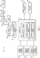
- FIG. 1 is a block diagram of an embodiment of a system 10 with a controller 12 (e.g., processor-based controller) that monitors at least one operating parameter of an engine 14 to estimate a potential increase in the power output of the engine 14 caused by activation of a power augmentation system 16.
- the engine 14 may be a gas turbine engine, a reciprocating internal combustion engine, another heat engine or combustion system, or any other suitable engine.
- the engine 14 may receive an oxidant 18 (e.g., air, oxygen, oxygen enriched air, or oxygen reduced air) and may combust a mixture of the oxidant 18 and fuel to create torque that drives a load 20, such as an electrical generator.
- the engine 14 may induce rotation of a shaft 22 coupled to the load 20, which may use rotational energy of the shaft 22 to generate electricity.
- the power output of the engine 14 may be based on the torque and angular velocity of the shaft 22.
- the system 10 may be a combined cycle power plant that includes a heat recovery steam generator (HRSG) 24 and a steam turbine 26.
- HRSG heat recovery steam generator
- the system 10 may use the thermal energy in exhaust gas 28 from the engine 14 to heat a fluid and create steam 30 in the HRSG 18.
- the steam 30 generated by the HRSG 24 may be supplied to the steam turbine 26, which may use the steam 30 to create torque that drives a load 32, such as an electrical generator.
- the steam turbine 26 may induce rotation of a shaft 34 coupled to the load 32, which may use rotational energy of the shaft 34 to generate electricity.
- the power output of the engine 14 may be based on the torque and angular velocity of the shaft 22, as well as the temperature of the exhaust gas 28.
- the power output of the engine 14, which may be based on the torque and angular velocity of the shaft 22 and/or the temperature of the exhaust gas 28, may vary with certain input operating parameters of the engine 14.
- the power output of the engine 14 may vary based on ambient temperature, the temperature of the oxidant 18, ambient pressure, the pressure of the oxidant 18, ambient relative humidity, the relative humidity of the oxidant 18, and/or an amount of fuel routed to the engine 14.
- the system 10 includes the power augmentation system 16, which may adjust values of one or more input operating parameters of the engine 14 to augment (e.g., increase or decrease) the power output of the engine 14 when the power augmentation system 16 is activated.
- the power augmentation system 16 may be referred to as activated when the power augmentation system 16 is modifying at least one operating parameter of the engine 14. Additionally, as used herein, the power augmentation system 16 may be referred to as deactivated when the power augmentation system 16 is not modifying any operating parameters of the engine 14.
- the power augmentation system 16 may be configured to adjust any suitable operating parameter of the engine 14.
- the power augmentation system 16 may be configured to adjust the temperature, pressure, relative humidity, density, and/or composition (e.g., percent by volume of oxygen, nitrogen, other gases or additives) of the oxidant 18.
- the power augmentation system 16 may be configured to adjust an amount of fuel routed to the engine 14 and/or a temperature of a combustion zone of the engine 14.
- the temperature, pressure, and relative humidity of the oxidant 18 may also be referred to as ambient temperature, ambient pressure, and ambient relative humidity, respectively.
- the power augmentation system 16 may include any suitable component and any number of components (e.g., 1, 2, 3, 4, 5, or more) to adjust values of one or more operating parameters of the engine 14 to augment the power output of the engine 14.
- the power augmentation system 16 may include an evaporative cooler, a chiller, and/or a water supply (e.g., a water injection unit) configured to adjust (e.g., increase or decrease) the temperature, relative humidity, and/or density of the oxidant 18 (e.g., ambient air) that may be delivered to the engine 14.
- the power augmentation system 16 may include a compressor configured to increase a pressure of the oxidant 18 (e.g., ambient air) that may be delivered to the engine 14.
- the power augmentation system 16 may include a fuel supply that is configured to supply a fuel to the engine 14 and/or adjust an amount of fuel supplied to the engine 14.
- a fuel supply that is configured to supply a fuel to the engine 14 and/or adjust an amount of fuel supplied to the engine 14.
- FIG. 2 Various embodiments of the power augmentation system 16 will be discussed in more detail below in FIG. 2 .
- the system 10 also includes the controller 12.
- the controller 12 may include a memory 34 (e.g., one or more memory devices) and a processor 36 (e.g., one or more processors).
- the processor 36 may include one or more general purpose processors, one or more special-purpose microprocessors, one or more application specific integrated circuits (ASICS), one or more reduced instruction set (RISC) processors, or any combination thereof.
- the memory device 34 may include a volatile memory, a nonvolatile memory, a random access memory (RAM), a read-only memory (ROM), a flash memory, a hard drive, or any other suitable optical, magnetic, or solid-state storage medium, or a combination thereof.
- the memory 34 may include one or more tangible, non-transitory, machine-readable media collectively storing instructions and steps written in software code that can be accessed and executed by the processor 36 to perform the methods and control actions described herein.
- the controller 12 monitors at least one operating parameter of the engine 14 to estimate a potential power output of the engine 14 caused by activation of a power augmentation system 16.
- the controller 12 may communicate with and/or control various components of the system 10 in order to monitor at least one operating parameter of the engine 14 and to estimate the potential change in power output of the engine 14.
- the controller 12 may communicate with and/or control the engine 14, the power augmentation system 16, the HRSG 24, the steam turbine 26, the load 20, the load 32, and various components, such as electronics, sensors, valves, pumps, motors, actuators, etc.
- the controller 12 may monitor at least one operating parameter of the engine 14 and estimate the potential power output and/or the potential change in power output of the engine 14 caused by activation of the power augmentation system 16 based at least in part on engine sensor feedback 38, ambient sensor feedback 40, power augmentation system sensor feedback 42, or a combination thereof.
- the system 10 may include any suitable number and type of sensors disposed about (e.g., disposed in, disposed on, disposed proximal to, attached to, integrated with, etc.) the engine 14, the shaft 22, the load 20, the HSRG 24, the steam turbine 26, the load 32, the shaft 34, and/or the power augmentation system 16 or any other suitable location about the system 10 to generate the engine sensor feedback 38, the ambient sensor feedback 40, and/or the power augmentation system sensor feedback 42.
- sensors disposed about (e.g., disposed in, disposed on, disposed proximal to, attached to, integrated with, etc.) the engine 14, the shaft 22, the load 20, the HSRG 24, the steam turbine 26, the load 32, the shaft 34, and/or the power augmentation system 16 or any other suitable location about the system 10 to generate the engine sensor feedback 38, the ambient sensor feedback 40, and/or the power augmentation system sensor feedback 42.
- the system 10 may include one or more temperature sensors, pressure sensors, humidity sensors, density sensors, flow rate sensors, exhaust emission sensors (e.g., NOx, CO, O 2 , unburnt fuel, particulate matter, etc.), rotation sensors, torque sensors, vibration sensors, speed sensors, optical sensors, clearance sensors (e.g., between rotating and stationary parts), or any combination thereof.
- exhaust emission sensors e.g., NOx, CO, O 2 , unburnt fuel, particulate matter, etc.
- rotation sensors e.g., torque sensors, vibration sensors, speed sensors, optical sensors, clearance sensors (e.g., between rotating and stationary parts), or any combination thereof.
- the controller 12 may estimate a potential change in the power output of the engine 14 caused by activation of the power augmentation system 16 based at least in part on an estimate of a potential change in a value of at least one input operating parameter of the engine 14 caused by activation of the power augmentation system 16. For example, the controller 12 may measure (e.g., sense) at least one input operating parameter of the engine 14 using the engine sensor feedback 38, the ambient sensor feedback 40, and/or the power augmentation system sensor feedback 42. In some embodiments, the controller 12 may measure one or more input operating parameters of the engine 14 that may affect the power output of the engine 14.
- the controller 12 may measure the temperature of the oxidant 18, the pressure of the oxidant 18, the relative humidity of the oxidant 18, the density of the oxidant 18, the flow rate or mass flow of the oxidant 18, the composition of the oxidant 18, and/or an amount of fuel supplied to the engine 14.
- the controller 12 may estimate a potential change in the value of the at least one input operating parameter using a power augmentation model 44.
- the controller 12 may input a measured value of the at least one input operating parameter in the power augmentation model 44 to estimate a potential value of the at least one input operating parameter caused by activation of the power augmentation system 16.
- the power augmentation model 44 may include physics-based models, such as thermodynamic models, fluid models, computational fluid dynamics models, and the like.
- the power augmentation model 44 may include statistical models, such as regression analysis models, data mining models (e.g., clustering models, classification models, association models), and the like. Regression analysis may be used to find functions capable of modeling future trends within a certain error range. Association techniques may be used to find relationships between variables.
- the power augmentation model 44 may include artificial intelligence models, such as expert systems (e.g., forward chained expert systems, backward chained expert systems), neural networks, fuzzy logic systems, state vector machines, inductive reasoning machines, machine learning systems, Bayesian inference systems, and the like.
- expert systems e.g., forward chained expert systems, backward chained expert systems
- neural networks e.g., fuzzy logic systems, state vector machines, inductive reasoning machines, machine learning systems, Bayesian inference systems, and the like.
- the power augmentation system 16 may include an evaporative cooler configured to reduce a temperature of the oxidant 18.
- the controller 12 may measure the temperature of the oxidant 18 using the engine sensor feedback 38, the ambient sensor feedback 40, and/or the power augmentation system sensor feedback 42. Additionally, the controller 12 may input the measured value of the temperature of the oxidant 18 in the power augmentation model 44, which may output an estimate of a potential value of the temperature of the oxidant 18 caused by activation of the evaporative cooler.
- the power augmentation model 44 may estimate an output temperature of a fluid after the fluid has passed through the evaporative cooler based on a measured initial value of the temperature of the fluid (e.g., an input temperature of the fluid before the fluid enters or passes through the evaporative cooler).
- the controller 12 may measure and input more than one operating parameter in the power augmentation model 44 to estimate one or more potential values of one or more operating parameters caused by activation of the engine 14.
- the controller 12 may input measured values of any number of operating parameters of the engine (e.g., 1, 2, 3, 4, 5, 6, 7, 8, 9, 10, or more) in the power augmentation model 44 to estimate potential values of any number of operating parameters of the engine (e.g., 1, 2, 3, 4, 5, 6, 7, 8, 9, 10, or more).
- the power augmentation system 16 may include an evaporative cooler configured to reduce a temperature of the oxidant 18, and the controller 12 may be configured to input measured values of the temperature and relative humidity of the oxidant 18 in the power augmentation model 44 to estimate a potential value of the temperature and/or relative humidity of the oxidant 18 caused by activation of the evaporative cooler.
- the power augmentation model 44 may be generated (e.g., trained) using historical data for the power augmentation system 16 that is used to augment the power output of the engine 14.
- the power augmentation system 16 may include an evaporative cooler, and the power augmentation model 44 may be generated using historical data for the specific evaporative cooler of the power augmentation system 16.
- Different evaporative coolers may have different efficiencies and performance characteristics, even for evaporative coolers of the same type, brand, model number, etc.
- any component of the power augmentation system 16 may have different efficiencies and different performance characteristics from other components of the same type that are used with other engines in different systems. Accordingly, by generating or training the power augmentation model 44 using historical data for a particular component of the power augmentation system 16, the power augmentation model 44 may generate a more accurate estimate of potential values of operating parameters of the engine 14 caused by activation of the particular component of the power augmentation system 16. In some embodiments, the power augmentation model 44 may be generated using historical data from a group or an entire fleet of the power augmentation system 16 (e.g., a group of evaporative coolers, a group of chillers, etc.).
- the power augmentation model 44 may be stored in the memory 34.
- the controller 12 may receive the power augmentation model 44 from a database 46 (e.g., a remote database).
- the controller 12 may include two or more power augmentation models 44 (e.g., stored in the memory 34 and/or received or downloaded from the database 46).
- the power augmentation system 16 may include two or more components (e.g., evaporative cooler, chiller, water injection unit, compressor, fuel supply, steam supply, etc.), and the controller 12 may include two or more power augmentation models 44, where each power augmentation model 44 of the two or more power augmentation models is specific for one component of the power augmentation system 16.
- the power augmentation system 16 may include an evaporative cooler and a water injection unit, and the controller 16 may include a first power augmentation model 44 for the evaporative cooler and a second power augmentation model 44 for the water injection unit.
- the controller 12 may include two or more power augmentation models 44 for the same component of the power augmentation system 12.
- the two or more power augmentation models 44 for the same component of the power augmentation system 12 may use different algorithms, may use different input operating parameters, and/or may estimate potential values of different input operating parameters.
- each power augmentation model 44 may be associated with a metric (e.g., a fitness metric, a correlation coefficient, an error function, a performance metric, etc.), which may be indicative of the accuracy of potential values estimated using the respective power augmentation model 44.
- the controller 12 may be configured to select a power augmentation model 44 from two or more power augmentation models 44 based on the metrics, the measured input operating parameters, a desired input operating parameter to estimate, and/or a desired component of the power augmentation system 16 to use to augment the power output of the engine 14.
- the controller 12 may use at least the estimated potential value in an engine performance model 48 to estimate a potential power output or a potential change in power output of the engine 14 caused by activation of the power augmentation system 16.
- the engine performance model 48 may include any suitable model configured to estimate, predict, or derive one or more output operating parameters (e.g., power output) of the engine 14 based on at least one input operating parameter of the engine 14.
- the engine performance model 48 may include physics-based models, such as thermodynamic models, fluid models, computational fluid dynamics models, cycle deck models, and the like.
- the engine performance model 48 may include statistical models, such as regression analysis models, data mining models (e.g., clustering models, classification models, association models), and the like. Regression analysis may be used to find functions capable of modeling future trends within a certain error range. Association techniques may be used to find relationships between variables. Further, the engine performance model 48 may include artificial intelligence models, such as expert systems (e.g., forward chained expert systems, backward chained expert systems), neural networks, fuzzy logic systems, state vector machines, inductive reasoning machines, machine learning systems, Bayesian inference systems, and the like. In certain embodiments, the engine performance model 48 may include an adaptive real-time engine simulation (ARES) model that may, in real-time, model one or more operating parameters of the engine 14.
- RATS adaptive real-time engine simulation
- the engine performance model 48 may receive real-time, measured values of input operating parameters of the engine 14 via the engine sensor feedback 38, the ambient sensor feedback 40, the power augmentation system sensor feedback 42, and/or control effectors.
- the input operating parameters of the engine 14 may include, for example, ambient temperature, ambient pressure, specific humidity, temperature of the oxidant 18, pressure of the oxidant 18, relative humidity of the oxidant 18, density of the oxidant 18, composition of the oxidant 18, fuel type (e.g., composition), fuel flow rate to engine 14, fuel temperature, emissions levels (e.g., CO, NO, O 2 , unburnt fuel, particulate matter, etc.), vibration levels, inlet pressure loss, exhaust pressure loss, inlet bleed heat, compressor inlet temperature, shaft speed, load conditions of the system 10, load condition of the engine 14, and/or any other suitable operating parameter.
- emissions levels e.g., CO, NO, O 2 , unburnt fuel, particulate matter, etc.
- the engine performance model 48 may use one or more input operating parameters to derive, estimate, or predict one or more output operating parameters of the engine 14.
- the output operating parameters may include power output of the engine 14, conditions of the exhaust gas 28 (e.g., temperature, pressure, and/or flow), conditions of the shaft 22 (e.g., torque and/or rotational speed), flame or firing temperature, turbine power, compressor power, compressor inlet conditions (e.g., temperature, pressure, flow), compressor conditions (e.g., temperature, pressure, flow) at one or more intermediate stages of the compressor, compressor discharge conditions (e.g., temperature, pressure, flow), compressor pressure ratio, and/or any other suitable parameters.
- the exhaust gas 28 e.g., temperature, pressure, and/or flow
- conditions of the shaft 22 e.g., torque and/or rotational speed
- flame or firing temperature e.g., turbine power, compressor power, compressor inlet conditions (e.g., temperature, pressure, flow), compressor conditions (e.g., temperature, pressure, flow) at one or
- the controller 12 may use the estimated potential value of at least one input operating parameter in the engine performance model 48 to estimate the potential value of the power output of the engine 14. In certain embodiments, the controller 12 may use the estimated potential value of an input operating parameter and a measured value of the input operating parameter in the engine performance model 48 to estimate the potential change of the power output of the engine 14. For example, the controller 12 may measure the actual value of the input operating parameter via the engine sensor feedback 38, the ambient sensor feedback 40, and/or the power augmentation system sensor feedback 42.
- the controller 12 may use the estimated potential value of the input operating parameter in the engine performance model 48 to generate a first estimate of the power output of the engine 14 when the power augmentation system is activated, and the controller 12 may use the measured value of the input operating parameter in the engine performance model 48 to generate a second estimate of the power output of the engine 14 when the power augmentation system 16 is deactivated.
- the controller 12 may estimate, measure, or determine the power output of the engine 14 when the power augmentation system 16 is deactivated based on the engine sensor feedback 38. The controller 12 may then estimate the change in the power output of the engine 14 caused by activation of the power augmentation system 16 based on a difference between the first and second estimates of the power output.
- controller 12 may also use measured values of additional input operating parameters of the engine 14, such as those described above, in the engine performance model 48 to estimate the potential value or the potential change in the power output of the engine 14. Further, it should be appreciated that the controller 12 may use the estimated potential value of the operating parameter and measured values of one or more input operating parameters of the engine 14 to estimate other output operating parameters of the engine 14, such as those described above.
- the controller 12 may use the engine performance model 48 to determine one or more performance metrics for the engine 14. For example, the controller 12 may input measured values of one or more input operating parameters of the engine 14 in the engine performance model 48 to generate estimated values of one or more output operating parameters of the engine 14. Additionally, the controller 14 (e.g., via the engine performance model 48) may compare the estimated values of the one or more operating parameters to corresponding measured values (e.g., via the engine sensor feedback 38) and may determine one or more performance metrics for the engine 14 based on differences between the estimated values and measured values. For example, in some embodiments, the controller 12 may determine a performance metric for each estimated output operating parameter.
- the controller 12 may determine an overall performance metric for the engine 14 based on the differences between the estimated values and the measured values.
- the one or more performance metrics may be indicative of degradation (e.g., wear of parts, changes in clearance, etc.) of the engine 14, inefficiencies of the engine 14, and/or an amount of deviation from ideal behavior.
- the controller 12 may use the one or more performance metrics in the engine performance model 48 for the estimation of the potential power output or the potential change in power output of the engine 14.
- the controller 12 may provide one or more user-perceivable indications of the estimated potential power output or increase in power output of the engine 14.
- the controller 12 may be operatively coupled to an input/output device 50, and the controller 12 may cause the input/output device 50 to provide the one or more user-perceivable indications.
- the input/output device 50 may include a computer, a laptop, a hand-held device, a display, a keyboard, a mouse, or any other suitable components for receiving information from and/or providing information to a user.
- the input/output device 50 may numerically and/or graphically display the potential power output and/or increase in power output of the engine.
- the input/output device 50 may be configured to receive inputs from the user.
- the input/output device 50 may receive user inputs relating a selection of one or more components of the power augmentation system 16 to use in the power augmentation model 44, a selection of one or more input operating parameters of the engine 14 to adjust, a selection of a power augmentation model 44 to use, or any combination thereof.
- the controller 12 may use the user inputs to estimate the potential power output or potential increase in power output of the engine 14.
- the input/output device 50 may receive user inputs relating to a desired power output and/or a desired increase in power output of the engine 14.
- the controller 12 may compare the estimated power output or the estimated increase in power output to the desired power output or the desired increase in power output, respectively. Further, in certain embodiments, the controller 12 may cause the input/output device 50 to provide indications (e.g., numerical indications, graphical indications, etc.) based on the comparison.
- the controller 12 may control the power augmentation system 16 based on the comparison. For example, the controller 12 may activate the power augmentation system 16 if the estimated power output or increase in power output is greater than the desired power output or increase in power output. Further, in some embodiments, the input/output device 50 may receive user instructions to activate the power augmentation system 16 (or specific components of the power augmentation system 16), and the controller 12 may be configured to control the power augmentation system 16 based on the user instructions.
- FIG. 2 is a block diagram of an embodiment of a combined cycle system 80 including a plurality of different types of the power augmentation system 16.
- the system 80 may also include the controller 12, the engine 14, the load 20, the HRSG 24, the steam turbine 26, and the load 32.
- the engine 14 is a gas turbine 82.
- the gas turbine 82 may include a compressor 84, a combustor 86, and a turbine 88.
- the oxidant 18 e.g., air, oxygen, oxygen enriched air, or oxygen reduced air
- the oxidant 18 enters the combustor 86 and mixes with fuel.
- the gas turbine 82 may use liquid or gas fuel, such as natural gas and/or a hydrogen rich synthetic gas, to run the gas turbine 82.
- a plurality of fuel nozzles 90 may intake the fuel, may mix the fuel with the oxidant 18 in a suitable ratio for combustion and may inject the fuel-oxidant mixture into the combustor 86.
- the fuel-oxidant mixture combusts in a combustion chamber within the combustor 86, thereby creating hot pressurized exhaust gas 28.
- the combustor 86 may direct the exhaust gas 28 through the turbine 88 where the exhaust gas 28 may contact turbine blades attached to turbine rotor disks (e.g., turbine stages) to force the turbine blades to rotate the rotor disks.
- the rotation of the rotor disks may induce rotation of the shaft 22, which may be used by the load 20 to generate electricity.
- the exhaust gas 28 may be supplied to the HRSG 24.
- the HRSG 24 may use the thermal energy in the exhaust gas 28 to generate the steam 30, which may be supplied to the steam turbine 26.
- the steam 30 may induce rotation of turbine rotor disks in the steam turbine 26, which may induce rotation of the shaft 34.
- the load 32 may use the rotational energy of the shaft 34 to generate electricity.
- the power augmentation system 16 may include one or more types of components configured to adjust a value of an operating parameter of the engine 14.
- the power augmentation system 16 may include an evaporative cooler 94 (e.g., a device that cools an oxidant through the evaporation of water), a chiller 96, a water supply 98, a compressor 100, a fuel supply 102, a steam supply 104, or any combination thereof.
- the evaporative cooler 94 and/or the water supply 98 may inject water (e.g., water vapor) into the oxidant 18 to reduce the temperature and/or increase the relative humidity of the oxidant 18.
- the chiller 96 may reduce the temperature of the oxidant 18. Additionally, the compressor 100 may increase a pressure of the oxidant 18. Further, the fuel supply 102 may be configured to supply a fuel to the plurality of fuel nozzles 90 and/or to adjust an amount of fuel injected by the plurality of fuel nozzles 90. Additionally, the steam supply 104 may be configured to inject steam into the combustor 86 (e.g., the combustion zone of the combustor 86) to increase the temperature in the combustor 86.
- the combustor 86 e.g., the combustion zone of the combustor 86
- the system 80 may include a plurality of sensors 110 (indicated as an "S" within a circle in FIG. 2 ) to generate the engine sensor feedback 38, the ambient sensor feedback 40, and/or the power augmentation system sensor feedback 42.
- the sensors 110 may be disposed about (e.g., disposed along, in, or proximal to) a flow path of the oxidant 18 (e.g., entering and/or exiting the compressor 84, the evaporative cooler 94, the chiller 96, the water supply 98, and/or the compressor 100).
- the sensors 110 may be disposed about (e.g., disposed in, disposed on, disposed proximal to, attached to, integrated with, etc.) the evaporative cooler 94, the chiller 96, the water supply 98, the compressor 100, the fuel supply 102, the steam supply 104, the compressor 84, the combustor 86, the turbine 88, the shaft 22, the load 20, the HSRG 24, the steam turbine 26, the load 32, and/or the shaft 34.
- the evaporative cooler 94 e.g., disposed in, disposed on, disposed proximal to, attached to, integrated with, etc.
- the sensors 110 may be disposed about a flow path of the exhaust gas 28 (e.g., exiting the turbine 28 and/or entering the HSRG 24) and/or a flow path of the steam 30 (e.g., exiting the HRSG 24 and/or entering the steam turbine 26).
- the sensors 110 may include temperature sensors, pressure sensors, humidity sensors, density sensors, flow rate sensors, flame sensors, fluid composition sensors (e.g., gas or liquid), exhaust emission sensors (e.g., NOx, CO, O 2 , unburnt fuel, particulate matter, etc.), clearance sensors, rotation sensors, torque sensors, vibration sensors, speed sensors, optical sensors, or any combination thereof.
- the sensors 110 may generate ambient sensor feedback 40 and/or the power augmentation system sensor feedback 42 relating to temperature, pressure, relative humidity, density, and/or composition of the oxidant 18 (e.g., entering and/or exiting the compressor 84, the evaporative cooler 94, the chiller 96, the water supply 98, and/or the compressor 100).
- the sensors 110 may generate engine sensor feedback 38 and/or power augmentation sensor feedback 42 relating to fuel type (e.g., composition), fuel flow rate to fuel nozzles 90, fuel temperature, temperature in the combustor 86, emissions levels (e.g., CO, NO, O 2 , unburnt fuel, particulate matter, etc.), vibration levels, inlet pressure loss, exhaust pressure loss, inlet bleed heat, compressor inlet temperature, shaft speed, exhaust gas 28 temperature, steam 30 temperature, load conditions of the system 80, load condition of the gas turbine 82, and/or any other suitable operating parameter.
- fuel type e.g., composition
- emissions levels e.g., CO, NO, O 2 , unburnt fuel, particulate matter, etc.
- vibration levels e.g., inlet pressure loss, exhaust pressure loss, inlet bleed heat, compressor inlet temperature, shaft speed, exhaust gas 28 temperature, steam 30 temperature, load conditions of the system 80, load condition of the gas turbine 82, and/or any other suitable operating parameter.
- the controller 12 may measure (e.g., sense) at least one input operating parameter of the engine 14 using the engine sensor feedback 38, the ambient sensor feedback 40, and/or the power augmentation system sensor feedback 42. Additionally, as discussed above, the controller 12 may input the measured value of the at least one input operating parameter in the power augmentation model 44 to estimate a potential value of the at least one input operating parameter caused by activation of at least one component of the power augmentation system 16 (e.g., the evaporative cooler 94, the chiller 96, the water supply 98, the compressor 100, the fuel supply 102, and/or the steam supply 104). Further, as discussed above, the controller 12 may use the estimated potential value in the engine performance model 48 to estimate a potential power output or a potential change in power output of the gas turbine 82 caused by activation of the at least one component of the power augmentation system 16.
- the controller 12 may use the estimated potential value in the engine performance model 48 to estimate a potential power output or a potential change in power output of the gas turbine 82 caused by activation
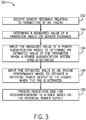
- FIG. 3 is a flow chart of an embodiment of a computer-implemented method 150 for determining a potential value of the power output of an engine (e.g., the engine 14 or the gas turbine 82) if a power augmentation system 16 (e.g., a cooler, an oxidant cooler, the evaporative cooler 94, the chiller 96, the water supply 98, the compressor 100, the fuel supply 102, and/or the steam supply 104) is activated to augment the power output of the engine.
- a power augmentation system 16 e.g., a cooler, an oxidant cooler, the evaporative cooler 94, the chiller 96, the water supply 98, the compressor 100, the fuel supply 102, and/or the steam supply 104
- One or more steps or all steps of the method 150 may be executed by the controller 12.
- the method 150 may include receiving (block 152) sensor feedback relating to one or more operating parameters (e.g., input and/or output operating parameters) of the engine.
- the controller 12 may receive the engine sensor feedback 38, the ambient sensor feedback 40, and/or the power augmentation sensor feedback 42 from the sensors 110. Additionally, the method 150 may include determining (block 154) a measured value of at least one input operating parameter of the engine based on the sensor feedback. For example, in some embodiments, the controller 12 may determine the temperature, pressure, relative humidity, density, and/or composition of the oxidant 18 routed to the engine.
- the method 150 may include inputting (block 156) the measured value of the at least one input operating parameter in a power augmentation model 44 for the power augmentation system 16 to determine an estimated value of the at least one operating parameter caused by activation of the power augmentation system 16. Additionally, the method 150 may include inputting (block 158) the estimated value of the at least one input operating parameter in an engine performance model 48 to determine a potential value of the power output of the engine caused by activation of the power augmentation system 16. As discussed above, in some embodiments, the controller 12 may also input measured values of other input operating parameters and/or estimated values of other input operating parameters in the engine performance model 48 to the determine the potential value of the power output. Additionally, as discussed above, the controller 12 may input a performance metric for the engine in the engine performance model 48 to determine the potential value of the power output.
- the method 150 may include providing (block 160) one or more user-perceivable indications (e.g., visual indications) and/or recommendations based on the potential value of the power output of the engine.
- the controller 12 may cause the input/output device 50 to display a numeric value and/or a graphical indication of the potential value of the power output.
- the controller 12 may cause the input/output device 50 to display recommendations based on a comparison of the potential value of the power output to a threshold.
- the controller 12 may cause the input/output device 50 to display a recommendation to activate the power augmentation system 16 if the potential value is above a predetermined threshold and/or a recommendation to keep the power augmentation system 16 deactivated if the potential value is below the predetermined threshold.
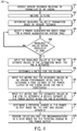
- FIG. 4 is a flow chart of an embodiment of a computer-implemented method 180 for determining a potential change in the power output of an engine (e.g., the engine 14 or the gas turbine 82) caused by activation of a power augmentation system 16 (e.g., the evaporative cooler 94, the chiller 96, the water supply 98, the compressor 100, the fuel supply 102, and/or the steam supply 104) used to augment the power output of the engine.
- a power augmentation system 16 e.g., the evaporative cooler 94, the chiller 96, the water supply 98, the compressor 100, the fuel supply 102, and/or the steam supply 104
- One or more steps or all steps of the method 180 may be executed by the controller 12.
- the method 180 may include receiving (block 152) sensor feedback relating to one or more operating parameters (e.g., input and/or output operating parameters) of the engine.
- the method 180 may include discarding (block 182) outliers in the sensor feedback and/or data in the sensor feedback that is determined to be incomplete or erroneous. Further, the method 180 may include determining (block 184) measured values of one or more input operating parameters of the engine based on the sensor feedback.
- the method 180 may include selecting (block 186) a power augmentation model 44 for the power augmentation system 16.
- the memory 34 and/or the database 46 may store different power augmentation models 44 for the same component of the power augmentation system 16 (e.g., the evaporative cooler 94, the chiller 96, the water supply 98, etc.) that use different input operating parameters and/or that output different input operating parameters.
- the memory 34 and/or the database 46 may store a temperature drop model (e.g., temperature reduction model) for the evaporative cooler 94 that is configured to estimate a potential value of the temperature of the oxidant 18 (e.g., ambient air) based on a measured value of the temperature of the oxidant 18, and the memory 34 and/or the database 46 may store a saturation efficiency model for the evaporative cooler 94 that is configured to estimate a potential value of the temperature of the oxidant 18 based on measured values of the temperature and relative humidity of the oxidant 18.
- a temperature drop model e.g., temperature reduction model
- the evaporative cooler 94 may store a saturation efficiency model for the evaporative cooler 94 that is configured to estimate a potential value of the temperature of the oxidant 18 based on measured values of the temperature and relative humidity of the oxidant 18.
- the controller 12 may select a power augmentation model 44 from a plurality of power augmentation models 44 based on the available measured input operating parameters and the input operating parameters used by the power augmentation models 44. For example, a power augmentation model 44 may not be suitable for use if the measured value of an input operating parameter used in the power augmentation model 44 is unknown.
- each power augmentation model 44 may be associated with a performance metric indicative of the accuracy of the power augmentation model 44, and the controller 12 may select a power augmentation model 44 based on the performance metrics for the performance augmentation models 44. For example, the controller 12 may select the power augmentation model 44 with the highest performance metric provided that the power augmentation model 44 is appropriate based on the available measured input operating parameters. In some embodiments, the controller 12 may select a power augmentation model 44 based on user input via the input/output device 50.
- the method 180 may include determining (query 188) whether the measured values of the one or more input operating parameters are inside the envolvent of the power augmentation model 44.
- the power augmentation model 44 may be trained using a plurality of measured values of the one or more input operating parameters.
- the envolvent of the power augmentation model 44 includes a range of measured values of the one or more input operating parameters that are appropriate for use with the power augmentation model 44 based on the training of the power augmentation model 44.
- the power augmentation model 44 has been proven to work (e.g., provide an accurate estimated value) with the measured value based on the training of the power augmentation model 44, then the measured value falls inside of the envolvent of the power augmentation model 44. Conversely, if the power augmentation model 44 has not been proven to work with the measured value based on the training, then the measured value falls outside of the envolvent of the power augmentation model 44.
- the method 180 may include selecting (block 186) a different power augmentation model 44. Additionally or alternatively, the controller 12 may continue to receive (block 182) sensor feedback and determine (block 184) measured values of the input operating parameters until the measured values are determined to fall inside of the envolvent of a selected power augmentation model 44. If the measured values fall inside of the envolvent, the method 180 may include inputting (block 190) the measured values of the one or more input operating parameters in the power augmentation model 44 to determine estimated values of the one or more input operating parameters that may occur if the power augmentation system 16 is activated.
- the power augmentation model 44 may estimate the potential value of the temperature of the oxidant 18 if the power augmentation system 16 is activated based on the measured value (e.g., a real-time or substantially real time value) of the temperature of the oxidant 18.
- the method 180 may include determining (block 192) a performance metric for the engine.
- the performance metric may be stored in the memory 34 of the controller 12, downloaded from the database 46, and/or inputted by a user using the input/output device 50.
- the controller 12 may determine the performance metric based on the sensor feedback, as discussed below in FIG. 5 .
- the method 180 may include inputting (block 194) the performance metric and the measured values of the input operating parameters in an engine performance model 48 to determine a first estimate of the power output of the engine when the power augmentation system 16 is deactivated.
- the method 180 may include inputting (block 196) the performance metric and the estimated values of the input operating parameters in the engine performance model 48 to determine a second estimate of the power output of the engine when the power augmentation system 16 is activated. Further, the method 180 may include determining (block 198) a potential change in the power output of the engine caused by activation of the power augmentation system 16 based on the difference between the first estimate and the second estimate.
- the method 180 may include providing (block 200) one or more user-perceivable indications (e.g., visual indications) and/or recommendations based on the potential change in the power output of the engine caused by activation of the power augmentation system 16.
- the controller 12 may cause the input/output device 50 to display a numeric value and/or a graphical indication of the potential change in the power output.
- the controller 12 may cause the input/output device 50 to display recommendations based on a comparison of the potential change in the power output to a threshold.
- the controller 12 may cause the input/output device 50 to display a recommendation to activate the power augmentation system 16 if the potential change is above a predetermined threshold and/or a recommendation to keep the power augmentation system 16 deactivated if the potential change is below the predetermined threshold.
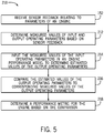
- FIG. 5 is a flow chart of an embodiment of a computer-implemented method 210 for determining a performance metric of an engine (e.g., the engine 14 or the gas turbine 82).
- One or more steps or all steps of the method 210 may be executed by the controller 12.
- the method 210 may include receiving (block 152) sensor feedback relating to one or more operating parameters (e.g., input and/or output operating parameters) of the engine. Additionally, the method 210 includes determining (block 212) measured values of one or more input operating parameters and one or more output operating parameters of the engine based on the sensor feedback.
- the method 210 includes inputting (block 214) the measured values of the one or more input operating parameters in an engine performance model 48 to determine one or more estimated values of one or more output operating parameters of the engine. Additionally, the method 210 includes comparing (block 216) the estimated values of the one or more output operating parameters to corresponding measured values of the one or more output operating parameters and determining (block 218) a performance metric of the engine based on the comparison.
- the controller 12 may determine a performance metric for each estimated output operating parameter.
- the controller 12 may determine an overall performance metric for the engine based on the differences between the estimated values and the measured values.
- the one or more performance metrics may be indicative of degradation of the engine, inefficiencies of the engine, and/or an amount of deviation from ideal behavior. Accordingly, the performance metrics may be based on the difference between the estimated value and the measured value (e.g., the extent or magnitude of the deviation from expected or ideal behavior).
- the controller 12 may determine a first performance metric based on a first difference between an estimated value of an output operating parameter and a measured value of the output operating parameter, and the controller 12 may determine a second performance metric based on a second difference between an estimated value of the output operating parameter and a measured value of the output operating parameter.
- the second performance metric may be indicative of a greater amount of degradation of the engine as compared to the first performance metric if the second difference is greater than the first difference.
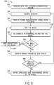
- FIG. 6 is a flow chart of an embodiment of a computer-implemented method 250 for generating a power augmentation model 44 for a component of a power augmentation system 16 (e.g., the evaporative cooler 94, the chiller 96, the water supply 98, the compressor 100, the fuel supply 102, or the steam supply 104).
- One or more steps or all steps of the method 250 may be executed by the controller 12.
- the method 250 may include acquiring (block 252) data (e.g., historical data) for the component of the power augmentation system 16.
- the data may include measured input values (e.g., historical values) of parameters of the component and corresponding measured output values (e.g., historical values) of parameters of the component that resulted from the measured input values.
- the measured input values may include measured values of the temperature, relative humidity, pressure, density, and/or composition of the oxidant 18 entering the evaporative cooler 94
- the measured output values may include measured values of the temperature, relative humidity, pressure, density, and/or composition of the oxidant 18 exiting the evaporative cooler 94.
- the method 250 may include discarding (block 254) outliers and/or incomplete data.
- the method 250 may include training (block 256) the power augmentation model 44 using the data.
- training (block 256) the power augmentation model 44 may include identifying predictive patterns and/or relationships between the input values and the output values.
- the training may identify a predictive relationship between particular input values of ambient temperature and ambient humidity and particular output values of the oxidant 18 temperature, which may be used to predict the temperature of the oxidant 18 exiting the evaporative cooler 94 for particular values of the ambient temperature and humidity.
- the method 250 may include testing (block 258) the power augmentation model 44 and determining (block 260) a performance metric for the power augmentation model 44 based on the testing.
- the performance metric may be indicative of the accuracy of the power augmentation model 44.
- the method 250 may include determining (query 262) whether the power augmentation model 44 is valid based on the performance metric, the number of testing iterations, and/or the variation of assumptions of the power augmentation model 44. If the power augmentation model 44 is determined to be invalid, the method 250 may include varying (block 264) assumptions of the power augmentation model 44 and testing (block 258) the power augmentation model 44 using the varied assumptions. If the power augmentation model 44 is determined to be valid, the method 250 may include identifying (block 266) data points (e.g., measured values) that are poorly predicted by the power augmentation model 44 and determining (query 268) whether the power augmentation model 44 should be updated based on the percentage of poorly predicted data points.
- data points e.g., measured values
- the method 250 may include discarding (block 254) the poorly predicted data points and training (block 256) the power augmentation model 44 using the updated data set. If the power augmentation model 44 does not need to be upgraded, the method 250 may include reporting (block 270) the envolvent and the performance metric of the power augmentation model 44.
- inventions may include estimating (e.g., via a processor-based controller) a potential change in the power output of an engine caused by activation of a power augmentation system.
- the disclosed embodiments illustrate the controller 12 that may use a power augmentation model 44 with a measured value of at least one input operating parameter of an engine (e.g., the engine 14, the gas turbine 82, etc.) to estimate a potential value of the at least one input operating parameter caused by activation of the power augmentation system 16.
- the power augmentation model 44 may be generated and trained using historical data from the specific power augmentation system 16 that is used with the engine.
- the power augmentation model 44 may account for performance characteristics and efficiencies that are specific to the power augmentation system 16, which may increase the accuracy of potential values of operating parameters estimated by the power augmentation model 44. Additionally, the controller 12 may use the estimated values of the input operating parameters in an engine performance model 48 to estimate a potential value of the power output of the engine when the power augmentation system 16 is activated. In some embodiments, the controller 12 may use the potential value of the power output to determine a potential change in the power output caused by activation of the power augmentation system 16.
- the controller 12 may compare the potential value of the power output to a determined or measured value of the power output (e.g., a real-time or substantially real-time value) when the power augmentation system 16 is deactivated and/or may estimate a potential value of the power output when the power augmentation system 16 is deactivated using the engine performance model 48 with measured values of the input operating parameters. Additionally, in some embodiments, the controller 12 may use a performance metric for the engine in the engine performance model 48 to increase the accuracy of parameters estimated using the engine performance model 48, such as the power output. Further, the controller 12 may provide the potential change in the power output and/or recommendations based on the potential change in the power output to a user, which may facilitate the user in determining whether to activate the power augmentation system 16.
- a determined or measured value of the power output e.g., a real-time or substantially real-time value
- the controller 12 may use a performance metric for the engine in the engine performance model 48 to increase the accuracy of parameters estimated using the engine performance model 48, such as the
Landscapes
- Engineering & Computer Science (AREA)
- Chemical & Material Sciences (AREA)
- Combustion & Propulsion (AREA)
- Mechanical Engineering (AREA)
- General Engineering & Computer Science (AREA)
- Physics & Mathematics (AREA)
- Fluid Mechanics (AREA)
- General Physics & Mathematics (AREA)
- Combined Controls Of Internal Combustion Engines (AREA)
- Control Of Turbines (AREA)
Applications Claiming Priority (1)
| Application Number | Priority Date | Filing Date | Title |
|---|---|---|---|
| US15/145,497 US10215665B2 (en) | 2016-05-03 | 2016-05-03 | System and method to model power output of an engine |
Publications (1)
| Publication Number | Publication Date |
|---|---|
| EP3242007A1 true EP3242007A1 (de) | 2017-11-08 |
Family
ID=58638804
Family Applications (1)
| Application Number | Title | Priority Date | Filing Date |
|---|---|---|---|
| EP17168550.6A Withdrawn EP3242007A1 (de) | 2016-05-03 | 2017-04-27 | System und verfahren zur modellierung der leistungsabgabe eines motors |
Country Status (3)
| Country | Link |
|---|---|
| US (1) | US10215665B2 (de) |
| EP (1) | EP3242007A1 (de) |
| JP (1) | JP6878108B2 (de) |
Cited By (1)
| Publication number | Priority date | Publication date | Assignee | Title |
|---|---|---|---|---|
| CN108104954A (zh) * | 2017-12-01 | 2018-06-01 | 中国直升机设计研究所 | 一种涡轴发动机功率状态监控方法 |
Families Citing this family (8)
| Publication number | Priority date | Publication date | Assignee | Title |
|---|---|---|---|---|
| US20170363006A1 (en) * | 2016-06-20 | 2017-12-21 | General Electric Company | System to enable spray intercooling in isochronous operation for power augmentation for spray intercooling engines |
| US11085321B2 (en) * | 2018-01-30 | 2021-08-10 | Honeywell International Inc. | Bleed air compensated continuous power assurance analysis system and method |
| US10961909B2 (en) | 2018-05-15 | 2021-03-30 | General Electric Company | Variable evaporative cooling system |
| CN112469613A (zh) * | 2018-05-16 | 2021-03-09 | 西门子交通奥地利有限责任公司 | 用于对车辆、车辆组件和行车道进行诊断和监控的方法和设备 |
| US11015480B2 (en) * | 2018-08-21 | 2021-05-25 | General Electric Company | Feed forward load sensing for hybrid electric systems |
| US20200200035A1 (en) * | 2018-12-21 | 2020-06-25 | General Electric Company | Methods and systems for monitoring gas turbine startups |
| FR3095475B1 (fr) * | 2019-04-24 | 2021-04-16 | Safran Helicopter Engines | Procédé de régulation de turbomachine comprenant un dispositif d’augmentation temporaire de puissance |
| US11668239B2 (en) | 2020-06-24 | 2023-06-06 | General Electric Company | System and method for controlling temperature in an air intake |
Citations (5)
| Publication number | Priority date | Publication date | Assignee | Title |
|---|---|---|---|---|
| DE19963358A1 (de) * | 1999-12-28 | 2001-07-12 | Bosch Gmbh Robert | Verfahren und Vorrichtung zur Steuerung einer Brennkraftmaschine mit einem Luftsystem |
| US20120072194A1 (en) * | 2010-09-20 | 2012-03-22 | General Electric Company | Methods and Systems for Modeling Turbine Operation |
| EP2549415A1 (de) * | 2011-07-22 | 2013-01-23 | General Electric Company | Vorhersage der Verschlechterung von Gasturbinen auf Basis eines personalisierten Models |
| EP2789837A1 (de) * | 2011-12-07 | 2014-10-15 | Toyota Jidosha Kabushiki Kaisha | Steuerungsvorrichtung für einen vorbrennungsmotor mit einem superlader |
| US20150275786A1 (en) * | 2014-03-26 | 2015-10-01 | GM Global Technology Operations LLC | Non-model predictive control to model predictive control transitions |
Family Cites Families (13)
| Publication number | Priority date | Publication date | Assignee | Title |
|---|---|---|---|---|
| US4766553A (en) | 1984-03-23 | 1988-08-23 | Azmi Kaya | Heat exchanger performance monitor |
| EP1217473A1 (de) | 2000-12-21 | 2002-06-26 | Abb Research Ltd. | Verfahren zur Optimierung von Regelungsparametern in einer Kraftwerkanlage |
| US20040102872A1 (en) | 2002-11-26 | 2004-05-27 | Schick Louis Andrew | Method and tool for power plant operational optimization |
| US7275377B2 (en) | 2004-08-11 | 2007-10-02 | Lawrence Kates | Method and apparatus for monitoring refrigerant-cycle systems |
| US8082736B2 (en) * | 2006-01-04 | 2011-12-27 | Cummins Inc. | Temperature determination technique for a turbocharger |
| CN101517506B (zh) | 2006-07-17 | 2011-11-30 | 欣达公司 | 计算和预测发电机组的性能 |
| JP4948348B2 (ja) * | 2007-10-02 | 2012-06-06 | 株式会社日立製作所 | コンバインドサイクル発電プラント |
| US8437880B2 (en) | 2010-05-17 | 2013-05-07 | General Electric Company | System and method for enhancement of power generation facilities |
| WO2012024692A2 (en) | 2010-08-20 | 2012-02-23 | Federspiel Clifford C | Energy-optimal control decisions for hvac systems |
| JP5427196B2 (ja) * | 2011-02-01 | 2014-02-26 | 株式会社日立製作所 | 発電プラント、発電プラントにおける吸気冷却制御装置及び発電プラントの運転制御方法 |
| US8452515B2 (en) | 2011-09-15 | 2013-05-28 | General Electric Company | System and method for simulating a gas turbine compressor |
| US20130151022A1 (en) | 2011-12-07 | 2013-06-13 | General Electric Company | Systems and Methods for Assessing Future Power Plant Capabilities |
| US9002530B2 (en) | 2012-04-23 | 2015-04-07 | General Electric Company | Power plant operation enhancement |
-
2016
- 2016-05-03 US US15/145,497 patent/US10215665B2/en active Active
-
2017
- 2017-04-19 JP JP2017082455A patent/JP6878108B2/ja active Active
- 2017-04-27 EP EP17168550.6A patent/EP3242007A1/de not_active Withdrawn
Patent Citations (5)
| Publication number | Priority date | Publication date | Assignee | Title |
|---|---|---|---|---|
| DE19963358A1 (de) * | 1999-12-28 | 2001-07-12 | Bosch Gmbh Robert | Verfahren und Vorrichtung zur Steuerung einer Brennkraftmaschine mit einem Luftsystem |
| US20120072194A1 (en) * | 2010-09-20 | 2012-03-22 | General Electric Company | Methods and Systems for Modeling Turbine Operation |
| EP2549415A1 (de) * | 2011-07-22 | 2013-01-23 | General Electric Company | Vorhersage der Verschlechterung von Gasturbinen auf Basis eines personalisierten Models |
| EP2789837A1 (de) * | 2011-12-07 | 2014-10-15 | Toyota Jidosha Kabushiki Kaisha | Steuerungsvorrichtung für einen vorbrennungsmotor mit einem superlader |
| US20150275786A1 (en) * | 2014-03-26 | 2015-10-01 | GM Global Technology Operations LLC | Non-model predictive control to model predictive control transitions |
Cited By (1)
| Publication number | Priority date | Publication date | Assignee | Title |
|---|---|---|---|---|
| CN108104954A (zh) * | 2017-12-01 | 2018-06-01 | 中国直升机设计研究所 | 一种涡轴发动机功率状态监控方法 |
Also Published As
| Publication number | Publication date |
|---|---|
| JP2017201166A (ja) | 2017-11-09 |
| US10215665B2 (en) | 2019-02-26 |
| JP6878108B2 (ja) | 2021-05-26 |
| US20170322116A1 (en) | 2017-11-09 |
Similar Documents
| Publication | Publication Date | Title |
|---|---|---|
| US10215665B2 (en) | System and method to model power output of an engine | |
| JP7314323B2 (ja) | コンバインド・サイクル・ガス・タービン運転の最適化のための方法及びシステム | |
| Asgari et al. | Modelling and simulation of gas turbines | |
| US10732595B2 (en) | Control parameter automatic-adjustment apparatus, control parameter automatic-adjustment method, and control parameter automatic-adjustment apparatus network | |
| CN106404403B (zh) | 用于涡轮机的分析的方法和系统 | |
| JP6877908B2 (ja) | 排気ガスへの冷却剤供給を制御するためのシステム | |
| US10401847B2 (en) | System and method for issue detection of industrial processes | |
| CN107448299B (zh) | 确定过滤器壳体的状态的计算装置、方法和计算机可读介质 | |
| EP3296825B1 (de) | Intelligentes flüssigkraftstoffsystem mit fähigkeit zur selbstdiagnose | |
| CN101595288A (zh) | 监测内燃机过程状态的方法和系统 | |
| Asgari | Modelling, simulation and control of gas turbines using artificial neural networks | |
| US11248536B2 (en) | Systems and methods for flame holding avoidance in gas turbine combustors | |
| US20180307997A1 (en) | Systems and methods for improved quantification of uncertainty in turbomachinery | |
| EP3239614A1 (de) | Systeme und verfahren zur vorhersage physikalischer parameter für ein kraftstoffsystem | |
| Kim | Prediction-focused machine learning for performance adaptation of aero gas turbines through steady-state and transient simulation | |
| JP6032847B2 (ja) | 蒸気タービン起動制御システム | |
| Asgari et al. | Considerations in modelling and control of gas turbines—A review | |
| JP2018168855A (ja) | 発電プラントの始動時間を予測し強化するためのシステムおよび方法 | |
| US20180313224A1 (en) | Method and system for improved design and implementation of turbomachinery | |
| US20240191663A1 (en) | Prediction emission monitoring | |
| Al-Kloub | Mathematical Modeling and Parameters Identification of a Large-Scale Gas Turbine Using Meta-Heuristic Optimization Techniques | |
| JP2025538354A (ja) | 流体注入を考慮したガスタービンシステムのモデルベースの制御のためのシステムおよび方法 | |
| Sampath et al. | Managing Maintenance and Operational Availability of Gas Turbine Propelled Naval Ships Through Advanced Engine Fault Diagnostics | |
| Loboda | Development and Evaluation of Algorithms for Gas Turbine Condition Monitoring and Diagnostics | |
| Bhatt | Economic Dispatch of the Combined Cycle Power Plant Using Machine Learning |
Legal Events
| Date | Code | Title | Description |
|---|---|---|---|
| PUAI | Public reference made under article 153(3) epc to a published international application that has entered the european phase |
Free format text: ORIGINAL CODE: 0009012 |
|
| STAA | Information on the status of an ep patent application or granted ep patent |
Free format text: STATUS: THE APPLICATION HAS BEEN PUBLISHED |
|
| AK | Designated contracting states |
Kind code of ref document: A1 Designated state(s): AL AT BE BG CH CY CZ DE DK EE ES FI FR GB GR HR HU IE IS IT LI LT LU LV MC MK MT NL NO PL PT RO RS SE SI SK SM TR |
|
| AX | Request for extension of the european patent |
Extension state: BA ME |
|
| STAA | Information on the status of an ep patent application or granted ep patent |
Free format text: STATUS: REQUEST FOR EXAMINATION WAS MADE |
|
| 17P | Request for examination filed |
Effective date: 20180508 |
|
| RBV | Designated contracting states (corrected) |
Designated state(s): AL AT BE BG CH CY CZ DE DK EE ES FI FR GB GR HR HU IE IS IT LI LT LU LV MC MK MT NL NO PL PT RO RS SE SI SK SM TR |
|
| GRAP | Despatch of communication of intention to grant a patent |
Free format text: ORIGINAL CODE: EPIDOSNIGR1 |
|
| STAA | Information on the status of an ep patent application or granted ep patent |
Free format text: STATUS: GRANT OF PATENT IS INTENDED |
|
| INTG | Intention to grant announced |
Effective date: 20190204 |
|
| STAA | Information on the status of an ep patent application or granted ep patent |
Free format text: STATUS: THE APPLICATION IS DEEMED TO BE WITHDRAWN |
|
| 18D | Application deemed to be withdrawn |
Effective date: 20190615 |