EP3241522B1 - Method for dental implant planning, apparatus for same, and recording medium having same recorded thereon - Google Patents
Method for dental implant planning, apparatus for same, and recording medium having same recorded thereon Download PDFInfo
- Publication number
- EP3241522B1 EP3241522B1 EP15875548.8A EP15875548A EP3241522B1 EP 3241522 B1 EP3241522 B1 EP 3241522B1 EP 15875548 A EP15875548 A EP 15875548A EP 3241522 B1 EP3241522 B1 EP 3241522B1
- Authority
- EP
- European Patent Office
- Prior art keywords
- implant
- objects
- virtual crown
- treatment planning
- dental implant
- Prior art date
- Legal status (The legal status is an assumption and is not a legal conclusion. Google has not performed a legal analysis and makes no representation as to the accuracy of the status listed.)
- Active
Links
Images


Classifications
-
- G—PHYSICS
- G16—INFORMATION AND COMMUNICATION TECHNOLOGY [ICT] SPECIALLY ADAPTED FOR SPECIFIC APPLICATION FIELDS
- G16H—HEALTHCARE INFORMATICS, i.e. INFORMATION AND COMMUNICATION TECHNOLOGY [ICT] SPECIALLY ADAPTED FOR THE HANDLING OR PROCESSING OF MEDICAL OR HEALTHCARE DATA
- G16H50/00—ICT specially adapted for medical diagnosis, medical simulation or medical data mining; ICT specially adapted for detecting, monitoring or modelling epidemics or pandemics
- G16H50/50—ICT specially adapted for medical diagnosis, medical simulation or medical data mining; ICT specially adapted for detecting, monitoring or modelling epidemics or pandemics for simulation or modelling of medical disorders
-
- A—HUMAN NECESSITIES
- A61—MEDICAL OR VETERINARY SCIENCE; HYGIENE
- A61C—DENTISTRY; APPARATUS OR METHODS FOR ORAL OR DENTAL HYGIENE
- A61C13/00—Dental prostheses; Making same
- A61C13/0003—Making bridge-work, inlays, implants or the like
- A61C13/0004—Computer-assisted sizing or machining of dental prostheses
-
- A—HUMAN NECESSITIES
- A61—MEDICAL OR VETERINARY SCIENCE; HYGIENE
- A61C—DENTISTRY; APPARATUS OR METHODS FOR ORAL OR DENTAL HYGIENE
- A61C19/00—Dental auxiliary appliances
- A61C19/04—Measuring instruments specially adapted for dentistry
-
- A—HUMAN NECESSITIES
- A61—MEDICAL OR VETERINARY SCIENCE; HYGIENE
- A61C—DENTISTRY; APPARATUS OR METHODS FOR ORAL OR DENTAL HYGIENE
- A61C8/00—Means to be fixed to the jaw-bone for consolidating natural teeth or for fixing dental prostheses thereon; Dental implants; Implanting tools
-
- G—PHYSICS
- G06—COMPUTING OR CALCULATING; COUNTING
- G06F—ELECTRIC DIGITAL DATA PROCESSING
- G06F30/00—Computer-aided design [CAD]
- G06F30/20—Design optimisation, verification or simulation
Definitions
- the present invention relates to a method of dental implant treatment planning, a device and a recording medium therefore. More specifically, the present invention relates to a technology that reduces complexity and improves accuracy for determining a position of implant objects when planning a dental implant treatment.
- the dental implant treatment goes through an implant treatment planning prior to the treatment to determine appropriate variables of the implant to the patient's bone condition, such as size, type, position, orientation and shape, etc.
- the implant treatment planning acquires images such as X-ray, CT, MRI, panorama, etc. to exam quantity and quality etc. of both jaw and dental bone of a patient through image acquisition equipment, and simulates position, orientation, and form, etc. through a software program by choosing type, size, etc. of the implant which fits the patient's condition.
- the existing software program for dental implant planning is implemented to generate each of objects of the implant such as a fixture, an abutment, a sleeve, a virtual crown and modify position or size of the respective object.
- objects of the implant such as a fixture, an abutment, a sleeve, a virtual crown and modify position or size of the respective object.
- the size of a virtual crown size cannot be modified and although modification function is given, it only provides limited function to increase or decrease the size of the virtual crown in all directions with the same ratio, wherein the virtual crown has the same weight of the size modification in the left and right direction from the center axis of the virtual crown.
- US 2012/070803 discloses methods, systems, computer-readable media, techniques and processes for crown or prosthesis manipulation in dental prosthesis design. These include presenting a 3D model of a multi-tooth prosthesis relative to an area to be reconstructed. An operator may manipulate one or more prosthetic teeth in that 3D model in order to alter the overall shape of the prosthesis.
- the techniques may also include the determination of occlusion with respect to antagonist teeth; of the entire 3D model of the prosthesis and/or of individual 3D models of prosthetic teeth in the model. The position or shape of the 3D model of the prosthesis may be modified based on the occlusion.
- the present invention provides a computer-implemented method of dental implant treatment planning, a computer-readable recording medium having stored thereon the program for the execution of the computer-implemented method of dental treatment planning, and a computer device for dental implant treatment planning, as set out in the appended claims.
- a computer-implemented method of dental implant treatment planning comprises: generating a multi-dimensional image model corresponding to a specific teeth arrangement; placing in the image model implant objects that forms one implant; grouping the implant objects that form the one implant placed in the image model; and moving the position of the grouped implant objects together when one of the implant objects is moved or rotated; wherein the implant objects that form the one implant comprise a virtual crown and a fixture.
- the method may comprise moving the position of the fixture along with the virtual crown if center of the virtual crown changes according to the size modification of the virtual crown when modifying size of the virtual crown
- the method may further comprise identifying natural teeth and occlusal surface corresponding to the teeth arrangement; setting up, down, left and right limit range wherein the objects can be placed on the basis of identification result, wherein the execution of at least one command among position movement, rotation and size modification of the objects is made within the limit range.
- the limit range may be set based on at least one among positions of maximum convexity, neural tube and alveolar bone of tooth which is adjacent to the virtual crown.
- setting up, down, left and right limit range may comprise restricting the up and down movement of the virtual crown by identifying the occlusal surface.
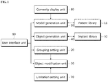
- FIG. 1 is the block diagram of the device for the dental implant treatment planning according to an embodiment of the present invention.
- the device for the dental implant treatment planning according to the present invention comprises a model generation unit 10, a grouping setting unit 20, and an object modification unit 30.
- the model generation unit 10 is to generate a multi-dimensional model about patient's teeth arrangement for the implant treatment planning, and the model for patient's teeth arrangement herein can be either 2D or 3D model.
- the model for patient's teeth arrangement is generated on the basis of an image of patient's jaw or teeth and it also can be generated by matching scan prosthesis or individually digitized prosthesis with anatomical structure in X-ray, MRI, or panorama image.
- the device for the dental implant treatment planning comprises patient's library 11 which the image or model of patient's jaw or teeth is stored in, and a model generation unit 10 that displays the image or a model corresponding to user's selection from the patient's library 11.
- the grouping setting unit 20 is to set or reset the group of the implant objects placed in patient's model, and if multiple objects are set to belong to one group, the multiple objects of the same group are processed as one thing.
- the implant object means all kinds of the object that forms an implant, to comprise a virtual crown, a fixture, an abutment and a sleeve etc..
- the object modification unit 30 is to modify position or size of implant objects, and it moves, rotates, modifies or changes the position of the implant object depending on manipulation command from user.
- the object modification unit 30 modifies either grouped objects together or each object apart according as grouping of the implant objects is set or not.
- the grouping setting unit 30 makes a process of all the objects in the same group as one thing, so that relative position relationship of all the objects in the same group is maintained when moving or rotating the group. Therefore, it is needless to move the respect object and adjust the relative position relation of the implant objects, and also only one manipulation make it possible to modify all the related objects simultaneously, which is very convenient.
- the device for the dental implant treatment planning can comprise an implant library 50, an object generation unit 40, and a user's interface unit 60.
- the implant library 50 stores a variety of implant objects by company, type, size, or length.
- the object generation unit 40 is to generate objects that form an implant.
- the unit 40 can get the objects from the implant library 50 according to the user selection or its selection or import the result of the Wax-up to display the objects in the image.
- the user interface unit 60 is to receive user's commands, and to be implemented with mouse, keyboard, button, keypad, and/or GUI on the screen.
- FIG. 2 illustrates an example of an implementation screen of the device for the implant treatment planning according to an embodiment of the present invention.
- the implementation screen of the device for the implant treatment planning shows the implant object on the model of patient' teeth arrangement.
- the implant object comprises the virtual crown 1, fixture 2 and abutment 3.
- the implant objects are placed in respective position according to user's selection or input.
- the implementation screen of the device for the implant treatment planning in Fig. 2 displays multiple GUI menus, and the most GUI menus illustrate as icons.
- the grouping setting menu about position movement or rotation for a virtual object.
- the implementation screen of the device for the implant treatment planning includes the menu icon 61a to move or rotate a position of the implant object.
- the menu icon 61a is expressed as arrow 61a around the implant object, so the user can move or rotate the implant object by clicking or dragging one end of the icon 61a.
- Fig. 2 depicts the left rotation of the implant object, where the virtual crown 1 is rotated so that the other object such as the fixture 2 etc. in the same group is rotated simultaneously.
- points out the center axis of the virtual crown 1 points out the center axis of the virtual crown 1, and the movement of the center axis has other objects in the same group shift or rotate by the same as the movement of the center axis.
- the center axis lines of implant objects do not need to coincide.
- the center axis lines of implant objects can be misaligned slightly depending the patient's condition, and the implant objects will be moved or rotated with keeping the state of the misalignment of the center axis lines.
- the function of grouping the implant objects can be implemented to work only when moving or rotating specific objects and not to work when moving or rotating the other objects.
- the above implementation example relates to a general procedure for the implant planning to determine the position of the virtual crown 1 and then to determine the position of the other objects.
- the above implementation example has the advantage that users select or handle easily depending on user's decision, because users can choose to modify multiple objects simultaneously or modify just one object by selecting the input icon for the command.
- the device for dental implant treatment planning can comprise the model generation unit 10, the grouping setting unit 20, and the object modification unit 30, and it can further comprise the object generation unit 40, the patient's library 11, the implant library 50 or the limitation setting unit 70.
- the explanation on the same or similar part with the stated embodiment is to be skipped within the overlapping range.
- the device for dental implant treatment planning can perform size modifying function for implant objects.
- size modification for a virtual crown among the implant objects will be described.
- the object modification unit 30 modifies the size of a virtual crown based on the boundary surface of teeth adjacent to a virtual crown.
- the boundary surface for the adjacent tooth includes the boundary surface for maximum convexity of the adjacent tooth crown, and the modification unit 30 should not exceed its boundary surface when modifying size of a virtual crown.
- a size modification command for the virtual crown can be input by dragging or pulling an outline of the virtual crown with mouse control, and the size of virtual crown can be increased or decreased according to the amount of such a user input.
- the implant objects are grouped, if the position of the virtual crown has not been changed, for example, if the center axis has not been changed, the positions of other objects will not be changed.
- the limitation setting unit 70 is to recognize natural teeth and occlusal surface based on image analysis, and to set or reset up, down, left and right limit range where implant objects can be placed.
- the activation or deactivation of limitation setting function can be selected by the user interface unit 60.
- the limitation setting function does not be selected by the user interface unit 60, but remains always activated to limit movement, rotation, modification etc. within the limit range automatically.
- the limit range setting function can be either activated or deactivated by user's selection.
- the object modification unit 30 will do within up, down, left and right limit range when moving position, rotating or modifying size of implant objects.
- the up, down, left and right limit range are set by the position of neural tube, alveolar bone, and maximum convexity of crown of teeth (e.g. natural teeth, artificial teeth or virtual teeth) adjacent to a virtual crown.
- crown of teeth e.g. natural teeth, artificial teeth or virtual teeth
- the object modification unit 30 modifies the objects according to user's command without limits of the movement range when modifying objects.
- FIG. 3 illustrates an example of an implementation screen of the device for the implant treatment planning according to another embodiment of the present invention.
- an implementation screen of the device for the implant treatment planning according to another embodiment of the present invention shows size modification and grouping setting menu for a virtual crown.
- the screen in FIG. 3 shows the size modification or grouping setting function of a virtual crown 1 as an icon.
- the function is activated if clicking the icon, but it is deactivated if clicking the icon once again. Also, to express the activation and deactivation with different colors has users Figure out intuitively whether the function is activated or not.
- an icon 62a which user can adjust the size of the virtual crown 1 with, is generated around the implant objects. Users can increase or decrease it in one or both sides by clicking or dragging the icon in all directions.
- b points out the boundary surface with adjacent teeth, and when the limitation setting function of the limitation setting unit 70 is activated, the expanded virtual crown is limited not to go over the boundary surface.
- the user increased the virtual crown 1 by clicking or operating the icon, and the virtual crown 1 has been increased on the right side of the boundary surface of the adjacent tooth so that, as a result, it can be understood that the center of the virtual crown 1 has been changed.
- FIG. 3 it shows an example that the fixture 2 and the abutment 3 has been moved together according to the movement of the center axis of virtual crown 1.
- the object modification unit 30 recognizes objects as one thing, so if the center axis is moved because the size of a virtual crown is changed, so that relative position relationship of all the objects in the same group is maintained when moving or rotating the group. Therefore, it is needless to move the respect object and adjust the relative position relation of the implant objects, and also only one manipulation make it possible to modify all the related objects simultaneously, which is very convenient.
- a device for the implant treatment planning according to another embodiment of the present invention can comprise a maximum convexity display unit 80.
- the maximum convexity display unit 80 detects a maximum convexity of natural teeth or artificial teeth and displays a maximum convexity of each tooth in 2D or 3D image model.
- the maximum convexity display unit 80 according to the invention keeps and displays a maximum convexity of each tooth crown in a changed slice although the position of slice in 2D or 3D model are changed. Conventionally, if the position of slice changes, the most outer part of teeth in the slice used to be displayed and in this case, when determining the position of an implant object, it should be done to adjust the slice position, checking the image and the properness of the position of the implant objects, which is so inconvenient.
- FIG. 4 illustrates an example of marking a maximum convexity of natural tooth crown or artificial tooth crown in the image model about patient's teeth arrangement, according to an embodiment of the present invention.
- the maximum convexity of each tooth are marked with the yellow line, which is effective to determine a position or select an implant by displaying the maximum convexity of teeth constantly when planning an implant treatment.
- FIG. 5 is a flowchart of a method of the dental implant treatment planning according to an embodiment of the present invention
- FIG. 6 is a flowchart of a method of position movement or rotation of an implant object.
- a method of the dental implant treatment planning generates an image model about patient's teeth arrangement such as 2D or 3D model in step S10, and generates and places in the model the implant objects (e.g. virtual crown, fixture, abutment, etc.) in step S11.
- the implant objects e.g. virtual crown, fixture, abutment, etc.
- a user plans the exact insertion position etc. by adjusting the position and size etc. or the implant object in step S13.
- step S20 if the movement or rotation commands of the implant object are entered by a user in step S20, whether the implant objects are grouped or not is determined in step S21. If the implant objects are grouped, the grouped implant objects are moved or rotated simultaneously in step S23. At this moment, the grouped objects are moved or rotated in the state with relative position of the objects kept.
- step S25 If they are not grouped, the object corresponding to command only is moved or rotated in step S25.
- FIG. 7 is a flowchart of a method of modifying size of an implant object in the dental implant treatment planning according to another embodiment of the present invention.
- natural teeth or occlusal surface are recognized in patient's teeth arrangement in step S30.
- an implant object is generated according to user's selection or input or by the import of the Wax-up in step S31.
- the maximum convexity of each tooth crown can be displayed in the model of teeth arrangement. Although the position of axial slice is changed by user's selection, the maximum convexity of each tooth is displayed constantly. So, it is easy to check whether position determination is proper or not because a user can see the maximum convexity of each tooth intuitively although the slice position is moved.
- step S32 the limit range of up, down, left and right for a virtual crown is set based on the identification result about natural teeth and occlusal surface corresponding to teeth arrangement.
- the limit range of the virtual crown is set by the position of maximum convexity, neural tube and alveolar bone of teeth adjacent to the virtual crown.
- alarm function can be provided to user which is activated when a virtual crown invades in the most outer part of the natural tooth.
- the up or down movement more than predetermined value (e.g. 1mm) from the alveolar bone can be restricted.
- the down movement can be restricted when conflicting with neural tube.
- the up and down movement of a virtual crown is restricted based on identification results of occlusal surface, and the boundary surface of left and right movement of the implant virtual crown is considered as the boundary surface of maximum convexity of natural teeth, artificial teeth and virtual crown.
- the user can intuitively recognize the boundary surface with reference to the modification of the implant, which may increase the accuracy of the object positioning.
- the limit range setting function is set automatically, so it can be applied absolutely when moving, rotating or modifying implant objects, but it also can be activated or deactivated depending on user's selection.
- the function may be activated and deactivated later according as users select the limit range setting function or not.
- the function can be activated by calculating the limit range for implants.
- FIG. 7 illustrates to set the limit range in step S32, but it can be applied in various orders as needed, for example, In FIG. 7 , the order of the steps S31 and S32 can be changed, or S32 can be done at the order between S34 and S35. Referring to FIG.
- an implant modification unit 30 checks whether the limit range setting function is activated or not in step S34, and if the limit range setting function is activated, the virtual crown on either or both sides are increased or decreased within the range in step S35. Meanwhile, if the limit range setting function is deactivated, the size is increased or decreased on horizontal or vertical side or all sides according to command of user's interface unit users without restricting the limit range in step S36.
- step S37 whether the center of maximum convexity for the virtual crown has been moved or not by increasing or decreasing the virtual crown is determined, and if the center of the virtual crown has been moved and objects has been grouped in step S38, other grouped objects are moved together in step S39. However, if the center of the virtual crown has not been moved according to the size modification of the virtual crown, moving other objects is unnecessary.
- FIG. 8 is a flowchart of a method of position movement or rotation of an implant object from the dental implant treatment planning according to another embodiment of the present invention. Overlapping description in the stated embodiment will be skipped for the clarity and simplicity of the explanation.
- step S40 it is done to identify the natural tooth or the occlusal surface in the teeth arrangement of a patient model in step S40. And it generates an object according to the user's selection or input, or import of the implant wax-up in step S41.
- the limit range of the implant object is set based on the maximum convexity, neural tube, and the position of the bone of the adjacent teeth and the virtual crown.
- the up and down movement of a virtual crown is limited based on the identification results of occlusal surface, and the boundary surface of maximum convexity of a virtual crown is considered as a boundary surface of the left and right movement of a virtual crown.
- it increases accuracy of placing implant object because users can recognize the boundary surface intuitively by displaying such a boundary surface in teeth model.
- step S43 If position modification commands of a virtual crown are entered by users in step S43, it checks whether a limit range setting function is activated or not in step S44. If the limit range setting function is activated, it is able to be moved or rotated within a limit range n in step S45, or if the limit range setting function is deactivated, it is able to be moved or rotated freely by user's command in step S46. When moving or rotating the virtual crown, if objects are grouped by checking whether they are grouped or not in step S47, it moves or rotates other grouped objects together in step S48. Otherwise, it modifies the virtual crown alone.
- the screen for teeth implant treatment planning in FIG. 2 and FIG. 3 illustrates as panorama image model, but it may represent four kinds of view - axial, coronal, sagittal, cross-sectional by 3D model, and when modifying an object in one of the screens, it can be implemented applying the modification immediately in other view as well.
- the device for dental implant treatment planning of the invention can be implemented as a device having at least one programmable processor combined with memory device including at least one memory type such as RAM, ROM etc.
- the processor can be used for general or specific uses, the device and method for the dental implant treatment planning according to an embodiment of the present is implemented by digital electrical circuit, computer hardware, firmware, software or those combinations.
- the device can be implemented as a computer program providing the method for implant treatment planning according to the invention when it runs on the computer.
- the computer program is implemented as storage medium containing a computer-readable code to be run by programmable processor. Therefore, the invention is implemented as a computer-readable storage medium containing the computer program that gives command to run the same method for the implant treatment planning as stated when it runs on computer.
Landscapes
- Health & Medical Sciences (AREA)
- Engineering & Computer Science (AREA)
- Public Health (AREA)
- Life Sciences & Earth Sciences (AREA)
- Epidemiology (AREA)
- General Health & Medical Sciences (AREA)
- Dentistry (AREA)
- Animal Behavior & Ethology (AREA)
- Oral & Maxillofacial Surgery (AREA)
- Veterinary Medicine (AREA)
- Biomedical Technology (AREA)
- Theoretical Computer Science (AREA)
- Medical Informatics (AREA)
- Physics & Mathematics (AREA)
- Orthopedic Medicine & Surgery (AREA)
- Biophysics (AREA)
- Evolutionary Computation (AREA)
- Geometry (AREA)
- General Engineering & Computer Science (AREA)
- General Physics & Mathematics (AREA)
- Computer Hardware Design (AREA)
- Data Mining & Analysis (AREA)
- Databases & Information Systems (AREA)
- Pathology (AREA)
- Primary Health Care (AREA)
- Dental Prosthetics (AREA)
- Dental Tools And Instruments Or Auxiliary Dental Instruments (AREA)
Description
- The present invention relates to a method of dental implant treatment planning, a device and a recording medium therefore. More specifically, the present invention relates to a technology that reduces complexity and improves accuracy for determining a position of implant objects when planning a dental implant treatment.
- The dental implant treatment goes through an implant treatment planning prior to the treatment to determine appropriate variables of the implant to the patient's bone condition, such as size, type, position, orientation and shape, etc.
- First of all, the implant treatment planning acquires images such as X-ray, CT, MRI, panorama, etc. to exam quantity and quality etc. of both jaw and dental bone of a patient through image acquisition equipment, and simulates position, orientation, and form, etc. through a software program by choosing type, size, etc. of the implant which fits the patient's condition.
- The existing software program for dental implant planning is implemented to generate each of objects of the implant such as a fixture, an abutment, a sleeve, a virtual crown and modify position or size of the respective object. Like this, not only is it quite cumbersome to generate and modify position or size of the respective object, but also there is a problem that time and efforts are spent a lot due to re-modification of another object which is needed by the modification of the one object.
- Due to these sorts of cumbersomeness and time consuming, a software program for implant treatment planning becomes more inconvenient to users.
- In addition, as a means to evaluate the occlusion, it is to be simulated by generating an object like a virtual crown or using wax-up etc. made by some equipment like a scanner. According to the conventional method of dental implant treatment planning, the size of a virtual crown size cannot be modified and although modification function is given, it only provides limited function to increase or decrease the size of the virtual crown in all directions with the same ratio, wherein the virtual crown has the same weight of the size modification in the left and right direction from the center axis of the virtual crown.
- Due to this, it has been hard to establish the implant treatment plan which reflects the occlusion with natural teeth.
-
US 2012/070803 discloses methods, systems, computer-readable media, techniques and processes for crown or prosthesis manipulation in dental prosthesis design. These include presenting a 3D model of a multi-tooth prosthesis relative to an area to be reconstructed. An operator may manipulate one or more prosthetic teeth in that 3D model in order to alter the overall shape of the prosthesis. In various embodiments, the techniques may also include the determination of occlusion with respect to antagonist teeth; of the entire 3D model of the prosthesis and/or of individual 3D models of prosthetic teeth in the model. The position or shape of the 3D model of the prosthesis may be modified based on the occlusion. - The present invention provides a computer-implemented method of dental implant treatment planning, a computer-readable recording medium having stored thereon the program for the execution of the computer-implemented method of dental treatment planning, and a computer device for dental implant treatment planning, as set out in the appended claims.
- A computer-implemented method of dental implant treatment planning according to one aspect of the present invention comprises: generating a multi-dimensional image model corresponding to a specific teeth arrangement; placing in the image model implant objects that forms one implant; grouping the implant objects that form the one implant placed in the image model; and moving the position of the grouped implant objects together when one of the implant objects is moved or rotated; wherein the implant objects that form the one implant comprise a virtual crown and a fixture.
- The method may comprise moving the position of the fixture along with the virtual crown if center of the virtual crown changes according to the size modification of the virtual crown when modifying size of the virtual crown
- Also, the method may further comprise identifying natural teeth and occlusal surface corresponding to the teeth arrangement; setting up, down, left and right limit range wherein the objects can be placed on the basis of identification result, wherein the execution of at least one command among position movement, rotation and size modification of the objects is made within the limit range.
- In addition, the limit range may be set based on at least one among positions of maximum convexity, neural tube and alveolar bone of tooth which is adjacent to the virtual crown.
- Also, setting up, down, left and right limit range may comprise restricting the up and down movement of the virtual crown by identifying the occlusal surface.
-
-
FIG. 1 is the block diagram of the device for the dental implant treatment planning according to an embodiment of the present invention. -
FIG. 2 illustrates an example of an implementation screen of the device for the implant treatment planning according to an embodiment of the present invention. -
FIG. 3 illustrates an example of an implementation screen of the device for the implant treatment planning according to another embodiment of the present invention. -
FIG. 4 illustrates an example of marking a maximum convexity of natural tooth crown or artificial tooth crown in the image model about patient's teeth arrangement, according to an embodiment of the present invention. -
FIG. 5 is a flowchart for a method of the dental implant treatment planning according to an embodiment of the present invention. -
FIG. 6 is a flowchart of a method of position movement or rotation of an implant object. -
FIG. 7 is a flowchart of a method of modifying size of an implant object in the dental implant treatment planning according to another embodiment of the present invention. -
FIG. 8 is a flowchart of a method of position movement or rotation of an implant object in the dental implant treatment planning according to another embodiment of the present invention. - Hereinafter, exemplary embodiments of the present invention will be described in detail referring to the appended drawings.
-
FIG. 1 is the block diagram of the device for the dental implant treatment planning according to an embodiment of the present invention. Referring toFIG. 1 , the device for the dental implant treatment planning according to the present invention comprises amodel generation unit 10, agrouping setting unit 20, and anobject modification unit 30. - The
model generation unit 10 is to generate a multi-dimensional model about patient's teeth arrangement for the implant treatment planning, and the model for patient's teeth arrangement herein can be either 2D or 3D model. - The model for patient's teeth arrangement is generated on the basis of an image of patient's jaw or teeth and it also can be generated by matching scan prosthesis or individually digitized prosthesis with anatomical structure in X-ray, MRI, or panorama image.
- Referring to
FIG. 1 , the device for the dental implant treatment planning according to another embodiment of the present invention comprises patient'slibrary 11 which the image or model of patient's jaw or teeth is stored in, and amodel generation unit 10 that displays the image or a model corresponding to user's selection from the patient'slibrary 11. - The
grouping setting unit 20 is to set or reset the group of the implant objects placed in patient's model, and if multiple objects are set to belong to one group, the multiple objects of the same group are processed as one thing. - Herein, the implant object means all kinds of the object that forms an implant, to comprise a virtual crown, a fixture, an abutment and a sleeve etc..
- The
object modification unit 30 is to modify position or size of implant objects, and it moves, rotates, modifies or changes the position of the implant object depending on manipulation command from user. Theobject modification unit 30 modifies either grouped objects together or each object apart according as grouping of the implant objects is set or not. - In case objects are grouped, the
grouping setting unit 30 makes a process of all the objects in the same group as one thing, so that relative position relationship of all the objects in the same group is maintained when moving or rotating the group. Therefore, it is needless to move the respect object and adjust the relative position relation of the implant objects, and also only one manipulation make it possible to modify all the related objects simultaneously, which is very convenient. - Referring to
FIG. 1 , the device for the dental implant treatment planning according to another embodiment of the present invention can comprise animplant library 50, anobject generation unit 40, and a user'sinterface unit 60. - The
implant library 50 stores a variety of implant objects by company, type, size, or length. - The
object generation unit 40 is to generate objects that form an implant. Theunit 40 can get the objects from theimplant library 50 according to the user selection or its selection or import the result of the Wax-up to display the objects in the image. - The
user interface unit 60 is to receive user's commands, and to be implemented with mouse, keyboard, button, keypad, and/or GUI on the screen. -
FIG. 2 illustrates an example of an implementation screen of the device for the implant treatment planning according to an embodiment of the present invention. - Referring to
FIG. 2 , the implementation screen of the device for the implant treatment planning shows the implant object on the model of patient' teeth arrangement. - The implant object comprises the
virtual crown 1,fixture 2 andabutment 3. The implant objects are placed in respective position according to user's selection or input. - The implementation screen of the device for the implant treatment planning in
Fig. 2 displays multiple GUI menus, and the most GUI menus illustrate as icons. In the left side of the screen ofFIG. 2 , there is the grouping setting menu about position movement or rotation for a virtual object. - If a user clicks the
grouping setting icon 61 on the screen ofFIG. 2 , then its function is to be activated. And if the user clicks this icon once again, the function is to be deactivated. Activation and deactivation states are displayed with different colors, which makes the user Figure out intuitively whether an implant object is grouped or not. - Also, the implementation screen of the device for the implant treatment planning includes the
menu icon 61a to move or rotate a position of the implant object. InFIG. 2 , themenu icon 61a is expressed asarrow 61a around the implant object, so the user can move or rotate the implant object by clicking or dragging one end of theicon 61a. -
Fig. 2 depicts the left rotation of the implant object, where thevirtual crown 1 is rotated so that the other object such as thefixture 2 etc. in the same group is rotated simultaneously. InFIG. 2 , points out the center axis of thevirtual crown 1, and the movement of the center axis has other objects in the same group shift or rotate by the same as the movement of the center axis. - In this case, the center axis lines of implant objects do not need to coincide. In some cases, the center axis lines of implant objects can be misaligned slightly depending the patient's condition, and the implant objects will be moved or rotated with keeping the state of the misalignment of the center axis lines.
- Meanwhile, the function of grouping the implant objects can be implemented to work only when moving or rotating specific objects and not to work when moving or rotating the other objects.
- For example, if a movement or rotation command of the
virtual crown 1 is input, all the related objects can be moved or rotated simultaneously when the grouping function is activated. On the other hand, if a movement or rotation command of thefixture 2 is input, although the grouping function is activated, only thefixture 2 can be moved or rotated and all the related objects can remain. - The above implementation example relates to a general procedure for the implant planning to determine the position of the
virtual crown 1 and then to determine the position of the other objects. - In another implementation example, it is to be implemented to move or rotate the grouped objects simultaneously only in selection of the menu icon and mover or rotate the respective object in input of the other means, wherein the menu icon selected for moving same grouped objects simultaneously can be displayed when the grouping function is activated.
- The above implementation example has the advantage that users select or handle easily depending on user's decision, because users can choose to modify multiple objects simultaneously or modify just one object by selecting the input icon for the command.
- Meanwhile, the device for dental implant treatment planning according to another embodiment of the present invention will be described by referencing
FIG. 1 andFIG. 3 . - Referring to
FIG. 1 , the device for dental implant treatment planning according to another embodiment of the present invention can comprise themodel generation unit 10, thegrouping setting unit 20, and theobject modification unit 30, and it can further comprise theobject generation unit 40, the patient'slibrary 11, theimplant library 50 or thelimitation setting unit 70. The explanation on the same or similar part with the stated embodiment is to be skipped within the overlapping range. - The device for dental implant treatment planning according to another embodiment of the present invention can perform size modifying function for implant objects. Hereinafter, the example of size modification for a virtual crown among the implant objects will be described.
- When size modification commands of a virtual crown are entered by users, the
object modification unit 30 modifies the size of a virtual crown based on the boundary surface of teeth adjacent to a virtual crown. - Herein, the boundary surface for the adjacent tooth includes the boundary surface for maximum convexity of the adjacent tooth crown, and the
modification unit 30 should not exceed its boundary surface when modifying size of a virtual crown. - For example, a size modification command for the virtual crown can be input by dragging or pulling an outline of the virtual crown with mouse control, and the size of virtual crown can be increased or decreased according to the amount of such a user input.
- At this point, if the implant objects are grouped and the position of the virtual crown are moved by modifying size of the virtual crown, the other objects that belong to the same group with the virtual crown will move together.
- However, although the implant objects are grouped, if the position of the virtual crown has not been changed, for example, if the center axis has not been changed, the positions of other objects will not be changed.
- The
limitation setting unit 70 is to recognize natural teeth and occlusal surface based on image analysis, and to set or reset up, down, left and right limit range where implant objects can be placed. The activation or deactivation of limitation setting function can be selected by theuser interface unit 60. Meanwhile, according to another embodiment of the present invention, the limitation setting function does not be selected by theuser interface unit 60, but remains always activated to limit movement, rotation, modification etc. within the limit range automatically. Hereinafter, an embodiment of the present invention will be described in an example which the limit range setting function can be either activated or deactivated by user's selection. - If the movement range limitation setting function of the
limitation setting unit 70 is activated, theobject modification unit 30 will do within up, down, left and right limit range when moving position, rotating or modifying size of implant objects. - Herein, the up, down, left and right limit range are set by the position of neural tube, alveolar bone, and maximum convexity of crown of teeth (e.g. natural teeth, artificial teeth or virtual teeth) adjacent to a virtual crown.
- If user's modification commands are out of the up, down, left and right limit range, users are informed of this by icon or message displayed on the screen or by sound or voice output.
- For example, when commanded to expand the size of a virtual crown, if size expansion is disabled anymore because the one side edge of the virtual crown expands to boundary surface for the maximum convexity of the adjacent teeth crown, it is executed to expand the other side edge of the virtual crown to the desired size by users. Also, if size expansion is disabled anymore because both of the side edges expand to both adjacent teeth, users are informed of this by displayed icons for the state.
- If the movement range limitation setting function of the
limitation setting unit 70 is deactivated, theobject modification unit 30 modifies the objects according to user's command without limits of the movement range when modifying objects. -
FIG. 3 illustrates an example of an implementation screen of the device for the implant treatment planning according to another embodiment of the present invention. Referring toFIG. 3 , an implementation screen of the device for the implant treatment planning according to another embodiment of the present invention shows size modification and grouping setting menu for a virtual crown. - The screen in
FIG. 3 shows the size modification or grouping setting function of avirtual crown 1 as an icon. The function is activated if clicking the icon, but it is deactivated if clicking the icon once again. Also, to express the activation and deactivation with different colors has users Figure out intuitively whether the function is activated or not. - In
FIG. 3 , when clicking theicon 62, anicon 62a which user can adjust the size of thevirtual crown 1 with, is generated around the implant objects. Users can increase or decrease it in one or both sides by clicking or dragging the icon in all directions. - In
FIG. 3 , b points out the boundary surface with adjacent teeth, and when the limitation setting function of thelimitation setting unit 70 is activated, the expanded virtual crown is limited not to go over the boundary surface. - In
FIG. 3 , the user increased thevirtual crown 1 by clicking or operating the icon, and thevirtual crown 1 has been increased on the right side of the boundary surface of the adjacent tooth so that, as a result, it can be understood that the center of thevirtual crown 1 has been changed. - At this point, if the implant objects are grouped, the other objects are to be moved together with the center axis of the virtual crown moved. In
FIG. 3 , it shows an example that thefixture 2 and theabutment 3 has been moved together according to the movement of the center axis ofvirtual crown 1. - In case of setting grouping like this, since the
object modification unit 30 recognizes objects as one thing, so if the center axis is moved because the size of a virtual crown is changed, so that relative position relationship of all the objects in the same group is maintained when moving or rotating the group. Therefore, it is needless to move the respect object and adjust the relative position relation of the implant objects, and also only one manipulation make it possible to modify all the related objects simultaneously, which is very convenient. - Meanwhile, a device for the implant treatment planning according to another embodiment of the present invention can comprise a maximum
convexity display unit 80. - The maximum
convexity display unit 80 detects a maximum convexity of natural teeth or artificial teeth and displays a maximum convexity of each tooth in 2D or 3D image model. The maximumconvexity display unit 80 according to the invention keeps and displays a maximum convexity of each tooth crown in a changed slice although the position of slice in 2D or 3D model are changed. Conventionally, if the position of slice changes, the most outer part of teeth in the slice used to be displayed and in this case, when determining the position of an implant object, it should be done to adjust the slice position, checking the image and the properness of the position of the implant objects, which is so inconvenient. - Otherwise, in the present invention, although the position of the slice is changed in 2D or 3D model, the maximum convexity of the tooth is displayed constantly. So, it is convenient that users can check intuitionally whether the position is adjusted well or not, without checking or adjusting a position of a slice again.
FIG. 4 illustrates an example of marking a maximum convexity of natural tooth crown or artificial tooth crown in the image model about patient's teeth arrangement, according to an embodiment of the present invention. Referring toFIG. 4 , the maximum convexity of each tooth are marked with the yellow line, which is effective to determine a position or select an implant by displaying the maximum convexity of teeth constantly when planning an implant treatment. - For example, although users move the slice position of teeth model, not the most outer part of each tooth in the slice, but the maximum convexity of each tooth is displayed by remaining it, so users can check whether the position adjustment of the implant object is proper or not without changing the slice.
- Hereinafter, a method of the dental implant treatment planning according to another embodiment of the present invention will be described.
FIG. 5 is a flowchart of a method of the dental implant treatment planning according to an embodiment of the present invention, andFIG. 6 is a flowchart of a method of position movement or rotation of an implant object. - Referring to
FIG. 5 , a method of the dental implant treatment planning according to another embodiment of the present invention generates an image model about patient's teeth arrangement such as 2D or 3D model in step S10, and generates and places in the model the implant objects (e.g. virtual crown, fixture, abutment, etc.) in step S11. A user plans the exact insertion position etc. by adjusting the position and size etc. or the implant object in step S13. - Referring to
FIG. 6 , if the movement or rotation commands of the implant object are entered by a user in step S20, whether the implant objects are grouped or not is determined in step S21. If the implant objects are grouped, the grouped implant objects are moved or rotated simultaneously in step S23. At this moment, the grouped objects are moved or rotated in the state with relative position of the objects kept. - If they are not grouped, the object corresponding to command only is moved or rotated in step S25.
-
FIG. 7 is a flowchart of a method of modifying size of an implant object in the dental implant treatment planning according to another embodiment of the present invention. - Referring to
FIG. 7 , natural teeth or occlusal surface are recognized in patient's teeth arrangement in step S30. And an implant object is generated according to user's selection or input or by the import of the Wax-up in step S31. Herein, the maximum convexity of each tooth crown can be displayed in the model of teeth arrangement. Although the position of axial slice is changed by user's selection, the maximum convexity of each tooth is displayed constantly. So, it is easy to check whether position determination is proper or not because a user can see the maximum convexity of each tooth intuitively although the slice position is moved. - Meanwhile, in step S32, the limit range of up, down, left and right for a virtual crown is set based on the identification result about natural teeth and occlusal surface corresponding to teeth arrangement. The limit range of the virtual crown is set by the position of maximum convexity, neural tube and alveolar bone of teeth adjacent to the virtual crown.
- For example, alarm function can be provided to user which is activated when a virtual crown invades in the most outer part of the natural tooth. To prevent invading alveolar bone, the up or down movement more than predetermined value (e.g. 1mm) from the alveolar bone can be restricted. Also, the down movement can be restricted when conflicting with neural tube.
- For example, the up and down movement of a virtual crown is restricted based on identification results of occlusal surface, and the boundary surface of left and right movement of the implant virtual crown is considered as the boundary surface of maximum convexity of natural teeth, artificial teeth and virtual crown. In addition, by displaying such a boundary surface on the tooth model, the user can intuitively recognize the boundary surface with reference to the modification of the implant, which may increase the accuracy of the object positioning.
- As stated above, the limit range setting function is set automatically, so it can be applied absolutely when moving, rotating or modifying implant objects, but it also can be activated or deactivated depending on user's selection.
- If the above limit range setting function is activated or deactivated by user's selection, after calculating the data about the limit range - the up, down, left and right limits - when creating or placing an implant object, the function may be activated and deactivated later according as users select the limit range setting function or not. In the other examples, after users selecting the limit range setting function, then the function can be activated by calculating the limit range for implants. Thus,
FIG. 7 illustrates to set the limit range in step S32, but it can be applied in various orders as needed, for example, InFIG. 7 , the order of the steps S31 and S32 can be changed, or S32 can be done at the order between S34 and S35. Referring toFIG. 7 again, if a size modification command for a virtual crown is entered by users in step S33, then animplant modification unit 30 checks whether the limit range setting function is activated or not in step S34, and if the limit range setting function is activated, the virtual crown on either or both sides are increased or decreased within the range in step S35. Meanwhile, if the limit range setting function is deactivated, the size is increased or decreased on horizontal or vertical side or all sides according to command of user's interface unit users without restricting the limit range in step S36. - In step S37, whether the center of maximum convexity for the virtual crown has been moved or not by increasing or decreasing the virtual crown is determined, and if the center of the virtual crown has been moved and objects has been grouped in step S38, other grouped objects are moved together in step S39. However, if the center of the virtual crown has not been moved according to the size modification of the virtual crown, moving other objects is unnecessary.
- In
FIG. 8 is a flowchart of a method of position movement or rotation of an implant object from the dental implant treatment planning according to another embodiment of the present invention. Overlapping description in the stated embodiment will be skipped for the clarity and simplicity of the explanation. - Referring to
FIG. 8 , it is done to identify the natural tooth or the occlusal surface in the teeth arrangement of a patient model in step S40. And it generates an object according to the user's selection or input, or import of the implant wax-up in step S41. - At this time, it sets the limit range of the movement up, down, left, and right of the implant object on the basis of the natural teeth or occlusal identification result in step S42. The limit range of the implant object is set based on the maximum convexity, neural tube, and the position of the bone of the adjacent teeth and the virtual crown.
- For example, the up and down movement of a virtual crown is limited based on the identification results of occlusal surface, and the boundary surface of maximum convexity of a virtual crown is considered as a boundary surface of the left and right movement of a virtual crown. In addition, it increases accuracy of placing implant object because users can recognize the boundary surface intuitively by displaying such a boundary surface in teeth model.
- If position modification commands of a virtual crown are entered by users in step S43, it checks whether a limit range setting function is activated or not in step S44. If the limit range setting function is activated, it is able to be moved or rotated within a limit range n in step S45, or if the limit range setting function is deactivated, it is able to be moved or rotated freely by user's command in step S46. When moving or rotating the virtual crown, if objects are grouped by checking whether they are grouped or not in step S47, it moves or rotates other grouped objects together in step S48. Otherwise, it modifies the virtual crown alone.
- When a limit range setting function is activated, if user gives a command which the implant object is out of the up, down, left and right limit range, outputting message, icon, voice etc. leads to guide for determining the position of the implant within a limit range. Among embodiments of the stated present invention, the screen for teeth implant treatment planning in
FIG. 2 andFIG. 3 illustrates as panorama image model, but it may represent four kinds of view - axial, coronal, sagittal, cross-sectional by 3D model, and when modifying an object in one of the screens, it can be implemented applying the modification immediately in other view as well. - The device for dental implant treatment planning of the invention can be implemented as a device having at least one programmable processor combined with memory device including at least one memory type such as RAM, ROM etc.
- The processor can be used for general or specific uses, the device and method for the dental implant treatment planning according to an embodiment of the present is implemented by digital electrical circuit, computer hardware, firmware, software or those combinations. Also, the device can be implemented as a computer program providing the method for implant treatment planning according to the invention when it runs on the computer. The computer program is implemented as storage medium containing a computer-readable code to be run by programmable processor. Therefore, the invention is implemented as a computer-readable storage medium containing the computer program that gives command to run the same method for the implant treatment planning as stated when it runs on computer.
- Those of ordinary skill in the art will appreciate that various modifications, additions and substitutions will be possible without departing from the scope of the invention as defined in the independent claims. Thus, embodiments described herein are for illustrating but not for limiting the technical scope of the present invention.
Claims (15)
- A computer-implemented method of dental implant treatment planning, comprising the steps of:generating a multi-dimensional image model corresponding to a specific teeth arrangement;placing in the image model implant objects that form one implant;grouping the implant objects that form the one implant placed in the image model; andmoving the position of the grouped implant objects together when one of the implant objects is moved or rotated by user input;characterized in that the implant objects that form the one implant comprise a virtual crown (1) and a fixture (2).
- The computer-implemented method of dental implant treatment planning according to claim 1, comprising the step of moving the position of the fixture (2) along with the virtual crown (1) if center of the virtual crown (1) changes according to the size modification of the virtual crown (1) when modifying size of the virtual crown (1).
- The computer-implemented method of dental implant treatment planning according to claim 2, further comprising the steps of:identifying natural teeth and occlusal surface corresponding to the teeth arrangement; andsetting up, down, left and right limit range where the objects can be placed on the basis of identification result,wherein the execution of at least one command among position movement, rotation and size modification of the objects is made within the limit range.
- The computer implemented method of dental implant treatment planning according to claim 3, wherein the limit range is set based on at least one among positions of maximum convexity, neural tube and alveolar bone of tooth which is adjacent to the virtual crown (1).
- The computer-implemented method of dental implant treatment planning according to claim 3, wherein setting up, down, left and right limit range comprises restricting the up and down movement of the virtual crown (1) by identifying the occlusal surface.
- The computer-implemented method of dental implant treatment planning according to claim 3, wherein the size of the virtual crown (1) is increased or decreased to the at least one direction based on the maximum convexity boundary surface of the tooth which is adjacent to the virtual crown (1) when a command of size modification of the virtual crown (1) is input.
- The computer-implemented method of dental implant treatment planning according to claim 6, further comprising the step of marking the maximum convexity of natural teeth or artificial teeth in the image model.
- A computer-readable recording medium having stored thereon the computer program for the execution of the computer-implemented method of dental implant treatment planning according to one among claim 1 to claim 7.
- A computer device for dental implant treatment planning, comprising means for carrying out the computer implemented method of claim 1, and comprising:a model generation unit (10) configured to generate a multi-dimensional image model corresponding to specific teeth arrangement;a grouping setting unit (20) configured to group implant objects that form one implant placed in the image model; andan object modification unit (30) configured to move the position of the grouped implant objects together when one of the implant objects is moved or rotated;wherein the implant objects that form the one implant comprise a virtual crown (1) and a fixture (2).
- A computer device for dental implant treatment planning according to claim 9,
further comprising a limitation setting unit (70) configured to identify the natural teeth and the occlusal surface corresponding the teeth arrangement and to set up, left and right limit range where the objects can be placed based on the occlusal surface,
wherein the object modification unit (30) changes within the limit range when the objects area moved or rotated. - A computer device for dental implant treatment planning according to claim 9,
wherein the object modification unit (30) is configured to move the position of the fixture (2) along with the virtual crown (1), if a virtual crown (1) and a fixture (2) are grouped and the center of the virtual crown (1) changes due to size modification of the virtual crown (1). - A computer device for dental implant treatment planning according to claim 10,
wherein the object modification unit (30) is configured to increase or decrease the size of the virtual crown (1) toward at least one direction based on the maximum convexity of the teeth adjacent to the virtual crown (1) when a command of size modification of the virtual crown (1) is input. - A computer device for dental implant treatment planning according to claim 10,
wherein the object modification unit (30) is configured to request re-setting of the range outputting at least one signal among message, voice or vibration, if the range of position movement or rotation of the objects is out of the limit range. - A computer device for dental implant treatment planning according to claim 9, comprising;
an implant library (50) that objects that form the implant are stored, and
an object generation unit (40) configured to arrange in model corresponding to the teeth arrangement by generating at least one object or importing wax-up result from the implant library (50). - A computer device for dental implant treatment planning according to claim 9, comprising a convexity display unit (80) configured to detect the maximum convexity of the natural teeth or the virtual teeth by analyzing image about the teeth arrangement and displays the maximum convexity in the image model.
Applications Claiming Priority (3)
| Application Number | Priority Date | Filing Date | Title |
|---|---|---|---|
| KR20140195209 | 2014-12-31 | ||
| KR1020150067951A KR101666982B1 (en) | 2014-12-31 | 2015-05-15 | Dental implant planning method, apparatus and recording medium thereof |
| PCT/KR2015/013260 WO2016108454A1 (en) | 2014-12-31 | 2015-12-04 | Method for dental implant planning, apparatus for same, and recording medium having same recorded thereon |
Publications (3)
| Publication Number | Publication Date |
|---|---|
| EP3241522A1 EP3241522A1 (en) | 2017-11-08 |
| EP3241522A4 EP3241522A4 (en) | 2018-10-03 |
| EP3241522B1 true EP3241522B1 (en) | 2020-05-27 |
Family
ID=56505266
Family Applications (1)
| Application Number | Title | Priority Date | Filing Date |
|---|---|---|---|
| EP15875548.8A Active EP3241522B1 (en) | 2014-12-31 | 2015-12-04 | Method for dental implant planning, apparatus for same, and recording medium having same recorded thereon |
Country Status (4)
| Country | Link |
|---|---|
| US (1) | US11195623B2 (en) |
| EP (1) | EP3241522B1 (en) |
| KR (1) | KR101666982B1 (en) |
| CN (1) | CN107430634B (en) |
Families Citing this family (23)
| Publication number | Priority date | Publication date | Assignee | Title |
|---|---|---|---|---|
| WO2018164306A1 (en) * | 2017-03-06 | 2018-09-13 | 주식회사 디오 | Method for managing patient information and electronic device |
| KR101960476B1 (en) * | 2017-04-28 | 2019-03-20 | 주식회사 코어라인소프트 | System and method of dental implant planning |
| KR101949199B1 (en) * | 2017-06-15 | 2019-04-29 | 오스템임플란트 주식회사 | Dental implant placement planning guide method, apparatus and recording medium thereof |
| KR102082414B1 (en) * | 2017-09-29 | 2020-02-27 | 주식회사 리더스덴탈 | Planning method of installation of healing abutment for implant procedure, Computer program for the same, and Recording medium storing computer program thereof |
| KR102085629B1 (en) * | 2017-12-07 | 2020-03-06 | 이혜주 | Apparatus and method for analyzing structure of teeth and jawbone of patient |
| KR102013298B1 (en) * | 2018-03-08 | 2019-08-23 | 주식회사 디오 | manufacturing method for digital overdenture |
| KR101974636B1 (en) * | 2018-04-18 | 2019-05-03 | 오스템임플란트 주식회사 | Dental implant planning method, apparatus and recording medium thereof |
| KR102057207B1 (en) * | 2018-04-30 | 2019-12-18 | 주식회사 디디에스 | Method for analizing 3d oral model and method for designing virtual prosthetics having the same |
| US20230419631A1 (en) * | 2018-10-30 | 2023-12-28 | Segmentron, LLC | Guided Implant Surgery Planning System and Method |
| EP3649978A1 (en) * | 2018-11-07 | 2020-05-13 | W & H Dentalwerk Bürmoos GmbH | Method for web-based data transfer for a dental or dental surgical treatment or diagnostic system and such treatment or diagnostic system |
| KR102198664B1 (en) * | 2019-01-03 | 2021-01-06 | 오스템임플란트 주식회사 | Method and apparatus for dental implant planning capable of automatic fixture replacement considering a risk factor |
| KR102138920B1 (en) * | 2019-04-25 | 2020-07-28 | 오스템임플란트 주식회사 | Method for displaying undercut in prosthesis design and prosthetic CAD apparatus therefor |
| CN113873947A (en) * | 2019-05-22 | 2021-12-31 | 株式会社迪耀 | Nerve detection method and device |
| KR102067614B1 (en) * | 2019-08-02 | 2020-01-17 | 주식회사 임솔 | Methods, apparatus, and computer plates for planning implant surgery |
| WO2021060582A1 (en) * | 2019-09-26 | 2021-04-01 | 주식회사 임솔 | System, method, and computer program for manufacturing dental implant implantation guide |
| US20220409337A1 (en) * | 2019-09-27 | 2022-12-29 | Pusan National University Industry-University Cooperation Foundation | Method for manufacturing implant shape for minimizing the stress applied to implant by using computer, and method and apparatus for recommending optimal occlusal area for implant by using computer |
| KR102149341B1 (en) * | 2019-09-27 | 2020-08-28 | 부산대학교 산학협력단 | A method of creating implants to minimize stress on implants using computers |
| US11660171B2 (en) | 2019-10-18 | 2023-05-30 | Imsol Corp. | System, method and computer program for producing implant placing guide |
| KR102649559B1 (en) * | 2021-07-30 | 2024-03-20 | 오스템임플란트 주식회사 | Guide design method and guide design device for implant surgery |
| US20240404231A1 (en) * | 2021-10-08 | 2024-12-05 | Medit Corp. | Oral image processing method and data processing device |
| TWI823826B (en) * | 2023-07-19 | 2023-11-21 | 郭芯妤 | Image superposition display system and braces assistive devices |
| KR102944869B1 (en) * | 2023-11-14 | 2026-03-30 | 오스템임플란트 주식회사 | Method for planning implant surgery and apparatus thereof |
| KR102836170B1 (en) * | 2024-08-26 | 2025-07-21 | 주식회사 심미치과기공소 | Method for manufacturing a multi-crown type patient-specific implant |
Family Cites Families (23)
| Publication number | Priority date | Publication date | Assignee | Title |
|---|---|---|---|---|
| US4504230A (en) * | 1983-03-23 | 1985-03-12 | The United States Of America As Represented By The Secretary Of The Navy | Prefabricated dental onlays and method therefor |
| US9421074B2 (en) | 2001-04-13 | 2016-08-23 | Orametrix, Inc. | Unified three dimensional virtual craniofacial and dentition model and uses thereof |
| KR100583183B1 (en) * | 2004-02-19 | 2006-05-25 | 차경석 | How to provide orthodontic data |
| GB0514554D0 (en) * | 2005-07-15 | 2005-08-24 | Materialise Nv | Method for (semi-) automatic dental implant planning |
| US9801697B2 (en) * | 2011-03-18 | 2017-10-31 | Natural Dental Implants Ag | Integrated support device for providing temporary primary stability to dental implants and prosthesis, and related methods |
| WO2008129673A1 (en) * | 2007-04-18 | 2008-10-30 | Kabushiki Kaisha Shofu | Artificial teeth |
| EP2156350A1 (en) * | 2007-05-25 | 2010-02-24 | Nobel Biocare Services AG | Method and system for dental planning |
| JP2011509812A (en) | 2008-01-23 | 2011-03-31 | センサブル テクノロジーズ インコーポレイテッド | Tactile controllable dental modeling system |
| US8092215B2 (en) * | 2008-05-23 | 2012-01-10 | Align Technology, Inc. | Smile designer |
| US8718982B2 (en) * | 2008-09-18 | 2014-05-06 | 3Shape A/S | Tools for customized design of dental restorations |
| WO2010105628A2 (en) * | 2009-03-20 | 2010-09-23 | 3Shape A/S | System and method for effective planning, visualization, and optimization of dental restorations |
| US8662900B2 (en) * | 2009-06-04 | 2014-03-04 | Zimmer Dental Inc. | Dental implant surgical training simulation system |
| US20110119992A1 (en) * | 2009-11-24 | 2011-05-26 | Exxonmobil Research And Engineering Company | Oxidation resistant interstitial metal hydride catalysts and associated processes |
| KR20110074186A (en) | 2009-12-24 | 2011-06-30 | 주식회사 사이버메드 | How to design a prosthesis |
| JP5859986B2 (en) * | 2010-02-25 | 2016-02-16 | 3シェイプ アー/エス | Dynamic virtual articulator |
| US8594820B2 (en) * | 2010-09-17 | 2013-11-26 | Nobel Biocare Services Ag | Prosthesis manipulation in dental prosthesis design |
| KR101799873B1 (en) | 2010-10-01 | 2017-11-22 | 쓰리세이프 에이/에스 | Modeling and manufacturing of dentures |
| US8832019B2 (en) * | 2011-01-31 | 2014-09-09 | Fei Gao | Error simulation for image-guided dental implant treatment planning |
| KR101283572B1 (en) | 2011-05-24 | 2013-07-09 | (주)강원지역대학연합기술지주회사 | Method and apparatus for three-dimensional assessment of the morphologic or volumetric change of the tooth by using three-dimensional reverse engineering technology |
| WO2013053903A1 (en) | 2011-10-12 | 2013-04-18 | 3Shape A/S | Method of globally designing a set of teeth |
| EP2793733A1 (en) | 2011-12-21 | 2014-10-29 | 3Shape A/S | Virtually designing a customized healing abutment |
| TWI548403B (en) * | 2013-03-07 | 2016-09-11 | 國立成功大學 | Implant implant path planning method and system |
| DE112014003898B4 (en) * | 2013-08-26 | 2022-12-22 | James R. Glidewell Dental Ceramics, Inc. | Computer-implemented dental restoration design |
-
2015
- 2015-05-15 KR KR1020150067951A patent/KR101666982B1/en active Active
- 2015-12-04 EP EP15875548.8A patent/EP3241522B1/en active Active
- 2015-12-04 CN CN201580070938.3A patent/CN107430634B/en active Active
- 2015-12-04 US US15/541,204 patent/US11195623B2/en active Active
Non-Patent Citations (1)
| Title |
|---|
| None * |
Also Published As
| Publication number | Publication date |
|---|---|
| EP3241522A4 (en) | 2018-10-03 |
| US11195623B2 (en) | 2021-12-07 |
| EP3241522A1 (en) | 2017-11-08 |
| CN107430634A (en) | 2017-12-01 |
| CN107430634B (en) | 2021-10-22 |
| US20170364659A1 (en) | 2017-12-21 |
| KR20160083787A (en) | 2016-07-12 |
| KR101666982B1 (en) | 2016-10-19 |
Similar Documents
| Publication | Publication Date | Title |
|---|---|---|
| US11195623B2 (en) | Method for dental implant planning, apparatus for same, and recording medium having same recorded thereon | |
| KR101834435B1 (en) | Dental implant planning method, apparatus and recording medium thereof | |
| EP3998037B1 (en) | Implant surgery planning method using automatic placement of implant structure, user interface providing method therefor, and teeth image processing device therefor | |
| KR102232294B1 (en) | Method for displaying multi-bone density for dental implant planning and image processing apparatus thereof | |
| US12427001B2 (en) | Apparatus and method for setting margin line | |
| EP4193960B1 (en) | Method for selecting margin line point, and dental cad device therefor | |
| KR102314891B1 (en) | Implant surgery guide design device and method for providing screen using the same | |
| KR102138920B1 (en) | Method for displaying undercut in prosthesis design and prosthetic CAD apparatus therefor | |
| KR102234425B1 (en) | Method and apparatus for matching medical images | |
| KR20210114223A (en) | Dental implant surgery planning method and device thereof | |
| KR101949201B1 (en) | Dental implant planning method, apparatus and recording medium thereof | |
| TWI754259B (en) | Method and apparatus for detecting of nerve in dental image | |
| KR102197309B1 (en) | A guide design method and apparatus for dental implant surgery using fixture invasion area segmentation for maxillary sinus lifting | |
| KR101190651B1 (en) | Simulating apparatus and Simulating method for drilling operation with image | |
| KR102422534B1 (en) | Implant simulation method and apparatus thereof | |
| EP4238534A1 (en) | Method for determining object area from three-dimensional model, and three-dimensional model processing device | |
| KR102269029B1 (en) | Implant simulation method using manipulator and apparatus thereof | |
| KR102205427B1 (en) | Method and apparatus for correcting nerve position in dental image | |
| KR102418811B1 (en) | Method for picking insertion path setting interface and dental CAD device for same | |
| KR102470822B1 (en) | Method for adjusting fixture and apparatus for establishing implant surgery plan | |
| KR102376933B1 (en) | Method and device for providing one or more images for an object | |
| KR102474298B1 (en) | Method for designing prosthetic model and apparatus thereof | |
| KR20200118327A (en) | Method and apparatus for designing implant surgery guide using drilling simulation |
Legal Events
| Date | Code | Title | Description |
|---|---|---|---|
| STAA | Information on the status of an ep patent application or granted ep patent |
Free format text: STATUS: THE INTERNATIONAL PUBLICATION HAS BEEN MADE |
|
| PUAI | Public reference made under article 153(3) epc to a published international application that has entered the european phase |
Free format text: ORIGINAL CODE: 0009012 |
|
| STAA | Information on the status of an ep patent application or granted ep patent |
Free format text: STATUS: REQUEST FOR EXAMINATION WAS MADE |
|
| 17P | Request for examination filed |
Effective date: 20170728 |
|
| AK | Designated contracting states |
Kind code of ref document: A1 Designated state(s): AL AT BE BG CH CY CZ DE DK EE ES FI FR GB GR HR HU IE IS IT LI LT LU LV MC MK MT NL NO PL PT RO RS SE SI SK SM TR |
|
| AX | Request for extension of the european patent |
Extension state: BA ME |
|
| DAV | Request for validation of the european patent (deleted) | ||
| DAX | Request for extension of the european patent (deleted) | ||
| A4 | Supplementary search report drawn up and despatched |
Effective date: 20180903 |
|
| RIC1 | Information provided on ipc code assigned before grant |
Ipc: A61C 8/00 20060101ALI20180828BHEP Ipc: A61C 19/04 20060101AFI20180828BHEP |
|
| GRAP | Despatch of communication of intention to grant a patent |
Free format text: ORIGINAL CODE: EPIDOSNIGR1 |
|
| STAA | Information on the status of an ep patent application or granted ep patent |
Free format text: STATUS: GRANT OF PATENT IS INTENDED |
|
| INTG | Intention to grant announced |
Effective date: 20191219 |
|
| GRAS | Grant fee paid |
Free format text: ORIGINAL CODE: EPIDOSNIGR3 |
|
| GRAA | (expected) grant |
Free format text: ORIGINAL CODE: 0009210 |
|
| STAA | Information on the status of an ep patent application or granted ep patent |
Free format text: STATUS: THE PATENT HAS BEEN GRANTED |
|
| AK | Designated contracting states |
Kind code of ref document: B1 Designated state(s): AL AT BE BG CH CY CZ DE DK EE ES FI FR GB GR HR HU IE IS IT LI LT LU LV MC MK MT NL NO PL PT RO RS SE SI SK SM TR |
|
| REG | Reference to a national code |
Ref country code: GB Ref legal event code: FG4D |
|
| REG | Reference to a national code |
Ref country code: CH Ref legal event code: NV Representative=s name: SERVOPATENT GMBH, CH Ref country code: CH Ref legal event code: EP |
|
| REG | Reference to a national code |
Ref country code: AT Ref legal event code: REF Ref document number: 1273732 Country of ref document: AT Kind code of ref document: T Effective date: 20200615 Ref country code: CH Ref legal event code: PCOW |
|
| REG | Reference to a national code |
Ref country code: DE Ref legal event code: R096 Ref document number: 602015053584 Country of ref document: DE |
|
| REG | Reference to a national code |
Ref country code: LT Ref legal event code: MG4D |
|
| PG25 | Lapsed in a contracting state [announced via postgrant information from national office to epo] |
Ref country code: GR Free format text: LAPSE BECAUSE OF FAILURE TO SUBMIT A TRANSLATION OF THE DESCRIPTION OR TO PAY THE FEE WITHIN THE PRESCRIBED TIME-LIMIT Effective date: 20200828 Ref country code: NO Free format text: LAPSE BECAUSE OF FAILURE TO SUBMIT A TRANSLATION OF THE DESCRIPTION OR TO PAY THE FEE WITHIN THE PRESCRIBED TIME-LIMIT Effective date: 20200827 Ref country code: SE Free format text: LAPSE BECAUSE OF FAILURE TO SUBMIT A TRANSLATION OF THE DESCRIPTION OR TO PAY THE FEE WITHIN THE PRESCRIBED TIME-LIMIT Effective date: 20200527 Ref country code: LT Free format text: LAPSE BECAUSE OF FAILURE TO SUBMIT A TRANSLATION OF THE DESCRIPTION OR TO PAY THE FEE WITHIN THE PRESCRIBED TIME-LIMIT Effective date: 20200527 Ref country code: PT Free format text: LAPSE BECAUSE OF FAILURE TO SUBMIT A TRANSLATION OF THE DESCRIPTION OR TO PAY THE FEE WITHIN THE PRESCRIBED TIME-LIMIT Effective date: 20200928 Ref country code: FI Free format text: LAPSE BECAUSE OF FAILURE TO SUBMIT A TRANSLATION OF THE DESCRIPTION OR TO PAY THE FEE WITHIN THE PRESCRIBED TIME-LIMIT Effective date: 20200527 Ref country code: IS Free format text: LAPSE BECAUSE OF FAILURE TO SUBMIT A TRANSLATION OF THE DESCRIPTION OR TO PAY THE FEE WITHIN THE PRESCRIBED TIME-LIMIT Effective date: 20200927 |
|
| REG | Reference to a national code |
Ref country code: NL Ref legal event code: MP Effective date: 20200527 |
|
| PG25 | Lapsed in a contracting state [announced via postgrant information from national office to epo] |
Ref country code: LV Free format text: LAPSE BECAUSE OF FAILURE TO SUBMIT A TRANSLATION OF THE DESCRIPTION OR TO PAY THE FEE WITHIN THE PRESCRIBED TIME-LIMIT Effective date: 20200527 Ref country code: HR Free format text: LAPSE BECAUSE OF FAILURE TO SUBMIT A TRANSLATION OF THE DESCRIPTION OR TO PAY THE FEE WITHIN THE PRESCRIBED TIME-LIMIT Effective date: 20200527 Ref country code: BG Free format text: LAPSE BECAUSE OF FAILURE TO SUBMIT A TRANSLATION OF THE DESCRIPTION OR TO PAY THE FEE WITHIN THE PRESCRIBED TIME-LIMIT Effective date: 20200827 Ref country code: RS Free format text: LAPSE BECAUSE OF FAILURE TO SUBMIT A TRANSLATION OF THE DESCRIPTION OR TO PAY THE FEE WITHIN THE PRESCRIBED TIME-LIMIT Effective date: 20200527 |
|
| REG | Reference to a national code |
Ref country code: AT Ref legal event code: MK05 Ref document number: 1273732 Country of ref document: AT Kind code of ref document: T Effective date: 20200527 |
|
| PG25 | Lapsed in a contracting state [announced via postgrant information from national office to epo] |
Ref country code: NL Free format text: LAPSE BECAUSE OF FAILURE TO SUBMIT A TRANSLATION OF THE DESCRIPTION OR TO PAY THE FEE WITHIN THE PRESCRIBED TIME-LIMIT Effective date: 20200527 Ref country code: AL Free format text: LAPSE BECAUSE OF FAILURE TO SUBMIT A TRANSLATION OF THE DESCRIPTION OR TO PAY THE FEE WITHIN THE PRESCRIBED TIME-LIMIT Effective date: 20200527 |
|
| PG25 | Lapsed in a contracting state [announced via postgrant information from national office to epo] |
Ref country code: ES Free format text: LAPSE BECAUSE OF FAILURE TO SUBMIT A TRANSLATION OF THE DESCRIPTION OR TO PAY THE FEE WITHIN THE PRESCRIBED TIME-LIMIT Effective date: 20200527 Ref country code: RO Free format text: LAPSE BECAUSE OF FAILURE TO SUBMIT A TRANSLATION OF THE DESCRIPTION OR TO PAY THE FEE WITHIN THE PRESCRIBED TIME-LIMIT Effective date: 20200527 Ref country code: CZ Free format text: LAPSE BECAUSE OF FAILURE TO SUBMIT A TRANSLATION OF THE DESCRIPTION OR TO PAY THE FEE WITHIN THE PRESCRIBED TIME-LIMIT Effective date: 20200527 Ref country code: IT Free format text: LAPSE BECAUSE OF FAILURE TO SUBMIT A TRANSLATION OF THE DESCRIPTION OR TO PAY THE FEE WITHIN THE PRESCRIBED TIME-LIMIT Effective date: 20200527 Ref country code: EE Free format text: LAPSE BECAUSE OF FAILURE TO SUBMIT A TRANSLATION OF THE DESCRIPTION OR TO PAY THE FEE WITHIN THE PRESCRIBED TIME-LIMIT Effective date: 20200527 Ref country code: AT Free format text: LAPSE BECAUSE OF FAILURE TO SUBMIT A TRANSLATION OF THE DESCRIPTION OR TO PAY THE FEE WITHIN THE PRESCRIBED TIME-LIMIT Effective date: 20200527 Ref country code: SM Free format text: LAPSE BECAUSE OF FAILURE TO SUBMIT A TRANSLATION OF THE DESCRIPTION OR TO PAY THE FEE WITHIN THE PRESCRIBED TIME-LIMIT Effective date: 20200527 Ref country code: DK Free format text: LAPSE BECAUSE OF FAILURE TO SUBMIT A TRANSLATION OF THE DESCRIPTION OR TO PAY THE FEE WITHIN THE PRESCRIBED TIME-LIMIT Effective date: 20200527 |
|
| PG25 | Lapsed in a contracting state [announced via postgrant information from national office to epo] |
Ref country code: SK Free format text: LAPSE BECAUSE OF FAILURE TO SUBMIT A TRANSLATION OF THE DESCRIPTION OR TO PAY THE FEE WITHIN THE PRESCRIBED TIME-LIMIT Effective date: 20200527 Ref country code: PL Free format text: LAPSE BECAUSE OF FAILURE TO SUBMIT A TRANSLATION OF THE DESCRIPTION OR TO PAY THE FEE WITHIN THE PRESCRIBED TIME-LIMIT Effective date: 20200527 |
|
| REG | Reference to a national code |
Ref country code: DE Ref legal event code: R097 Ref document number: 602015053584 Country of ref document: DE |
|
| PLBE | No opposition filed within time limit |
Free format text: ORIGINAL CODE: 0009261 |
|
| STAA | Information on the status of an ep patent application or granted ep patent |
Free format text: STATUS: NO OPPOSITION FILED WITHIN TIME LIMIT |
|
| 26N | No opposition filed |
Effective date: 20210302 |
|
| PG25 | Lapsed in a contracting state [announced via postgrant information from national office to epo] |
Ref country code: SI Free format text: LAPSE BECAUSE OF FAILURE TO SUBMIT A TRANSLATION OF THE DESCRIPTION OR TO PAY THE FEE WITHIN THE PRESCRIBED TIME-LIMIT Effective date: 20200527 |
|
| PG25 | Lapsed in a contracting state [announced via postgrant information from national office to epo] |
Ref country code: MC Free format text: LAPSE BECAUSE OF FAILURE TO SUBMIT A TRANSLATION OF THE DESCRIPTION OR TO PAY THE FEE WITHIN THE PRESCRIBED TIME-LIMIT Effective date: 20200527 |
|
| REG | Reference to a national code |
Ref country code: BE Ref legal event code: MM Effective date: 20201231 |
|
| PG25 | Lapsed in a contracting state [announced via postgrant information from national office to epo] |
Ref country code: IE Free format text: LAPSE BECAUSE OF NON-PAYMENT OF DUE FEES Effective date: 20201204 Ref country code: FR Free format text: LAPSE BECAUSE OF NON-PAYMENT OF DUE FEES Effective date: 20201231 Ref country code: LU Free format text: LAPSE BECAUSE OF NON-PAYMENT OF DUE FEES Effective date: 20201204 |
|
| PG25 | Lapsed in a contracting state [announced via postgrant information from national office to epo] |
Ref country code: TR Free format text: LAPSE BECAUSE OF FAILURE TO SUBMIT A TRANSLATION OF THE DESCRIPTION OR TO PAY THE FEE WITHIN THE PRESCRIBED TIME-LIMIT Effective date: 20200527 Ref country code: MT Free format text: LAPSE BECAUSE OF FAILURE TO SUBMIT A TRANSLATION OF THE DESCRIPTION OR TO PAY THE FEE WITHIN THE PRESCRIBED TIME-LIMIT Effective date: 20200527 Ref country code: CY Free format text: LAPSE BECAUSE OF FAILURE TO SUBMIT A TRANSLATION OF THE DESCRIPTION OR TO PAY THE FEE WITHIN THE PRESCRIBED TIME-LIMIT Effective date: 20200527 |
|
| PG25 | Lapsed in a contracting state [announced via postgrant information from national office to epo] |
Ref country code: MK Free format text: LAPSE BECAUSE OF FAILURE TO SUBMIT A TRANSLATION OF THE DESCRIPTION OR TO PAY THE FEE WITHIN THE PRESCRIBED TIME-LIMIT Effective date: 20200527 |
|
| PG25 | Lapsed in a contracting state [announced via postgrant information from national office to epo] |
Ref country code: BE Free format text: LAPSE BECAUSE OF NON-PAYMENT OF DUE FEES Effective date: 20201231 |
|
| P01 | Opt-out of the competence of the unified patent court (upc) registered |
Effective date: 20230731 |
|
| REG | Reference to a national code |
Ref country code: CH Ref legal event code: U11 Free format text: ST27 STATUS EVENT CODE: U-0-0-U10-U11 (AS PROVIDED BY THE NATIONAL OFFICE) Effective date: 20260101 |
|
| PGFP | Annual fee paid to national office [announced via postgrant information from national office to epo] |
Ref country code: DE Payment date: 20251120 Year of fee payment: 11 |
|
| PGFP | Annual fee paid to national office [announced via postgrant information from national office to epo] |
Ref country code: GB Payment date: 20251120 Year of fee payment: 11 |
|
| PGFP | Annual fee paid to national office [announced via postgrant information from national office to epo] |
Ref country code: CH Payment date: 20260101 Year of fee payment: 11 |