EP3240750B1 - Web-wound rolls with microsphere treated edge and methods of making same - Google Patents
Web-wound rolls with microsphere treated edge and methods of making same Download PDFInfo
- Publication number
- EP3240750B1 EP3240750B1 EP15875963.9A EP15875963A EP3240750B1 EP 3240750 B1 EP3240750 B1 EP 3240750B1 EP 15875963 A EP15875963 A EP 15875963A EP 3240750 B1 EP3240750 B1 EP 3240750B1
- Authority
- EP
- European Patent Office
- Prior art keywords
- adhesive
- web
- microspheres
- stripes
- article
- Prior art date
- Legal status (The legal status is an assumption and is not a legal conclusion. Google has not performed a legal analysis and makes no representation as to the accuracy of the status listed.)
- Active
Links
- 239000004005 microsphere Substances 0.000 title claims description 62
- 238000000034 method Methods 0.000 title claims description 35
- 239000000853 adhesive Substances 0.000 claims description 78
- 230000001070 adhesive effect Effects 0.000 claims description 78
- 239000000463 material Substances 0.000 claims description 45
- 239000000203 mixture Substances 0.000 claims description 34
- 238000004804 winding Methods 0.000 claims description 34
- 239000004820 Pressure-sensitive adhesive Substances 0.000 claims description 25
- 239000000758 substrate Substances 0.000 claims description 23
- 238000000576 coating method Methods 0.000 claims description 22
- 239000011248 coating agent Substances 0.000 claims description 21
- 239000007787 solid Substances 0.000 claims description 7
- 239000010408 film Substances 0.000 description 32
- 229920001577 copolymer Polymers 0.000 description 20
- 230000007547 defect Effects 0.000 description 10
- 239000010410 layer Substances 0.000 description 8
- 229920000139 polyethylene terephthalate Polymers 0.000 description 5
- 239000005020 polyethylene terephthalate Substances 0.000 description 5
- 239000008199 coating composition Substances 0.000 description 4
- 230000000052 comparative effect Effects 0.000 description 4
- 239000002904 solvent Substances 0.000 description 4
- NIXOWILDQLNWCW-UHFFFAOYSA-M Acrylate Chemical compound [O-]C(=O)C=C NIXOWILDQLNWCW-UHFFFAOYSA-M 0.000 description 3
- 229920002799 BoPET Polymers 0.000 description 3
- KFZMGEQAYNKOFK-UHFFFAOYSA-N Isopropanol Chemical compound CC(C)O KFZMGEQAYNKOFK-UHFFFAOYSA-N 0.000 description 3
- -1 but not limited to Substances 0.000 description 3
- 239000003795 chemical substances by application Substances 0.000 description 3
- 230000000694 effects Effects 0.000 description 3
- 239000003607 modifier Substances 0.000 description 3
- 239000000178 monomer Substances 0.000 description 3
- 239000012788 optical film Substances 0.000 description 3
- 125000006850 spacer group Chemical group 0.000 description 3
- XLYOFNOQVPJJNP-UHFFFAOYSA-N water Substances O XLYOFNOQVPJJNP-UHFFFAOYSA-N 0.000 description 3
- HRPVXLWXLXDGHG-UHFFFAOYSA-N Acrylamide Chemical compound NC(=O)C=C HRPVXLWXLXDGHG-UHFFFAOYSA-N 0.000 description 2
- VYPSYNLAJGMNEJ-UHFFFAOYSA-N Silicium dioxide Chemical compound O=[Si]=O VYPSYNLAJGMNEJ-UHFFFAOYSA-N 0.000 description 2
- 238000013459 approach Methods 0.000 description 2
- 239000011230 binding agent Substances 0.000 description 2
- 150000001875 compounds Chemical class 0.000 description 2
- 239000005357 flat glass Substances 0.000 description 2
- 239000011521 glass Substances 0.000 description 2
- 229920001519 homopolymer Polymers 0.000 description 2
- 238000003780 insertion Methods 0.000 description 2
- 230000037431 insertion Effects 0.000 description 2
- 238000012986 modification Methods 0.000 description 2
- 230000004048 modification Effects 0.000 description 2
- 230000003287 optical effect Effects 0.000 description 2
- 229920000058 polyacrylate Polymers 0.000 description 2
- 229920001296 polysiloxane Polymers 0.000 description 2
- 238000010557 suspension polymerization reaction Methods 0.000 description 2
- 229920001897 terpolymer Polymers 0.000 description 2
- WNXJIVFYUVYPPR-UHFFFAOYSA-N 1,3-dioxolane Chemical compound C1COCO1 WNXJIVFYUVYPPR-UHFFFAOYSA-N 0.000 description 1
- SMZOUWXMTYCWNB-UHFFFAOYSA-N 2-(2-methoxy-5-methylphenyl)ethanamine Chemical compound COC1=CC=C(C)C=C1CCN SMZOUWXMTYCWNB-UHFFFAOYSA-N 0.000 description 1
- GOXQRTZXKQZDDN-UHFFFAOYSA-N 2-Ethylhexyl acrylate Chemical compound CCCCC(CC)COC(=O)C=C GOXQRTZXKQZDDN-UHFFFAOYSA-N 0.000 description 1
- NIXOWILDQLNWCW-UHFFFAOYSA-N 2-Propenoic acid Natural products OC(=O)C=C NIXOWILDQLNWCW-UHFFFAOYSA-N 0.000 description 1
- JHWGFJBTMHEZME-UHFFFAOYSA-N 4-prop-2-enoyloxybutyl prop-2-enoate Chemical compound C=CC(=O)OCCCCOC(=O)C=C JHWGFJBTMHEZME-UHFFFAOYSA-N 0.000 description 1
- 239000004971 Cross linker Substances 0.000 description 1
- 239000004593 Epoxy Substances 0.000 description 1
- VGGSQFUCUMXWEO-UHFFFAOYSA-N Ethene Chemical compound C=C VGGSQFUCUMXWEO-UHFFFAOYSA-N 0.000 description 1
- 239000005977 Ethylene Substances 0.000 description 1
- 238000005299 abrasion Methods 0.000 description 1
- 229920006243 acrylic copolymer Polymers 0.000 description 1
- 239000000654 additive Substances 0.000 description 1
- 239000012790 adhesive layer Substances 0.000 description 1
- 125000000217 alkyl group Chemical group 0.000 description 1
- 125000004432 carbon atom Chemical group C* 0.000 description 1
- 238000006243 chemical reaction Methods 0.000 description 1
- 239000008119 colloidal silica Substances 0.000 description 1
- 239000003086 colorant Substances 0.000 description 1
- 239000002178 crystalline material Substances 0.000 description 1
- 230000001419 dependent effect Effects 0.000 description 1
- 238000001035 drying Methods 0.000 description 1
- 125000003700 epoxy group Chemical group 0.000 description 1
- 239000000835 fiber Substances 0.000 description 1
- 239000000945 filler Substances 0.000 description 1
- 239000012943 hotmelt Substances 0.000 description 1
- 239000003999 initiator Substances 0.000 description 1
- 239000002648 laminated material Substances 0.000 description 1
- 238000010030 laminating Methods 0.000 description 1
- 239000012046 mixed solvent Substances 0.000 description 1
- 238000000399 optical microscopy Methods 0.000 description 1
- 239000002245 particle Substances 0.000 description 1
- 239000004033 plastic Substances 0.000 description 1
- 229920003023 plastic Polymers 0.000 description 1
- 229920002037 poly(vinyl butyral) polymer Polymers 0.000 description 1
- 229920000647 polyepoxide Polymers 0.000 description 1
- 230000000379 polymerizing effect Effects 0.000 description 1
- 229920002635 polyurethane Polymers 0.000 description 1
- 239000004814 polyurethane Substances 0.000 description 1
- 238000012545 processing Methods 0.000 description 1
- 230000005855 radiation Effects 0.000 description 1
- 239000011541 reaction mixture Substances 0.000 description 1
- 229920005989 resin Polymers 0.000 description 1
- 239000011347 resin Substances 0.000 description 1
- 239000006254 rheological additive Substances 0.000 description 1
- 238000005096 rolling process Methods 0.000 description 1
- 230000003678 scratch resistant effect Effects 0.000 description 1
- 239000003381 stabilizer Substances 0.000 description 1
- 230000003746 surface roughness Effects 0.000 description 1
- 239000004094 surface-active agent Substances 0.000 description 1
- 239000000725 suspension Substances 0.000 description 1
- 229920001169 thermoplastic Polymers 0.000 description 1
- 239000004416 thermosoftening plastic Substances 0.000 description 1
- 239000010409 thin film Substances 0.000 description 1
- 238000005809 transesterification reaction Methods 0.000 description 1
- 238000002834 transmittance Methods 0.000 description 1
- 230000037303 wrinkles Effects 0.000 description 1
Images

Classifications
-
- B—PERFORMING OPERATIONS; TRANSPORTING
- B65—CONVEYING; PACKING; STORING; HANDLING THIN OR FILAMENTARY MATERIAL
- B65H—HANDLING THIN OR FILAMENTARY MATERIAL, e.g. SHEETS, WEBS, CABLES
- B65H18/00—Winding webs
- B65H18/28—Wound package of webs
-
- B—PERFORMING OPERATIONS; TRANSPORTING
- B29—WORKING OF PLASTICS; WORKING OF SUBSTANCES IN A PLASTIC STATE IN GENERAL
- B29C—SHAPING OR JOINING OF PLASTICS; SHAPING OF MATERIAL IN A PLASTIC STATE, NOT OTHERWISE PROVIDED FOR; AFTER-TREATMENT OF THE SHAPED PRODUCTS, e.g. REPAIRING
- B29C31/00—Handling, e.g. feeding of the material to be shaped, storage of plastics material before moulding; Automation, i.e. automated handling lines in plastics processing plants, e.g. using manipulators or robots
- B29C31/04—Feeding of the material to be moulded, e.g. into a mould cavity
- B29C31/10—Feeding of the material to be moulded, e.g. into a mould cavity of several materials
-
- B—PERFORMING OPERATIONS; TRANSPORTING
- B32—LAYERED PRODUCTS
- B32B—LAYERED PRODUCTS, i.e. PRODUCTS BUILT-UP OF STRATA OF FLAT OR NON-FLAT, e.g. CELLULAR OR HONEYCOMB, FORM
- B32B37/00—Methods or apparatus for laminating, e.g. by curing or by ultrasonic bonding
- B32B37/12—Methods or apparatus for laminating, e.g. by curing or by ultrasonic bonding characterised by using adhesives
- B32B37/1284—Application of adhesive
- B32B37/1292—Application of adhesive selectively, e.g. in stripes, in patterns
-
- B—PERFORMING OPERATIONS; TRANSPORTING
- B32—LAYERED PRODUCTS
- B32B—LAYERED PRODUCTS, i.e. PRODUCTS BUILT-UP OF STRATA OF FLAT OR NON-FLAT, e.g. CELLULAR OR HONEYCOMB, FORM
- B32B37/00—Methods or apparatus for laminating, e.g. by curing or by ultrasonic bonding
- B32B37/14—Methods or apparatus for laminating, e.g. by curing or by ultrasonic bonding characterised by the properties of the layers
- B32B37/16—Methods or apparatus for laminating, e.g. by curing or by ultrasonic bonding characterised by the properties of the layers with all layers existing as coherent layers before laminating
- B32B37/20—Methods or apparatus for laminating, e.g. by curing or by ultrasonic bonding characterised by the properties of the layers with all layers existing as coherent layers before laminating involving the assembly of continuous webs only
-
- B—PERFORMING OPERATIONS; TRANSPORTING
- B32—LAYERED PRODUCTS
- B32B—LAYERED PRODUCTS, i.e. PRODUCTS BUILT-UP OF STRATA OF FLAT OR NON-FLAT, e.g. CELLULAR OR HONEYCOMB, FORM
- B32B37/00—Methods or apparatus for laminating, e.g. by curing or by ultrasonic bonding
- B32B37/14—Methods or apparatus for laminating, e.g. by curing or by ultrasonic bonding characterised by the properties of the layers
- B32B37/24—Methods or apparatus for laminating, e.g. by curing or by ultrasonic bonding characterised by the properties of the layers with at least one layer not being coherent before laminating, e.g. made up from granular material sprinkled onto a substrate
-
- B—PERFORMING OPERATIONS; TRANSPORTING
- B32—LAYERED PRODUCTS
- B32B—LAYERED PRODUCTS, i.e. PRODUCTS BUILT-UP OF STRATA OF FLAT OR NON-FLAT, e.g. CELLULAR OR HONEYCOMB, FORM
- B32B38/00—Ancillary operations in connection with laminating processes
- B32B38/16—Drying; Softening; Cleaning
- B32B38/164—Drying
-
- B—PERFORMING OPERATIONS; TRANSPORTING
- B65—CONVEYING; PACKING; STORING; HANDLING THIN OR FILAMENTARY MATERIAL
- B65H—HANDLING THIN OR FILAMENTARY MATERIAL, e.g. SHEETS, WEBS, CABLES
- B65H37/00—Article or web delivery apparatus incorporating devices for performing specified auxiliary operations
- B65H37/04—Article or web delivery apparatus incorporating devices for performing specified auxiliary operations for securing together articles or webs, e.g. by adhesive, stitching or stapling
-
- B—PERFORMING OPERATIONS; TRANSPORTING
- B32—LAYERED PRODUCTS
- B32B—LAYERED PRODUCTS, i.e. PRODUCTS BUILT-UP OF STRATA OF FLAT OR NON-FLAT, e.g. CELLULAR OR HONEYCOMB, FORM
- B32B37/00—Methods or apparatus for laminating, e.g. by curing or by ultrasonic bonding
- B32B37/14—Methods or apparatus for laminating, e.g. by curing or by ultrasonic bonding characterised by the properties of the layers
- B32B37/24—Methods or apparatus for laminating, e.g. by curing or by ultrasonic bonding characterised by the properties of the layers with at least one layer not being coherent before laminating, e.g. made up from granular material sprinkled onto a substrate
- B32B2037/243—Coating
-
- B—PERFORMING OPERATIONS; TRANSPORTING
- B65—CONVEYING; PACKING; STORING; HANDLING THIN OR FILAMENTARY MATERIAL
- B65H—HANDLING THIN OR FILAMENTARY MATERIAL, e.g. SHEETS, WEBS, CABLES
- B65H2301/00—Handling processes for sheets or webs
- B65H2301/40—Type of handling process
- B65H2301/41—Winding, unwinding
- B65H2301/414—Winding
- B65H2301/4143—Performing winding process
- B65H2301/41432—Performing winding process special features of winding process
- B65H2301/414324—Performing winding process special features of winding process involving interleaf web/sheet, e.g. liner
-
- B—PERFORMING OPERATIONS; TRANSPORTING
- B65—CONVEYING; PACKING; STORING; HANDLING THIN OR FILAMENTARY MATERIAL
- B65H—HANDLING THIN OR FILAMENTARY MATERIAL, e.g. SHEETS, WEBS, CABLES
- B65H2601/00—Problem to be solved or advantage achieved
- B65H2601/20—Avoiding or preventing undesirable effects
- B65H2601/27—Other problems
- B65H2601/272—Skewing of handled material during handling
-
- B—PERFORMING OPERATIONS; TRANSPORTING
- B65—CONVEYING; PACKING; STORING; HANDLING THIN OR FILAMENTARY MATERIAL
- B65H—HANDLING THIN OR FILAMENTARY MATERIAL, e.g. SHEETS, WEBS, CABLES
- B65H2701/00—Handled material; Storage means
- B65H2701/10—Handled articles or webs
- B65H2701/13—Parts concerned of the handled material
- B65H2701/132—Side portions
-
- B—PERFORMING OPERATIONS; TRANSPORTING
- B65—CONVEYING; PACKING; STORING; HANDLING THIN OR FILAMENTARY MATERIAL
- B65H—HANDLING THIN OR FILAMENTARY MATERIAL, e.g. SHEETS, WEBS, CABLES
- B65H2701/00—Handled material; Storage means
- B65H2701/10—Handled articles or webs
- B65H2701/17—Nature of material
- B65H2701/175—Plastic
- B65H2701/1752—Polymer film
Definitions
- the present disclosure relates to web-wound rolls having a web edge treatment with microspheres, and processes to make the same.
- Winding impression defects are very common in a web-wound roll process for winding or rolling continuous films or webs.
- An inside pressure distribution of a web-wound roll can be made by, for example, surface roughness of the roll core, wrinkles, foreign matters, etc., which can generate impression defects and/or film deformation.
- WO 2011030684 Movable WO 2011030684
- JP 201346966 and JP 2012247727 to reduce the winding impression defects.
- US 2010/291352 A1 discloses films with reinforced borders and edges having a low risk of the edges tearing during processing.
- US 2009/246478 A1 discloses an adhesive blend including a pressure sensitive adhesive and non-tacky microspheres that function as a detackifier.
- the blend can be coated onto a sheet to form a pad, such as an easel pad.
- WO 94/19420 discloses a system comprising a high peel repositionable composition and a release agent, wherein the composition comprises a blend of polymeric and elastomeric microspheres and an adhesive binder.
- soft winding process refers to a web-wound roll process with a winding tension not greater than 1 N/cm, typically between 0.01 N/cm and 1 N/cm.
- the present disclosure describes a web-wound roll that The invention is defined by the independent claims.
- continuous films or webs can be wound by a soft winding process without generating any telescoping issues.
- conventional approaches such as, for example, taper reducing tension, knurling of roll edge, insertion of spacer, or the combinations thereof, may not achieve the advantages of the present disclosure.
- taper reducing tension control may be effective to reduce the winding impression, the effect of such process is limited by factors of web handling which depends on the web properties and equipment capability.
- knurling on both web edges may provide the space between adjacent layers of wounded film and may reduce the inner pressure thereof, it is difficult to obtain stable knurling process with thin films or webs since it is easy to create critical damages on web edges.
- insertion of spacer at both web edges may reduce the inner wound pressure, it would be difficult to control the position, thickness, and/or flexibility of spacer to achieve the effects.
- the present disclosure provides web-wound rolls having a web edge treatment with microspheres (e.g., a microsphere adhesive), and processes to make the same.
- microspheres e.g., a microsphere adhesive
- Some films or webs described herein can be wound by soft winding processes that are effective to reduce winding impression defect without generating telescoping issues.
- Figure 1 illustrates a perspective view of a web-wound roll 20.
- the web-wound roll 20 includes a continuous web 22 of indefinite length material.
- the continuous web 22 is wound upon itself by a soft winding process in multiple revolutions 24, conveniently around a central core 26.
- the soft winding process uses a winding tension not less than 0.01 N/cm, not less than 0.05 N/cm, or not less than 0.1 N/cm.
- the soft winding process uses a winding tension not greater than 1 N/cm, not greater than 0.5 N/cm, or not greater than 0.2 N/cm.
- the soft winding process uses a winding tension between 0.01 N/cm and 1 N/cm, between 0.05 N/cm and 1 N/cm, or between 0.1 N/cm and 0.5 N/cm.
- the continuous web 22 has a first major side 30 and a second major side 32 opposite to the first major side 30, and two web edges 34 and 36 substantially parallel with each other.
- the continuous web 22 has a width W1 defined between the web edges 34 and 36. In some embodiments, the width W1 can vary from several centimeters to several meters dependent on desired applications.
- the continuous web 22 can include one or more layers of flexible (co)polymeric material.
- the continuous web 22 can be a multi-layer optically clear laminate suited for attachment to, for example, window glass.
- One exemplary multi-layer optically clear laminate is described in U.S. Patent No. 7,238,401 (Dietz ).
- the ratio of W2/W1 can be, for example, not less than 0.01, not less than 0.02, or not less than 0.05. In some embodiments, the ratio of W2/W1 can be, for example, not greater than 0.3, not greater than 0.2, or not greater than 0.1. In some embodiments, the ratio of W2/W1 can be, for example, between 0.01 and 0.2, between 0.02 and 0.2, or between 0.05 and 0.2.
- the stripe 40 or 42 can be disposed immediately adjacent to the respective web edge 34 or 36. In other embodiments, the stripe 40 or 42 can be spaced apart from the respective web edge 34 or 36 with a distance of, for example, not greater than the width W2. It is to be understood that the stripe 40 or 42 may not have a uniform width W2 along the respective web edge 34 or 36.
- the coated material 40 and 42 each can include multiple stripes of coated material extending along the respective web edges 34 and 36. The thickness of the stripes of coated material can be, for example, not less than 0.1 microns, not less than 0.5 microns, or not less than 1 micron.
- the thickness of the stripes of coated material can be, for example, not greater than 200 microns, not greater than 100 microns, or not greater than 50 microns. In some embodiments, the thickness of the stripes of coated material can be, for example, from 0.5 microns to 100 microns.
- one or more stripes of coated material such as the stripes 40 and 42 can be disposed on one or both of the first and second major sides 30 and 32, adjacent to the web edge 34 or 36.
- the stripes 40 and 42 can be disposed on the first major side 30.
- the stripe 40 can be disposed on the first major side 30 adjacent to the web edge 34 and the stripe 42 can be disposed on the second major side 32 adjacent to the web edge 36.
- one or more stripes of coated material can be disposed only adjacent to one of the web edges 34 and 36.
- the coated material such as contained in the stripes 40 and 42 preferably includes microspheres, which may be adhesive microspheres comprising an adhesive and the microspheres.
- the adhesive may be a single adhesive or an adhesive blend which may include on or more adhesive components, e.g., microsphere and adhesive, and the term "adhesive blend" may be interchangeably used with "microsphere adhesive” or MSA.
- the adhesive blend can have from 1 to 50 parts by weight, preferably from 3 to 12 parts by weight of microspheres, and have from 50 to 99 parts by weight, preferably from 75 to 97 parts by weight of adhesive, based on the total weight of the adhesive and the microspheres.
- Other components can be used, including but not limited to, modifiers, such as rheology modifiers, colorants, fillers and other (co)polymeric additives. If such modifiers are used, the amounts used in the adhesive mixture are amounts effective for the known uses of such modifiers.
- modifiers such as rheology modifiers, colorants, fillers and other (co)polymeric additives. If such modifiers are used, the amounts used in the adhesive mixture are amounts effective for the known uses of such modifiers.
- One exemplary adhesive blend composition is described in U.S. Patent Application Publication No. 20090246478 (Graham et al. ).
- the microspheres of the adhesive blend can be solid, elastomeric, deformable, and non-tacky microspheres.
- the non-tacky microspheres can be particularly suited as a detackifying agent.
- an adhesive composition such as a pressure sensitive adhesive (PSA) composition
- PSA pressure sensitive adhesive
- the microspheres can be solid and are non-crushable.
- the microspheres can also be substantially not swellable upon exposure to various solvents.
- the microspheres can have a highly crosslinked nature, and thus can be solvent insoluble.
- the microspheres can also be deformable, thereby allowing the substrate (e.g., the continuous web 20) coated with the adhesive blend to be wound up on itself without creating a hard band on a roll.
- the microspheres can have an average diameter of, for example, from one micron to 200 microns.
- the microspheres can have an average diameter greater than the thickness of the adhesive coated on the substrate.
- the microspheres of the adhesive blend can be prepared by a suspension polymerization process by polymerizing at least one alkyl(meth)acrylate monomer having from 1 to 14 carbon atoms, at least one multifunctional crosslinker, at least one initiator, and at least one polymeric stabilizer.
- Other optional components can be used in the reaction mixture, including but not limited to, surfactants.
- the adhesive of the adhesive blend can include any pressure sensitive adhesive (PSA) composition that satisfies a rheological criterion for tack, for example, the Dahlquist criterion.
- PSA pressure sensitive adhesive
- the pressure sensitive adhesive can be solvent based, water based, or a hot melt, so long as the microspheres are compatible and stable therein.
- the pressure sensitive adhesive is a repositionable adhesive.
- a suitable pressure sensitive adhesive for use in the adhesive blend of the present disclosure is described in PCT Publication WO 1994/019420 .
- the publication describes a repositionable pressure sensitive adhesive composition
- a repositionable pressure sensitive adhesive composition comprising a blend of one or more polymeric, inherently tacky, elastomeric microspheres and an adhesive binder comprising at least one acrylamide-based moiety. It is to be understood that the adhesive blend can include any suitable adhesives other than the pressure sensitive adhesive.
- FIG. 2 a cross section view of several of the wound revolutions 24, taken along section lines 2-2 in Fig. 1 , is depicted.
- each of revolutions 24a, 24b and 24c of the continuous web 22 is held substantially separate from the next by the stripes 40 and 42 of coated material.
- Spaces 50 can be created between adjacent revolutions 24a, 24b and 24c.
- one or more stripes of coated material can be provided between the stripes 40 and 42, for example, inside the spaces 50 to keep the adjacent revolutions separate.
- the stripes 40 and 42 are coated on the second side 32 adjacent to the respective web edges 34 and 36.
- the stripes 40 and 42 each include the microspheres and the adhesive where the adhesive covers a portion of the microspheres so that some of the microsphere protrude above or extend from a front surface of the coated adhesive.
- the average diameter of the microspheres is greater than the coating thickness of the adhesive thereby allowing a portion of the microsphere to protrude beyond an exposed surface of the adhesive.
- the protruded portion of the microspheres contacts the first side 30 of the adjacent revolution and the friction therebetween prevents relative axial movement between adjacent revolutions, and thus prevent possible telescoping issues.
- the continuous web 22 of Figs. 1 and 2 can be an optical film where any scratches or defects such as winding impression defects and/or film deformation may be plainly visible therein with the naked eye when viewed under, for example, fluorescent lights at a distance of about 0.5 m.
- the continuous web 22 is a laminate that includes a hard coat 60 adhered to a (co)polymeric film 62 which is laminated to a release liner 66 by an optically clear adhesive (OCA) 64.
- OCA optically clear adhesive
- the hard coat 60 may be obtained by applying any commercially available hard coating composition to the surface of the (co)polymeric film 62, as the case may be, provided that the resultant hard coat layer dries to form a scratch-resistant surface.
- the hard coating composition can be, for example, a ceramer coating composition containing an organic resin and silica particles as described in U.S. Pat. No. 5,677,050 (Bilkadi et al. ).
- the hard coating composition may include about 20% to about 80 wt% of ethylenically unsaturated monomers, about 10 wt% to about 50 wt% of acrylate functionalized colloidal silica, and about 5 wt% to about 40 wt% of N,N-disubstituted acrylamide monomer or N-substituted-N-vinyl-amide monomer.
- the coating can then be cured to provide an abrasion-resistant, light transmissive ceramer coating on the top film lamina of the laminate.
- the hard coating is preferably applied to the film before it is used to form the laminate.
- the (co)polymeric film 62 may include any suitable polymeric material.
- the polymeric material can be nonadhesive and may be formed into a sheet which is of substantially uniform thickness along its entire area and is optically clear with substantially no surface imperfections which might interfere with optically clarity.
- nonadhesive means that the polymeric material used to form the film is not an adhesive type material such as conventionally used to make glass or layered film laminates.
- adhesive polymeric materials would include thermoplastic adhesive materials such as polyvinyl butyral, ethylene terpolymers, epoxies, polyurethanes, silicones and acrylic polymers.
- the polymeric film 62 is a polyethylene terephthalate (PET) film.
- the (co)polymeric film 62 may vary in thickness not less than 0.5 mil (0.013 mm), not less than 1 mil (0.025 mm), or not less than 1.5 mils (0.038 mm).
- the (co)polymeric film 62 may vary in thickness not greater than 20 mils (0.508 mm), not greater than 10 mils (0.254 mm), or not greater than 5 mils (0.127 mm).
- the (co)polymeric film 62 may vary in thickness from about 0.5 mil to about 10 mils (0.013 to 0.25 mm), but preferably do not exceed about 5 mils (0.13 mm) in thickness.
- the (co)polymeric film 62 may be made of polymeric material such as polyethylene-terephthalate (PET) which when formed into a sheet, biaxially oriented and heat set provides a high breaking strength film with excellent optical properties.
- PET polyethylene-terephthalate
- the polymeric films can be primed or corona treated to improve adhesion between coatings and adhesive layers.
- the optically clear adhesive (OCA) 64 between the (co)polymeric film 62 and the release liner 66 may include any relatively soft pressure sensitive adhesive material that can be optically clear, for example, having a transmittance not less than 50% in the visible wavelength range.
- the pressure sensitive adhesive material may, itself, not be optically clear in a free standing condition but once incorporated into the laminate can have an optically clear condition and sufficient adhesion to maintain the layers of the laminate in an unaltered form over any of a wide variety of climatic conditions.
- the pressure sensitive adhesive compositions can be based on acrylate or acrylic copolymers and terpolymers.
- the thickness of the optically clear adhesive (OCA) 64 may vary, for example, from about 0.1 mil to about 1 mil (0.003 to 0.025 mm).
- the release liner 66 may include any conventional sheet material.
- the release liner 66 provides protection for the exposed surface of the optically clear adhesive (OCA) 64.
- the release liner 66 may have temporary weak adhesion to the surface of optically clear adhesive (OCA) 64 to which it is applied, and thus can strip cleanly from the surface to leave behind an undamaged layer of adhesive for attachment to the surface of, for example, a glass sheet.
- the stripes 40 and 42 are coated along the respective web edges 34 and 36 on the surface of the release liner 66 of one revolution and in contact with the hard coat 60 of the adjacent revolution.
- the stripes described herein use an adhesive blend that contains solid, elastomeric, non-tacky microspheres with a pressure sensitive adhesive.
- the adhesive blend is capable of adhering to the surface of the release liner 66 to form the stripes 40 and 42.
- the release liner 66 can be removed and the stripes 40 and 42 of coated material can be removed along with the release liner 66.
- the web edges 34 and 36 along with the stripes 40 and 42 of coated material can be trimmed before the use of the optical film.
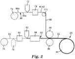
- a schematic view of one possible process for forming a web-wound roll such as the web-wound roll 20 of Fig. 2 , according to the present disclosure is depicted.
- the release liner 66 is unwound from a unwind stand 70.
- the release liner 66 has a first side 66a that may have been treated to possess release properties, and a second side 66b which preferably is left untreated.
- the stripes of coated material 40 and 42 conveniently in the form of a microsphere adhesive (MSA)
- MSA microsphere adhesive
- the release liner 66 is passed through a thermal oven 74 to dry the coated material 40, 42 to form edge-coated release liner 66'.
- One or more idle rolls such as roll 115 can be used to direct the release liner 66.
- the (co)polymeric film 62 is unwound from an unwind stand 76.
- the (co)polymeric film 62 such as that available under the trade designation MELINEX 454-200 film is obtained from a commercial source.
- the (co)polymeric film 62 receives a coating of hard coat material from a coater 78 to provide a wet coating of hard material which is dried by passing through a drier 80 to form the hard coat 60 of Fig. 2 .
- the coater 78 can be any convenient coating device such as one including a slot die to provide a uniform coating to the surface of the (co)polymeric film 62.
- the drier 80 can be any convenient drying or curing device such as, for example, a tunnel oven or a curing station using a UV source.
- the coating solution can be any commercially available hard coating solution which has appropriate viscosity to make it coatable.
- the optically clear adhesive 64 is coated by another coater 82 on the opposite side of the (co)polymeric film 62 and dried by a drier 84.
- the coating solution can be any convenient solution of a pressure sensitive adhesive.
- the twice coated substrate 62' and the once coated release liner 66' are brought together as at laminating station 86 and laminated together.
- the laminated material, together defining web 22, is conveyed to a winding stand 90, where the continuous web 22 is wound to form the web-wound roll 20.
- continuous refers to the length of a substrate web up to, for example, tens, hundreds, or even thousands of meters.
- (co)polymer or “(co)polymers” used herein refer to homopolymers and copolymers, as well as homopolymers or copolymers that may be formed in a miscible blend, e.g. , by coextrusion or by reaction, including, e.g. , transesterification.
- non-tacky generally means that the microspheres have a tack value of less than about 5 grams, preferably less than about 3 grams, and more preferably less than about 1 gram, as measured using a texture tack analyzer.
- elastomeric used herein can be described as applying to amorphous or non-crystalline materials that can be stretched to at least twice their original length (or diameter) and which will retract rapidly and forcibly to substantially their original dimensions upon release of the force.
- the term "repositionable” refers to the ability to be repeatedly adhered to and removed from a substrate without substantial loss of adhesion capability.
- release liner refers to a paper or plastic-based film sheet used to prevent a sticky surface from prematurely adhering, where it is coated on one or both sides with a release agent to provide a release effect against a sticky material such as an adhesive.
- a viscosity of "about” 1 Pa-sec refers to a viscosity from 0.95 to 1.05 Pa-sec, but also expressly includes a viscosity of exactly 1 Pa-sec.
- a perimeter that is “substantially square” is intended to describe a geometric shape having four lateral edges in which each lateral edge has a length which is from 95% to 105% of the length of any other lateral edge, but which also includes a geometric shape in which each lateral edge has exactly the same length.
- a substrate that is “substantially" transparent or optical clear refers to a substrate that transmits more radiation (e.g. visible light) than it fails to transmit (e.g. absorbs and reflects).
- a substrate that transmits more than 50% of the visible light incident upon its surface is substantially transparent, but a substrate that transmits 50% or less of the visible light incident upon its surface is not substantially transparent.
- MSA Microsphere Adhesive
- Microspheres containing a copolymer of 96 wt% of 2-Ethylhexylacrylate, 6 wt% of Acrylic acid, and 0.05 wt% of 1,4-Butanediol-diacrylate were prepared by suspension polymerization.
- the microspheres have an average particle diameter as measured by an optical microscopy, of about 30 microns and are suspended in a mixed solvent of 50 wt% of 2-propanol, 30 wt% of water, and 20 wt% of dioxolane to form the microsphere adhesive (MSA) which has a solid concentration of 1.5 wt%.
- MSA microsphere adhesive
- Example 1 a continuous web having 400 mm width was coated with the microsphere adhesive with a coating width of 25 mm along both web edges.
- the coating amount was about 55 cc/m 2 in wet, or about 60 microspheres were coated per mm 2 surface area.
- the continuous web was formed by the process of Fig. 3 with 2.5 microns thick hard coating, 15 microns thick PSA, 25 micron thick PET, and 38 microns thick release liner. Winding tension was set at 10N/400mm to wind the continuous web into a wound-web roll.
- Example 2 a continuous web is a 400 mm wide PET film with a release liner of silicone which has very low friction.
- the microsphere adhesive was coated with a coating width of 25 mm along both web edges.
- the coating amount was about 55 cc/m 2 in wet, or about 60 microspheres were coated per mm 2 surface area.
- Winding tension was set at 5N/400mm to wind the film into a wound-web roll.
- a continuous web is a 200 mm wide PET film having a thickness of 10 microns.
- the microsphere adhesive was coated with a coating width of 25 mm along both web edges.
- the coating amount was about 55 cc/m 2 in wet, or about 60 microspheres were coated per mm 2 surface area.
- Winding tension was set at 2N/200mm to wind the PET film into a wound-web roll.
- Comparative Example A a continuous web was the same as in Example 1, but without the microsphere adhesive coated along the web edges thereof.
- the winding impression defect was compared between Examples 1, 2 and 3, and Comparative Example A after unwinding a portion of each wound-web roll.
- Images for the examples were taken by using MAKYOH YIS-SP system from Yamashita Denso Corporation (Tokyo, Japan).
- the MAKYOH YIS-SP system utilizes the principle of magic mirror where when parallel beams of light are applied to a fine unevenness surface, the reflected light scatters at the convex part, which gives darker image, and condenses at the concave part, which gives brighter image. Winding impression defects were observed in the image of Comparative Example A, but not observed in the images for Examples 1, 2 and 3.
Description
- The present disclosure relates to web-wound rolls having a web edge treatment with microspheres, and processes to make the same.
- Winding impression defects are very common in a web-wound roll process for winding or rolling continuous films or webs. An inside pressure distribution of a web-wound roll can be made by, for example, surface roughness of the roll core, wrinkles, foreign matters, etc., which can generate impression defects and/or film deformation. Various approaches have been described in, for example,
PCT Publication No. WO 2011030684 (Maeda ), and Japanese Patent Application Publication Nos.JP 201346966 JP 2012247727 -
US 2010/291352 A1 discloses films with reinforced borders and edges having a low risk of the edges tearing during processing. -
US 2009/246478 A1 discloses an adhesive blend including a pressure sensitive adhesive and non-tacky microspheres that function as a detackifier. The blend can be coated onto a sheet to form a pad, such as an easel pad. -
WO 94/19420 - There is a desire to reduce winding impression defects in web-wound roll processes. While soft winding can be effective to reduce winding impression defects, soft winding may generate telescoping issues. The present disclosure provides soft winding processes for forming web-wound rolls that does not generate telescoping issues. The term "soft winding process" used herein refers to a web-wound roll process with a winding tension not greater than 1 N/cm, typically between 0.01 N/cm and 1 N/cm.
- Briefly, in one aspect, the present disclosure describes a web-wound roll that The invention is defined by the independent claims.
- According to the invention continuous films or webs can be wound by a soft winding process without generating any telescoping issues. In contrast, conventional approaches such as, for example, taper reducing tension, knurling of roll edge, insertion of spacer, or the combinations thereof, may not achieve the advantages of the present disclosure. For example, while a process using taper reducing wind tension control may be effective to reduce the winding impression, the effect of such process is limited by factors of web handling which depends on the web properties and equipment capability. While knurling on both web edges may provide the space between adjacent layers of wounded film and may reduce the inner pressure thereof, it is difficult to obtain stable knurling process with thin films or webs since it is easy to create critical damages on web edges. While insertion of spacer at both web edges may reduce the inner wound pressure, it would be difficult to control the position, thickness, and/or flexibility of spacer to achieve the effects.
- The disclosure may be more completely understood in consideration of the following detailed description of various embodiments of the disclosure in connection with the accompanying figures, in which:
-
Figure 1 is a perspective side view of a web-wound roll, according to one embodiment. -
Figure 2 is a cross sectional view of a portion of the web-wound roll ofFig. 1 . -
Figure 3 is a schematic view of a process for forming a web-wound roll, according to one embodiment. - In the drawings, like reference numerals indicate like elements. While the above-identified drawing, which may not be drawn to scale, sets forth various embodiments of the present disclosure, other embodiments are also contemplated, as noted in the Detailed Description. In all cases, this disclosure describes the presently disclosed disclosure by way of representation of exemplary embodiments and not by express limitations. It should be understood that numerous other modifications and embodiments can be devised by those skilled in the art, which fall within the scope of the claimed invention.
- The present disclosure provides web-wound rolls having a web edge treatment with microspheres (e.g., a microsphere adhesive), and processes to make the same. Some films or webs described herein can be wound by soft winding processes that are effective to reduce winding impression defect without generating telescoping issues.
-
Figure 1 illustrates a perspective view of a web-wound roll 20. The web-wound roll 20 includes acontinuous web 22 of indefinite length material. Thecontinuous web 22 is wound upon itself by a soft winding process inmultiple revolutions 24, conveniently around acentral core 26. In some embodiments, the soft winding process uses a winding tension not less than 0.01 N/cm, not less than 0.05 N/cm, or not less than 0.1 N/cm. In some embodiments, the soft winding process uses a winding tension not greater than 1 N/cm, not greater than 0.5 N/cm, or not greater than 0.2 N/cm. In some embodiments, the soft winding process uses a winding tension between 0.01 N/cm and 1 N/cm, between 0.05 N/cm and 1 N/cm, or between 0.1 N/cm and 0.5 N/cm. Thecontinuous web 22 has a firstmajor side 30 and a secondmajor side 32 opposite to the firstmajor side 30, and twoweb edges continuous web 22 has a width W1 defined between theweb edges - In some embodiments, the
continuous web 22 can include one or more layers of flexible (co)polymeric material. In some embodiments, thecontinuous web 22 can be a multi-layer optically clear laminate suited for attachment to, for example, window glass. One exemplary multi-layer optically clear laminate is described inU.S. Patent No. 7,238,401 (Dietz ). - Two stripes of coated
material major side 32. Thestripes web edges stripes respective web edges stripe respective web edge stripe respective web edge stripe respective web edge material respective web edges - In some embodiments, one or more stripes of coated material such as the
stripes major sides web edge stripes major side 30. In anther embodiment, thestripe 40 can be disposed on the firstmajor side 30 adjacent to theweb edge 34 and thestripe 42 can be disposed on the secondmajor side 32 adjacent to theweb edge 36. In yet another embodiment, one or more stripes of coated material can be disposed only adjacent to one of theweb edges - The coated material such as contained in the
stripes - In some embodiments, the adhesive blend can have from 1 to 50 parts by weight, preferably from 3 to 12 parts by weight of microspheres, and have from 50 to 99 parts by weight, preferably from 75 to 97 parts by weight of adhesive, based on the total weight of the adhesive and the microspheres. Other components can be used, including but not limited to, modifiers, such as rheology modifiers, colorants, fillers and other (co)polymeric additives. If such modifiers are used, the amounts used in the adhesive mixture are amounts effective for the known uses of such modifiers. One exemplary adhesive blend composition is described in
U.S. Patent Application Publication No. 20090246478 (Graham et al. ). - In some embodiments, at least a portion of the microspheres of the adhesive blend can be solid, elastomeric, deformable, and non-tacky microspheres. The non-tacky microspheres can be particularly suited as a detackifying agent. Thus, once blended with an adhesive composition such as a pressure sensitive adhesive (PSA) composition, the non-tacky microspheres of the present disclosure provide a useful tool to allow one to control the adhesion of the aggregate adhesive.
- In some embodiments, the microspheres can be solid and are non-crushable. The microspheres can also be substantially not swellable upon exposure to various solvents. The microspheres can have a highly crosslinked nature, and thus can be solvent insoluble. The microspheres can also be deformable, thereby allowing the substrate (e.g., the continuous web 20) coated with the adhesive blend to be wound up on itself without creating a hard band on a roll.
- In some embodiments, the microspheres can have an average diameter of, for example, from one micron to 200 microns. The microspheres can have an average diameter greater than the thickness of the adhesive coated on the substrate.
- In some embodiments, the microspheres of the adhesive blend can be prepared by a suspension polymerization process by polymerizing at least one alkyl(meth)acrylate monomer having from 1 to 14 carbon atoms, at least one multifunctional crosslinker, at least one initiator, and at least one polymeric stabilizer. Other optional components can be used in the reaction mixture, including but not limited to, surfactants.
- In some embodiments, the adhesive of the adhesive blend can include any pressure sensitive adhesive (PSA) composition that satisfies a rheological criterion for tack, for example, the Dahlquist criterion. The pressure sensitive adhesive can be solvent based, water based, or a hot melt, so long as the microspheres are compatible and stable therein. In one embodiment, the pressure sensitive adhesive is a repositionable adhesive. A suitable pressure sensitive adhesive for use in the adhesive blend of the present disclosure is described in
PCT Publication WO 1994/019420 . The publication describes a repositionable pressure sensitive adhesive composition comprising a blend of one or more polymeric, inherently tacky, elastomeric microspheres and an adhesive binder comprising at least one acrylamide-based moiety. It is to be understood that the adhesive blend can include any suitable adhesives other than the pressure sensitive adhesive. - Referring now to
Fig. 2 , a cross section view of several of thewound revolutions 24, taken along section lines 2-2 inFig. 1 , is depicted. In this view it can be appreciated that each ofrevolutions continuous web 22 is held substantially separate from the next by thestripes Spaces 50 can be created betweenadjacent revolutions stripes spaces 50 to keep the adjacent revolutions separate. - As shown in
Fig. 2 , thestripes second side 32 adjacent to the respective web edges 34 and 36. Thestripes first side 30 of the adjacent revolution and the friction therebetween prevents relative axial movement between adjacent revolutions, and thus prevent possible telescoping issues. - The
continuous web 22 ofFigs. 1 and 2 can be an optical film where any scratches or defects such as winding impression defects and/or film deformation may be plainly visible therein with the naked eye when viewed under, for example, fluorescent lights at a distance of about 0.5 m. In the embodiment ofFig. 2 , thecontinuous web 22 is a laminate that includes ahard coat 60 adhered to a (co)polymeric film 62 which is laminated to arelease liner 66 by an optically clear adhesive (OCA) 64. - In some embodiments, the
hard coat 60 may be obtained by applying any commercially available hard coating composition to the surface of the (co)polymeric film 62, as the case may be, provided that the resultant hard coat layer dries to form a scratch-resistant surface. The hard coating composition can be, for example, a ceramer coating composition containing an organic resin and silica particles as described inU.S. Pat. No. 5,677,050 (Bilkadi et al. ). In some embodiments, the hard coating composition may include about 20% to about 80 wt% of ethylenically unsaturated monomers, about 10 wt% to about 50 wt% of acrylate functionalized colloidal silica, and about 5 wt% to about 40 wt% of N,N-disubstituted acrylamide monomer or N-substituted-N-vinyl-amide monomer. The coating can then be cured to provide an abrasion-resistant, light transmissive ceramer coating on the top film lamina of the laminate. The hard coating is preferably applied to the film before it is used to form the laminate. - In some embodiments, the (co)
polymeric film 62 may include any suitable polymeric material. The polymeric material can be nonadhesive and may be formed into a sheet which is of substantially uniform thickness along its entire area and is optically clear with substantially no surface imperfections which might interfere with optically clarity. The term "nonadhesive" means that the polymeric material used to form the film is not an adhesive type material such as conventionally used to make glass or layered film laminates. Such adhesive polymeric materials would include thermoplastic adhesive materials such as polyvinyl butyral, ethylene terpolymers, epoxies, polyurethanes, silicones and acrylic polymers. In one embodiment, thepolymeric film 62 is a polyethylene terephthalate (PET) film. The (co)polymeric film 62 may vary in thickness not less than 0.5 mil (0.013 mm), not less than 1 mil (0.025 mm), or not less than 1.5 mils (0.038 mm). The (co)polymeric film 62 may vary in thickness not greater than 20 mils (0.508 mm), not greater than 10 mils (0.254 mm), or not greater than 5 mils (0.127 mm). The (co)polymeric film 62 may vary in thickness from about 0.5 mil to about 10 mils (0.013 to 0.25 mm), but preferably do not exceed about 5 mils (0.13 mm) in thickness. The (co)polymeric film 62 may be made of polymeric material such as polyethylene-terephthalate (PET) which when formed into a sheet, biaxially oriented and heat set provides a high breaking strength film with excellent optical properties. In some embodiments, the polymeric films can be primed or corona treated to improve adhesion between coatings and adhesive layers. - In some embodiments, the optically clear adhesive (OCA) 64 between the (co)
polymeric film 62 and therelease liner 66 may include any relatively soft pressure sensitive adhesive material that can be optically clear, for example, having a transmittance not less than 50% in the visible wavelength range. The pressure sensitive adhesive material may, itself, not be optically clear in a free standing condition but once incorporated into the laminate can have an optically clear condition and sufficient adhesion to maintain the layers of the laminate in an unaltered form over any of a wide variety of climatic conditions. The pressure sensitive adhesive compositions can be based on acrylate or acrylic copolymers and terpolymers. The thickness of the optically clear adhesive (OCA) 64 may vary, for example, from about 0.1 mil to about 1 mil (0.003 to 0.025 mm). - In some embodiments, the
release liner 66 may include any conventional sheet material. Therelease liner 66 provides protection for the exposed surface of the optically clear adhesive (OCA) 64. Therelease liner 66 may have temporary weak adhesion to the surface of optically clear adhesive (OCA) 64 to which it is applied, and thus can strip cleanly from the surface to leave behind an undamaged layer of adhesive for attachment to the surface of, for example, a glass sheet. - Referring again to
Fig. 2 , thestripes release liner 66 of one revolution and in contact with thehard coat 60 of the adjacent revolution. The stripes described herein use an adhesive blend that contains solid, elastomeric, non-tacky microspheres with a pressure sensitive adhesive. The adhesive blend is capable of adhering to the surface of therelease liner 66 to form thestripes release liner 66 can be removed and thestripes release liner 66. In some embodiments, the web edges 34 and 36 along with thestripes - Referring now to
Fig. 3 , a schematic view of one possible process for forming a web-wound roll such as the web-wound roll 20 ofFig. 2 , according to the present disclosure is depicted. Therelease liner 66 is unwound from a unwindstand 70. In the depicted embodiment, therelease liner 66 has afirst side 66a that may have been treated to possess release properties, and asecond side 66b which preferably is left untreated. The stripes ofcoated material second side 66b, conveniently by acoater 72 such as, for example, a gravure coater. When thecoated material release liner 66, therelease liner 66 is passed through a thermal oven 74 to dry thecoated material roll 115 can be used to direct therelease liner 66. - In the embodiment of
Fig. 3 , the (co)polymeric film 62 is unwound from an unwindstand 76. The (co)polymeric film 62 such as that available under the trade designation MELINEX 454-200 film is obtained from a commercial source. The (co)polymeric film 62 receives a coating of hard coat material from acoater 78 to provide a wet coating of hard material which is dried by passing through a drier 80 to form thehard coat 60 ofFig. 2 . Thecoater 78 can be any convenient coating device such as one including a slot die to provide a uniform coating to the surface of the (co)polymeric film 62. The drier 80 can be any convenient drying or curing device such as, for example, a tunnel oven or a curing station using a UV source. The coating solution can be any commercially available hard coating solution which has appropriate viscosity to make it coatable. Then, the opticallyclear adhesive 64 is coated by anothercoater 82 on the opposite side of the (co)polymeric film 62 and dried by a drier 84. The coating solution can be any convenient solution of a pressure sensitive adhesive. The twice coated substrate 62' and the once coated release liner 66' are brought together as at laminatingstation 86 and laminated together. The laminated material, together definingweb 22, is conveyed to a windingstand 90, where thecontinuous web 22 is wound to form the web-wound roll 20. - For the following Glossary of defined terms, these definitions shall be applied for the entire application, unless a different definition is provided in the claims or elsewhere in the specification.
- Certain terms are used throughout the description and the claims that, while for the most part are well known, may require some explanation. It should be understood that:
The term "continuous" used herein refers to the length of a substrate web up to, for example, tens, hundreds, or even thousands of meters. - The terms "(co)polymer" or "(co)polymers" used herein refer to homopolymers and copolymers, as well as homopolymers or copolymers that may be formed in a miscible blend, e.g., by coextrusion or by reaction, including, e.g., transesterification.
- The term "non-tacky" generally means that the microspheres have a tack value of less than about 5 grams, preferably less than about 3 grams, and more preferably less than about 1 gram, as measured using a texture tack analyzer.
- The term "elastomeric" used herein can be described as applying to amorphous or non-crystalline materials that can be stretched to at least twice their original length (or diameter) and which will retract rapidly and forcibly to substantially their original dimensions upon release of the force.
- As used herein, the term "repositionable" refers to the ability to be repeatedly adhered to and removed from a substrate without substantial loss of adhesion capability.
- The term "release liner" used herein refers to a paper or plastic-based film sheet used to prevent a sticky surface from prematurely adhering, where it is coated on one or both sides with a release agent to provide a release effect against a sticky material such as an adhesive.
- The terms "about" or "approximately" with reference to a numerical value or a shape means +/- five percent of the numerical value or property or characteristic, but expressly includes the exact numerical value. For example, a viscosity of "about" 1 Pa-sec refers to a viscosity from 0.95 to 1.05 Pa-sec, but also expressly includes a viscosity of exactly 1 Pa-sec. Similarly, a perimeter that is "substantially square" is intended to describe a geometric shape having four lateral edges in which each lateral edge has a length which is from 95% to 105% of the length of any other lateral edge, but which also includes a geometric shape in which each lateral edge has exactly the same length.
- The term "substantially" with reference to a property or characteristic means that the property or characteristic is exhibited to a greater extent than the opposite of that property or characteristic is exhibited. For example, a substrate that is "substantially" transparent or optical clear refers to a substrate that transmits more radiation (e.g. visible light) than it fails to transmit (e.g. absorbs and reflects). Thus, a substrate that transmits more than 50% of the visible light incident upon its surface is substantially transparent, but a substrate that transmits 50% or less of the visible light incident upon its surface is not substantially transparent.
- As used in this specification and the appended embodiments, the singular forms "a", "an", and "the" include plural referents unless the content clearly dictates otherwise. Thus, for example, reference to fine fibers containing "a compound" includes a mixture of two or more compounds. As used in this specification and the appended embodiments, the term "or" is generally employed in its sense including "and/or" unless the content clearly dictates otherwise.
- Listing of non claimed embodiments:
- Exemplary embodiments are listed below. It is to be understood that any one of embodiments A to M and N to X can be combined.
- Embodiment A is an article comprising:
- a web comprising a substrate having a first major side and a second major side opposite to the first major side, and at least two web edges;
- one or more stripes of coated material having a thickness and disposed on one or both of the first and second major sides adjacent to one or both of the web edges,
- wherein the substrate is rolled upon itself in multiple revolutions about a central core, and
- wherein each revolution is held substantially separate from the next by the one or more stripes of coated material which comprises an adhesive blend including an adhesive and microspheres to provide a friction and prevent a relative axial movement between adjacent revolutions.
- Embodiment B is the article of embodiment A, wherein the thickness of the one or more stripes of coated material is from 0.5 microns to 100 microns.
- Embodiment F is the article of embodiment A, wherein the adhesive blend comprises from about 1 to 50 parts by weight of microspheres and from about 50 to 99 parts by weight of an adhesive.
- Embodiment G is the article of embodiment C, wherein the microspheres include solid, elastomeric, deformable, and non-tacky microspheres.
- Embodiment H is the article of embodiment F or G, wherein the microspheres have an average diameter greater than a coating thickness of the adhesive on the substrate.
- Embodiment I is the article of any one of embodiments F to H, wherein the adhesive comprises a pressure sensitive adhesive (PSA).
- Embodiment J is the article of embodiment I, wherein the pressure sensitive adhesive is a repositionable adhesive.
- Embodiment K is the article of any one of the preceding embodiments, wherein the one or more stripes of coated material each have a width W1, the continuous web has a width W2, and the ratio of W1/W2 is between 0.01 to 0.2.
- Embodiment L is the article of any one of the preceding embodiments, wherein the substrate includes a flexible polymeric film.
- Embodiment M is the article of any one of the preceding embodiments, wherein the continuous web is a multi-layer optically clear laminate that includes a release liner, and the one or more stripes of coated material are disposed on a surface of the release liner along one or more of the web edges.
- Embodiment N is a method comprising:
- providing a continuous web comprising a substrate web having a first major side and a second major side opposite to the first major side, and at least two web edges;
- disposing one or more stripes of coated material having a thickness on one or both of the first and second major sides adjacent to one or both of the web edges; and winding the substrate web upon itself in multiple revolutions about a central core,
- wherein each revolution is held substantially separate from the next by the one or more stripes of coated material which comprises an adhesive blend including an adhesive and microspheres to provide a friction and prevent a relative axial movement between adjacent revolutions.
- Embodiment O is the method of embodiment N, wherein the substrate web is wound in a roll-to-roll process with a winding tension not greater than 1 N/cm.
- Embodiment P is the method of embodiment O, wherein the winding tension is between 0.1 N/cm and 0.5 N/cm.
- Embodiment T is the method of embodiment N, wherein the adhesive blend comprises from about 1 to 50 parts by weight of microspheres and from about 50 to 99 parts by weight of an adhesive.
- Embodiment U is the method of any one of embodiments N or T, wherein the microspheres include solid, elastomeric, deformable, and non-tacky microspheres.
- Embodiment V is the method of embodiment U, wherein the microspheres have an average diameter greater than a coating thickness of the adhesive on the substrate.
- Embodiment W is the method of embodiment N, wherein the adhesive comprises a pressure sensitive adhesive (PSA).
- Embodiment X is the method of embodiment W, wherein the pressure sensitive adhesive is a repositionable adhesive.
- The operation of the present disclosure will be further described with regard to the following detailed examples. These examples are offered to further illustrate the various specific and preferred embodiments and techniques. It should be understood, however, that many variations and modifications may be made while remaining within the scope of the present disclosure.
- Microspheres containing a copolymer of 96 wt% of 2-Ethylhexylacrylate, 6 wt% of Acrylic acid, and 0.05 wt% of 1,4-Butanediol-diacrylate were prepared by suspension polymerization. The microspheres have an average particle diameter as measured by an optical microscopy, of about 30 microns and are suspended in a mixed solvent of 50 wt% of 2-propanol, 30 wt% of water, and 20 wt% of dioxolane to form the microsphere adhesive (MSA) which has a solid concentration of 1.5 wt%.
- In Example 1, a continuous web having 400 mm width was coated with the microsphere adhesive with a coating width of 25 mm along both web edges. The coating amount was about 55 cc/m2 in wet, or about 60 microspheres were coated per mm2 surface area. The continuous web was formed by the process of
Fig. 3 with 2.5 microns thick hard coating, 15 microns thick PSA, 25 micron thick PET, and 38 microns thick release liner. Winding tension was set at 10N/400mm to wind the continuous web into a wound-web roll. - In Example 2, a continuous web is a 400 mm wide PET film with a release liner of silicone which has very low friction. The microsphere adhesive was coated with a coating width of 25 mm along both web edges. The coating amount was about 55 cc/m2 in wet, or about 60 microspheres were coated per mm2 surface area. Winding tension was set at 5N/400mm to wind the film into a wound-web roll.
- In Example 3, a continuous web is a 200 mm wide PET film having a thickness of 10 microns. The microsphere adhesive was coated with a coating width of 25 mm along both web edges. The coating amount was about 55 cc/m2 in wet, or about 60 microspheres were coated per mm2 surface area. Winding tension was set at 2N/200mm to wind the PET film into a wound-web roll.
- In Comparative Example A, a continuous web was the same as in Example 1, but without the microsphere adhesive coated along the web edges thereof.
- The winding impression defect was compared between Examples 1, 2 and 3, and Comparative Example A after unwinding a portion of each wound-web roll. Images for the examples were taken by using MAKYOH YIS-SP system from Yamashita Denso Corporation (Tokyo, Japan). The MAKYOH YIS-SP system utilizes the principle of magic mirror where when parallel beams of light are applied to a fine unevenness surface, the reflected light scatters at the convex part, which gives darker image, and condenses at the concave part, which gives brighter image. Winding impression defects were observed in the image of Comparative Example A, but not observed in the images for Examples 1, 2 and 3.
Claims (12)
- An article comprising:a continuous web comprising a substrate having a first major side and a second major side opposite to the first major side, and at least two web edges;one or more stripes of coated material having a thickness and disposed on one or both of the first and second major sides adjacent to one or both of the web edges,wherein the substrate is rolled upon itself in multiple revolutions about a central core, andwherein each revolution is held substantially separate from the next by the one or more stripes of coated material which comprises an adhesive blend including an adhesive and microspheres to provide a friction and prevent a relative axial movement between adjacent revolutions.
- The article of claim 1, wherein the thickness of the one or more stripes of coated material is from 0.5 microns to 100 microns.
- The article of claim 1, wherein the adhesive blend comprises from about 1 to 50 parts by weight of microspheres and from about 50 to 99 parts by weight of an adhesive.
- The article of claim 1, wherein the microspheres include solid, elastomeric, deformable, and non-tacky microspheres.
- The article of claim 1, wherein the microspheres have an average diameter greater than a coating thickness of the adhesive on the substrate.
- The article of claim 1, wherein the adhesive comprises a pressure sensitive adhesive (PSA).
- The article of claim 6, wherein the pressure sensitive adhesive is a repositionable adhesive.
- The article of claim 1, wherein the one or more stripes of coated material each have a width W1, the continuous web has a width W2, and the ratio of W1/W2 is between 0.01 to 0.2.
- The article of claim 1, wherein the continuous web is a multi-layer optically clear laminate that includes a release liner, and the one or more stripes of coated material are disposed on a surface of the release liner along one or more of the web edges.
- A method comprising:providing a continuous web comprising a substrate web having a first major side and a second major side opposite to the first major side, and at least two web edges;disposing one or more stripes of coated material having a thickness on one or both of the first and second major sides adjacent to one or both of the web edges; andwinding the substrate upon itself in multiple revolutions about a central core,wherein each revolution is held substantially separate from the next by the one or more stripes of coated material which comprises an adhesive blend including an adhesive and microspheres to provide a friction and prevent a relative axial movement between adjacent revolutions.
- The method of claim 10, wherein the substrate web is wound in a roll-to-roll process with a winding tension not greater than 1 N/cm.
- The method of claim 11, wherein the winding tension is between 0.1 N/cm and 0.5 N/cm.
Applications Claiming Priority (2)
| Application Number | Priority Date | Filing Date | Title |
|---|---|---|---|
| US201462097729P | 2014-12-30 | 2014-12-30 | |
| PCT/US2015/066089 WO2016109205A1 (en) | 2014-12-30 | 2015-12-16 | Web-wound rolls with microsphere treated edge and methods of making same |
Publications (3)
| Publication Number | Publication Date |
|---|---|
| EP3240750A1 EP3240750A1 (en) | 2017-11-08 |
| EP3240750A4 EP3240750A4 (en) | 2018-11-07 |
| EP3240750B1 true EP3240750B1 (en) | 2022-08-10 |
Family
ID=56284906
Family Applications (1)
| Application Number | Title | Priority Date | Filing Date |
|---|---|---|---|
| EP15875963.9A Active EP3240750B1 (en) | 2014-12-30 | 2015-12-16 | Web-wound rolls with microsphere treated edge and methods of making same |
Country Status (7)
| Country | Link |
|---|---|
| US (1) | US20170369264A1 (en) |
| EP (1) | EP3240750B1 (en) |
| JP (1) | JP6872485B2 (en) |
| KR (1) | KR102518124B1 (en) |
| CN (1) | CN107108140B (en) |
| SG (1) | SG11201705383TA (en) |
| WO (1) | WO2016109205A1 (en) |
Families Citing this family (4)
| Publication number | Priority date | Publication date | Assignee | Title |
|---|---|---|---|---|
| WO2020012651A1 (en) * | 2018-07-13 | 2020-01-16 | 日立化成株式会社 | Method for manufacturing photosensitive film roll for sensing device, and photosensitive film roll for sensing device |
| CN112513390B (en) * | 2018-12-11 | 2023-06-27 | Gcp应用技术有限公司 | Pre-laid film with anti-dive layer |
| CN114786949B (en) * | 2019-12-19 | 2024-02-06 | 豪夫迈·罗氏有限公司 | Method and system for producing a plurality of analytical test strips |
| CN114104793A (en) * | 2021-11-10 | 2022-03-01 | 深圳市三利谱光电科技股份有限公司 | Polaroid storage roll, auxiliary tool for polaroid storage roll and manufacturing method |
Family Cites Families (20)
| Publication number | Priority date | Publication date | Assignee | Title |
|---|---|---|---|---|
| NL7102978A (en) * | 1970-03-17 | 1971-09-21 | ||
| JPS5948511U (en) * | 1982-09-25 | 1984-03-31 | 日東電工株式会社 | Structure of rolled adhesive polarizing plate |
| CA2156164A1 (en) | 1993-02-16 | 1994-09-01 | Lori A. Bilski | System comprising release agent and high peel adhesion repositionable adhesive |
| US5677050A (en) | 1995-05-19 | 1997-10-14 | Minnesota Mining And Manufacturing Company | Retroreflective sheeting having an abrasion resistant ceramer coating |
| JP2000108228A (en) * | 1998-10-06 | 2000-04-18 | Dainippon Printing Co Ltd | Roll film and its manufacture |
| US7238401B1 (en) * | 2000-06-09 | 2007-07-03 | 3M Innovative Properties Company | Glazing element and laminate for use in the same |
| FR2812652B1 (en) * | 2000-08-04 | 2005-05-20 | Plasto Sa | STACKABLE ADHESIVE STRIPS WITHOUT PROTECTOR |
| US20070089832A1 (en) * | 2005-09-15 | 2007-04-26 | Kitchin Jonathan P | Repositionable matte photo media |
| JP2007186594A (en) * | 2006-01-13 | 2007-07-26 | Toray Advanced Film Co Ltd | Coated film |
| JP5153283B2 (en) * | 2007-10-01 | 2013-02-27 | 大王製紙株式会社 | Side tape for optical film |
| SI2047985T1 (en) * | 2007-10-10 | 2013-11-29 | Duo-Plast Ag | Films with reinforced edges |
| US8110280B2 (en) * | 2008-03-27 | 2012-02-07 | 3M Innovative Properties Company | Adhesive composition having non-tacky microspheres and sheets made therefrom |
| DE102008059384A1 (en) * | 2008-06-03 | 2009-12-17 | Tesa Se | Adhesive tape and its use |
| CN102483481B (en) | 2009-09-14 | 2015-04-08 | 柯尼卡美能达精密光学株式会社 | Method of manufacturing optical film |
| EP2516574A1 (en) * | 2009-12-22 | 2012-10-31 | 3M Innovative Properties Company | Adhesive sheet with differentially thick release coating |
| JP5795596B2 (en) * | 2009-12-22 | 2015-10-14 | スリーエム イノベイティブ プロパティズ カンパニー | Method and apparatus for producing a non-uniform coating on a substrate |
| JP2012122027A (en) * | 2010-12-10 | 2012-06-28 | Nitto Denko Corp | Pressure-sensitive adhesive tape or sheet |
| JP4985865B1 (en) | 2011-05-31 | 2012-07-25 | パナソニック株式会社 | Image display device |
| JP5751094B2 (en) | 2011-08-29 | 2015-07-22 | コニカミノルタ株式会社 | Manufacturing method of optical film |
| EP2938686A1 (en) * | 2012-12-28 | 2015-11-04 | 3M Innovative Properties Company | Articles with adhesive separation layer |
-
2015
- 2015-12-16 JP JP2017535350A patent/JP6872485B2/en active Active
- 2015-12-16 SG SG11201705383TA patent/SG11201705383TA/en unknown
- 2015-12-16 WO PCT/US2015/066089 patent/WO2016109205A1/en active Application Filing
- 2015-12-16 EP EP15875963.9A patent/EP3240750B1/en active Active
- 2015-12-16 KR KR1020177021203A patent/KR102518124B1/en active IP Right Grant
- 2015-12-16 CN CN201580071937.0A patent/CN107108140B/en active Active
- 2015-12-16 US US15/539,335 patent/US20170369264A1/en active Pending
Also Published As
| Publication number | Publication date |
|---|---|
| SG11201705383TA (en) | 2017-07-28 |
| WO2016109205A1 (en) | 2016-07-07 |
| EP3240750A1 (en) | 2017-11-08 |
| CN107108140B (en) | 2020-02-18 |
| JP6872485B2 (en) | 2021-05-19 |
| KR20170100647A (en) | 2017-09-04 |
| EP3240750A4 (en) | 2018-11-07 |
| CN107108140A (en) | 2017-08-29 |
| US20170369264A1 (en) | 2017-12-28 |
| JP2018506450A (en) | 2018-03-08 |
| KR102518124B1 (en) | 2023-04-05 |
Similar Documents
| Publication | Publication Date | Title |
|---|---|---|
| EP3240750B1 (en) | Web-wound rolls with microsphere treated edge and methods of making same | |
| JP6258681B2 (en) | Surface protective film and optical member | |
| KR102199874B1 (en) | Optical film, peeling method, and manufacturing method of optical display panel | |
| JP5855465B2 (en) | Surface protective film, optical component on which it is adhered, and industrial product | |
| KR101987643B1 (en) | Release film having excellent peelability | |
| KR102166983B1 (en) | Method for producing a single protective polarizing film with a transparent resin layer, a method for producing a polarizing film with an adhesive layer, and a method for producing an optical laminate | |
| JP6323033B2 (en) | Adhesive film and method of using the same | |
| EP2088179A1 (en) | Releasable adhesive sheet | |
| WO2017122732A1 (en) | One-side-protected polarizing film with adhesive layer, image display device, and continuous production method for same | |
| JP2023061955A (en) | Optical film and optical display panel | |
| WO2012085204A1 (en) | Pressure sensitive adhesive tape | |
| JP6767143B2 (en) | Release film peeling method and optical display panel manufacturing method | |
| KR101920635B1 (en) | Surface-protective film and optical component attached with the same | |
| JP2005154689A (en) | Pressure sensitive adhesive sheet with separator, optical member-assembling body, and method for assembling the same | |
| KR20180132582A (en) | Surface-protective film and optical component attached with the same | |
| KR102636897B1 (en) | Method for manufacturing a packing material of an optical member | |
| JP6761084B2 (en) | Manufacturing method of antistatic surface protective film | |
| JP7258497B2 (en) | transparent adhesive film | |
| CN109283608A (en) | Optical sheet | |
| JP2002173650A (en) | Pressure-sensitive adhesive film for protecting optical sheet | |
| JP2010077284A (en) | Pressure-sensitive adhesive sheet roll | |
| JP2016064666A (en) | Adherend adhesive film, and optical component and industrial product to which adherend adhesive film is stuck | |
| WO2017164065A1 (en) | Surface-protecting film-equipped polarizing film, and method for producing polarizing film | |
| JP2002309188A (en) | Pressure-sensitive sheet |
Legal Events
| Date | Code | Title | Description |
|---|---|---|---|
| STAA | Information on the status of an ep patent application or granted ep patent |
Free format text: STATUS: THE INTERNATIONAL PUBLICATION HAS BEEN MADE |
|
| PUAI | Public reference made under article 153(3) epc to a published international application that has entered the european phase |
Free format text: ORIGINAL CODE: 0009012 |
|
| STAA | Information on the status of an ep patent application or granted ep patent |
Free format text: STATUS: REQUEST FOR EXAMINATION WAS MADE |
|
| 17P | Request for examination filed |
Effective date: 20170706 |
|
| AK | Designated contracting states |
Kind code of ref document: A1 Designated state(s): AL AT BE BG CH CY CZ DE DK EE ES FI FR GB GR HR HU IE IS IT LI LT LU LV MC MK MT NL NO PL PT RO RS SE SI SK SM TR |
|
| AX | Request for extension of the european patent |
Extension state: BA ME |
|
| DAV | Request for validation of the european patent (deleted) | ||
| DAX | Request for extension of the european patent (deleted) | ||
| RIC1 | Information provided on ipc code assigned before grant |
Ipc: B65H 37/02 20060101ALI20180626BHEP Ipc: B32B 37/20 20060101AFI20180626BHEP Ipc: B65H 37/00 20060101ALI20180626BHEP Ipc: B65H 37/04 20060101ALI20180626BHEP |
|
| REG | Reference to a national code |
Ref country code: DE Ref legal event code: R079 Ref document number: 602015080309 Country of ref document: DE Free format text: PREVIOUS MAIN CLASS: B65H0037000000 Ipc: B32B0037200000 |
|
| A4 | Supplementary search report drawn up and despatched |
Effective date: 20181010 |
|
| RIC1 | Information provided on ipc code assigned before grant |
Ipc: B65H 37/04 20060101ALI20181004BHEP Ipc: B65H 37/00 20060101ALI20181004BHEP Ipc: B65H 37/02 20060101ALI20181004BHEP Ipc: B32B 37/20 20060101AFI20181004BHEP |
|
| STAA | Information on the status of an ep patent application or granted ep patent |
Free format text: STATUS: EXAMINATION IS IN PROGRESS |
|
| STAA | Information on the status of an ep patent application or granted ep patent |
Free format text: STATUS: EXAMINATION IS IN PROGRESS |
|
| 17Q | First examination report despatched |
Effective date: 20201016 |
|
| STAA | Information on the status of an ep patent application or granted ep patent |
Free format text: STATUS: EXAMINATION IS IN PROGRESS |
|
| GRAP | Despatch of communication of intention to grant a patent |
Free format text: ORIGINAL CODE: EPIDOSNIGR1 |
|
| INTG | Intention to grant announced |
Effective date: 20220310 |
|
| STAA | Information on the status of an ep patent application or granted ep patent |
Free format text: STATUS: GRANT OF PATENT IS INTENDED |
|
| GRAS | Grant fee paid |
Free format text: ORIGINAL CODE: EPIDOSNIGR3 |
|
| GRAA | (expected) grant |
Free format text: ORIGINAL CODE: 0009210 |
|
| STAA | Information on the status of an ep patent application or granted ep patent |
Free format text: STATUS: THE PATENT HAS BEEN GRANTED |
|
| AK | Designated contracting states |
Kind code of ref document: B1 Designated state(s): AL AT BE BG CH CY CZ DE DK EE ES FI FR GB GR HR HU IE IS IT LI LT LU LV MC MK MT NL NO PL PT RO RS SE SI SK SM TR |
|
| REG | Reference to a national code |
Ref country code: AT Ref legal event code: REF Ref document number: 1510227 Country of ref document: AT Kind code of ref document: T Effective date: 20220815 Ref country code: CH Ref legal event code: EP |
|
| REG | Reference to a national code |
Ref country code: IE Ref legal event code: FG4D |
|
| REG | Reference to a national code |
Ref country code: DE Ref legal event code: R096 Ref document number: 602015080309 Country of ref document: DE |
|
| GRAP | Despatch of communication of intention to grant a patent |
Free format text: ORIGINAL CODE: EPIDOSNIGR1 |
|
| REG | Reference to a national code |
Ref country code: NL Ref legal event code: MP Effective date: 20220810 |
|
| REG | Reference to a national code |
Ref country code: LT Ref legal event code: MG9D |
|
| PG25 | Lapsed in a contracting state [announced via postgrant information from national office to epo] |
Ref country code: SE Free format text: LAPSE BECAUSE OF FAILURE TO SUBMIT A TRANSLATION OF THE DESCRIPTION OR TO PAY THE FEE WITHIN THE PRESCRIBED TIME-LIMIT Effective date: 20220810 Ref country code: RS Free format text: LAPSE BECAUSE OF FAILURE TO SUBMIT A TRANSLATION OF THE DESCRIPTION OR TO PAY THE FEE WITHIN THE PRESCRIBED TIME-LIMIT Effective date: 20220810 Ref country code: PT Free format text: LAPSE BECAUSE OF FAILURE TO SUBMIT A TRANSLATION OF THE DESCRIPTION OR TO PAY THE FEE WITHIN THE PRESCRIBED TIME-LIMIT Effective date: 20221212 Ref country code: NO Free format text: LAPSE BECAUSE OF FAILURE TO SUBMIT A TRANSLATION OF THE DESCRIPTION OR TO PAY THE FEE WITHIN THE PRESCRIBED TIME-LIMIT Effective date: 20221110 Ref country code: NL Free format text: LAPSE BECAUSE OF FAILURE TO SUBMIT A TRANSLATION OF THE DESCRIPTION OR TO PAY THE FEE WITHIN THE PRESCRIBED TIME-LIMIT Effective date: 20220810 Ref country code: LV Free format text: LAPSE BECAUSE OF FAILURE TO SUBMIT A TRANSLATION OF THE DESCRIPTION OR TO PAY THE FEE WITHIN THE PRESCRIBED TIME-LIMIT Effective date: 20220810 Ref country code: LT Free format text: LAPSE BECAUSE OF FAILURE TO SUBMIT A TRANSLATION OF THE DESCRIPTION OR TO PAY THE FEE WITHIN THE PRESCRIBED TIME-LIMIT Effective date: 20220810 Ref country code: FI Free format text: LAPSE BECAUSE OF FAILURE TO SUBMIT A TRANSLATION OF THE DESCRIPTION OR TO PAY THE FEE WITHIN THE PRESCRIBED TIME-LIMIT Effective date: 20220810 Ref country code: ES Free format text: LAPSE BECAUSE OF FAILURE TO SUBMIT A TRANSLATION OF THE DESCRIPTION OR TO PAY THE FEE WITHIN THE PRESCRIBED TIME-LIMIT Effective date: 20220810 |
|
| REG | Reference to a national code |
Ref country code: AT Ref legal event code: MK05 Ref document number: 1510227 Country of ref document: AT Kind code of ref document: T Effective date: 20220810 |
|
| PG25 | Lapsed in a contracting state [announced via postgrant information from national office to epo] |
Ref country code: PL Free format text: LAPSE BECAUSE OF FAILURE TO SUBMIT A TRANSLATION OF THE DESCRIPTION OR TO PAY THE FEE WITHIN THE PRESCRIBED TIME-LIMIT Effective date: 20220810 Ref country code: IS Free format text: LAPSE BECAUSE OF FAILURE TO SUBMIT A TRANSLATION OF THE DESCRIPTION OR TO PAY THE FEE WITHIN THE PRESCRIBED TIME-LIMIT Effective date: 20221210 Ref country code: HR Free format text: LAPSE BECAUSE OF FAILURE TO SUBMIT A TRANSLATION OF THE DESCRIPTION OR TO PAY THE FEE WITHIN THE PRESCRIBED TIME-LIMIT Effective date: 20220810 Ref country code: GR Free format text: LAPSE BECAUSE OF FAILURE TO SUBMIT A TRANSLATION OF THE DESCRIPTION OR TO PAY THE FEE WITHIN THE PRESCRIBED TIME-LIMIT Effective date: 20221111 |
|
| PG25 | Lapsed in a contracting state [announced via postgrant information from national office to epo] |
Ref country code: SM Free format text: LAPSE BECAUSE OF FAILURE TO SUBMIT A TRANSLATION OF THE DESCRIPTION OR TO PAY THE FEE WITHIN THE PRESCRIBED TIME-LIMIT Effective date: 20220810 Ref country code: RO Free format text: LAPSE BECAUSE OF FAILURE TO SUBMIT A TRANSLATION OF THE DESCRIPTION OR TO PAY THE FEE WITHIN THE PRESCRIBED TIME-LIMIT Effective date: 20220810 Ref country code: DK Free format text: LAPSE BECAUSE OF FAILURE TO SUBMIT A TRANSLATION OF THE DESCRIPTION OR TO PAY THE FEE WITHIN THE PRESCRIBED TIME-LIMIT Effective date: 20220810 Ref country code: CZ Free format text: LAPSE BECAUSE OF FAILURE TO SUBMIT A TRANSLATION OF THE DESCRIPTION OR TO PAY THE FEE WITHIN THE PRESCRIBED TIME-LIMIT Effective date: 20220810 Ref country code: AT Free format text: LAPSE BECAUSE OF FAILURE TO SUBMIT A TRANSLATION OF THE DESCRIPTION OR TO PAY THE FEE WITHIN THE PRESCRIBED TIME-LIMIT Effective date: 20220810 |
|
| REG | Reference to a national code |
Ref country code: DE Ref legal event code: R097 Ref document number: 602015080309 Country of ref document: DE |
|
| PG25 | Lapsed in a contracting state [announced via postgrant information from national office to epo] |
Ref country code: SK Free format text: LAPSE BECAUSE OF FAILURE TO SUBMIT A TRANSLATION OF THE DESCRIPTION OR TO PAY THE FEE WITHIN THE PRESCRIBED TIME-LIMIT Effective date: 20220810 Ref country code: EE Free format text: LAPSE BECAUSE OF FAILURE TO SUBMIT A TRANSLATION OF THE DESCRIPTION OR TO PAY THE FEE WITHIN THE PRESCRIBED TIME-LIMIT Effective date: 20220810 |
|
| PLBE | No opposition filed within time limit |
Free format text: ORIGINAL CODE: 0009261 |
|
| STAA | Information on the status of an ep patent application or granted ep patent |
Free format text: STATUS: NO OPPOSITION FILED WITHIN TIME LIMIT |
|
| PG25 | Lapsed in a contracting state [announced via postgrant information from national office to epo] |
Ref country code: AL Free format text: LAPSE BECAUSE OF FAILURE TO SUBMIT A TRANSLATION OF THE DESCRIPTION OR TO PAY THE FEE WITHIN THE PRESCRIBED TIME-LIMIT Effective date: 20220810 |
|
| 26N | No opposition filed |
Effective date: 20230511 |
|
| REG | Reference to a national code |
Ref country code: CH Ref legal event code: PL |
|
| GBPC | Gb: european patent ceased through non-payment of renewal fee |
Effective date: 20221216 |
|
| REG | Reference to a national code |
Ref country code: BE Ref legal event code: MM Effective date: 20221231 |
|
| PG25 | Lapsed in a contracting state [announced via postgrant information from national office to epo] |
Ref country code: SI Free format text: LAPSE BECAUSE OF FAILURE TO SUBMIT A TRANSLATION OF THE DESCRIPTION OR TO PAY THE FEE WITHIN THE PRESCRIBED TIME-LIMIT Effective date: 20220810 Ref country code: LU Free format text: LAPSE BECAUSE OF NON-PAYMENT OF DUE FEES Effective date: 20221216 |
|
| PG25 | Lapsed in a contracting state [announced via postgrant information from national office to epo] |
Ref country code: LI Free format text: LAPSE BECAUSE OF NON-PAYMENT OF DUE FEES Effective date: 20221231 Ref country code: IE Free format text: LAPSE BECAUSE OF NON-PAYMENT OF DUE FEES Effective date: 20221216 Ref country code: GB Free format text: LAPSE BECAUSE OF NON-PAYMENT OF DUE FEES Effective date: 20221216 Ref country code: CH Free format text: LAPSE BECAUSE OF NON-PAYMENT OF DUE FEES Effective date: 20221231 |
|
| PG25 | Lapsed in a contracting state [announced via postgrant information from national office to epo] |
Ref country code: FR Free format text: LAPSE BECAUSE OF NON-PAYMENT OF DUE FEES Effective date: 20221231 Ref country code: BE Free format text: LAPSE BECAUSE OF NON-PAYMENT OF DUE FEES Effective date: 20221231 |
|
| PGFP | Annual fee paid to national office [announced via postgrant information from national office to epo] |
Ref country code: DE Payment date: 20231121 Year of fee payment: 9 |
|
| PG25 | Lapsed in a contracting state [announced via postgrant information from national office to epo] |
Ref country code: HU Free format text: LAPSE BECAUSE OF FAILURE TO SUBMIT A TRANSLATION OF THE DESCRIPTION OR TO PAY THE FEE WITHIN THE PRESCRIBED TIME-LIMIT; INVALID AB INITIO Effective date: 20151216 |