EP3240397B1 - Verfahren zur probenahme von milch in einer melkmaschine und melkmaschine - Google Patents
Verfahren zur probenahme von milch in einer melkmaschine und melkmaschine Download PDFInfo
- Publication number
- EP3240397B1 EP3240397B1 EP15823209.0A EP15823209A EP3240397B1 EP 3240397 B1 EP3240397 B1 EP 3240397B1 EP 15823209 A EP15823209 A EP 15823209A EP 3240397 B1 EP3240397 B1 EP 3240397B1
- Authority
- EP
- European Patent Office
- Prior art keywords
- milk
- receiver
- sample
- outlet valve
- teats
- Prior art date
- Legal status (The legal status is an assumption and is not a legal conclusion. Google has not performed a legal analysis and makes no representation as to the accuracy of the status listed.)
- Active
Links
Images


Classifications
-
- A—HUMAN NECESSITIES
- A01—AGRICULTURE; FORESTRY; ANIMAL HUSBANDRY; HUNTING; TRAPPING; FISHING
- A01J—MANUFACTURE OF DAIRY PRODUCTS
- A01J5/00—Milking machines or devices
- A01J5/04—Milking machines or devices with pneumatic manipulation of teats
- A01J5/045—Taking milk-samples
-
- A—HUMAN NECESSITIES
- A01—AGRICULTURE; FORESTRY; ANIMAL HUSBANDRY; HUNTING; TRAPPING; FISHING
- A01J—MANUFACTURE OF DAIRY PRODUCTS
- A01J11/00—Apparatus for treating milk
-
- A—HUMAN NECESSITIES
- A01—AGRICULTURE; FORESTRY; ANIMAL HUSBANDRY; HUNTING; TRAPPING; FISHING
- A01J—MANUFACTURE OF DAIRY PRODUCTS
- A01J5/00—Milking machines or devices
- A01J5/007—Monitoring milking processes; Control or regulation of milking machines
-
- A—HUMAN NECESSITIES
- A01—AGRICULTURE; FORESTRY; ANIMAL HUSBANDRY; HUNTING; TRAPPING; FISHING
- A01J—MANUFACTURE OF DAIRY PRODUCTS
- A01J5/00—Milking machines or devices
- A01J5/013—On-site detection of mastitis in milk
-
- A—HUMAN NECESSITIES
- A01—AGRICULTURE; FORESTRY; ANIMAL HUSBANDRY; HUNTING; TRAPPING; FISHING
- A01J—MANUFACTURE OF DAIRY PRODUCTS
- A01J9/00—Milk receptacles
Definitions
- the present invention relates to a method for sampling of milk in a milking machine and a milking machine.
- the milking machine comprises teat cups, a milk receiver to which vacuum from a vacuum supply draws milk from the teat cups, and a milk sampling arrangement which comprises an agitation device configured to provide a stirring process of the milk in the milk receiver, a milk sample device configured to extract a milk sample from the milk in the milk receiver, and an outlet valve device configured to control the milk flow out of the milk receiver.
- Mastitis is a common and expensive illness among dairy cattle.
- a measure for detecting mastitis is the somatic cell count in the milk produced.
- the increase in somatic cell count which indicates subclinical mastitis may be rather small, e.g. 5-10% in milk from an infected udder quarter. This corresponds to an increase of only 1-2% if milk from the whole udder is analyzed. Determination of such a small increase requires very high accuracy, especially since the somatic cell count anyhow varies over time.
- Untreated milk stratifies into layers due to the different density of the substances included in the milk.
- An upper layer of the untreated milk for example includes a much higher fat content than the lower layers.
- all kinds of mechanical treatment of milk increase the content of free fatty acids (FFA) in the milk.
- a too high content of free fatty acids may e.g. give the milk a rancid taste.
- WO 2013/032397 shows a milking arrangement comprising an end unit provided with a motor-driven rotary agitator which provides a stirring movement of the milk collected in the end unit in order to obtain a homogenous distribution of the included substances in the milk.
- a sampling device takes milk samples of the mixed milk.
- the sampling device comprises an inlet line extracting milk from an outlet line of the end unit or directly from the end unit.
- WO 93/25871 shows a meter for measuring the quantity of milk. Milk samples are collected in a milk sample reservoir on discharge of weighed discrete quantities of milk from the weighing container. There are agitating means for agitating and mixing the milk samples when they have been collected in the milk sample reservoir.
- EP 1 123 651 A2 discloses a further method of sampling milk.
- the object of the present invention is to provide a method for sampling of milk which increases the quality of the milk samples, and a milking machine in which this method is implemented.
- This object is achieved by the initially defined method which comprises the steps of: attaching teat cups to teats of an animal and starting to milk said teats; receiving a first amount of milk in the milk receiver while keeping the outlet valve device open; closing the outlet valve device; continuing the receiving of milk in the milk receiver; agitating the milk in the milk receiver using the agitation device; taking a regular milk sample from the milk in an outlet portion of the milk receiver by means of the milk sample device; and opening the outlet valve device so that the milk can be transferred to the milk tank.
- the method may further comprise the step of collecting at least a part of the first amount of milk in a milk conduit in a position downstream of the milk receiver and upstream of a non-activated milk pump. This means that the first amount of milk will be pumped together with the rest of the milk from the milk receiver to the main milk tank.
- the method may also comprise the step of activating the agitation device as soon as the milk level in the milk receiver has reached a predetermined level, preferably as soon as the milk level in the milk receiver is high enough to cover the whole agitation member. This ensures that the agitation is gentle for the milk, even though the milk is thoroughly agitated before the milk sample is taken.
- the method may further comprise the final step of maintaining the outlet valve device open when the milk receiver has been emptied of milk from a milking process. This means that any remaining milk residues can flow out from the milk receiver before the next milking process begins.
- the step of attaching teat cups to teats of an animal and starting to milk said teats comprises, for a selected animal, attaching teat cups only to one or two selected teats and starting to milk said one or two selected teats
- the method comprises the further steps of: after closing the outlet valve device, receiving a second amount of milk in the milk receiver; agitating the milk in the milk receiver using the agitation device; taking a partial milk sample from the milk in an outlet portion of the milk receiver by means of the milk sample device; and, after taking said partial milk sample, attaching teat cups to the remaining teats of the animal and milking said remaining teats.
- US 2004/0168643 describes a method of obtaining quarter level somatic cell count in this way. Obtaining representative milk samples of the milk before it reaches the milk receiver is however difficult, since the milk moves through the milk tubes in the form of slugs until it reaches the milk receiver.
- US 2010/0180822 describes one way of sampling the milk from an udder quarter before it reaches the milk receiver, where a milk sample conduit is arranged in a bend of the milk conduit leading from the teat cup to the milk receiver, e.g. in a milk flow meter.
- the present inventors have found that by starting to milk just one teat first, and taking a partial milk sample of the milk from this udder quarter in the milk receiver before the other teats are milked, the taking of a partial milk sample from a single udder quarter in the milk receiver becomes possible, and all teats of an animal can be milked in an only slightly prolonged milking session.
- the decrease in milk production efficiency can be kept at very low figures, such as less than 10 %, or even less than 5 %. If the same is done for two teats instead of one, this still increases the accuracy of the milk sample analysis.
- the selected animal is an animal for which a milk sample analysis of a milk sample taken in connection with a previous milking has determined an elevated risk of a disease, i.e. the analysis provided somewhat elevated figures indicating that mastitis may be present. In this way, it can be determined which teat is infected when a previous regular milk sample has indicated that the animal has an infection.
- the selected animal is an animal for which a partial milk sample of milk originating from the one or two selected teats has not been taken for a predetermined period of time, e.g. five days, one week, or one month. This enables the continuous monitoring on quarter level of all animals in the herd, if partial milk samples are regularly taken for each animal for one teat at a time or for different combinations of two teats.
- the milk sampling arrangement comprises a control unit controlling the activation of the agitation device, the milk sample device and the outlet valve device. In this way it is possible to achieve an automatic milk sampling process of the milk from a milking process.
- the milk sampling device comprises a milk sample outlet configured to extract milk samples from the milk in the outlet portion.
- the milk sample outlet may be provided with a valve. When the valve is set in an open position, a milk sample is extracted from the milk in the outlet portion of the milk receiver.
- the milk sample device and the outlet valve device are included in a bottom structure which is mountable to a bottom portion of the milk receiver. It is usually easy to mount a bottom structure in one piece to a milk receiver. Such a mounting process can be performed very fast.
- the bottom structure comprises a plurality of components, such as an agitation device by which it is possible to provide a stirring movement of the milk in the milk receiver such that the included substances in the milk obtain a homogenous distribution in the milk receiver.
- the milk sampling device extracts a milk sample from the mixed milk in the milk receiver.
- the outlet valve device is set in an open position such that the milk is discharged out of the milk receiver.
- the bottom structure is mounted by means of a releasable connection member to a bottom portion of the milk receiver.
- the mounting process of the bottom structure may be performed in a fast and simple manner.
- the releasable connection member may e.g. comprise a clamp connection.
- the clamp connection may comprise a clamping ring or a clamping band extending around the periphery of a bottom portion of the milk receiver and an upper portion of the bottom structure and a screw mechanism configured to tighten the ring or band around the periphery portions of the milk receiver and the bottom structure.
- the bottom structure defines an outlet portion of the milk receiver located at a lower level than remaining parts of the inner space of the milk receiver.
- the bottom structure may comprise a housing defining the outlet portion of the milk receiver.
- the outlet portion may comprise an outlet opening, and the outlet valve device may comprise an outlet valve which in a first position closes the outlet opening and in a second position exposes the outlet opening. With such an outlet valve device it is easy to control the milk flow out of the milk receiver.
- the outlet valve device comprises an actuator configured to move the outlet valve between the first closed position and the second open position.
- the actuator may e.g. be a pneumatic actuator, which is activated by compressed air or a vacuum pressure.
- the actuator may e.g. be arranged at a bottom portion of the bottom structure.
- the actuator may comprise a piston rod moving the outlet valve to an upper closed position and to a lower open position.
- the bottom structure comprises a housing defining an upper part of the outlet portion having a successively decreased diameter and a lower part having a smaller diameter than the upper part.
- Such housing forms the outlet portion of the milk receiver.
- the wider upper part of the outlet portion collects the milk and directs it into the more narrow lower part during an emptying process of the milk in the milk receiver.
- the housing comprises an outlet member to be connected to a milk conduit.
- the outlet valve When the outlet valve is in the open position, the milk leaves the bottom structure via the outlet portion.
- a milk pump is arranged in the milk conduit at a distance from the bottom structure.
- the agitation device comprises an agitation member which is mounted to the bottom structure in such a way that when the bottom structure is mounted to the milk receiver, the agitation member will be arranged on the inside of the milk receiver, an actuator member which is mounted to the bottom structure in such a way that when the bottom structure is mounted to the milk receiver, the actuator member will be arranged outside of the milk receiver, and a movement transmission mechanism configured to transmit movement from the actuator to the actuator member.
- the actuator may e.g. be a pneumatic actuator providing a reciprocating rectilinear movement to the movement transmission mechanism which transfers this movement to the agitation member.
- the actuator and the movement transmission mechanism together provide a swinging movement of the agitation member.
- the movement transmission mechanism may comprise a rod element which, at one end portion, is connected to the actuator and, at an opposite end portion, is connected to the agitation member.
- the movement transmission mechanism may comprise a member providing a pivot point for the rod element in a position between the end portions.
- the rod element provides a swinging movement around the pivot point when the actuator is activated.
- the agitation member obtains a corresponding swinging movement around the pivot point.
- the agitation member provides a reciprocating swinging movement at a moderate frequency, it provides a very gentle stirring motion of the milk in the milk receiver without the risk that the free fatty acid content in the milk increases significantly.
- Such a stirring motion of the milk is usually enough in order to achieve a homogenous distribution of the included substances in the milk before a milk sample is taken of the milk in the milk receiver.
- the milk sample device is, for a selected animal, configured to extract a partial milk sample from milk in the milk receiver after the attachment of teat cups to one or two selected teats of the selected animal but before the attachment of teat cups to the remaining teats of the selected animal. This enables quarter level sampling from a milk receiver which is not separated into separate receivers for each udder quarter.
- Fig 1 and 2 show a milk receiver 1 for the collection of milk from a milking process.
- the milk receiver 1 comprises four milk inlet portions 2 for the attachment of a respective end portion of a milk tube (the milk tubes are not shown in Fig. 1 ).
- Each inlet portion 2 receives milk, via a milk tube, from a teat cup attached to a cow in a milking stall of a milking parlour.
- the milk receiver 1 is equipped with an external framework 3 for the support of components such as flow meters 4a measuring the milk flow in the respective milk tubes.
- a schematically indicated milk level meter 4b is arranged in the milk receiver 1.
- a vacuum source is connectable to the milk receiver 1 by means of a schematically shown vacuum line 5 and vacuum valve 6.
- the milk receiver 1 comprises a main portion 1a and a lower portion 1b having a smaller diameter than the main portion 1a.
- a maximum milk level 1c is indicated in Fig. 2 .
- the inner surface of the milk receiver 1 slopes continuously downwardly allowing an efficient emptying of the milk from the milk receiver 1.
- a bottom structure 7 may be attached in one piece to the lower portion 1b of the milk receiver 1.
- the bottom structure is mounted by means of a releasable clamp connection 21 to a bottom portion of the milk receiver 1.
- the clamp connection 21 comprises a clamping band extending around the periphery of a bottom portion of the milk receiver 1 and an upper portion of the bottom structure 7.
- a screw mechanism is configured to tighten the band.
- the mounting process of the bottom structure 7 may be performed in a fast and simple manner. Furthermore, it is easy to remove the bottom structure 7 from the milk receiver 1 during service or repair work.
- the bottom structure 7 comprises an agitation device configured to agitate the milk in the milk receiver 1, a milk sample device configured to take a milk sample from the milk in the milk receiver 1, and an outlet valve device configured to control the milk flow out of the milk receiver 1.
- a milk conduit 8 conveys milk from the milk receiver 1 to a non-shown main milk tank for a plurality of milking stalls in the milking parlour.
- a milk pump 9 is arranged in the milk conduit 8.
- a schematically indicated electric control unit 10 controls the emptying of the milk receiver 1 by means of the outlet valve device and the milk pump 9.
- a milking robot or an operator attaches the teat cups to the teats of a cow in the milking stall. Milk is sucked from the teat cups, via the milk tubes, to the inlet portions 2 of the milk receiver 1.
- a milk sample is taken from the milk - the milk sampling process is described in more detail below.
- the control unit 10 sets the outlet valve device in an open position and activates the milk pump 9 such that the milk in the milk receiver 1 flows out from the milk receiver 1 to the milk conduit 8 and the main milk tank.
- a milking robot or an operator attaches teat cups to only one or two teats of the cow. Milk is sucked from these teat cups, via the milk tubes, to the inlet portions 2 of the milk receiver 1. A milk sample can then be taken from these teats before teat cups are connected to the remaining teats.
- the bottom structure 7 comprises a housing 11.
- the housing 11 forms an outlet portion 12 where the milk is collected before it flows out of the milk receiver 1.
- the outlet portion 12 is the lowermost located portion of the inner space in the milk receiver 1.
- the housing 11 comprises a first portion 11a forming an upper part 12a of the outlet portion.
- the first portion 11a of the housing has downwardly sloping walls such that the upper part 12a of the outlet portion has a continuously decreasing diameter in a downward direction.
- the housing 11 comprises a second portion 11b forming a lower part 12b of the outlet portion.
- the lower part 12b has a smaller diameter than the upper part 12a of the outlet portion 12.
- the housing 11 comprises a third portion 11c including an outlet member 13 to be connected to the milk conduit 8.
- the bottom structure 7 comprises an agitation device in the form of an agitation member 14 which is mounted to the bottom structure 7 in such a way that when the bottom structure 7 is mounted to the milk receiver 1, the agitation member 14 will be arranged on the inside of the milk receiver 1, a movement transmission mechanism 15, and a first pneumatic actuator 16 arranged on the outside of the housing 11 in such a way that when the bottom structure 7 is mounted to the milk receiver 1, the pneumatic actuator 16 will be arranged outside of the milk receiver 1.
- the object of the agitation member 14 is to perform a stirring movement of the milk and provide a substantially homogenous distribution of the substances in the milk receiver 1 before a milk sample is taken.
- the pneumatic actuator 16 provides a movement which is transferred, via the movement transmission mechanism 15, to the agitation member 14.
- the movement transmission mechanism 15 extends through a wall portion of the first portion 11a of the housing.
- the bottom structure 7 comprises a milk sample device in the form of a milk sample outlet 19 and a sampling cylinder 19a.
- the bottom structure 7 comprises an outlet valve device in the form of an outlet valve 17 movably arranged in the third portion 11c of the housing.
- the outlet valve 17 is movably arranged by means of a second pneumatic actuator 18.
- the outlet valve 17 is movably arranged between an upper position in which it closes an outlet opening at a bottom of the outlet portion 12 and a lower position in which it exposes said outlet opening such that the milk flows out of the outlet portion 12 and to the milk conduit 8.
- the outlet valve 17 is surrounded by an air tight flexible member 17a.
- the second pneumatic actuator 18 comprises a piston 18b movably arranged in an inner space 18a.
- the piston 18b is connected to the outlet valve 17 via a piston rod 18c.
- the piston 18b and the piston rod 18c obtains a movement displacing the outlet valve 17 to the closed position.
- the outlet valve 17 is displaced to the open position.
- Fig 5 shows the agitation member 14, the transmission mechanism 15 and the first pneumatic actuator 16 in more detail.
- the agitation member 14 is plate shaped with a substantially constant thickness.
- the agitation member 14 comprises a first side 14a and a second side 14b.
- the respective sides 14a, 14b of the agitation member 14 includes a number of regions 14a 1-4 , 14b 1-4 .
- Each region 14a 1-4 , 14b 1-4 has a substantially flat surface forming an angle in relation to a surface of an adjacent region 14a 1-4 , 14b 1-4 .
- the agitation member 14 has a portion 14c to be located in the outlet portion 12.
- the main part of the agitation member is arranged in the lower portion 1b of the milk receiver.
- a smaller upper part of the agitation member 14 extends into the main portion 1a of the milk receiver 1.
- the first pneumatic actuator 16 comprises a displaceable piston rod 16a provided with a connection portion 16b.
- the pneumatic actuator 16 comprises an air inlet portion 16c to be connected to a varying air pressure resulting in a reciprocating rectilinear movement of the piston rod 16a and the connection portion 16b.
- the movement transmission mechanism 15 comprises a rod element 15a.
- the rod element 15a is at a lower end portion connected to the connection portion 16b of the actuator 16 via a connecting member 15b.
- the connecting member 15b is pivotally connected to the connection portion 16b of the actuator 16. Furthermore, the connecting member 15b allows a sliding movement of the rod element 15a in a longitudinal direction in a longitudinal hole of the connecting member 15b.
- the rod element 15a comprises a flat portion 15c.
- a pin member 15d is arranged in a transverse hole of the connecting member 15b in contact with the flat portion 15c of the rod element 15a.
- the pin member 15d prevents turning movements of the rod element 15a in relation to the connecting member 15b and the connection portion 16b of the actuator 16.
- the rod element 15a is, at an upper opposite end portion, fixedly connected to the agitation member 14.
- the rod element 15a extends through an opening in a wall portion of the first portion 11a of the housing.
- the movement transmission mechanism 15 comprises a flexible membrane 15e to be arranged in said opening.
- the flexible membrane 15e comprises a through hole 15f for the rod element 15a.
- the flexible membrane 15e has a design which provides for a liquid tight connection between its periphery and the surfaces defining the opening in the housing 11.
- the flexible member 15e provides itself or together with a sealing member 15g a liquid tight connection between the rod element 15a and the surfaces defining the through hole 15f.
- the through hole 15f provides a substantially fixed positioning of an part of the rod element located between the end portions.
- the through hole 15f defines a pivot point for the rod element 15a.
- the pneumatic actuator 16 When the pneumatic actuator 16 performs a reciprocating linear movement, the movement of the lower end portion of the rod element 15a obtains, via the connecting member 15b, a swinging movement around the pivot point.
- the upper end portion of the rod element 15a provides a corresponding swinging movement in an opposite direction around the pivot point. Consequently, the agitation member 14 provides a corresponding swinging movement around the pivot point.
- a swinging movement of the agitation member 14 is performed within an area 20 which is indicated with dotted lines in Fig. 3 .
- a major part of the first side and the second side of the agitation member 14 forms a substantially right angle in relation to the swinging direction of the agitation member 14.
- the first side acts with a first pressure force on the milk when it performs a swinging movement in a first direction
- the second side acts with a second pressure force on the milk when it performs a swinging movement in a second opposite direction.
- the first pressure force differs from the second pressure force.
- the first side 14a and the second side 14b provide pushing movements of the milk located in front of them in the swinging directions.
- the different regions 14a 1-4 , 14b 1-4 of the respective sides 14a, 14b push the milk in somewhat different directions resulting in an increased stirring effect of the milk in the milk receiver.
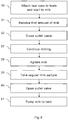
- Fig. 6 shows a flow chart for taking a regular milk sample from the milk in the milk receiver 1.
- the milking process of an animal starts at 30 by teat cups being attached to teats of the animal. Milk flows from the animal via the teat cups and milk tubes to the inlet portions 2 of the milk receiver 1.
- the milk entering the milk receiver 1 is untreated and stratifies into layers. Since the outlet valve device is open, the milk entering the milk receiver 1 flows directly out of the milk receiver 1, via the outlet portion, to the milk conduit 8.
- This first amount of milk from the milking process cleans the inner walls of the milk receiver 1 from milk residues from a previous milking process. If the inlet portions 2 are tangential, this cleaning effect will be further increased.
- the first amount of milk is at 31 collected in the milk conduit 8 in a position downstream of the outlet valve 17 of the milk receiver 1 but upstream of the milk pump 9.
- the milk pump 9 is not activated, because it is advantageous not to pump small quantities of milk - this is gentler for both the pump and the milk.
- the control unit 10 continuously receives information from the flow meters 4a about the milk flow to the milk receiver 1 and estimates the milk quantity supplied to the milk receiver 1.
- a predetermined first amount of milk which may e.g. be 500 ml
- the control unit 10 activates, at 32, the second pneumatic actuator 18 such that it moves the outlet valve 17 to the closed position. Milking continues at 37, and the milk is now collected in the milk receiver 1 instead of in the milk conduit 8.
- the control unit 10 continuously receives information from the milk level meter 4b, which may e.g. be a float, of the milk level in the milk receiver 1. At some point, preferably when the milk level is high enough to cover the agitation member 14, the control unit 10 at 38 activates the first pneumatic actuator 16 such that it performs a reciprocating swinging movement of the agitation member 14.
- the reciprocating swinging movement of the agitation member 14 provides a gentle but effective stirring process of the milk in the whole receiver 1. As a consequence, the stirring process results in a homogenous mixture of the different layers and substantially all included substances in the whole receiver 1.
- a regular milk sample is now, at 39, taken of the milk in the milk receiver 1.
- the regular milk sample is extracted, via the milk sample outlet 19, from the outlet portion 12 of the milk receiver 1.
- the regular milk sample may be directed to a test tube or the like, or directly to an analysis instrument. It is possible to instead take the regular milk sample during the final part of the milking process, before it has ended. In either case, it is not necessary to stop the swinging movement of the agitation member 14 before the regular milk sample is taken.
- the control unit 10 activates the second pneumatic actuator 18, at 40, such that it moves the outlet valve 17 to the open position.
- the milk flows out from the milk receiver 1 to the milk conduit 8.
- the control unit 10 starts, at 41, the milk pump 9 such that the milk in the milk conduit 8 is pumped to a main milk tank where it is mixed with milk from other milking stalls.
- the control unit 10 receives information from the milk level meter 4b indicating that the milk receiver is empty, the control unit 10 stops the activation of the milk pump.
- the outlet valve 17 is maintained in the open position such that any remaining milk residues are able to flow out from the milk receiver 1.
- the outlet valve 17 is then kept open until the control unit 10 closes it at 32 during the milking process of the next animal.
- Fig. 7 shows a flow chart for also taking a partial milk sample from the milk in the milk receiver 1.
- the milking process of a selected animal starts at 30 by teat cups being attached only to one or two selected teats of the animal. Milk flows from the selected teats via the teat cups and milk tubes to the inlet portions 2 of the milk receiver 1. Since the outlet valve device is open, the milk entering the milk receiver 1 flows substantially immediately out of the milk receiver 1, via the outlet portion, to the milk conduit 8.
- This first amount of milk from the milking process cleans the inner walls of the milk receiver 1 from milk residues from a previous milking process. If the inlet portions 2 are tangential, this cleaning effect will be further increased.
- the first amount of milk is collected in the milk conduit 8 in a position downstream of the outlet valve 17 of the milk receiver 1 but upstream of the milk pump 9.
- the control unit 10 receives information from the flow meters 4a about the milk flow to the milk receiver 1.
- the control unit 10 continuously receives information from the flow meters 4a about the milk flow to the milk receiver 1 and estimates the milk quantity supplied to the milk receiver 1.
- a predetermined first amount of milk which may e.g. be 500 ml
- the control unit 10 activates, at 32, the second pneumatic actuator 18 such that it moves the outlet valve 17 to the closed position.
- Milking of the selected teats continues at 33 until a second amount of milk (which may be either a predetermined amount or all the milk from the selected teats) has entered the milk receiver 1.
- the milk is now collected in the milk receiver 1 instead of in the milk conduit 8.
- the control unit 10 continuously receives information from the milk level meter 4b of the milk level in the milk receiver 1. At some point, preferably when the milk level is high enough to cover the agitation member 14, the control unit 10 at 34 activates the first pneumatic actuator 16 such that it provides a gentle but effective stirring process of the milk in the whole receiver 1.
- a partial milk sample is now, at 35, taken of the milk in the milk receiver 1.
- the partial milk sample is extracted, via the milk sample outlet 19, from the outlet portion 12 of the milk receiver 1.
- the partial milk sample may be directed to a test tube or the like, or directly to an analysis instrument. It is possible but not necessary to stop the swinging movement of the agitation member 14 before the partial milk sample is taken.
- teat cups are at 36 attached to the remaining teats of the animal and milking continues at 37. Milk flows from the remaining teats via the teat cups and milk tubes to the inlet portions 2 of the milk receiver 1. If the swinging movement of the agitation member 14 was stopped before the partial milk sample was taken, the control unit 10 at some point again at 38 activates the first pneumatic actuator 16 such that it provides a gentle but effective stirring process of the milk in the whole receiver 1. If the swinging movement of the agitation member 14 was not stopped before the partial milk sample was taken, agitation of the milk simply continues at 38.
- a regular milk sample is now, at 39, taken of the milk in the milk receiver 1.
- the regular milk sample is extracted, via the milk sample outlet 19, from the outlet portion 12 of the milk receiver 1.
- the regular milk sample may be directed to a test tube or the like, or directly to an analysis instrument. It is possible to instead take the regular milk sample during the final part of the milking process, before it has ended. In either case, it is not necessary to stop the swinging movement of the agitation member 14 before the milk sample is taken.
- the control unit 10 activates the second pneumatic actuator 18, at 40, such that it moves the outlet valve 17 to the open position.
- the milk flows out from the milk receiver 1 to the milk conduit 8.
- the control unit 10 starts, at 41, the milk pump 9 such that the milk in the milk conduit 8 is pumped to a main milk tank where it is mixed with milk from other milking stalls.
- the control unit 10 receives information from the milk level meter 4b indicating that the milk receiver is empty, the control unit 10 stops the activation of the milk pump.
- the outlet valve 17 is maintained in the open position such that any remaining milk residues are able to flow out from the milk receiver 1.
- the outlet valve 17 is then kept open until the control unit 10 closes it at 32 during the milking process of the next animal.
- Any kind of milk receiver 1 can be used, and agitation of the milk does not have to be done using a mechanical stirrer, but can take place in any conceivable way, e.g. by pumping the milk or supplying air to the receiver.
Landscapes
- Life Sciences & Earth Sciences (AREA)
- Animal Husbandry (AREA)
- Environmental Sciences (AREA)
- Sampling And Sample Adjustment (AREA)
Claims (15)
- Verfahren zum Entnehmen einer Probe aus Milch in einer Melkmaschine, umfassend Zitzenbecher, ein Milchaufnahmegefäß (1), in das ein Vakuum aus einer Vakuumzufuhr (5, 6) Milch aus den Zitzenbechern zieht, und eine Milchprobenentnahmeanordnung, die eine Vermischvorrichtung, die konfiguriert ist, um einen Rührvorgang der Milch in dem Milchaufnahmegefäß (1) bereitzustellen, eine Milchprobenvorrichtung, die konfiguriert ist, um eine Milchprobe aus der Milch in dem Milchaufnahmegefäß (1) zu extrahieren, und eine Auslassventilvorrichtung, die konfiguriert ist, um den Milchfluss aus dem Milchaufnahmegefäß (1) zu steuern, umfasst, wobei das Verfahren die folgenden Schritte umfasst:- Anbringen (30) von Zitzenbechern an den Zitzen eines Tieres und Starten des Melkens der Zitzen;- Aufnehmen (31) einer ersten Milchmenge in dem Milchaufnahmegefäß (1), während die Auslassventilvorrichtung offen gehalten wird;- Schließen (32) der Auslassventilvorrichtung;- Fortsetzen (37) des Aufnehmens von Milch in dem Milchaufnahmegefäß (1);- Vermischen (38) der Milch in dem Milchaufnahmegefäß (1) unter Verwendung der Vermischvorrichtung; und- Entnehmen (39) einer regelmäßigen Milchprobe aus der Milch in einem Auslassabschnitt (12) des Milchaufnahmegefäßes (1) mittels der Milchprobenvorrichtung; und- Öffnen (40) der Auslassventilvorrichtung, sodass die Milch in den Milchtank überführt (41) werden kann.
- Verfahren nach Anspruch 1, wobei das Verfahren den weiteren folgenden Schritt umfasst:- Sammeln wenigstens eines Teils der ersten Milchmenge in einer Milchleitung (8) in einer Position stromabwärts der Auslassventilvorrichtung des Milchaufnahmegeräßes (1) und stromaufwärts einer nicht aktivierten Milchpumpe (9).
- Verfahren nach Anspruch 1 oder 2, wobei das Verfahren den weiteren folgenden Schritt umfasst:- Aktivieren der Vermischvorrichtung sobald der Milchfüllstand in dem Milchaufnahmegefäß (1) einen vorgegebenen Füllstand erreicht.
- Verfahren nach Anspruch 3, wobei das Verfahren den weiteren folgenden Schritt umfasst:- Aktivieren der Vermischvorrichtung sobald der Milchfüllstand in dem Milchaufnahmegefäß (1) hoch genug ist, um das gesamte Vermischelement (14) zu bedecken.
- Verfahren nach einem der vorhergehenden Ansprüche, wobei das Verfahren den weiteren folgenden Schritt umfasst:- Offenhalten der Auslassventilvorrichtung, wenn das Milchaufnahmegefäß (1) von Milch aus einem Melkvorgang entleert wurde.
- Verfahren nach einem der vorhergehenden Ansprüche, wobei der Schritt des Anbringens (30) von Zitzenbechern an Zitzen eines Tieres und des Startens des Melkens der Zitzen für ein ausgewähltes Tier das Anbringen (30) von Zitzenbechern nur an eine oder zwei ausgewählte Zitzen und das Starten des Melkens der einen oder der zwei ausgewählten Zitzen umfasst, wobei das Verfahren die weiteren folgenden Schritte umfasst:- nach dem Schließen der Auslassventileinrichtung (32), Aufnehmen (33) einer zweiten Milchmenge in dem Milchaufnahmegefäß (1);- Vermischen (34) der Milch in dem Milchaufnahmegefäß (1) unter Verwendung der Vermischvorrichtung;- Entnehmen (35) einer Teilmilchprobe aus der Milch in einem Auslassabschnitt (12) des Milchaufnahmegefäßes (1) mittels der Milchprobenvorrichtung; und- nach dem Entnehmen (35) der Teilmilchprobe, Anbringen (36) von Zitzenbechern an den verbleibenden Zitzen des Tieres und Melken der verbleibenden Zitzen.
- Verfahren nach Anspruch 6, wobei das ausgewählte Tier ein Tier ist, für das eine Milchprobenanalyse einer in Verbindung mit einem vorherigen Melken entnommenen Milchprobe ein erhöhtes Risiko für eine Erkrankung bestimmt hat.
- Verfahren nach Anspruch 6, wobei das ausgewählte Tier ist ein Tier ist, für das eine Milchprobe von aus der einen oder den zwei ausgewählt Zitzen stammenden Probe für einen zuvor bestimmten Zeitraum nicht entnommen wurde.
- Verfahren nach einem der vorhergehenden Ansprüche, wobei die Milchprobenentnahmeanordnungen eine Steuereinheit (10) umfasst, die konfiguriert ist, um die Vermischvorrichtung, die Milchprobenvorrichtung und die Auslassventilvorrichtung zu steuern.
- Verfahren nach einem der vorhergehenden Ansprüche, wobei die Milchprobenvorrichtung einen Milchprobenentnahmeauslass (19) umfasst, der konfiguriert ist, um Milchproben aus der Milch in dem Auslassabschnitt (12) zu extrahieren.
- Verfahren nach einem der vorhergehenden Ansprüche, wobei die Milchprobenvorrichtung und die Auslassventilvorrichtung in einer Bodenstruktur (7) beinhaltet sind, die an einem Bodenabschnitt des Milchaufnahmegefäßes (1) montiert werden kann.
- Verfahren nach Anspruch 11, wobei die Bodenstruktur (7) mittels eines lösbaren Verbindungselements (21) an einem Bodenabschnitt des Milchaufnahmegefäßes (1) montiert ist.
- Verfahren nach Anspruch 11 oder 12, wobei die Bodenstruktur (7) einen Auslassabschnitt (12) des Milchaufnahmegefäßes (1) definiert, der sich auf einer niedrigeren Ebene als die verbleibenden Teile des Innenraums des Milchaufnahmegefäßes (1) befindet.
- Verfahren nach Anspruch 13, wobei der Auslassabschnitt (12) eine Auslassöffnung umfasst und dass die Auslassventilvorrichtung ein Auslassventil (17) umfasst, das in einer ersten Position die Auslassöffnung schließt und in einer zweiten Position die Auslassöffnung freilegt.
- Melkmaschine, umfassend Zitzenbecher, ein Milchaufnahmegefäß (1), in das das Vakuum aus einer Vakuumzufuhr (5, 6) Milch aus den Zitzenbechern zieht, und eine Milchprobenentnahmeanordnung, wobei die Milchprobenentnahmevorrichtung eine Vermischvorrichtung, die konfiguriert ist, um einen Rührvorgang der Milch in dem Milchaufnahmegefäß (1) bereitzustellen, eine Milchprobenvorrichtung, die konfiguriert ist, um eine Milchprobe aus der Milch in dem Milchaufnahmegefäß (1) zu extrahieren, und eine Auslassventilvorrichtung, die konfiguriert ist, um den Milchfluss aus dem Milchaufnahmegefäß (1) zu steuern, umfasst, wobei die Melkmaschine konfiguriert ist, um das Verfahren nach einem der Ansprüche 1-14 durchzuführen.
Applications Claiming Priority (2)
| Application Number | Priority Date | Filing Date | Title |
|---|---|---|---|
| SE1451667 | 2014-12-30 | ||
| PCT/SE2015/051347 WO2016108747A1 (en) | 2014-12-30 | 2015-12-15 | A method for sampling of milk in a milking machine and a milking machine |
Publications (2)
| Publication Number | Publication Date |
|---|---|
| EP3240397A1 EP3240397A1 (de) | 2017-11-08 |
| EP3240397B1 true EP3240397B1 (de) | 2020-04-15 |
Family
ID=55083454
Family Applications (1)
| Application Number | Title | Priority Date | Filing Date |
|---|---|---|---|
| EP15823209.0A Active EP3240397B1 (de) | 2014-12-30 | 2015-12-15 | Verfahren zur probenahme von milch in einer melkmaschine und melkmaschine |
Country Status (4)
| Country | Link |
|---|---|
| US (1) | US10721904B2 (de) |
| EP (1) | EP3240397B1 (de) |
| CA (1) | CA2972010C (de) |
| WO (1) | WO2016108747A1 (de) |
Families Citing this family (1)
| Publication number | Priority date | Publication date | Assignee | Title |
|---|---|---|---|---|
| US10800594B2 (en) * | 2017-10-31 | 2020-10-13 | Quality Mangement, Incorporated | Securable sampling port for an insulated container |
Family Cites Families (11)
| Publication number | Priority date | Publication date | Assignee | Title |
|---|---|---|---|---|
| NL9200582A (nl) * | 1992-03-30 | 1993-10-18 | Lely Nv C Van Der | Werkwijze en inrichting voor het automatisch melken van dieren. |
| US5632411A (en) | 1992-06-17 | 1997-05-27 | Dewvale Limited | Meter and a method for measuring quantity of a flowing liquid |
| SE520348C2 (sv) * | 2000-04-03 | 2003-07-01 | Delaval Holding Ab | Anordning och förfarande för provtagning av mjölk |
| SE522430C2 (sv) | 2001-06-27 | 2004-02-10 | Delaval Holding Ab | Förfarande och anordning för räkning av somatiska celler |
| SE530500C2 (sv) * | 2006-11-16 | 2008-06-24 | Delaval Holding Ab | Anordning och förfarande för provtagning av mjölk |
| SE531677C2 (sv) * | 2007-06-18 | 2009-06-30 | Delaval Holding Ab | Mjölkningssystem med provkanal |
| WO2009096888A1 (en) * | 2008-01-30 | 2009-08-06 | Delaval Holding Ab | Milking station arrangement for and method of obtaining a representative milking sample |
| SE532738C2 (sv) * | 2008-01-30 | 2010-03-30 | Delaval Holding Ab | Arrangemang och metod vid mjölkprovtagning vid mjölkning av ett djur |
| GB201021826D0 (en) * | 2010-12-21 | 2011-02-02 | Delaval Holding Ab | Milk sampling |
| US8701510B2 (en) * | 2010-12-28 | 2014-04-22 | Delaval Holding Ab | Smart milk sampler for VMS |
| WO2013032397A1 (en) | 2011-09-02 | 2013-03-07 | Delaval Holding Ab | A milk sampling device |
-
2015
- 2015-12-15 EP EP15823209.0A patent/EP3240397B1/de active Active
- 2015-12-15 US US15/540,922 patent/US10721904B2/en active Active
- 2015-12-15 CA CA2972010A patent/CA2972010C/en active Active
- 2015-12-15 WO PCT/SE2015/051347 patent/WO2016108747A1/en not_active Ceased
Non-Patent Citations (1)
| Title |
|---|
| None * |
Also Published As
| Publication number | Publication date |
|---|---|
| US10721904B2 (en) | 2020-07-28 |
| CA2972010A1 (en) | 2016-07-07 |
| CA2972010C (en) | 2023-04-04 |
| WO2016108747A1 (en) | 2016-07-07 |
| US20170347615A1 (en) | 2017-12-07 |
| EP3240397A1 (de) | 2017-11-08 |
Similar Documents
| Publication | Publication Date | Title |
|---|---|---|
| EP2654411B1 (de) | Entnahme von milchproben | |
| US9155281B2 (en) | Milking plant | |
| RU2744798C1 (ru) | Пробоотборное устройство для взятия репрезентативной пробы молока и способ отбора репрезентативных проб молока | |
| US20070181067A1 (en) | Milk conveyer device | |
| CN103648268B (zh) | 用于实现至少一次测量并且用于从挤奶机取得奶样品的设备 | |
| US20110120378A1 (en) | System and method for automatically obtaining a milk sample and performing cleaning | |
| EP3240397B1 (de) | Verfahren zur probenahme von milch in einer melkmaschine und melkmaschine | |
| EP3240398B1 (de) | Bodenstruktur für einen milchauffangbehälter | |
| WO2014158082A1 (en) | A milk sampling arrangement and a method for sampling of milk in a milk receiver | |
| NZ762087B2 (en) | Sampling apparatus for taking a representative milk sample and method for taking representative milk samples | |
| NZ618689B2 (en) | Device for carrying out at least one measurement and for taking milk samples from a milking machine |
Legal Events
| Date | Code | Title | Description |
|---|---|---|---|
| STAA | Information on the status of an ep patent application or granted ep patent |
Free format text: STATUS: THE INTERNATIONAL PUBLICATION HAS BEEN MADE |
|
| PUAI | Public reference made under article 153(3) epc to a published international application that has entered the european phase |
Free format text: ORIGINAL CODE: 0009012 |
|
| STAA | Information on the status of an ep patent application or granted ep patent |
Free format text: STATUS: REQUEST FOR EXAMINATION WAS MADE |
|
| 17P | Request for examination filed |
Effective date: 20170705 |
|
| AK | Designated contracting states |
Kind code of ref document: A1 Designated state(s): AL AT BE BG CH CY CZ DE DK EE ES FI FR GB GR HR HU IE IS IT LI LT LU LV MC MK MT NL NO PL PT RO RS SE SI SK SM TR |
|
| AX | Request for extension of the european patent |
Extension state: BA ME |
|
| DAV | Request for validation of the european patent (deleted) | ||
| DAX | Request for extension of the european patent (deleted) | ||
| GRAP | Despatch of communication of intention to grant a patent |
Free format text: ORIGINAL CODE: EPIDOSNIGR1 |
|
| STAA | Information on the status of an ep patent application or granted ep patent |
Free format text: STATUS: GRANT OF PATENT IS INTENDED |
|
| INTG | Intention to grant announced |
Effective date: 20191211 |
|
| GRAS | Grant fee paid |
Free format text: ORIGINAL CODE: EPIDOSNIGR3 |
|
| GRAA | (expected) grant |
Free format text: ORIGINAL CODE: 0009210 |
|
| STAA | Information on the status of an ep patent application or granted ep patent |
Free format text: STATUS: THE PATENT HAS BEEN GRANTED |
|
| AK | Designated contracting states |
Kind code of ref document: B1 Designated state(s): AL AT BE BG CH CY CZ DE DK EE ES FI FR GB GR HR HU IE IS IT LI LT LU LV MC MK MT NL NO PL PT RO RS SE SI SK SM TR |
|
| REG | Reference to a national code |
Ref country code: CH Ref legal event code: EP |
|
| REG | Reference to a national code |
Ref country code: DE Ref legal event code: R096 Ref document number: 602015050844 Country of ref document: DE |
|
| REG | Reference to a national code |
Ref country code: IE Ref legal event code: FG4D |
|
| REG | Reference to a national code |
Ref country code: AT Ref legal event code: REF Ref document number: 1256212 Country of ref document: AT Kind code of ref document: T Effective date: 20200515 |
|
| REG | Reference to a national code |
Ref country code: NL Ref legal event code: FP |
|
| REG | Reference to a national code |
Ref country code: LT Ref legal event code: MG4D |
|
| PG25 | Lapsed in a contracting state [announced via postgrant information from national office to epo] |
Ref country code: NO Free format text: LAPSE BECAUSE OF FAILURE TO SUBMIT A TRANSLATION OF THE DESCRIPTION OR TO PAY THE FEE WITHIN THE PRESCRIBED TIME-LIMIT Effective date: 20200715 Ref country code: GR Free format text: LAPSE BECAUSE OF FAILURE TO SUBMIT A TRANSLATION OF THE DESCRIPTION OR TO PAY THE FEE WITHIN THE PRESCRIBED TIME-LIMIT Effective date: 20200716 Ref country code: IS Free format text: LAPSE BECAUSE OF FAILURE TO SUBMIT A TRANSLATION OF THE DESCRIPTION OR TO PAY THE FEE WITHIN THE PRESCRIBED TIME-LIMIT Effective date: 20200815 Ref country code: SE Free format text: LAPSE BECAUSE OF FAILURE TO SUBMIT A TRANSLATION OF THE DESCRIPTION OR TO PAY THE FEE WITHIN THE PRESCRIBED TIME-LIMIT Effective date: 20200415 Ref country code: LT Free format text: LAPSE BECAUSE OF FAILURE TO SUBMIT A TRANSLATION OF THE DESCRIPTION OR TO PAY THE FEE WITHIN THE PRESCRIBED TIME-LIMIT Effective date: 20200415 Ref country code: FI Free format text: LAPSE BECAUSE OF FAILURE TO SUBMIT A TRANSLATION OF THE DESCRIPTION OR TO PAY THE FEE WITHIN THE PRESCRIBED TIME-LIMIT Effective date: 20200415 Ref country code: PT Free format text: LAPSE BECAUSE OF FAILURE TO SUBMIT A TRANSLATION OF THE DESCRIPTION OR TO PAY THE FEE WITHIN THE PRESCRIBED TIME-LIMIT Effective date: 20200817 |
|
| REG | Reference to a national code |
Ref country code: AT Ref legal event code: MK05 Ref document number: 1256212 Country of ref document: AT Kind code of ref document: T Effective date: 20200415 |
|
| PG25 | Lapsed in a contracting state [announced via postgrant information from national office to epo] |
Ref country code: BG Free format text: LAPSE BECAUSE OF FAILURE TO SUBMIT A TRANSLATION OF THE DESCRIPTION OR TO PAY THE FEE WITHIN THE PRESCRIBED TIME-LIMIT Effective date: 20200715 Ref country code: LV Free format text: LAPSE BECAUSE OF FAILURE TO SUBMIT A TRANSLATION OF THE DESCRIPTION OR TO PAY THE FEE WITHIN THE PRESCRIBED TIME-LIMIT Effective date: 20200415 Ref country code: RS Free format text: LAPSE BECAUSE OF FAILURE TO SUBMIT A TRANSLATION OF THE DESCRIPTION OR TO PAY THE FEE WITHIN THE PRESCRIBED TIME-LIMIT Effective date: 20200415 Ref country code: HR Free format text: LAPSE BECAUSE OF FAILURE TO SUBMIT A TRANSLATION OF THE DESCRIPTION OR TO PAY THE FEE WITHIN THE PRESCRIBED TIME-LIMIT Effective date: 20200415 |
|
| PG25 | Lapsed in a contracting state [announced via postgrant information from national office to epo] |
Ref country code: AL Free format text: LAPSE BECAUSE OF FAILURE TO SUBMIT A TRANSLATION OF THE DESCRIPTION OR TO PAY THE FEE WITHIN THE PRESCRIBED TIME-LIMIT Effective date: 20200415 |
|
| REG | Reference to a national code |
Ref country code: DE Ref legal event code: R097 Ref document number: 602015050844 Country of ref document: DE |
|
| PG25 | Lapsed in a contracting state [announced via postgrant information from national office to epo] |
Ref country code: CZ Free format text: LAPSE BECAUSE OF FAILURE TO SUBMIT A TRANSLATION OF THE DESCRIPTION OR TO PAY THE FEE WITHIN THE PRESCRIBED TIME-LIMIT Effective date: 20200415 Ref country code: AT Free format text: LAPSE BECAUSE OF FAILURE TO SUBMIT A TRANSLATION OF THE DESCRIPTION OR TO PAY THE FEE WITHIN THE PRESCRIBED TIME-LIMIT Effective date: 20200415 Ref country code: RO Free format text: LAPSE BECAUSE OF FAILURE TO SUBMIT A TRANSLATION OF THE DESCRIPTION OR TO PAY THE FEE WITHIN THE PRESCRIBED TIME-LIMIT Effective date: 20200415 Ref country code: DK Free format text: LAPSE BECAUSE OF FAILURE TO SUBMIT A TRANSLATION OF THE DESCRIPTION OR TO PAY THE FEE WITHIN THE PRESCRIBED TIME-LIMIT Effective date: 20200415 Ref country code: EE Free format text: LAPSE BECAUSE OF FAILURE TO SUBMIT A TRANSLATION OF THE DESCRIPTION OR TO PAY THE FEE WITHIN THE PRESCRIBED TIME-LIMIT Effective date: 20200415 Ref country code: SM Free format text: LAPSE BECAUSE OF FAILURE TO SUBMIT A TRANSLATION OF THE DESCRIPTION OR TO PAY THE FEE WITHIN THE PRESCRIBED TIME-LIMIT Effective date: 20200415 Ref country code: ES Free format text: LAPSE BECAUSE OF FAILURE TO SUBMIT A TRANSLATION OF THE DESCRIPTION OR TO PAY THE FEE WITHIN THE PRESCRIBED TIME-LIMIT Effective date: 20200415 |
|
| PLBE | No opposition filed within time limit |
Free format text: ORIGINAL CODE: 0009261 |
|
| STAA | Information on the status of an ep patent application or granted ep patent |
Free format text: STATUS: NO OPPOSITION FILED WITHIN TIME LIMIT |
|
| PG25 | Lapsed in a contracting state [announced via postgrant information from national office to epo] |
Ref country code: SK Free format text: LAPSE BECAUSE OF FAILURE TO SUBMIT A TRANSLATION OF THE DESCRIPTION OR TO PAY THE FEE WITHIN THE PRESCRIBED TIME-LIMIT Effective date: 20200415 Ref country code: PL Free format text: LAPSE BECAUSE OF FAILURE TO SUBMIT A TRANSLATION OF THE DESCRIPTION OR TO PAY THE FEE WITHIN THE PRESCRIBED TIME-LIMIT Effective date: 20200415 |
|
| 26N | No opposition filed |
Effective date: 20210118 |
|
| PG25 | Lapsed in a contracting state [announced via postgrant information from national office to epo] |
Ref country code: SI Free format text: LAPSE BECAUSE OF FAILURE TO SUBMIT A TRANSLATION OF THE DESCRIPTION OR TO PAY THE FEE WITHIN THE PRESCRIBED TIME-LIMIT Effective date: 20200415 |
|
| REG | Reference to a national code |
Ref country code: CH Ref legal event code: PL |
|
| PG25 | Lapsed in a contracting state [announced via postgrant information from national office to epo] |
Ref country code: MC Free format text: LAPSE BECAUSE OF FAILURE TO SUBMIT A TRANSLATION OF THE DESCRIPTION OR TO PAY THE FEE WITHIN THE PRESCRIBED TIME-LIMIT Effective date: 20200415 |
|
| REG | Reference to a national code |
Ref country code: BE Ref legal event code: MM Effective date: 20201231 |
|
| PG25 | Lapsed in a contracting state [announced via postgrant information from national office to epo] |
Ref country code: LU Free format text: LAPSE BECAUSE OF NON-PAYMENT OF DUE FEES Effective date: 20201215 |
|
| PG25 | Lapsed in a contracting state [announced via postgrant information from national office to epo] |
Ref country code: CH Free format text: LAPSE BECAUSE OF NON-PAYMENT OF DUE FEES Effective date: 20201231 Ref country code: LI Free format text: LAPSE BECAUSE OF NON-PAYMENT OF DUE FEES Effective date: 20201231 |
|
| PG25 | Lapsed in a contracting state [announced via postgrant information from national office to epo] |
Ref country code: TR Free format text: LAPSE BECAUSE OF FAILURE TO SUBMIT A TRANSLATION OF THE DESCRIPTION OR TO PAY THE FEE WITHIN THE PRESCRIBED TIME-LIMIT Effective date: 20200415 Ref country code: MT Free format text: LAPSE BECAUSE OF FAILURE TO SUBMIT A TRANSLATION OF THE DESCRIPTION OR TO PAY THE FEE WITHIN THE PRESCRIBED TIME-LIMIT Effective date: 20200415 Ref country code: CY Free format text: LAPSE BECAUSE OF FAILURE TO SUBMIT A TRANSLATION OF THE DESCRIPTION OR TO PAY THE FEE WITHIN THE PRESCRIBED TIME-LIMIT Effective date: 20200415 |
|
| PG25 | Lapsed in a contracting state [announced via postgrant information from national office to epo] |
Ref country code: MK Free format text: LAPSE BECAUSE OF FAILURE TO SUBMIT A TRANSLATION OF THE DESCRIPTION OR TO PAY THE FEE WITHIN THE PRESCRIBED TIME-LIMIT Effective date: 20200415 |
|
| PG25 | Lapsed in a contracting state [announced via postgrant information from national office to epo] |
Ref country code: BE Free format text: LAPSE BECAUSE OF NON-PAYMENT OF DUE FEES Effective date: 20201231 |
|
| REG | Reference to a national code |
Ref country code: FR Ref legal event code: PLFP Year of fee payment: 8 |
|
| PGFP | Annual fee paid to national office [announced via postgrant information from national office to epo] |
Ref country code: NL Payment date: 20251112 Year of fee payment: 11 |
|
| PGFP | Annual fee paid to national office [announced via postgrant information from national office to epo] |
Ref country code: DE Payment date: 20251104 Year of fee payment: 11 |
|
| PGFP | Annual fee paid to national office [announced via postgrant information from national office to epo] |
Ref country code: GB Payment date: 20251114 Year of fee payment: 11 |
|
| PGFP | Annual fee paid to national office [announced via postgrant information from national office to epo] |
Ref country code: IT Payment date: 20251121 Year of fee payment: 11 |
|
| PGFP | Annual fee paid to national office [announced via postgrant information from national office to epo] |
Ref country code: FR Payment date: 20251117 Year of fee payment: 11 |
|
| PGFP | Annual fee paid to national office [announced via postgrant information from national office to epo] |
Ref country code: IE Payment date: 20251111 Year of fee payment: 11 |