EP3239924B1 - Segmentierungen von multikomponentengefässen - Google Patents
Segmentierungen von multikomponentengefässen Download PDFInfo
- Publication number
- EP3239924B1 EP3239924B1 EP17171740.8A EP17171740A EP3239924B1 EP 3239924 B1 EP3239924 B1 EP 3239924B1 EP 17171740 A EP17171740 A EP 17171740A EP 3239924 B1 EP3239924 B1 EP 3239924B1
- Authority
- EP
- European Patent Office
- Prior art keywords
- anatomical structure
- segmentation
- outer boundary
- lumen
- intensity values
- Prior art date
- Legal status (The legal status is an assumption and is not a legal conclusion. Google has not performed a legal analysis and makes no representation as to the accuracy of the status listed.)
- Expired - Lifetime
Links
Images

Classifications
-
- G—PHYSICS
- G06—COMPUTING OR CALCULATING; COUNTING
- G06T—IMAGE DATA PROCESSING OR GENERATION, IN GENERAL
- G06T7/00—Image analysis
- G06T7/10—Segmentation; Edge detection
- G06T7/149—Segmentation; Edge detection involving deformable models, e.g. active contour models
-
- G—PHYSICS
- G06—COMPUTING OR CALCULATING; COUNTING
- G06T—IMAGE DATA PROCESSING OR GENERATION, IN GENERAL
- G06T7/00—Image analysis
- G06T7/10—Segmentation; Edge detection
- G06T7/12—Edge-based segmentation
-
- G—PHYSICS
- G06—COMPUTING OR CALCULATING; COUNTING
- G06T—IMAGE DATA PROCESSING OR GENERATION, IN GENERAL
- G06T2207/00—Indexing scheme for image analysis or image enhancement
- G06T2207/10—Image acquisition modality
- G06T2207/10072—Tomographic images
- G06T2207/10088—Magnetic resonance imaging [MRI]
-
- G—PHYSICS
- G06—COMPUTING OR CALCULATING; COUNTING
- G06T—IMAGE DATA PROCESSING OR GENERATION, IN GENERAL
- G06T2207/00—Indexing scheme for image analysis or image enhancement
- G06T2207/20—Special algorithmic details
- G06T2207/20112—Image segmentation details
- G06T2207/20116—Active contour; Active surface; Snakes
-
- G—PHYSICS
- G06—COMPUTING OR CALCULATING; COUNTING
- G06T—IMAGE DATA PROCESSING OR GENERATION, IN GENERAL
- G06T2207/00—Indexing scheme for image analysis or image enhancement
- G06T2207/30—Subject of image; Context of image processing
- G06T2207/30004—Biomedical image processing
- G06T2207/30016—Brain
-
- G—PHYSICS
- G06—COMPUTING OR CALCULATING; COUNTING
- G06T—IMAGE DATA PROCESSING OR GENERATION, IN GENERAL
- G06T2207/00—Indexing scheme for image analysis or image enhancement
- G06T2207/30—Subject of image; Context of image processing
- G06T2207/30004—Biomedical image processing
- G06T2207/30101—Blood vessel; Artery; Vein; Vascular
Definitions
- the present invention relates to the segmentation of structures in digitized scans acquired by a radiological method such as Computed Tomography Angiography (CTA). More specifically, the present invention relates to the segmentation of anatomical structures such as blood vessels into their constituents for subsequent visualization and measurement.
- CTA Computed Tomography Angiography
- Segmentation of anatomical structures such as a blood vessel finds particular application in many areas of cardiovascular medicine, in which it is required to visualize a diseased vessel, to determine which components it consists of (e.g. lumen, thrombus, wall, calcifications, plaques) and to accurately derive parameters for each of these components (shape, size, diameter, area, volume, etc.). While a blood vessel without pathological findings can be assumed to consist of a lumen (the perfused part) and a healthy wall (the unperfused part), a pathological blood vessel usually shows additional anatomical structures. The abdominal aorta will be used as an example.
- AAA African aortic aneurysm
- Image-gradient-based approaches often fail because strong responses from neighboring objects, such as the spine and lumen, distract the method from finding the correct boundary. Threshold-based approaches are also prone to fail, since the same intensity value is found inside the thrombus and in the neighboring structures.
- the described segmentation method uses specific image features derived from a pre-processing step (threshold, morphological operations, and image gradient).
- threshold threshold
- morphological operations and image gradient
- the reported results do not seem sufficiently accurate.
- This and other of the earlier proposed methods to segment vessel components other than the lumen often fail due to the fact that conventional segmentation approaches do not take prior knowledge of the potential shapes and appearances (pixel intensities) of the vessel and its surroundings into account.
- These described problems appear also in the segmentation of other anatomical structures, such as the brain or the liver.
- a method of segmenting a three-dimensional digital representation of an anatomical structure comprises the steps defined in claim 1.
- the proposed method has the advantage that the segmentation of the outer boundary of the anatomical structure is not disturbed by e.g. lesions in the specified volume, caused by strongly differing intensity values of such lesions as compared with those of the healthy anatomical structure.
- These disturbing anatomical structures are relatively easily identified by verification of two conditions.
- the first condition concerns the spatial relationship of the outer boundary of the wall with respect to the lumen outer boundary.
- the wall outer boundary encloses the lumen outer boundary and is contained within a limited volume.
- the presence of the wall of the blood vessel may be assumed with a sufficiently high probability within a certain radial distance from the lumen outer boundary.
- the specified volume is determined by through determination of an envelope of the anatomical structure.
- the envelope may be determined in a generous manner to make sure that the entire outer boundary of the anatomical structure is enclosed in the envelope.
- the second condition helping in determining disturbing anatomical structures within the region of the blood vessel situated between the lumen outer boundary and the wall outer boundary concerns the range of the encountered intensity values.
- the disturbing anatomical structures may show intensity values in a scan of a radiology method, e.g. CTA, that strongly differ from the intensity values of a healthy wall.
- CTA radiology method
- the combination of the two conditions yields a reliable indicator for regions around the lumen outer boundary of a blood vessel that are actually disturbing anatomical structures.
- the temporary replacement of their intensity values with intensity values that correspond to those of a healthy blood vessel wall eliminates their strong influence on any method and/or algorithm used for the segmentation of the outer boundary of the wall.
- the disturbing anatomical structures are therefore regarded, during the segmentation of the wall outer boundary, as a part of the wall of the blood vessel. After the segmentation has been done, those intensity values that were replaced may be restored in order to reflect the disturbing anatomical structures between the lumen outer boundary and the wall outer boundary and to perform a segmentation on these disturbing anatomical structures.
- the specified volume is determined by a boundary layer surrounding the anatomical structure.
- Some anatomical structures are located within another anatomical structure surrounding the former.
- the boundary layer that is defined by the surrounding anatomical structure can also be used as a boundary for the specified volume. This is advantageous if the surrounding anatomical structure can be easily identified because of e.g. a typical range of intensity values.
- the substitute intensity value is automatically obtained by evaluation of intensity statistics in a specified volume, e.g. a shell around the segmented outer lumen boundary in the particular case of a blood vessel. This may be achieved, for example, by, among others, determining the mean or the most frequently occurring pixel value.
- the automatic determination of the substitute intensity value that is representative of a healthy wall reduces user interaction. The method becomes faster and more reproducible, for example for comparative clinical trials or long-term analysis.
- lesions in the specified volume are individually segmented subsequent to the restoration.
- disturbing anatomical structures within the anatomical structure to be segmented which are not necessarily pathological, can also be treated in this manner.
- Performing this step after the restoration of the intensity values, which had been previously replaced ensures that a proper segmentation of lesions within the specified volume is possible.
- the medical practitioner will be mostly interested in the anatomical structures within this region. Therefore, in the particular case of a blood vessel, limiting the volume of interest (VOI) to a hollow cylinder-like shape defined by the lumen outer boundary and the wall outer boundary available from the preceding segmentation steps facilitates the task of segmenting structures in this region of the blood vessel.
- these anatomical structures may be calcifications. Calcifications disturb the segmentation of the wall outer boundary of the blood vessel very strongly. Fortunately, the intensity values of calcifications are always in a certain, rather limited range (actually above a certain value). They can therefore be easily identified and replaced by values that are more equal to those of a healthy wall. Still, the anatomical structures may also be plaques in the particular case of a blood vessel. For certain radiology methods, certain plaque types may be the disturbing factor. In particular, certain plaque types appear brighter than healthy wall in Magnetic Resonance Imaging (MRI). Accordingly, plaques may be dealt with in a similar manner as calcifications.
- MRI Magnetic Resonance Imaging
- the digital representation is obtained from a radiology method.
- Radiology methods allow non-invasive acquisition of data from the interior of the body of a patient. Furthermore, their resolution may be sufficiently fine for the acquisition of structures within the anatomical structure.
- the radiology method is one of Computed Tomography Angiography (CTA) or Magnetic Resonance Imaging (MRI).
- CTA and MRI each have attributes that may make the one or the other more suitable for use on certain patients.
- CTA is more widely available, faster, and has a better spatial resolution than MRI.
- the last advantage is especially important for visualizing calcification.
- MRI on the other hand, can visualize an arterial lumen without contrast agents, although contrast agents may be used for enhanced contrast, as well. Furthermore, MRI does not use ionizing radiation.
- the anatomical structure is one of a blood vessel, a brain or a liver.
- the lumen is segmented first. Once the size of the blood vessel has been determined, the specified volume, in which replacement of intensity values is to be performed, can be determined, e.g. based on the diameter of the lumen indicating a more or less thick blood vessel.
- the brain is also well suited for the method according to the invention, since the skull provides a natural, easily detectable boundary for the specified volume. If the organ to be segmented is the liver, the boundary of the specified volume around the liver can be determined by e.g. consulting a different radiology method first and incorporating the result in the method of the present invention.
- a Computer Program Product for segmenting a three-dimensional digital representation of an anatomical structure is performed.
- the Computer Program Product performs the steps defined in claim 7.
- the proposed Computer Program Product has the advantage that the segmentation of the outer boundary of the anatomical structure is not disturbed by any lesions inside the region of the anatomical structure that is delineated by the specified volume, caused by the strongly differing intensity values of these structures compared with those of the anatomical structure.
- These lesions or disturbing anatomical structures are relatively easily identified by verification of two conditions.
- the first condition concerns the spatial relationship of the wall outer boundary with respect to the lumen outer boundary.
- the outer boundary encloses the lumen outer boundary and is contained within a limited volume.
- the presence of the wall of the blood vessel may be assumed with a sufficiently high probability within a certain radial distance from the lumen outer boundary.
- the specified volume is determined by through determination of an envelope of the anatomical structure.
- the envelope may be determined in a generous manner to make sure that the entire outer boundary of the anatomical structure is enclosed in the envelope.
- the second condition helping in determining disturbing anatomical structures within the blood vessel wall concerns the range of the encountered intensity values.
- the disturbing anatomical structures may show intensity values in a scan of a radiology method, e.g.
- a Computer Program Product is adapted to instruct a processor to perform the steps defined by the Computer Program Product in order eventually to obtain a representation of the segmented components of the anatomical structure in a memory connected to the processor.
- the specified volume is determined by a boundary layer surrounding the anatomical structure.
- Some anatomical structures are located within another anatomical structure surrounding the former.
- the boundary layer that is defined by the surrounding anatomical structure can also be used as a boundary for the specified volume. This is advantageous if the surrounding anatomical structure can be easily identified because of e.g. a typical range of intensity values.
- the substitute intensity value is automatically obtained by evaluation of intensity statistics in the specified volume. This can be achieved by determining the mean or the most frequently occurring pixel value, among other means.
- the automatic determination of the substitute intensity value that is representative of a healthy wall reduces user interaction. The method becomes faster and more reproducible, for example for comparative studies or long-term analysis.
- lesions in the specified volume are individually segmented. Performing this step after the restoration of the intensity values that had been replaced ensures that a proper segmentation of the lesions within the specified volume is possible.
- the medical practitioner will be mostly interested in the anatomical structures within this region of the blood vessel. Therefore, in the particular case of blood vessel, limiting the volume of interest (VOI) to a hollow cylinder defined by the lumen outer boundary and the wall outer boundary available from the preceding segmentation steps facilitates the task of segmenting structures within the region that the medical practitioner is interested in.
- the anatomical structures may be calcifications. Calcifications disturb the segmentation of the outer boundary very strongly.
- the intensity values of calcifications are always in a certain, rather limited range (actually above a certain value). They can therefore be easily identified and replaced by values that are more equal to those of the thrombus.
- the anatomical structures may be plaques in the particular case of a blood vessel.
- certain plaque types may be the disturbing factor.
- certain plaque types appear brighter than healthy wall in Magnetic Resonance Imaging (MRI). Accordingly, plaques may be dealt with in a similar manner as calcifications.
- MRI Magnetic Resonance Imaging
- the three-dimensional digital representation is obtained from a radiology method.
- Radiology methods allow non-invasive acquisition of data from the interior of the body of a patient. Furthermore, their resolution may be sufficiently fine for the acquisition of structures within the anatomical structure.
- the radiology method is one of Computed Tomography Angiography (CTA) or Magnetic Resonance Imaging (MRI).
- CTA and MRI each have attributes that may make the one or the other more desirable for application to certain patients.
- CTA is more widely available, faster, and has a better spatial resolution than MRI.
- the last advantage is especially important for visualizing calcification.
- MRI on the other hand, can visualize an arterial lumen without contrast agents. Furthermore, MRI does not use ionizing radiation.
- the anatomical structure is one of a blood vessel, a brain or a liver.
- the lumen is segmented first. Once the size of the blood vessel has been determined, the specified volume, in which replacement of intensity values is to be performed, can be determined, e.g. based on the diameter of the lumen indicating a more or less thick blood vessel.
- the brain is also well suited for the method according to the invention, since the skull provides a natural, easily detectable boundary for the specified volume. If the organ to be segmented is the liver, the boundary of the specified volume around the liver can be determined by e.g. consulting a different radiology method first and incorporating the result in the Computer Program Product of the present invention.
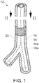
- Fig. 1 shows a blood vessel, more particularly a bifurcation of a blood vessel.
- the blood vessel 12 comprises a lumen 14 and a wall 16.
- the lumen 14 is the perfused part of the blood vessel, e.g. the part in which the blood flows.
- the lumen 14 is delineated by a lumen outer boundary 14a.
- a wall outer boundary 16a delineates the blood vessel against surrounding tissue.
- the upper half of wall 16 is shown only partly in order to make the lumen 14 better visible.
- a centerline 24 is calculated during execution of the method. Centerline 24 acts as an auxiliary tool during the execution of the method and provides an axis of reference for subsequent operations.
- the centerline can be determined between two user-defined or automatically determined points, a starting point and an end point.
- the centerline may be composed of two branches. It should be noted that the centerline, despite its name, does not necessarily have to be central to the lumen or located inside it, since the subsequent algorithms (e.g. the lumen outer boundary segmentation algorithm) using the centerline as an initialization are sufficiently robust.
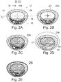
- Fig. 2A shows an axial section of blood vessel 12 along slice plane II-II.
- different anatomical structures are represented within the region bounded by the lumen outer boundary 14a and the wall outer boundary 16a. These anatomical structures are calcifications 17, a thrombus 18, and plaques 19.
- Centerline 24 is represented as a cross in dot-and-dash-style. It can be assumed to be located near the center of gravity of the lumen outer boundary 14a.
- This Fig. 2A represents an initial state of the three-dimensional representation of the blood vessel 12. Centerline 24 has been calculated already.
- FIG. 2B A next state of the three-dimensional representation of blood vessel 12 is shown in Fig. 2B .
- An initial tube-like three-dimensional Active Object (3DAO) 26a is placed along the centerline.
- 3D Active Objects sometimes also called 3D Deformable Models, are a technique for fitting surfaces to volumetric data. They are termed "physically based” since they are formulated in terms of lagrangian equations of motion and thus can be made dynamic to realistically simulate the behavior of physical objects.
- the surface is discretized using finite elements and the fitting of the surface to the data is accomplished through the minimalization of an energy functional describing the deformation energy of the surface.
- 3D Deformable Models have been applied to the segmentation of medical images volumes by placing a closed surface inside a region to be segmented and applying image forces to the surface on the basis of gradient information contained in the intensity distribution, allowing the surface to expand and conform to the region of interest.
- These types of models have the desirable properties of being able to assume complex free-form shapes and having an intuitive means of fitting the data by considering each data point as a user-applied point force on the surface.
- the polygon 26a represents a cross-section through a tube-like 3DAO placed along the centerline 24. The initial 3DAO is automatically deformed to the boundary of the lumen.
- Fig. 2C shows the result of the automatic deformation of the lumen 3DAO 26b, which closely approximates the lumen outer boundary 14a delineating the lumen 14 against the wall 16, calcifications 17, thrombus 18, and plaques 19.
- the final lumen 3DAO 26b is represented as a polygon having only eight vertices for reasons of clarity. In reality, much smaller vertices are used, so that the lumen boundary is accurately delineated.
- the cross-section of lumen 3DAO 26b could have an arbitrary geometrical shape, having in particular more vertices to approximate the lumen boundary more closely.
- the cross-section of the lumen 3DAO 26b is not necessarily constant along its longitudinal axis, but may vary as the lumen boundary varies.
- Fig. 2D the replacement of pixel intensities within a specified volume around the lumen is represented.
- the method assumes a high probability that the wall outer boundary of the blood vessel will be encountered within a certain distance from the lumen 3DAO 26b.
- the distance from the lumen 3DAO 26b up to which the presence of the blood vessel wall is assumed by the wall outer boundary segmenting method is depicted as an ellipse shown as a dashed line in Fig. 2D .
- Calcifications 17, a thrombus 18, and plaques 19 are contained in the ring defined by the lumen 3DAO 26b and the dashed ellipse marking the maximum distance from the segmented lumen.
- objects are assigned intensity values that are equal or close to the intensity values of the wall 16, which is implied by the same shade of grey in Fig. 2D .
- the lumen 3DAO 26b is used to initialized a wall outer boundary 3DAO 28.
- This wall outer boundary 3DAO 28 is deformed in a similar manner as described above. However, the deformation process is possibly being governed by a different stop criterion, if need be.
- Fig. 2E The final result of the deformation applied to the outer boundary 3DAO 28 is depicted in Fig. 2E .
- calcifications 17, the thrombus 18, and plaques 19 have been restored with their original pixel intensities, implied by the differing shades of grey corresponding to those in Figs. 2A - 2C .
- Their segmentation can now be achieved by applying a segmentation algorithm to the volume of interest, which is delimited by the lumen 3DAO 26b and the wall outer boundary 3DAO 28.
- This segmentation algorithm for the anatomical structures in the region of the blood vessel between lumen 3DAO 26b and the outer boundary 3DAO may be chosen and parameterized so as to perform a rather meticulous, or pedantic, segmentation. This is possible because the evaluation volume is limited. Furthermore, the pixel intensities within the limited volume of interest are distinctive for a certain anatomical structure, such as healthy wall 16, calcifications 17, thrombus 18, and plaques 19. Therefore, several clusters of intensity values in an intensity histogram may be expected to occur, with each cluster referring to the intensity values caused by a certain anatomical structure.
- Fig. 3 is a flowchart of a method according to the invention.
- Rhomboids represent data that is either an input to the method or an intermediate result. Rectangles represent operations performed on the data.
- One of the inputs of the method is a data set 30 (SCAN) that contains a three-dimensional representation of a part of a body, e.g. the abdomen.
- This data set can be obtained either directly from an appropriate acquisition device, such as a Computed Tomography Angiograph, or reproduced from a digital storage device.
- the data set contains a three-dimensional spatial distribution of intensities of the abdomen, for example, wherein these intensities reflect a certain physical property of a certain location within the body.
- a common physical property is the so-called Hounsfield value, which describes the absorption coefficient of the body at a certain location with respect to electromagnetic radiation in the X-ray range. Other physical properties may be detected by magnetic resonance imaging (MRI).
- MRI magnetic resonance imaging
- SP/EP start point and an end point 31
- SP/EP start point and an end point 31
- the start point and the end point may be user selected or determined automatically.
- CI chunk image generator
- VOI volume of interest
- the volume of interest 33 is usually a subset of the three-dimensional data set 30, so that unnecessary operations on parts of the data set that are of no or little interest are avoided.
- the volume of interest acts as an input parameter to several evaluation algorithms.
- One of these evaluation algorithms is the centerline determination 34 (CNTLN) between a start point and an end point 31.
- the determination of the centerline is based, for example, on the determination of the centers of gravity of subsequent cross-sections through the lumen. Connecting the centers of gravity then yields the centerline. It is also possible to determine the centerline as a least-cost route from the start point to the end point. Once the centerline has been determined, it is used as an initial guess for an initial surface 35 (IS) from which a 3D Active Object is to be developed by deformation.
- IS initial surface 35
- the deformation of this initial surface 37 is performed by a lumen surface deformation algorithm 36 (LSDEF).
- LDEF lumen surface deformation algorithm
- Such an algorithm may be, for example, threshold-based, which means that the vertex of the 3DAO is pushed outwards (i. e. according to a normal vector of the 3DAO at the locations of the considered vertex) as long as the intensity value at the vertex indicates that the vertex is still situated inside the lumen.
- This can be achieved by applying lower and upper thresholds defining the intensity interval of a typical vessel inside the lumen. As soon as the intensity value encountered at the vertex is outside this intensity interval, the vertex is pushed inside again.
- the algorithm also implements a stop criterion to indicate when the deformed surface sufficiently resembles the actual lumen of the blood vessel.
- the 3DAO eventually retained as the representation of the lumen is called the lumen surface 37 (LS).
- the region around the determined lumen surface 37 is modified in that intensity values that most probably do not refer to a healthy blood vessel wall are replaced with intensity values that correspond to those of a healthy blood vessel wall.
- This replacement step 38 (REPL) is carried out in a region around the lumen surface 37 having the approximate shape of a hollow cylinder along the centerline. The effective distance of this replacement action depends on the size and the state of health of the blood vessel.
- wall surface deformation step 39 A wall surface 3DAO is initialized with the lumen surface 3DAO found in step 37.
- Wall segmentation is a complex problem, and a deformable model of simple forces based on image intensity thresholds would not provide sufficiently better results.
- a pattern classification approach is used for grey value modeling, namely the k-nearest neighbors (KNN) algorithm.
- KNN k-nearest neighbors
- a cell corresponds to the k "neighbors" (or closest training points) of a given feature point.
- the posterior probability of the feature point belonging to a given class is determined by the density of training points in the cell: P ⁇ j
- y k j k .
- k j is the number of points belonging to class ⁇ j among the k (spatially) nearest neighbors of the given feature point y.
- the point is then assigned to the class with highest probability.
- Possible classes ⁇ j include "inside the object” (i.e. within the outer boundary of the wall), "outside the object” and at the "object boundary”.
- a vertex is either pushed outwards in case of a classification as "inside the object”, pushed inwards in case of a classification as “outside the object”, or maintained at its current location in case of a classification as "object boundary”.
- the stop criterion is met, if all, or at least a majority, of the vertices are located on the object boundary.
- the previous replacement step 38 reports the wall surface deformation to step 39 in that no disturbing anatomical structures influence the classification of a vertex.
- the final result of the wall surface deformation step 39 is written to a wall surface data structure 40 (WS), which is a 3D Active Object.
- RSTR restoration step 41
- the intensity replacements that have been performed during replacement step 38 are revoked. This restores the original intensity values so that a segmentation of the blood vessel wall and the anatomical structures contained therein can be performed.
- the invention may be applied to the segmentation of brain tissue in a 3D scan in order to separate lesions such as tumors in the brain.
- Healthy brain tissue usually has a rather uniform pixel intensity/Hounsfield value. Lesions, however, may have a different value.
- Segmentation of the healthy brain tissue e.g. using 3D Active Objects and/or deformable models, may be less optimal when the lesions are not temporarily replaced by an intensity similar to that of healthy brain tissue.
- the boundary for replacement could be the skull (which has a very high intensity and is therefore easily detected).
- Liver segmentation is another application of the present invention. Replacement of intensity values is performed on presumptive lesions (tumors) in the liver before segmentation of the complete liver from a 3D abdominal CT. As liver tissue is rather uniform in a CT representation, lesions may have a different intensity and/or Hounsfield value. However, defining the boundary for the intensity replacement may be a bit more difficult for the liver.
- the method and the Computer Program Product according to the invention may also be applied to several smaller organs in the body. Furthermore, it is conceivable to use the invention in a method for segmenting CT angiography scans of organs including the internal blood vessel.
- the lumens of the blood vessels themselves can be segmented, which is fairly easily done by thresholding.
- the detected lumen can then be replaced by e.g. the mean value of the surrounding tissue, and the complete organs can be segmented with more advanced techniques such as 3D Active Objects.
- the method can be performed using a workstation arranged to receive image data from a medical imaging and arranged to perform the method.
- An advantageous manner in which the invention may be worked includes the installation of the computer program product on the workstation for the performance of the method.
Landscapes
- Engineering & Computer Science (AREA)
- Computer Vision & Pattern Recognition (AREA)
- Physics & Mathematics (AREA)
- General Physics & Mathematics (AREA)
- Theoretical Computer Science (AREA)
- Software Systems (AREA)
- Apparatus For Radiation Diagnosis (AREA)
- Magnetic Resonance Imaging Apparatus (AREA)
- Image Processing (AREA)
- Processing Or Creating Images (AREA)
Claims (7)
- Computerimplementiertes Verfahren zur Segmentierung einer dreidimensionalen digitalen Darstellung einer anatomischen Struktur, wobei das Verfahren umfasst:- Segmentierung einer Außengrenze der anatomischen Struktur; dadurch gekennzeichnet, dass es zudem umfasst:- vorübergehendes Ersetzen von Intensitätswerten, die erheblich von denen der anatomischen Struktur abweichen, vor der Segmentierung der Außengrenze und in einem spezifizierten Volumen durch einen Ersatzintensitätswert, der für die anatomische Struktur repräsentativ ist, wobei das spezifizierte Volumen, in dem Ersetzen von Intensitätswerten durchgeführt werden soll, als eine Hülle der anatomischen Struktur bestimmt wird, wobei die Hülle basierend auf einer Grenzschicht einer anderen anatomischen Struktur definiert wird, die die zu segmentierende anatomische Struktur umgibt;- Wiederherstellung der signifikant abweichenden Intensitätswerte, sobald die Segmentierung der Außengrenze abgeschlossen ist.
- Verfahren nach Anspruch 1, wobei der Ersatzintensitätswert automatisch durch Auswertung von Intensitätsstatistiken in dem spezifizierten Volumen erhalten wird.
- Verfahren nach Anspruch 1 oder 2, wobei nach der Wiederherstellung Läsionen in dem spezifizierten Volumen einzeln segmentiert werden.
- Computerprogrammprodukt zur Segmentierung einer dreidimensionalen digitalen Darstellung einer anatomischen Struktur, das die folgenden Schritte ausführt:- Segmentierung einer Außengrenze der anatomischen Struktur; dadurch gekennzeichnet, dass es zudem umfasst:- vorübergehendes Ersetzen von Intensitätswerten, die erheblich von denen der anatomischen Struktur abweichen, vor der Segmentierung der Außengrenze und in einem spezifizierten Volumen durch einen Ersatzintensitätswert, der für die anatomische Struktur repräsentativ ist, wobei das spezifizierte Volumen, in dem Ersetzen von Intensitätswerten durchgeführt werden soll, als eine Hülle der anatomischen Struktur bestimmt wird, wobei die Hülle basierend auf einer Grenzschicht einer anderen anatomischen Struktur definiert wird, die die zu segmentierende anatomische Struktur umgibt;- Wiederherstellung der signifikant abweichenden Intensitätswerte, sobald die Segmentierung der Außengrenze abgeschlossen ist.
- Computerprogrammprodukt nach Anspruch 4, wobei der Ersatzintensitätswert automatisch durch Auswertung von Intensitätsstatistiken in dem spezifizierten Volumen erhalten wird.
- Computerprogrammprodukt nach Anspruch 4 oder 5, wobei nach der Wiederherstellung Läsionen in dem spefizierten Volumen einzeln segmentiert werden.
- Arbeitsstation, die zur Segmentierung einer dreidimensionalen digitalen Darstellung einer anatomischen Struktur bereitgestellt ist, die angeordnet ist, um die folgenden Schritte auszuführen:- Segmentierung einer Außengrenze der anatomischen Struktur; dadurch gekennzeichnet, dass sie zudem umfasst:- vorübergehendes Ersetzen von Intensitätswerten, die erheblich von denen der anatomischen Struktur abweichen, vor der Segmentierung der Außengrenze und in einem spezifizierten Volumen durch einen Ersatzintensitätswert, der für die anatomische Struktur repräsentativ ist, wobei das spezifizierte Volumen, in dem Ersetzen von Intensitätswerten durchgeführt werden soll, als eine Hülle der anatomischen Struktur bestimmt wird, wobei die Hülle basierend auf einer Grenzschicht einer anderen anatomischen Struktur definiert wird, die die zu segmentierende anatomische Struktur umgibt;- Wiederherstellung der signifikant abweichenden Intensitätswerte, sobald die Segmentierung der Außengrenze abgeschlossen ist.
Applications Claiming Priority (3)
| Application Number | Priority Date | Filing Date | Title |
|---|---|---|---|
| EP04106135 | 2004-11-29 | ||
| EP05815093.9A EP1820156B1 (de) | 2004-11-29 | 2005-11-24 | Segmentierungen von multikomponentengefässen |
| PCT/IB2005/053887 WO2006056954A2 (en) | 2004-11-29 | 2005-11-24 | Multi-component vessel segmentation |
Related Parent Applications (2)
| Application Number | Title | Priority Date | Filing Date |
|---|---|---|---|
| EP05815093.9A Division-Into EP1820156B1 (de) | 2004-11-29 | 2005-11-24 | Segmentierungen von multikomponentengefässen |
| EP05815093.9A Division EP1820156B1 (de) | 2004-11-29 | 2005-11-24 | Segmentierungen von multikomponentengefässen |
Publications (2)
| Publication Number | Publication Date |
|---|---|
| EP3239924A1 EP3239924A1 (de) | 2017-11-01 |
| EP3239924B1 true EP3239924B1 (de) | 2020-03-25 |
Family
ID=36498341
Family Applications (2)
| Application Number | Title | Priority Date | Filing Date |
|---|---|---|---|
| EP17171740.8A Expired - Lifetime EP3239924B1 (de) | 2004-11-29 | 2005-11-24 | Segmentierungen von multikomponentengefässen |
| EP05815093.9A Expired - Lifetime EP1820156B1 (de) | 2004-11-29 | 2005-11-24 | Segmentierungen von multikomponentengefässen |
Family Applications After (1)
| Application Number | Title | Priority Date | Filing Date |
|---|---|---|---|
| EP05815093.9A Expired - Lifetime EP1820156B1 (de) | 2004-11-29 | 2005-11-24 | Segmentierungen von multikomponentengefässen |
Country Status (5)
| Country | Link |
|---|---|
| US (1) | US7912260B2 (de) |
| EP (2) | EP3239924B1 (de) |
| JP (1) | JP2008521473A (de) |
| CN (1) | CN101065776B (de) |
| WO (1) | WO2006056954A2 (de) |
Families Citing this family (35)
| Publication number | Priority date | Publication date | Assignee | Title |
|---|---|---|---|---|
| US20070242863A1 (en) * | 2006-04-13 | 2007-10-18 | Bernice Eland Hoppel | Methods and Apparatus for Contouring at Least One Vessel |
| US8626263B2 (en) | 2006-04-13 | 2014-01-07 | General Electric Company | Methods and apparatus for relative perfusion and/or viability |
| US8077939B2 (en) * | 2006-11-22 | 2011-12-13 | General Electric Company | Methods and systems for enhanced plaque visualization |
| DE102007045268A1 (de) * | 2007-09-21 | 2009-04-09 | Siemens Ag | Verfahren zur Verarbeitung medizintechnischer Bilddaten |
| US9064300B2 (en) * | 2008-02-15 | 2015-06-23 | Siemens Aktiengesellshaft | Method and system for automatic determination of coronory supply regions |
| WO2009128042A1 (en) * | 2008-04-16 | 2009-10-22 | Universite De Lausanne | Automatic detection and accurate segmentation of abdominal aortic aneurysm |
| DE102009016793A1 (de) * | 2009-04-07 | 2010-10-21 | Siemens Aktiengesellschaft | Verfahren zur Segmentierung eines Innenbereichs einer Hohlstruktur in einem tomographischen Bild sowie Tomographiegerät zur Ausführung einer solchen Segmentierung |
| JP6007102B2 (ja) * | 2009-06-24 | 2016-10-12 | コーニンクレッカ フィリップス エヌ ヴェKoninklijke Philips N.V. | 画像情報に基づいた構造の輪郭の決定 |
| MY152058A (en) * | 2010-06-21 | 2014-08-15 | Univ Putra Malaysia | A method of constructing at least one 3 dimensional image |
| WO2012038863A1 (en) * | 2010-09-20 | 2012-03-29 | Koninklijke Philips Electronics N.V. | Quantification of a characteristic of a lumen of a tubular structure |
| WO2012078636A1 (en) * | 2010-12-07 | 2012-06-14 | University Of Iowa Research Foundation | Optimal, user-friendly, object background separation |
| US9256933B2 (en) * | 2011-02-08 | 2016-02-09 | Region Nordjylland, Aalborg Sygehus | System for determining flow properties of a blood vessel |
| WO2013040673A1 (en) * | 2011-09-19 | 2013-03-28 | The University Of British Columbia | Method and systems for interactive 3d image segmentation |
| US9135699B2 (en) * | 2012-03-15 | 2015-09-15 | Siemens Aktiengesellschaft | Method and system for hemodynamic assessment of aortic coarctation from medical image data |
| WO2013173227A1 (en) * | 2012-05-14 | 2013-11-21 | Intuitive Surgical Operations | Systems and methods for registration of a medical device using a reduced search space |
| US10039473B2 (en) | 2012-05-14 | 2018-08-07 | Intuitive Surgical Operations, Inc. | Systems and methods for navigation based on ordered sensor records |
| US9943233B2 (en) | 2012-10-24 | 2018-04-17 | Cathworks Ltd. | Automated measurement system and method for coronary artery disease scoring |
| US10210956B2 (en) | 2012-10-24 | 2019-02-19 | Cathworks Ltd. | Diagnostically useful results in real time |
| EP2750102B2 (de) | 2012-12-27 | 2025-12-10 | General Electric Company | Verfahren, System und computerlesbares Medium zur Leberanalyse |
| EP3954298A3 (de) | 2013-10-24 | 2022-03-16 | Cathworks Ltd. | Bestimmung vaskulärer eigenschaften mit korrespondenzmodellierung eines gefässbaums |
| US9697603B2 (en) | 2014-12-19 | 2017-07-04 | Toshiba Medical Systems Corporation | Medical image data processing system and method for vessel segmentation using pre- and post-contrast data |
| EP4300419A3 (de) | 2016-05-16 | 2024-04-03 | Cathworks Ltd. | System zur gefässbeurteilung |
| EP3461253B1 (de) | 2016-05-16 | 2023-08-09 | Cathworks Ltd. | Auswahl von blutgefässpfaden aus bildern |
| US10685438B2 (en) * | 2017-07-17 | 2020-06-16 | Siemens Healthcare Gmbh | Automated measurement based on deep learning |
| EP4663131A3 (de) | 2019-04-01 | 2026-01-28 | Cathworks Ltd. | Verfahren und vorrichtung zur angiographischen bildauswahl |
| CA3131069A1 (en) * | 2019-04-04 | 2020-10-08 | Centerline Biomedical, Inc. | Modeling regions of interest of an anatomic structure |
| EP3796210A1 (de) * | 2019-09-19 | 2021-03-24 | Siemens Healthcare GmbH | Räumliche verteilung von pathologischen bildmustern in 3d-bilddaten |
| EP4033964B1 (de) | 2019-09-23 | 2025-04-09 | Cathworks Ltd. | Verfahren, vorrichtung und system zur synchronisation zwischen einem dreidimensionalen gefässmodell und einer bildgebungsvorrichtung |
| CN113223015B (zh) * | 2021-05-11 | 2025-04-08 | 清华大学 | 血管壁图像分割方法、装置、计算机设备和存储介质 |
| EP4113434A1 (de) | 2021-06-28 | 2023-01-04 | Koninklijke Philips N.V. | Erzeugung von plaque-informationen |
| US12315076B1 (en) | 2021-09-22 | 2025-05-27 | Cathworks Ltd. | Four-dimensional motion analysis of a patient's coronary arteries and myocardial wall |
| IL314862A (en) | 2022-02-10 | 2024-10-01 | Cathworks Ltd | System and method for machine-learning based sensor analysis and vascular tree segmentation |
| IL326432A (en) | 2023-08-09 | 2026-04-01 | Cathworks Ltd | Coronary artery assessment after PCI |
| IL326434A (en) | 2023-08-09 | 2026-04-01 | Cathworks Ltd | User interface and signal leakage testing for vascular index measurement |
| US12499646B1 (en) | 2024-06-12 | 2025-12-16 | Cathworks Ltd. | Three-dimensional sizing tool for cardiac assessment |
Family Cites Families (3)
| Publication number | Priority date | Publication date | Assignee | Title |
|---|---|---|---|---|
| US5825908A (en) * | 1995-12-29 | 1998-10-20 | Medical Media Systems | Anatomical visualization and measurement system |
| US7194117B2 (en) * | 1999-06-29 | 2007-03-20 | The Research Foundation Of State University Of New York | System and method for performing a three-dimensional virtual examination of objects, such as internal organs |
| US6711433B1 (en) * | 1999-09-30 | 2004-03-23 | Siemens Corporate Research, Inc. | Method for providing a virtual contrast agent for augmented angioscopy |
-
2005
- 2005-11-24 EP EP17171740.8A patent/EP3239924B1/de not_active Expired - Lifetime
- 2005-11-24 CN CN2005800408310A patent/CN101065776B/zh not_active Expired - Fee Related
- 2005-11-24 EP EP05815093.9A patent/EP1820156B1/de not_active Expired - Lifetime
- 2005-11-24 US US11/719,959 patent/US7912260B2/en active Active
- 2005-11-24 JP JP2007542472A patent/JP2008521473A/ja active Pending
- 2005-11-24 WO PCT/IB2005/053887 patent/WO2006056954A2/en not_active Ceased
Non-Patent Citations (1)
| Title |
|---|
| None * |
Also Published As
| Publication number | Publication date |
|---|---|
| JP2008521473A (ja) | 2008-06-26 |
| US7912260B2 (en) | 2011-03-22 |
| CN101065776B (zh) | 2011-08-10 |
| EP1820156B1 (de) | 2017-09-13 |
| WO2006056954A2 (en) | 2006-06-01 |
| CN101065776A (zh) | 2007-10-31 |
| WO2006056954A3 (en) | 2006-09-08 |
| EP3239924A1 (de) | 2017-11-01 |
| US20070297561A1 (en) | 2007-12-27 |
| EP1820156A2 (de) | 2007-08-22 |
Similar Documents
| Publication | Publication Date | Title |
|---|---|---|
| EP3239924B1 (de) | Segmentierungen von multikomponentengefässen | |
| Olabarriaga et al. | Segmentation of thrombus in abdominal aortic aneurysms from CTA with nonparametric statistical grey level appearance modeling | |
| Wood et al. | Measurement of three-dimensional lung tree structures by using computed tomography | |
| Aykac et al. | Segmentation and analysis of the human airway tree from three-dimensional X-ray CT images | |
| JP4728627B2 (ja) | Ct血管造影法における構造を領域分割する方法及び装置 | |
| JP6877868B2 (ja) | 画像処理装置、画像処理方法および画像処理プログラム | |
| US7995810B2 (en) | System and methods for image segmentation in n-dimensional space | |
| US7356367B2 (en) | Computer aided treatment planning and visualization with image registration and fusion | |
| JP4785371B2 (ja) | 動的制約を用いる多次元構造の抽出方法及びシステム | |
| JP2004033749A (ja) | Pet腫瘍画像に関する半自動セグメント分割アルゴリズム | |
| JP2011517986A (ja) | 腹部大動脈瘤の自動検知および正確なセグメント分割 | |
| US20080071160A1 (en) | Displaying A Tracheobronchial Tree | |
| Park | Connectivity-based local adaptive thresholding for carotid artery segmentation using MRA images | |
| JP2025542151A (ja) | 管状構造物の3dモデルからの中心線計算のためのコンピュータ実施による方法、コンピュータプログラム及びイメージングシステム | |
| US20080279429A1 (en) | Method For Delineation of Predetermined Structures in 3D Images | |
| Radaelli et al. | On the segmentation of vascular geometries from medical images | |
| Shiffman et al. | Semiautomated editing of computed tomography sections for visualization of vasculature | |
| Larralde et al. | Evaluation of a 3D segmentation software for the coronary characterization in multi-slice computed tomography | |
| Smirg et al. | MRI slice segmentation and 3D modelling of temporomandibular joint measured by microscopic coil | |
| Olabarriaga et al. | Segmentation of abdominal aortic aneurysms with a non-parametric appearance model | |
| Cerrolaza et al. | Modeling human tissues: an efficient integrated methodology | |
| Kim et al. | Multiple-phase segmentation approach for blood vessel extraction on cervical MRA image sequence | |
| Jähne et al. | Novel techniques for automatically enhanced visualization of coronary arteries in msct data and for drawing direct comparisons to conventional angiography | |
| Cai et al. | Computation of vesselness in CTA images for fast and interactive vessel segmentation | |
| Rivest-Hénault et al. | Semi-automatic segmentation of major aorto-pulmonary collateral arteries (MAPCAs) for image guided procedures |
Legal Events
| Date | Code | Title | Description |
|---|---|---|---|
| PUAI | Public reference made under article 153(3) epc to a published international application that has entered the european phase |
Free format text: ORIGINAL CODE: 0009012 |
|
| STAA | Information on the status of an ep patent application or granted ep patent |
Free format text: STATUS: THE APPLICATION HAS BEEN PUBLISHED |
|
| AC | Divisional application: reference to earlier application |
Ref document number: 1820156 Country of ref document: EP Kind code of ref document: P |
|
| AK | Designated contracting states |
Kind code of ref document: A1 Designated state(s): AT BE BG CH CY CZ DE DK EE ES FI FR GB GR HU IE IS IT LI LT LU LV MC NL PL PT RO SE SI SK TR |
|
| STAA | Information on the status of an ep patent application or granted ep patent |
Free format text: STATUS: REQUEST FOR EXAMINATION WAS MADE |
|
| 17P | Request for examination filed |
Effective date: 20180502 |
|
| RBV | Designated contracting states (corrected) |
Designated state(s): AT BE BG CH CY CZ DE DK EE ES FI FR GB GR HU IE IS IT LI LT LU LV MC NL PL PT RO SE SI SK TR |
|
| STAA | Information on the status of an ep patent application or granted ep patent |
Free format text: STATUS: EXAMINATION IS IN PROGRESS |
|
| 17Q | First examination report despatched |
Effective date: 20190524 |
|
| GRAP | Despatch of communication of intention to grant a patent |
Free format text: ORIGINAL CODE: EPIDOSNIGR1 |
|
| STAA | Information on the status of an ep patent application or granted ep patent |
Free format text: STATUS: GRANT OF PATENT IS INTENDED |
|
| INTG | Intention to grant announced |
Effective date: 20191018 |
|
| GRAS | Grant fee paid |
Free format text: ORIGINAL CODE: EPIDOSNIGR3 |
|
| GRAA | (expected) grant |
Free format text: ORIGINAL CODE: 0009210 |
|
| STAA | Information on the status of an ep patent application or granted ep patent |
Free format text: STATUS: THE PATENT HAS BEEN GRANTED |
|
| RAP1 | Party data changed (applicant data changed or rights of an application transferred) |
Owner name: KONINKLIJKE PHILIPS N.V. |
|
| AC | Divisional application: reference to earlier application |
Ref document number: 1820156 Country of ref document: EP Kind code of ref document: P |
|
| AK | Designated contracting states |
Kind code of ref document: B1 Designated state(s): AT BE BG CH CY CZ DE DK EE ES FI FR GB GR HU IE IS IT LI LT LU LV MC NL PL PT RO SE SI SK TR |
|
| REG | Reference to a national code |
Ref country code: GB Ref legal event code: FG4D |
|
| REG | Reference to a national code |
Ref country code: AT Ref legal event code: REF Ref document number: 1249426 Country of ref document: AT Kind code of ref document: T Effective date: 20200415 Ref country code: IE Ref legal event code: FG4D |
|
| REG | Reference to a national code |
Ref country code: DE Ref legal event code: R096 Ref document number: 602005056727 Country of ref document: DE |
|
| REG | Reference to a national code |
Ref country code: DE Ref legal event code: R084 Ref document number: 602005056727 Country of ref document: DE |
|
| REG | Reference to a national code |
Ref country code: GB Ref legal event code: 746 Effective date: 20200519 |
|
| PG25 | Lapsed in a contracting state [announced via postgrant information from national office to epo] |
Ref country code: FI Free format text: LAPSE BECAUSE OF FAILURE TO SUBMIT A TRANSLATION OF THE DESCRIPTION OR TO PAY THE FEE WITHIN THE PRESCRIBED TIME-LIMIT Effective date: 20200325 |
|
| PG25 | Lapsed in a contracting state [announced via postgrant information from national office to epo] |
Ref country code: LV Free format text: LAPSE BECAUSE OF FAILURE TO SUBMIT A TRANSLATION OF THE DESCRIPTION OR TO PAY THE FEE WITHIN THE PRESCRIBED TIME-LIMIT Effective date: 20200325 Ref country code: SE Free format text: LAPSE BECAUSE OF FAILURE TO SUBMIT A TRANSLATION OF THE DESCRIPTION OR TO PAY THE FEE WITHIN THE PRESCRIBED TIME-LIMIT Effective date: 20200325 Ref country code: GR Free format text: LAPSE BECAUSE OF FAILURE TO SUBMIT A TRANSLATION OF THE DESCRIPTION OR TO PAY THE FEE WITHIN THE PRESCRIBED TIME-LIMIT Effective date: 20200626 Ref country code: BG Free format text: LAPSE BECAUSE OF FAILURE TO SUBMIT A TRANSLATION OF THE DESCRIPTION OR TO PAY THE FEE WITHIN THE PRESCRIBED TIME-LIMIT Effective date: 20200625 |
|
| REG | Reference to a national code |
Ref country code: NL Ref legal event code: MP Effective date: 20200325 |
|
| REG | Reference to a national code |
Ref country code: LT Ref legal event code: MG4D |
|
| PG25 | Lapsed in a contracting state [announced via postgrant information from national office to epo] |
Ref country code: NL Free format text: LAPSE BECAUSE OF FAILURE TO SUBMIT A TRANSLATION OF THE DESCRIPTION OR TO PAY THE FEE WITHIN THE PRESCRIBED TIME-LIMIT Effective date: 20200325 |
|
| PG25 | Lapsed in a contracting state [announced via postgrant information from national office to epo] |
Ref country code: IS Free format text: LAPSE BECAUSE OF FAILURE TO SUBMIT A TRANSLATION OF THE DESCRIPTION OR TO PAY THE FEE WITHIN THE PRESCRIBED TIME-LIMIT Effective date: 20200725 Ref country code: RO Free format text: LAPSE BECAUSE OF FAILURE TO SUBMIT A TRANSLATION OF THE DESCRIPTION OR TO PAY THE FEE WITHIN THE PRESCRIBED TIME-LIMIT Effective date: 20200325 Ref country code: CZ Free format text: LAPSE BECAUSE OF FAILURE TO SUBMIT A TRANSLATION OF THE DESCRIPTION OR TO PAY THE FEE WITHIN THE PRESCRIBED TIME-LIMIT Effective date: 20200325 Ref country code: SK Free format text: LAPSE BECAUSE OF FAILURE TO SUBMIT A TRANSLATION OF THE DESCRIPTION OR TO PAY THE FEE WITHIN THE PRESCRIBED TIME-LIMIT Effective date: 20200325 Ref country code: LT Free format text: LAPSE BECAUSE OF FAILURE TO SUBMIT A TRANSLATION OF THE DESCRIPTION OR TO PAY THE FEE WITHIN THE PRESCRIBED TIME-LIMIT Effective date: 20200325 Ref country code: PT Free format text: LAPSE BECAUSE OF FAILURE TO SUBMIT A TRANSLATION OF THE DESCRIPTION OR TO PAY THE FEE WITHIN THE PRESCRIBED TIME-LIMIT Effective date: 20200818 Ref country code: EE Free format text: LAPSE BECAUSE OF FAILURE TO SUBMIT A TRANSLATION OF THE DESCRIPTION OR TO PAY THE FEE WITHIN THE PRESCRIBED TIME-LIMIT Effective date: 20200325 |
|
| REG | Reference to a national code |
Ref country code: AT Ref legal event code: MK05 Ref document number: 1249426 Country of ref document: AT Kind code of ref document: T Effective date: 20200325 |
|
| REG | Reference to a national code |
Ref country code: DE Ref legal event code: R097 Ref document number: 602005056727 Country of ref document: DE |
|
| PG25 | Lapsed in a contracting state [announced via postgrant information from national office to epo] |
Ref country code: DK Free format text: LAPSE BECAUSE OF FAILURE TO SUBMIT A TRANSLATION OF THE DESCRIPTION OR TO PAY THE FEE WITHIN THE PRESCRIBED TIME-LIMIT Effective date: 20200325 Ref country code: AT Free format text: LAPSE BECAUSE OF FAILURE TO SUBMIT A TRANSLATION OF THE DESCRIPTION OR TO PAY THE FEE WITHIN THE PRESCRIBED TIME-LIMIT Effective date: 20200325 Ref country code: IT Free format text: LAPSE BECAUSE OF FAILURE TO SUBMIT A TRANSLATION OF THE DESCRIPTION OR TO PAY THE FEE WITHIN THE PRESCRIBED TIME-LIMIT Effective date: 20200325 Ref country code: ES Free format text: LAPSE BECAUSE OF FAILURE TO SUBMIT A TRANSLATION OF THE DESCRIPTION OR TO PAY THE FEE WITHIN THE PRESCRIBED TIME-LIMIT Effective date: 20200325 |
|
| PLBE | No opposition filed within time limit |
Free format text: ORIGINAL CODE: 0009261 |
|
| STAA | Information on the status of an ep patent application or granted ep patent |
Free format text: STATUS: NO OPPOSITION FILED WITHIN TIME LIMIT |
|
| PG25 | Lapsed in a contracting state [announced via postgrant information from national office to epo] |
Ref country code: PL Free format text: LAPSE BECAUSE OF FAILURE TO SUBMIT A TRANSLATION OF THE DESCRIPTION OR TO PAY THE FEE WITHIN THE PRESCRIBED TIME-LIMIT Effective date: 20200325 |
|
| 26N | No opposition filed |
Effective date: 20210112 |
|
| PG25 | Lapsed in a contracting state [announced via postgrant information from national office to epo] |
Ref country code: SI Free format text: LAPSE BECAUSE OF FAILURE TO SUBMIT A TRANSLATION OF THE DESCRIPTION OR TO PAY THE FEE WITHIN THE PRESCRIBED TIME-LIMIT Effective date: 20200325 |
|
| PG25 | Lapsed in a contracting state [announced via postgrant information from national office to epo] |
Ref country code: MC Free format text: LAPSE BECAUSE OF FAILURE TO SUBMIT A TRANSLATION OF THE DESCRIPTION OR TO PAY THE FEE WITHIN THE PRESCRIBED TIME-LIMIT Effective date: 20200325 |
|
| REG | Reference to a national code |
Ref country code: CH Ref legal event code: PL |
|
| PG25 | Lapsed in a contracting state [announced via postgrant information from national office to epo] |
Ref country code: LU Free format text: LAPSE BECAUSE OF NON-PAYMENT OF DUE FEES Effective date: 20201124 |
|
| REG | Reference to a national code |
Ref country code: BE Ref legal event code: MM Effective date: 20201130 |
|
| PG25 | Lapsed in a contracting state [announced via postgrant information from national office to epo] |
Ref country code: LI Free format text: LAPSE BECAUSE OF NON-PAYMENT OF DUE FEES Effective date: 20201130 Ref country code: CH Free format text: LAPSE BECAUSE OF NON-PAYMENT OF DUE FEES Effective date: 20201130 |
|
| PG25 | Lapsed in a contracting state [announced via postgrant information from national office to epo] |
Ref country code: IE Free format text: LAPSE BECAUSE OF NON-PAYMENT OF DUE FEES Effective date: 20201124 |
|
| PG25 | Lapsed in a contracting state [announced via postgrant information from national office to epo] |
Ref country code: TR Free format text: LAPSE BECAUSE OF FAILURE TO SUBMIT A TRANSLATION OF THE DESCRIPTION OR TO PAY THE FEE WITHIN THE PRESCRIBED TIME-LIMIT Effective date: 20200325 Ref country code: CY Free format text: LAPSE BECAUSE OF FAILURE TO SUBMIT A TRANSLATION OF THE DESCRIPTION OR TO PAY THE FEE WITHIN THE PRESCRIBED TIME-LIMIT Effective date: 20200325 |
|
| PG25 | Lapsed in a contracting state [announced via postgrant information from national office to epo] |
Ref country code: BE Free format text: LAPSE BECAUSE OF NON-PAYMENT OF DUE FEES Effective date: 20201130 |
|
| PGFP | Annual fee paid to national office [announced via postgrant information from national office to epo] |
Ref country code: GB Payment date: 20221122 Year of fee payment: 18 Ref country code: FR Payment date: 20221122 Year of fee payment: 18 Ref country code: DE Payment date: 20220628 Year of fee payment: 18 |
|
| REG | Reference to a national code |
Ref country code: DE Ref legal event code: R119 Ref document number: 602005056727 Country of ref document: DE |
|
| GBPC | Gb: european patent ceased through non-payment of renewal fee |
Effective date: 20231124 |
|
| PG25 | Lapsed in a contracting state [announced via postgrant information from national office to epo] |
Ref country code: DE Free format text: LAPSE BECAUSE OF NON-PAYMENT OF DUE FEES Effective date: 20240601 |
|
| PG25 | Lapsed in a contracting state [announced via postgrant information from national office to epo] |
Ref country code: GB Free format text: LAPSE BECAUSE OF NON-PAYMENT OF DUE FEES Effective date: 20231124 |
|
| PG25 | Lapsed in a contracting state [announced via postgrant information from national office to epo] |
Ref country code: FR Free format text: LAPSE BECAUSE OF NON-PAYMENT OF DUE FEES Effective date: 20231130 |
|
| PG25 | Lapsed in a contracting state [announced via postgrant information from national office to epo] |
Ref country code: GB Free format text: LAPSE BECAUSE OF NON-PAYMENT OF DUE FEES Effective date: 20231124 Ref country code: FR Free format text: LAPSE BECAUSE OF NON-PAYMENT OF DUE FEES Effective date: 20231130 Ref country code: DE Free format text: LAPSE BECAUSE OF NON-PAYMENT OF DUE FEES Effective date: 20240601 |