EP3239805A1 - Member for a chassis of an electronic apparatus - Google Patents
Member for a chassis of an electronic apparatus Download PDFInfo
- Publication number
- EP3239805A1 EP3239805A1 EP17167953.3A EP17167953A EP3239805A1 EP 3239805 A1 EP3239805 A1 EP 3239805A1 EP 17167953 A EP17167953 A EP 17167953A EP 3239805 A1 EP3239805 A1 EP 3239805A1
- Authority
- EP
- European Patent Office
- Prior art keywords
- chassis
- laminated sheet
- thermoplastic resin
- anchor
- female screw
- Prior art date
- Legal status (The legal status is an assumption and is not a legal conclusion. Google has not performed a legal analysis and makes no representation as to the accuracy of the status listed.)
- Granted
Links
Images


Classifications
-
- B—PERFORMING OPERATIONS; TRANSPORTING
- B32—LAYERED PRODUCTS
- B32B—LAYERED PRODUCTS, i.e. PRODUCTS BUILT-UP OF STRATA OF FLAT OR NON-FLAT, e.g. CELLULAR OR HONEYCOMB, FORM
- B32B3/00—Layered products comprising a layer with external or internal discontinuities or unevennesses, or a layer of non-planar form; Layered products having particular features of form
- B32B3/02—Layered products comprising a layer with external or internal discontinuities or unevennesses, or a layer of non-planar form; Layered products having particular features of form characterised by features of form at particular places, e.g. in edge regions
- B32B3/08—Layered products comprising a layer with external or internal discontinuities or unevennesses, or a layer of non-planar form; Layered products having particular features of form characterised by features of form at particular places, e.g. in edge regions characterised by added members at particular parts
-
- G—PHYSICS
- G06—COMPUTING; CALCULATING OR COUNTING
- G06F—ELECTRIC DIGITAL DATA PROCESSING
- G06F1/00—Details not covered by groups G06F3/00 - G06F13/00 and G06F21/00
- G06F1/16—Constructional details or arrangements
- G06F1/1613—Constructional details or arrangements for portable computers
- G06F1/1628—Carrying enclosures containing additional elements, e.g. case for a laptop and a printer
-
- B—PERFORMING OPERATIONS; TRANSPORTING
- B29—WORKING OF PLASTICS; WORKING OF SUBSTANCES IN A PLASTIC STATE IN GENERAL
- B29C—SHAPING OR JOINING OF PLASTICS; SHAPING OF MATERIAL IN A PLASTIC STATE, NOT OTHERWISE PROVIDED FOR; AFTER-TREATMENT OF THE SHAPED PRODUCTS, e.g. REPAIRING
- B29C70/00—Shaping composites, i.e. plastics material comprising reinforcements, fillers or preformed parts, e.g. inserts
- B29C70/04—Shaping composites, i.e. plastics material comprising reinforcements, fillers or preformed parts, e.g. inserts comprising reinforcements only, e.g. self-reinforcing plastics
- B29C70/06—Fibrous reinforcements only
- B29C70/08—Fibrous reinforcements only comprising combinations of different forms of fibrous reinforcements incorporated in matrix material, forming one or more layers, and with or without non-reinforced layers
- B29C70/086—Fibrous reinforcements only comprising combinations of different forms of fibrous reinforcements incorporated in matrix material, forming one or more layers, and with or without non-reinforced layers and with one or more layers of pure plastics material, e.g. foam layers
-
- G—PHYSICS
- G06—COMPUTING; CALCULATING OR COUNTING
- G06F—ELECTRIC DIGITAL DATA PROCESSING
- G06F1/00—Details not covered by groups G06F3/00 - G06F13/00 and G06F21/00
- G06F1/16—Constructional details or arrangements
- G06F1/1613—Constructional details or arrangements for portable computers
- G06F1/1615—Constructional details or arrangements for portable computers with several enclosures having relative motions, each enclosure supporting at least one I/O or computing function
- G06F1/1616—Constructional details or arrangements for portable computers with several enclosures having relative motions, each enclosure supporting at least one I/O or computing function with folding flat displays, e.g. laptop computers or notebooks having a clamshell configuration, with body parts pivoting to an open position around an axis parallel to the plane they define in closed position
-
- G—PHYSICS
- G06—COMPUTING; CALCULATING OR COUNTING
- G06F—ELECTRIC DIGITAL DATA PROCESSING
- G06F1/00—Details not covered by groups G06F3/00 - G06F13/00 and G06F21/00
- G06F1/16—Constructional details or arrangements
- G06F1/1613—Constructional details or arrangements for portable computers
- G06F1/1633—Constructional details or arrangements of portable computers not specific to the type of enclosures covered by groups G06F1/1615 - G06F1/1626
-
- B—PERFORMING OPERATIONS; TRANSPORTING
- B29—WORKING OF PLASTICS; WORKING OF SUBSTANCES IN A PLASTIC STATE IN GENERAL
- B29C—SHAPING OR JOINING OF PLASTICS; SHAPING OF MATERIAL IN A PLASTIC STATE, NOT OTHERWISE PROVIDED FOR; AFTER-TREATMENT OF THE SHAPED PRODUCTS, e.g. REPAIRING
- B29C70/00—Shaping composites, i.e. plastics material comprising reinforcements, fillers or preformed parts, e.g. inserts
- B29C70/04—Shaping composites, i.e. plastics material comprising reinforcements, fillers or preformed parts, e.g. inserts comprising reinforcements only, e.g. self-reinforcing plastics
-
- B—PERFORMING OPERATIONS; TRANSPORTING
- B32—LAYERED PRODUCTS
- B32B—LAYERED PRODUCTS, i.e. PRODUCTS BUILT-UP OF STRATA OF FLAT OR NON-FLAT, e.g. CELLULAR OR HONEYCOMB, FORM
- B32B27/00—Layered products comprising a layer of synthetic resin
-
- B—PERFORMING OPERATIONS; TRANSPORTING
- B32—LAYERED PRODUCTS
- B32B—LAYERED PRODUCTS, i.e. PRODUCTS BUILT-UP OF STRATA OF FLAT OR NON-FLAT, e.g. CELLULAR OR HONEYCOMB, FORM
- B32B27/00—Layered products comprising a layer of synthetic resin
- B32B27/06—Layered products comprising a layer of synthetic resin as the main or only constituent of a layer, which is next to another layer of the same or of a different material
- B32B27/065—Layered products comprising a layer of synthetic resin as the main or only constituent of a layer, which is next to another layer of the same or of a different material of foam
-
- B—PERFORMING OPERATIONS; TRANSPORTING
- B32—LAYERED PRODUCTS
- B32B—LAYERED PRODUCTS, i.e. PRODUCTS BUILT-UP OF STRATA OF FLAT OR NON-FLAT, e.g. CELLULAR OR HONEYCOMB, FORM
- B32B27/00—Layered products comprising a layer of synthetic resin
- B32B27/06—Layered products comprising a layer of synthetic resin as the main or only constituent of a layer, which is next to another layer of the same or of a different material
- B32B27/08—Layered products comprising a layer of synthetic resin as the main or only constituent of a layer, which is next to another layer of the same or of a different material of synthetic resin
-
- B—PERFORMING OPERATIONS; TRANSPORTING
- B32—LAYERED PRODUCTS
- B32B—LAYERED PRODUCTS, i.e. PRODUCTS BUILT-UP OF STRATA OF FLAT OR NON-FLAT, e.g. CELLULAR OR HONEYCOMB, FORM
- B32B27/00—Layered products comprising a layer of synthetic resin
- B32B27/38—Layered products comprising a layer of synthetic resin comprising epoxy resins
-
- B—PERFORMING OPERATIONS; TRANSPORTING
- B32—LAYERED PRODUCTS
- B32B—LAYERED PRODUCTS, i.e. PRODUCTS BUILT-UP OF STRATA OF FLAT OR NON-FLAT, e.g. CELLULAR OR HONEYCOMB, FORM
- B32B3/00—Layered products comprising a layer with external or internal discontinuities or unevennesses, or a layer of non-planar form; Layered products having particular features of form
- B32B3/26—Layered products comprising a layer with external or internal discontinuities or unevennesses, or a layer of non-planar form; Layered products having particular features of form characterised by a particular shape of the outline of the cross-section of a continuous layer; characterised by a layer with cavities or internal voids ; characterised by an apertured layer
- B32B3/266—Layered products comprising a layer with external or internal discontinuities or unevennesses, or a layer of non-planar form; Layered products having particular features of form characterised by a particular shape of the outline of the cross-section of a continuous layer; characterised by a layer with cavities or internal voids ; characterised by an apertured layer characterised by an apertured layer, the apertures going through the whole thickness of the layer, e.g. expanded metal, perforated layer, slit layer regular cells B32B3/12
-
- B—PERFORMING OPERATIONS; TRANSPORTING
- B32—LAYERED PRODUCTS
- B32B—LAYERED PRODUCTS, i.e. PRODUCTS BUILT-UP OF STRATA OF FLAT OR NON-FLAT, e.g. CELLULAR OR HONEYCOMB, FORM
- B32B5/00—Layered products characterised by the non- homogeneity or physical structure, i.e. comprising a fibrous, filamentary, particulate or foam layer; Layered products characterised by having a layer differing constitutionally or physically in different parts
- B32B5/18—Layered products characterised by the non- homogeneity or physical structure, i.e. comprising a fibrous, filamentary, particulate or foam layer; Layered products characterised by having a layer differing constitutionally or physically in different parts characterised by features of a layer of foamed material
-
- B—PERFORMING OPERATIONS; TRANSPORTING
- B32—LAYERED PRODUCTS
- B32B—LAYERED PRODUCTS, i.e. PRODUCTS BUILT-UP OF STRATA OF FLAT OR NON-FLAT, e.g. CELLULAR OR HONEYCOMB, FORM
- B32B5/00—Layered products characterised by the non- homogeneity or physical structure, i.e. comprising a fibrous, filamentary, particulate or foam layer; Layered products characterised by having a layer differing constitutionally or physically in different parts
- B32B5/22—Layered products characterised by the non- homogeneity or physical structure, i.e. comprising a fibrous, filamentary, particulate or foam layer; Layered products characterised by having a layer differing constitutionally or physically in different parts characterised by the presence of two or more layers which are next to each other and are fibrous, filamentary, formed of particles or foamed
- B32B5/24—Layered products characterised by the non- homogeneity or physical structure, i.e. comprising a fibrous, filamentary, particulate or foam layer; Layered products characterised by having a layer differing constitutionally or physically in different parts characterised by the presence of two or more layers which are next to each other and are fibrous, filamentary, formed of particles or foamed one layer being a fibrous or filamentary layer
- B32B5/245—Layered products characterised by the non- homogeneity or physical structure, i.e. comprising a fibrous, filamentary, particulate or foam layer; Layered products characterised by having a layer differing constitutionally or physically in different parts characterised by the presence of two or more layers which are next to each other and are fibrous, filamentary, formed of particles or foamed one layer being a fibrous or filamentary layer another layer next to it being a foam layer
-
- B—PERFORMING OPERATIONS; TRANSPORTING
- B32—LAYERED PRODUCTS
- B32B—LAYERED PRODUCTS, i.e. PRODUCTS BUILT-UP OF STRATA OF FLAT OR NON-FLAT, e.g. CELLULAR OR HONEYCOMB, FORM
- B32B7/00—Layered products characterised by the relation between layers; Layered products characterised by the relative orientation of features between layers, or by the relative values of a measurable parameter between layers, i.e. products comprising layers having different physical, chemical or physicochemical properties; Layered products characterised by the interconnection of layers
- B32B7/04—Interconnection of layers
- B32B7/08—Interconnection of layers by mechanical means
-
- G—PHYSICS
- G06—COMPUTING; CALCULATING OR COUNTING
- G06F—ELECTRIC DIGITAL DATA PROCESSING
- G06F1/00—Details not covered by groups G06F3/00 - G06F13/00 and G06F21/00
- G06F1/16—Constructional details or arrangements
- G06F1/1613—Constructional details or arrangements for portable computers
- G06F1/1633—Constructional details or arrangements of portable computers not specific to the type of enclosures covered by groups G06F1/1615 - G06F1/1626
- G06F1/1637—Details related to the display arrangement, including those related to the mounting of the display in the housing
-
- G—PHYSICS
- G06—COMPUTING; CALCULATING OR COUNTING
- G06F—ELECTRIC DIGITAL DATA PROCESSING
- G06F1/00—Details not covered by groups G06F3/00 - G06F13/00 and G06F21/00
- G06F1/16—Constructional details or arrangements
- G06F1/1613—Constructional details or arrangements for portable computers
- G06F1/1633—Constructional details or arrangements of portable computers not specific to the type of enclosures covered by groups G06F1/1615 - G06F1/1626
- G06F1/1662—Details related to the integrated keyboard
- G06F1/1667—Arrangements for adjusting the tilt angle of the integrated keyboard independently from the main body
-
- G—PHYSICS
- G06—COMPUTING; CALCULATING OR COUNTING
- G06F—ELECTRIC DIGITAL DATA PROCESSING
- G06F1/00—Details not covered by groups G06F3/00 - G06F13/00 and G06F21/00
- G06F1/16—Constructional details or arrangements
- G06F1/1613—Constructional details or arrangements for portable computers
- G06F1/1633—Constructional details or arrangements of portable computers not specific to the type of enclosures covered by groups G06F1/1615 - G06F1/1626
- G06F1/1675—Miscellaneous details related to the relative movement between the different enclosures or enclosure parts
- G06F1/1681—Details related solely to hinges
-
- B—PERFORMING OPERATIONS; TRANSPORTING
- B32—LAYERED PRODUCTS
- B32B—LAYERED PRODUCTS, i.e. PRODUCTS BUILT-UP OF STRATA OF FLAT OR NON-FLAT, e.g. CELLULAR OR HONEYCOMB, FORM
- B32B2250/00—Layers arrangement
- B32B2250/03—3 layers
-
- B—PERFORMING OPERATIONS; TRANSPORTING
- B32—LAYERED PRODUCTS
- B32B—LAYERED PRODUCTS, i.e. PRODUCTS BUILT-UP OF STRATA OF FLAT OR NON-FLAT, e.g. CELLULAR OR HONEYCOMB, FORM
- B32B2250/00—Layers arrangement
- B32B2250/05—5 or more layers
-
- B—PERFORMING OPERATIONS; TRANSPORTING
- B32—LAYERED PRODUCTS
- B32B—LAYERED PRODUCTS, i.e. PRODUCTS BUILT-UP OF STRATA OF FLAT OR NON-FLAT, e.g. CELLULAR OR HONEYCOMB, FORM
- B32B2250/00—Layers arrangement
- B32B2250/40—Symmetrical or sandwich layers, e.g. ABA, ABCBA, ABCCBA
-
- B—PERFORMING OPERATIONS; TRANSPORTING
- B32—LAYERED PRODUCTS
- B32B—LAYERED PRODUCTS, i.e. PRODUCTS BUILT-UP OF STRATA OF FLAT OR NON-FLAT, e.g. CELLULAR OR HONEYCOMB, FORM
- B32B2260/00—Layered product comprising an impregnated, embedded, or bonded layer wherein the layer comprises an impregnation, embedding, or binder material
- B32B2260/02—Composition of the impregnated, bonded or embedded layer
- B32B2260/021—Fibrous or filamentary layer
- B32B2260/023—Two or more layers
-
- B—PERFORMING OPERATIONS; TRANSPORTING
- B32—LAYERED PRODUCTS
- B32B—LAYERED PRODUCTS, i.e. PRODUCTS BUILT-UP OF STRATA OF FLAT OR NON-FLAT, e.g. CELLULAR OR HONEYCOMB, FORM
- B32B2260/00—Layered product comprising an impregnated, embedded, or bonded layer wherein the layer comprises an impregnation, embedding, or binder material
- B32B2260/04—Impregnation, embedding, or binder material
- B32B2260/046—Synthetic resin
-
- B—PERFORMING OPERATIONS; TRANSPORTING
- B32—LAYERED PRODUCTS
- B32B—LAYERED PRODUCTS, i.e. PRODUCTS BUILT-UP OF STRATA OF FLAT OR NON-FLAT, e.g. CELLULAR OR HONEYCOMB, FORM
- B32B2262/00—Composition or structural features of fibres which form a fibrous or filamentary layer or are present as additives
- B32B2262/10—Inorganic fibres
- B32B2262/101—Glass fibres
-
- B—PERFORMING OPERATIONS; TRANSPORTING
- B32—LAYERED PRODUCTS
- B32B—LAYERED PRODUCTS, i.e. PRODUCTS BUILT-UP OF STRATA OF FLAT OR NON-FLAT, e.g. CELLULAR OR HONEYCOMB, FORM
- B32B2262/00—Composition or structural features of fibres which form a fibrous or filamentary layer or are present as additives
- B32B2262/10—Inorganic fibres
- B32B2262/103—Metal fibres
-
- B—PERFORMING OPERATIONS; TRANSPORTING
- B32—LAYERED PRODUCTS
- B32B—LAYERED PRODUCTS, i.e. PRODUCTS BUILT-UP OF STRATA OF FLAT OR NON-FLAT, e.g. CELLULAR OR HONEYCOMB, FORM
- B32B2262/00—Composition or structural features of fibres which form a fibrous or filamentary layer or are present as additives
- B32B2262/10—Inorganic fibres
- B32B2262/106—Carbon fibres, e.g. graphite fibres
-
- B—PERFORMING OPERATIONS; TRANSPORTING
- B32—LAYERED PRODUCTS
- B32B—LAYERED PRODUCTS, i.e. PRODUCTS BUILT-UP OF STRATA OF FLAT OR NON-FLAT, e.g. CELLULAR OR HONEYCOMB, FORM
- B32B2266/00—Composition of foam
- B32B2266/02—Organic
- B32B2266/0214—Materials belonging to B32B27/00
- B32B2266/025—Polyolefin
-
- B—PERFORMING OPERATIONS; TRANSPORTING
- B32—LAYERED PRODUCTS
- B32B—LAYERED PRODUCTS, i.e. PRODUCTS BUILT-UP OF STRATA OF FLAT OR NON-FLAT, e.g. CELLULAR OR HONEYCOMB, FORM
- B32B2305/00—Condition, form or state of the layers or laminate
- B32B2305/08—Reinforcements
-
- B—PERFORMING OPERATIONS; TRANSPORTING
- B32—LAYERED PRODUCTS
- B32B—LAYERED PRODUCTS, i.e. PRODUCTS BUILT-UP OF STRATA OF FLAT OR NON-FLAT, e.g. CELLULAR OR HONEYCOMB, FORM
- B32B2307/00—Properties of the layers or laminate
- B32B2307/50—Properties of the layers or laminate having particular mechanical properties
- B32B2307/558—Impact strength, toughness
-
- B—PERFORMING OPERATIONS; TRANSPORTING
- B32—LAYERED PRODUCTS
- B32B—LAYERED PRODUCTS, i.e. PRODUCTS BUILT-UP OF STRATA OF FLAT OR NON-FLAT, e.g. CELLULAR OR HONEYCOMB, FORM
- B32B2307/00—Properties of the layers or laminate
- B32B2307/70—Other properties
- B32B2307/732—Dimensional properties
-
- B—PERFORMING OPERATIONS; TRANSPORTING
- B32—LAYERED PRODUCTS
- B32B—LAYERED PRODUCTS, i.e. PRODUCTS BUILT-UP OF STRATA OF FLAT OR NON-FLAT, e.g. CELLULAR OR HONEYCOMB, FORM
- B32B2457/00—Electrical equipment
-
- B—PERFORMING OPERATIONS; TRANSPORTING
- B32—LAYERED PRODUCTS
- B32B—LAYERED PRODUCTS, i.e. PRODUCTS BUILT-UP OF STRATA OF FLAT OR NON-FLAT, e.g. CELLULAR OR HONEYCOMB, FORM
- B32B27/00—Layered products comprising a layer of synthetic resin
- B32B27/12—Layered products comprising a layer of synthetic resin next to a fibrous or filamentary layer
-
- B—PERFORMING OPERATIONS; TRANSPORTING
- B32—LAYERED PRODUCTS
- B32B—LAYERED PRODUCTS, i.e. PRODUCTS BUILT-UP OF STRATA OF FLAT OR NON-FLAT, e.g. CELLULAR OR HONEYCOMB, FORM
- B32B3/00—Layered products comprising a layer with external or internal discontinuities or unevennesses, or a layer of non-planar form; Layered products having particular features of form
- B32B3/26—Layered products comprising a layer with external or internal discontinuities or unevennesses, or a layer of non-planar form; Layered products having particular features of form characterised by a particular shape of the outline of the cross-section of a continuous layer; characterised by a layer with cavities or internal voids ; characterised by an apertured layer
- B32B3/30—Layered products comprising a layer with external or internal discontinuities or unevennesses, or a layer of non-planar form; Layered products having particular features of form characterised by a particular shape of the outline of the cross-section of a continuous layer; characterised by a layer with cavities or internal voids ; characterised by an apertured layer characterised by a layer formed with recesses or projections, e.g. hollows, grooves, protuberances, ribs
-
- G—PHYSICS
- G06—COMPUTING; CALCULATING OR COUNTING
- G06F—ELECTRIC DIGITAL DATA PROCESSING
- G06F1/00—Details not covered by groups G06F3/00 - G06F13/00 and G06F21/00
- G06F1/16—Constructional details or arrangements
- G06F1/1601—Constructional details related to the housing of computer displays, e.g. of CRT monitors, of flat displays
Definitions
- the present invention relates to a member for chassis which is utilizable as chassis of electronic apparatuses such as a Laptop PC, a tablet PC and so forth and an electronic apparatus using the member for chassis.
- the chassis of various electronic apparatuses such as a notebook personal computer (the Laptop PC), a tablet type personal computer (the tablet PC), a smartphone, a portable phone and so forth to be light in weight, thin in thickness and high in strength. Accordingly, it is widely practiced to use a sheet-shaped laminated sheet that an intermediate layer which is made of a foamed material and so forth has been sandwiched between prepreg sheets (fiber reinforced resin sheets) prepared by impregnating reinforced fibers such as carbon fibers and so forth with a thermosetting resin such as an epoxy resin and so forth in the chassis of the electronic apparatus.
- prepreg sheets fiber reinforced resin sheets
- the laminated sheet When such a laminated sheet is to be used in the chassis of the Laptop PC and so forth, it is requested to perform machining of a desirable shape such as a wall part and so forth at least on a peripheral edge part of the laminated sheet.
- a desirable shape such as a wall part and so forth at least on a peripheral edge part of the laminated sheet.
- the laminated sheet is configured by using a hard fiber reinforced resin sheet, the laminated sheet is low in degree of freedom of shape machining such as bending and so forth.
- the applicant of the present application proposes a configuration that a thermoplastic resin has been injection-molded and bonded to an external-form end face of the laminated sheet (see Patent Document 1). Since in this configuration, it is possible to ensure the degree of freedom of shape machining by a thermoplastic resin part which has been bonded to the laminated sheet, it is possible to widely utilize the laminated sheet as the members for chassis of various shapes and specifications.
- Patent Document 1 Japanese Patent Application Laid-Open No. 2013-232052
- the present invention has been made in consideration of the above-mentioned disadvantages of the related art and aims to provide a member for chassis which makes it possible to obtain a high strength and an electronic apparatus using the member for chassis.
- the member for chassis according to the present invention is a member for chassis that a thermoplastic resin has been bonded to at least a part of an external-form end face of a laminated sheet that an intermediate layer has been arranged between one pair of fiber reinforced resin sheets, in which the thermoplastic resin is extended to a surface of the laminated sheet, and a hole part is provided in the surface of the laminated sheet which has been covered with the extended thermoplastic resin and the member for chassis includes an anchor part formed by putting the thermoplastic resin into the hole part.
- thermoplastic resin which has been extended to the surface of the laminated sheet integrally with the high-strength laminated sheet with high bond strength owing to an anchoring effect by the anchor part by configuring the member for chassis in this way. Accordingly, for example, in a case where the member for cassis has been structured such that that the other member or the like has been fixed to the thermoplastic resin which has been extended to the surface of the laminated sheet by adhesive bonding and screw clamping, even when the external force and the shock have been imparted to this part, it is possible to accept the external force and the shock by the high-strength laminated sheet via the anchor part.
- thermoplastic resin which has been extended to the surface of the laminated sheet and/or delamination of this thermoplastic resin from the surface of the laminated sheet is/are suppressed and it is possible to obtain the chassis which is high in strength and high in anti-shock property.
- the member for chassis may also have such a configuration that a female screw part is provided in a part of the thermoplastic resin which has been extended to the surface of the laminated sheet. Then, for example, even when the load has been concentrated on the female screw part when the chassis of the electronic apparatus and so forth using the member for chassis concerned has been fallen to the ground and a floor surface, it is possible to prevent the female screw part from being broken because the thermoplastic resin is rigidly bonded to the laminated sheet by the anchor part.
- the female screw part may be configured by a nut which has been positioned and fixed by a boss part which has been formed by using the thermoplastic resin. Also in this case, it is possible to accept the shock and the external force imparted to the nut owing to the anchoring effect of the anchor part and it is possible to ensure the high strength.
- the member for chassis may also have such a configuration that a plurality of the female screw parts is arranged side by side and the anchor part is arranged at a position between the two mutually adjacent female screw parts.
- the member for chassis may also have such a configuration that a plurality of the anchor parts is arranged side by side in a direction which is orthogonal to a direction that the two mutually adjacent female screw parts are arranged side by side. Then, for example, when the load which works in a direction orthogonal to the direction that the two mutually adjacent female screw parts are arranged side by side has been applied to each female screw part, it is possible to accept the load by the anchor part which is interposed between the mutually adjacent female screw parts in the more well-balanced state and rigidly.
- the member for chassis may also have such a configuration that the hole part extends from the surface of the laminated sheet and reaches the intermediate layer and the anchor part has been put into the intermediate layer. Then, the anchor part generates a high anchoring effect also in an out-of-plane direction which is orthogonal to an in-plane direction in addition to the anchoring effect which acts in the in-plane direction between the thermoplastic resin and the laminated sheet which is located under the thermoplastic resin and it is possible to obtain the high bond strength.
- the electronic apparatus is an electronic apparatus which includes a chassis which uses a member for chassis that a thermoplastic resin has been bonded to at least a part of an external-form end face of a laminated sheet that an intermediate layer has been arranged between one pair of fiber reinforced resin sheets, in which in the member for chassis, the thermoplastic resin is extended to a surface of the laminated sheet and a hole part is provided in the surface of the laminated sheet which has been covered with the extended thermoplastic resin and the member for chassis includes an anchor part formed by putting the thermoplastic resin into the hole part.
- the electronic apparatus may also have such a configuration that the electronic apparatus further includes the other chassis which has been coupled with the chassis to be openable and closable via a hinge, in which on the member for chassis, a female screw part is provided in a part of the thermoplastic resin which has been extended to the surface of the laminated sheet and the hinge is screwed and fixed to the female screw part. Then, even in a case where a shock which has been generated, for example, when the electronic apparatus concerned has been fallen has been applied to the female screw part via the hinge, breakage of the female screw part and the thermoplastic resin around the female screw part is avoided by a high bonding action by the anchor part.
- the electronic apparatus may also have such a configuration that a plurality of the female screw parts is arranged side by side in a direction along one end parts of the chassis and the other chassis which have been coupled with each other by the hinge and the anchor part has been provided at a position between the two mutually adjacent female screw parts.
- the electronic apparatus may also have such a configuration that a plurality of the anchor parts is arranged side by side in a direction directing from one end parts of the chassis and the other chassis which have been coupled with each other by the hinge to the opposite-side other end parts of the chassis and the other chassis. Then, the anti-shock property of the electronic apparatus concerned is more improved.
- the electronic apparatus may also have such a configuration that the anchor part is provided in a state where the position thereof deviates from the position of the female screw part in a direction directing from one end parts of the chassis and the other chassis which have been coupled together by the hinge to the opposite-side other end parts of the chassis and the other chassis. Then, it is possible to accept the shock which has been generated when the electronic apparatus has been fallen in the state of directing the other end part on the opposite side of the hinge side downward as the lower end by the anchor part which has been provided in the state where the position thereof deviates from the position of the female screw part in a falling direction of the electronic apparatus in the more well-balanced state.
- the electronic apparatus may also have such a configuration that on the chassis, the other end part on the opposite side of the one end part at which the chassis has been coupled with the other chassis by the hinge projects in a state where the position thereof deviates from the position of the other end part of the other chassis in a direction directing from the one end parts to the other end parts of the chassis and the other chassis. That is, in a case where the electronic apparatus so configured has been fallen in a state of directing the other end part downward as the lower end, the most projected other end part of the chassis comes into abutment on the ground and so forth under the influence of the shock earlier than the other end part of the other chassis.
- thermoplastic resins in which this female screw part has been provided is implanted into the laminated sheet as the anchor part. Therefore, it is possible to accept the load which has acted from the other chassis to the female screw part via the hinge by the high-strength laminated sheet via the anchor part and the female screw part and its surrounding part are effectively prevented from being broken.
- thermoplastic resin which has been extended to the surface of the laminated sheet integrally with the high-strength laminated sheet with the high bond strength owing to the anchoring effect by the anchor part and it is possible to obtain the high strength.
- FIG. 1 is a perspective view illustrating one example of an electronic apparatus 14 which includes a chassis 12 using a member for chassis 10 according to one embodiment of the present invention.
- a configuration that the chassis 12 which has used the member for chassis 10 has been used as a lid body 16 of the electronic apparatus 14 which is a Laptop PC is exemplified.
- the electronic apparatus 14 includes an apparatus main body 20 having a keyboard device 18 and the rectangular sheet-shaped lid body 16 having a display device 22 which is configured by a liquid crystal display and so forth.
- the electronic apparatus 14 is a clamshell type apparatus that the lid body 16 has been coupled to the apparatus main body 20 to be openable and closable by left and right hinges 24.
- the apparatus main body 20 is a flat box-shaped chassis and houses various electronic components such as a substrate, an arithmetic processing device, a hard disk device, a memory and so forth which are not illustrated in FIG. 1 .
- the keyboard device 18 is arranged on an upper surface of the apparatus main body 20.
- the lid body 16 includes the chassis 12 formed by superposing and coupling together a rear face cover 12a and a front face cover 12b and is electrically connected with the apparatus main body 20 by a not illustrated cable which has passed through the hinges 24.
- the rear face cover 12a is a cover member which covers side faces and a rear face of the lid body 16 and is configured by the member for chassis 10 according to the present embodiment.
- the lid body 16 is coupled with the apparatus main body 20 via the hinges 24 which have been screwed and fixed to the rear face cover 12a (also see FIG. 2 ).
- the front face cover 12b is a resinous cover member which covers the front face of the lid body 16 and a hole part through which the display device 22 which is configured by, for example, the liquid crystal display is exposed is formed in most part of the front face cover 12b.
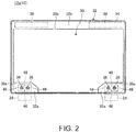
- FIG. 2 is a plan view schematically illustrating one example of the configuration of the rear face cover 12a of the chassis 12 and is the diagram that the rear face cover 12a which serves as the rear face of the lid body 16 has been viewed from the inner face side.
- FIG. 3 is a plan view enlargedly illustrating one example of a wide part 32a and its vicinity of the rear face cover 12a illustrated in FIG. 2 .
- the rear face cover 12a is formed by the member for chassis 10.
- the member for chassis 10 includes a laminated sheet 30 which has been formed so as to have a three-layer structure and so as to be light in weight and high in strength and a frame part 32 which has been formed by bonding a thermoplastic resin to an external-form end face 30a of the laminated sheet 30.
- the rear face cover 12a includes a wall part 34 which is formed by using the frame part 32 of the member for chassis 10 so configured and serves as a peripheral edge part and four side faces of the rear face cover 12a and a sheet-shaped part which supports the rear face of the display device 22 is formed by using the laminated sheet 30.
- the frame part 32 On the chassis 12 (the lid body 16), the frame part 32 is provided with one pair of the left and right wide parts 32a on one edge side (a lower edge in FIG. 2 ) of the rear face cover 12a.
- the hinges 24 are fixed to the left and right wide parts 32a respectively by using a plurality (two screws in FIG. 2 ) of fixing screws 36.
- the frame part 32 is provided with a belt-shaped part 32b which extends in a left-to-right direction on the other edge side (an upper edge in FIG. 2 ) of the rear face cover 12a.
- Antennas 38 for radio communications are arranged in the belt-shaped part 32b.
- FIG. 4 is a sectional diagram schematically illustrating one example of a sectional shape along the IV-IV line in FIG. 3 , that is, the sectional diagram in a thickness direction of a section which includes the laminated sheet 30 and the frame part 32 (the wide parts 32a) of the member for chassis 10.
- FIG. 5 is a sectional diagram illustrating one example of a state where the hinge 24 has been fixed to the member for chassis 10 illustrated in FIG. 4 by using the fixing screw 36.
- the member for chassis 10 includes the laminated sheet 30 that an intermediate layer 42 has been arranged between one pair of upper and lower fiber reinforced resin sheets 40 and 41 and the frame part 32 which has been bonded to the external-form end face 30a of the laminated sheet 30.
- Each of the fiber reinforced resin sheets 40 and 41 is a prepreg prepared by impregnating reinforced fibers with a thermosetting resin such as an epoxy resin and so forth and has a sheet thickness of, for example, about 0.3 mm.
- a carbon fiber reinforced resin (CFRP) that carbon fibers have been used as the reinforced fibers is used.
- CFRP carbon fiber reinforced resin
- fibers other than the carbon fibers may be used and various materials such as metal fibers such as stainless fibers and so forth and inorganic fibers such as glass fibers and so forth may be used.
- the intermediate layer 42 is arranged between one pair of the fiber reinforced resin sheets 40 and 41, serves as a soft spacer for isolating these hard fiber reinforced resin sheets 40 and 41 from each other and has a sheet thickness of, for example, about 0.6 mm. Owing to provision of the intermediate layer 42, a section modulus in a sheet thickness direction of the laminated sheet 30 is increased and the laminated sheet 30 has a light-weight and high-strength structure.
- the intermediate layer 42 is configured by, for example, a foamed layer which has been configured by a foamed sheet such as polypropylene and so forth, a fiber layer of the carbon fibers and so forth which have been assembled together with compressible gaps being contained therein and so forth.
- the frame part 32 is bonded to the laminated sheet 30 by injection-molding the thermoplastic resin to the external-form end face 30a of the laminated sheet 30 so configured.
- the thermoplastic resin which forms the frame part 32 for example, a polyethylene resin, a polypropylene resin and so forth may be used and also fiber reinforced resins (for example, GFRP) prepared by containing reinforced fibers such as glass fibers and so forth in these resins may be used.
- the anchoring effect is caused to occur by conducting injection molding so as to put the thermoplastic resin which forms the frame part 32 into the intermediate layer 42 which has been sandwiched between the fiber reinforced resin sheets 40 and 41 and thereby the high bond strength is ensured.
- each wide part 32a to which each hinge 24 has been screwed and fixed with the two fixing screws 36 is formed by extending the thermoplastic resin which has been bonded to the external-form end face 30a of the laminated sheet 30 to the surface (the surface of one fiber reinforced resin sheet 40) of the laminated sheet 30. That is, the wide part 32a is a part formed by providing the thermoplastic resin in the form of a thin sheet on the surface of the laminated sheet 30. Then, screwing and fixing of the hinge 24 is made possible by forming each nut 44 which serves as the female screw part into which the fixing screw 36 is to be screwed in the wide part 32a made of the thermoplastic resin which has been extended to the surface of the laminated sheet 30 by insert molding. That is, the nut 44 is arranged on the surface of the laminated sheet 30.
- Every two hole parts 46 are formed in the surface of the laminated sheet 30 which has been covered with the wide part 32a made of the thermoplastic resin which has been extended to the surface of the laminated sheet 30 at positions corresponding to each wide part 32a (also see FIG. 2 and FIG. 3 ).
- Each hole part 46 is formed so as to have a depth dimension that it extends from one fiber reinforced resin sheet 40 which serves as the surface of the laminated sheet 30 and reaches the intermediate layer 42.
- the thermoplastic resin which configures the wide part 32a enters each hole part 46 and forms each anchor part 48 in each hole part 46.
- the anchor part 48 makes the anchoring effect occur between the wide part 32a and the laminated sheet 30 in a direction (the in-plane direction) that the positions of both of the wide part 32a and the laminated sheet 30 deviate from each other in parallel thereby to make the high bond strength generate.
- the hole part 46 reaches the intermediate layer 42 and the injection molding is conducted such that the thermoplastic resin which forms the anchor part 48 enters the intermediate layer 42 which has been sandwiched between the fiber reinforced resin sheets 40 and 41.
- the anchor part 48 makes the anchoring effect occur between the wide part 32a and the laminated sheet 30 also in a direction that the wide part 32a and the laminated sheet 30 mutually superpose (the out-of-plane direction which is orthogonal to the in-plane direction) thereby to make the high bond strength generate.
- the hole part 46 is configured so as to have the depth dimension that the hole part 46 extends from one fiber reinforced resin sheet 40 and reaches the intermediate layer 42.
- the hole part 46 may have a depth dimension that the hole part 46 is formed in one fiber reinforced resin sheet 40 and does not reach the intermediate layer 42 or may have a depth dimension that the hole part 46 extends through the intermediate layer 42 down to the middle of the other fiber reinforced resin sheet 41 or further extends through the other fiber reinforced resin sheet 41.
- the nut 44 is insert-molded with the thermoplastic resin in a state of being arranged in abutment on the surface of the laminated sheet 30 whose one end face is covered with the wide part 32a. That is, the surrounding part other than the surface of the laminated sheet 30 and the other end face on the opening part side of the nut 44 is covered with the thermoplastic resin which has formed the wide part 32a. Thereby, the nut 44 is brought into a state where an outer circumferential surface thereof is surrounded by a cylindrical boss part 49 which stands upright from the surface of the laminated sheet 30 and is rigidly positioned and fixed with the thermoplastic resin which has formed the wide part 32a.
- the two anchor part 48 are provided at positions between the two mutually adjacent nuts 44, 44 adapted to fix one hinge 24 with the two fixing screws 36. Further, the two anchor parts 48 are provided so as to be arranged side by side in a direction (in a top-to-down direction in FIG. 2 and FIG. 3 ) which is orthogonal to a direction (in a left-to-right direction in FIG. 2 and FIG. 3 ) that the two mutually adjacent nuts 44, 44 are arranged side by side.
- one procedure of a manufacturing method for the member for chassis 10 configured in this way first, one pair of the planar-shape fiber reinforced resin sheets 40 and 41 is prepared, the planar-shape intermediate layer 42 is sandwiched between the one pair of the fiber reinforced resin sheets 40 and 41, the whole is pressed in a lamination direction and thereby the laminated sheet 30 is formed. Then, the laminated sheet 30 is set in a mold, the molten thermoplastic resin is charged into a cavity of the mold to injection-mold the thermoplastic resin so as to come into contact with the external-form end face 30a of the laminated sheet 30 and thereby the frame part 32 is formed.
- the hole part 46 used for provision of the anchor part 48 is formed in a predetermined place of the laminated sheet 30 that the frame part 32 has been bonded to the external-form end face 30a by machining, laser beam machining and so forth, the nut 44 is arranged on the surface of the laminated sheet 30 and is set in another mold. Then, the molten thermoplastic resin is charged into the cavity of the mold to injection-mold the thermoplastic resin so as to come into contact with the surface of the laminated sheet 30 (the fiber reinforced resin sheet 40) and thereby the wide part 32a in which the nut 44 is insert-molded and from which the boss part 49 has projected is formed.
- the member for chassis 10 which includes the frame part 32 formed by bonding the thermoplastic resin to the external-form end face 30a of the laminated sheet 30, the wide part 32a which has been formed by bonding the thermoplastic resin to the surface of the laminated sheet 30 and in which the nut 44 has been insert-molded, and the anchor part 48 formed by implanting the thermoplastic resin from the wide part 32a into the laminated sheet 30 is formed.
- the thermoplastic resin which forms the frame part 32 and the thermoplastic resin which forms the wide part 32a which holds the nut 44 and is provided with the anchor part 48 may be molded together in one mold.
- the hinge 24 when the hinge 24 is to be screwed to the member for chassis 10 configured in this way, as illustrated in FIG. 5 , the hinge 24 is placed on the wide part 32a and a screw part 36a of the fixing screw 36 is screwed into a screw part 44a of the nut 44.
- the rear face cover 12a that the hinges 24 have been screwed and fixed to the member for chassis 10 is formed, it is possible to construct the chassis 12 by superposing the front face cover 12b on the rear face cover 12a and coupling the covers 12a and 12b together.
- the thermoplastic resin is extended to the surface of the laminated sheet 30, the hole part 46 is formed in the surface of the laminated sheet 30 which has been covered with the extended thermoplastic resin and the member for chassis 10 includes the anchor part 48 formed by putting the thermoplastic resin into the hole part 46.
- the member for chassis 10 concerned includes the anchor parts 48 formed by putting the thermoplastic resin which has been extended from the external-form end face 30a of the laminated sheet 30 to the surface thereof into the hole part 46 in the laminated sheet 30.
- the thermoplastic resin which has been extended to the surface of the laminated sheet 30 integrally with the high-strength laminated sheet 30 with the high bond strength. Therefore, for example, it is possible to stably clamp and fix the other member to the member for chassis 10 by providing the female screw part and the nut 44 in the part of the thermoplastic resin which has been extended to the surface of the laminated sheet 30 or to stably adhere and fix the other member to the member for chassis 10 with an adhesive and so forth.
- the member for chassis 10 concerned owing to provision of the anchor part 48 in the vicinity of the nut 44 used for clamping and fixing the hinge 24, it is possible to secure the strength of the member for chassis 10 while avoiding an increase in thickness of the chassis on each part where the hinge 24 is formed.
- the nut 44 is superposed and arranged on the laminated sheet 30 which is higher in strength than the frame part 32 which has been formed using the thermoplastic resin.
- the nut 44 which has been insert-molded in and positioned and fixed to the boss part 49 which has been formed using the thermoplastic resin is provided as the female screw part in the part of the thermoplastic resin which has been extended to the surface of the laminated sheet 30. Accordingly, for example, in a case where the electronic apparatus 14 which is in a state where the lid body 16 has been closed and superposed on the apparatus main body 20 has been fallen to the ground and the floor surface, it is feared that the stress may be concentrated on the root of the boss part 49 and the boss part 49 may be broken under the influence of the shock concentrated on the hinge 24 and the boss part 49 and the nut 44 may fall off. In this point, since in the member for chassis 10 concerned, the thermoplastic resin which forms the boss part 49 is rigidly bonded to the laminated sheet 30 via the anchor part 48, it is possible to effectively prevent the boss part 49 and the nut 44 from falling off.
- the electronic apparatus 14 concerned has a configuration that as illustrated in FIG. 6 , the other end part (an open end part 50b) on the opposite side of one end part (a coupling end part 50a) of the chassis 12 which has been coupled with the apparatus main body 20 via the hinge 24 projects in a state where the position thereof deviates from the position of the other end part (an open end part 51b) on the opposite side of one end part (a coupling end 51a) on the hinge 24 side of the apparatus main body 20 by a distance L in a direction directing from one end parts toward the other end parts. Accordingly, as illustrated in FIG.
- the plurality of nuts 44 which are the female screw parts is arranged side by side in a direction (in the left-to-right direction in FIG. 2 and FIG. 3 ) along the coupling end parts 50a and 51a of the chassis 12 and the apparatus main body 20 which acts as the other chassis.
- the anchor part 48 is arranged at the position between the two mutually adjacent nuts 44 and 44 so as to fix one hinge 24 (see FIG. 2 and FIG. 3 ).
- the electronic apparatus 14 when the electronic apparatus 14 has been fallen in the state of directing the open end parts 50b and 51b downward as the lower ends as described above, it is possible to accept the loads generated on the two nuts 44 and 44 which have fixed one hinge 24 by the anchor part 48 which is arranged between the two nuts in a well-balanced state. Accordingly, the anti-shock property brought about by the anchor part 48 is more improved.
- the anchor parts 48 between the central nut 44 and the left end nut 44 and between the central nut 44 and the right end nut 44.
- one pair of the anchor parts 48 is arranged side by side in the direction (in the top-to-bottom direction in FIG. 2 and FIG. 3 ) directing from the coupling end parts 50a and 51a of the chassis 12 (the lid body 16) and the apparatus main body 20 toward the open end parts 50b and 51b on the opposite side.
- the electronic apparatus 14 has been fallen to the ground and so forth in the state of directing the open end parts 50b and 51b downward as the lower ends, it is possible to accept the loads generated on the two nuts 44 and 44 which have fixed one hinge 24 by the anchor parts 48 which have been arranged side by side in the orthogonal direction between the two nuts 44 and 44 in the more well-balanced state. Accordingly, the anti-shock property brought about by the anchor part 48 is more improved.
- the anchor part 48 is arranged in the state where the position thereof deviates from the position of the nut 44 which is the female screw part in the direction directing from the coupling end parts 50a and 51a toward the open end parts 50b and 51b on the opposite side of the chassis 12 and the apparatus main body 20 (see FIG. 3 ).
- the electronic apparatus 14 has been fallen in the state of directing the open end parts 50b and 51b downward as the lower ends, it is possible to accept the loads generated on the nuts 44 and 44 which have fixed the hinge 24 by the anchor part 48 the position of which deviates from the position of each nut 44 in the falling direction of the electronic apparatus 14 in the well-balanced state. Accordingly, the anti-shock property by the anchor part 48 is more improved.
- FIG. 7 is a plan view enlargedly illustrating the wide part 32a and its vicinity of the rear face cover 12a in a first altered example that the arrangement of the anchor parts 48 has been changed.
- one anchor part 48 may be provided for the adjacent nuts 44 and 44 as illustrated in FIG. 7 .
- the anchor part 48 may be arranged at a position located at the center between the two nuts 44 and 44.
- FIG. 8 is a plan view enlargedly illustrating the wide part 32a and its vicinity of the rear face cover 12a in a second altered example that the installation number of the nuts 44 has been changed.
- a configuration that one nut 44 has been used may be also made as illustrated in FIG. 8 .
- one pair of the anchor parts 48 may be used so as to sandwich the nut 44 between the anchor parts 48.
- a configuration that the anchor parts 48 are arranged side by side in the direction (the top-to-down direction in FIG. 8 ) directing from the coupling end part 50a toward the open end part 50b of the chassis 12 and the nut 44 is arranged between the anchor parts 48 may be made.
- the present invention is not limited to the above-mentioned embodiment and it is possible to freely change the configuration within a range not deviating from the gist of the present invention.
- the member for chassis 10 may be also used as the front face cover 12b and the apparatus main body 20.
- the member for chassis 10 it is possible to utilize the member for chassis 10 as the members of chassis of various electronic apparatuses such as the Laptop PC, the tablet PC, the smartphone and/or the portable phone and so forth.
- the female screw part (the nut 44) which configures the member for chassis 10 may be utilized for applications other than clamping of the hinge 24 and may be utilized, for example, as the female screw part used when clamping the front face cover 12b to the rear face cover 12a configured by the member for chassis 10.
- the laminated sheet 30 may have a laminated structure of five or more layers that each intermediate layer 42 has been sandwiched between the respective layers of, for example, the three or more fiber reinforced resin sheets 40 and 41.
- the female screw part may be also formed by performing screw forming directly on the thermoplastic resin which configures the wide part 32a.
Abstract
Description
- The present invention relates to a member for chassis which is utilizable as chassis of electronic apparatuses such as a Laptop PC, a tablet PC and so forth and an electronic apparatus using the member for chassis.
- It is requested for the chassis of various electronic apparatuses such as a notebook personal computer (the Laptop PC), a tablet type personal computer (the tablet PC), a smartphone, a portable phone and so forth to be light in weight, thin in thickness and high in strength. Accordingly, it is widely practiced to use a sheet-shaped laminated sheet that an intermediate layer which is made of a foamed material and so forth has been sandwiched between prepreg sheets (fiber reinforced resin sheets) prepared by impregnating reinforced fibers such as carbon fibers and so forth with a thermosetting resin such as an epoxy resin and so forth in the chassis of the electronic apparatus.
- When such a laminated sheet is to be used in the chassis of the Laptop PC and so forth, it is requested to perform machining of a desirable shape such as a wall part and so forth at least on a peripheral edge part of the laminated sheet. However, since the laminated sheet is configured by using a hard fiber reinforced resin sheet, the laminated sheet is low in degree of freedom of shape machining such as bending and so forth.
- Accordingly, the applicant of the present application proposes a configuration that a thermoplastic resin has been injection-molded and bonded to an external-form end face of the laminated sheet (see Patent Document 1). Since in this configuration, it is possible to ensure the degree of freedom of shape machining by a thermoplastic resin part which has been bonded to the laminated sheet, it is possible to widely utilize the laminated sheet as the members for chassis of various shapes and specifications.
- [Patent Document 1] Japanese Patent Application Laid-Open No.
2013-232052 - Incidentally, when configuring the chassis by coupling and fixing the member for chassis which has been described in the above-mentioned
Patent Document 1 to the other member for chassis, for example, it is practiced to form a nut which configures a female screw part by insert-molding in the thermoplastic resin part which has been bonded to the laminated sheet. - However, in such a configuration, since the nut is arranged in the thermoplastic resin part which has been bonded to a part which is located outside of the external-form end face of the laminated sheet, in a case where a shock and external force have been applied to the chassis, these shock and external force are transmitted from a screw which clamps together the two members for chassis directly to the thermoplastic resin part via the nut. Consequently, there is a tendency that the load on the thermoplastic resin part which is inferior, in strength, to a laminated sheet part having a high strength or a bonded interface between the thermoplastic resin part and the laminated sheet is increased and therefore a member for chassis which makes it possible to more increase the strength of the chassis is requested. In particular, in a case where the nut which has been formed by such insert-molding has been utilized for fixing a hinge which couples together two chassis of the Laptop PC, it is feared that most of the load of the Laptop PC which has fallen would be applied to the nut and the thermoplastic resin which holds the nut would be broken.
- The present invention has been made in consideration of the above-mentioned disadvantages of the related art and aims to provide a member for chassis which makes it possible to obtain a high strength and an electronic apparatus using the member for chassis.
- The member for chassis according to the present invention is a member for chassis that a thermoplastic resin has been bonded to at least a part of an external-form end face of a laminated sheet that an intermediate layer has been arranged between one pair of fiber reinforced resin sheets, in which the thermoplastic resin is extended to a surface of the laminated sheet, and a hole part is provided in the surface of the laminated sheet which has been covered with the extended thermoplastic resin and the member for chassis includes an anchor part formed by putting the thermoplastic resin into the hole part.
- It is possible to configure the thermoplastic resin which has been extended to the surface of the laminated sheet integrally with the high-strength laminated sheet with high bond strength owing to an anchoring effect by the anchor part, by configuring the member for chassis in this way. Accordingly, for example, in a case where the member for cassis has been structured such that that the other member or the like has been fixed to the thermoplastic resin which has been extended to the surface of the laminated sheet by adhesive bonding and screw clamping, even when the external force and the shock have been imparted to this part, it is possible to accept the external force and the shock by the high-strength laminated sheet via the anchor part. Consequently, breakage of the thermoplastic resin which has been extended to the surface of the laminated sheet and/or delamination of this thermoplastic resin from the surface of the laminated sheet is/are suppressed and it is possible to obtain the chassis which is high in strength and high in anti-shock property.
- The member for chassis may also have such a configuration that a female screw part is provided in a part of the thermoplastic resin which has been extended to the surface of the laminated sheet. Then, for example, even when the load has been concentrated on the female screw part when the chassis of the electronic apparatus and so forth using the member for chassis concerned has been fallen to the ground and a floor surface, it is possible to prevent the female screw part from being broken because the thermoplastic resin is rigidly bonded to the laminated sheet by the anchor part.
- The female screw part may be configured by a nut which has been positioned and fixed by a boss part which has been formed by using the thermoplastic resin. Also in this case, it is possible to accept the shock and the external force imparted to the nut owing to the anchoring effect of the anchor part and it is possible to ensure the high strength.
- The member for chassis may also have such a configuration that a plurality of the female screw parts is arranged side by side and the anchor part is arranged at a position between the two mutually adjacent female screw parts. Thereby, for example, when the load which works in a direction orthogonal to a direction that the female screw parts are arranged side by side has been applied to each female screw part, it is possible to accept this load by the anchor part which is interposed between the female screw parts in a well-balanced state. Accordingly, the anti-shock property by the anchor part is more improved.
- The member for chassis may also have such a configuration that a plurality of the anchor parts is arranged side by side in a direction which is orthogonal to a direction that the two mutually adjacent female screw parts are arranged side by side. Then, for example, when the load which works in a direction orthogonal to the direction that the two mutually adjacent female screw parts are arranged side by side has been applied to each female screw part, it is possible to accept the load by the anchor part which is interposed between the mutually adjacent female screw parts in the more well-balanced state and rigidly.
- The member for chassis may also have such a configuration that the hole part extends from the surface of the laminated sheet and reaches the intermediate layer and the anchor part has been put into the intermediate layer. Then, the anchor part generates a high anchoring effect also in an out-of-plane direction which is orthogonal to an in-plane direction in addition to the anchoring effect which acts in the in-plane direction between the thermoplastic resin and the laminated sheet which is located under the thermoplastic resin and it is possible to obtain the high bond strength.
- In addition, the electronic apparatus according to the present invention is an electronic apparatus which includes a chassis which uses a member for chassis that a thermoplastic resin has been bonded to at least a part of an external-form end face of a laminated sheet that an intermediate layer has been arranged between one pair of fiber reinforced resin sheets, in which in the member for chassis, the thermoplastic resin is extended to a surface of the laminated sheet and a hole part is provided in the surface of the laminated sheet which has been covered with the extended thermoplastic resin and the member for chassis includes an anchor part formed by putting the thermoplastic resin into the hole part.
- In this case, the electronic apparatus may also have such a configuration that the electronic apparatus further includes the other chassis which has been coupled with the chassis to be openable and closable via a hinge, in which on the member for chassis, a female screw part is provided in a part of the thermoplastic resin which has been extended to the surface of the laminated sheet and the hinge is screwed and fixed to the female screw part. Then, even in a case where a shock which has been generated, for example, when the electronic apparatus concerned has been fallen has been applied to the female screw part via the hinge, breakage of the female screw part and the thermoplastic resin around the female screw part is avoided by a high bonding action by the anchor part.
- The electronic apparatus may also have such a configuration that a plurality of the female screw parts is arranged side by side in a direction along one end parts of the chassis and the other chassis which have been coupled with each other by the hinge and the anchor part has been provided at a position between the two mutually adjacent female screw parts. Thereby, for example, in a case where the electronic apparatus has been fallen in a state of directing the other end part on the opposite side of the hinge side downward as a lower end, it is possible to accept the shock which has been applied to the female parts which configure the hinge by the anchor part in the well-balanced state.
- The electronic apparatus may also have such a configuration that a plurality of the anchor parts is arranged side by side in a direction directing from one end parts of the chassis and the other chassis which have been coupled with each other by the hinge to the opposite-side other end parts of the chassis and the other chassis. Then, the anti-shock property of the electronic apparatus concerned is more improved.
- The electronic apparatus may also have such a configuration that the anchor part is provided in a state where the position thereof deviates from the position of the female screw part in a direction directing from one end parts of the chassis and the other chassis which have been coupled together by the hinge to the opposite-side other end parts of the chassis and the other chassis. Then, it is possible to accept the shock which has been generated when the electronic apparatus has been fallen in the state of directing the other end part on the opposite side of the hinge side downward as the lower end by the anchor part which has been provided in the state where the position thereof deviates from the position of the female screw part in a falling direction of the electronic apparatus in the more well-balanced state.
- The electronic apparatus may also have such a configuration that on the chassis, the other end part on the opposite side of the one end part at which the chassis has been coupled with the other chassis by the hinge projects in a state where the position thereof deviates from the position of the other end part of the other chassis in a direction directing from the one end parts to the other end parts of the chassis and the other chassis. That is, in a case where the electronic apparatus so configured has been fallen in a state of directing the other end part downward as the lower end, the most projected other end part of the chassis comes into abutment on the ground and so forth under the influence of the shock earlier than the other end part of the other chassis. Then, the load of this chassis and the load of the other chassis which has been coupled thereto via the hinge are fully applied to the hinge and the loads act to the female screw part. However, in the electronic apparatus concerned, the thermoplastic resins in which this female screw part has been provided is implanted into the laminated sheet as the anchor part. Therefore, it is possible to accept the load which has acted from the other chassis to the female screw part via the hinge by the high-strength laminated sheet via the anchor part and the female screw part and its surrounding part are effectively prevented from being broken.
- According to one embodiment of the present invention, it is possible to configure the thermoplastic resin which has been extended to the surface of the laminated sheet integrally with the high-strength laminated sheet with the high bond strength owing to the anchoring effect by the anchor part and it is possible to obtain the high strength.
-
-
FIG. 1 is a perspective view illustrating one example of an electronic apparatus which includes a chassis using a member for chassis according to one embodiment of the present invention. -
FIG. 2 is a plan view schematically illustrating one example of a configuration of a rear face cover of the chassis. -
FIG. 3 is a plan view enlargedly illustrating one example of a wide part and its vicinity of the rear face cover illustrated inFIG. 2 . -
FIG. 4 is a sectional diagram schematically illustrating one example of a sectional shape of the member for chassis along the IV-IV line inFIG. 3 . -
FIG. 5 is a sectional diagram illustrating one example of a state where a hinge has been fixed to the member for chassis illustrated inFIG. 4 by using a fixing screw. -
FIG. 6 is a side view schematically illustrating one example of a structure of the electronic apparatus illustrated inFIG. 1 , in a state where a lid body thereof has been closed. -
FIG. 7 is a plan view enlargedly illustrating one example of the wide part and its vicinity of the rear face cover in a first altered example that the arrangement of the anchor part has been changed. -
FIG. 8 is a plan view enlargedly illustrating one example of the wide part and its vicinity of the rear face cover in a second altered example that the installation number of nuts has been changed. - In the following, a member for chassis according to the present invention will be described in detail by giving a preferred embodiment which exemplifies an electronic apparatus using this member while referring to the appended drawings.
-
FIG. 1 is a perspective view illustrating one example of anelectronic apparatus 14 which includes achassis 12 using a member forchassis 10 according to one embodiment of the present invention. In the present embodiment, a configuration that thechassis 12 which has used the member forchassis 10 has been used as alid body 16 of theelectronic apparatus 14 which is a Laptop PC is exemplified. - As illustrated in
FIG. 1 , theelectronic apparatus 14 includes an apparatusmain body 20 having akeyboard device 18 and the rectangular sheet-shaped lid body 16 having adisplay device 22 which is configured by a liquid crystal display and so forth. Theelectronic apparatus 14 is a clamshell type apparatus that thelid body 16 has been coupled to the apparatusmain body 20 to be openable and closable by left andright hinges 24. - The apparatus
main body 20 is a flat box-shaped chassis and houses various electronic components such as a substrate, an arithmetic processing device, a hard disk device, a memory and so forth which are not illustrated inFIG. 1 . Thekeyboard device 18 is arranged on an upper surface of the apparatusmain body 20. - The
lid body 16 includes thechassis 12 formed by superposing and coupling together arear face cover 12a and afront face cover 12b and is electrically connected with the apparatusmain body 20 by a not illustrated cable which has passed through thehinges 24. Therear face cover 12a is a cover member which covers side faces and a rear face of thelid body 16 and is configured by the member forchassis 10 according to the present embodiment. Thelid body 16 is coupled with the apparatusmain body 20 via thehinges 24 which have been screwed and fixed to therear face cover 12a (also seeFIG. 2 ). Thefront face cover 12b is a resinous cover member which covers the front face of thelid body 16 and a hole part through which thedisplay device 22 which is configured by, for example, the liquid crystal display is exposed is formed in most part of thefront face cover 12b. - Next, configurations of the
rear face cover 12a of thechassis 12 which configures thelid body 16 and the member forchassis 10 which forms thisrear face cover 12a will be specifically described. - First, the overall configuration of the
rear face cover 12a will be described.FIG. 2 is a plan view schematically illustrating one example of the configuration of therear face cover 12a of thechassis 12 and is the diagram that therear face cover 12a which serves as the rear face of thelid body 16 has been viewed from the inner face side.FIG. 3 is a plan view enlargedly illustrating one example of awide part 32a and its vicinity of therear face cover 12a illustrated inFIG. 2 . - As described above, the
rear face cover 12a is formed by the member forchassis 10. As illustrated inFIG. 2 andFIG. 3 , the member forchassis 10 includes alaminated sheet 30 which has been formed so as to have a three-layer structure and so as to be light in weight and high in strength and aframe part 32 which has been formed by bonding a thermoplastic resin to an external-form end face 30a of thelaminated sheet 30. Therear face cover 12a includes awall part 34 which is formed by using theframe part 32 of the member forchassis 10 so configured and serves as a peripheral edge part and four side faces of therear face cover 12a and a sheet-shaped part which supports the rear face of thedisplay device 22 is formed by using thelaminated sheet 30. - On the chassis 12 (the lid body 16), the
frame part 32 is provided with one pair of the left and rightwide parts 32a on one edge side (a lower edge inFIG. 2 ) of therear face cover 12a. The hinges 24 are fixed to the left and rightwide parts 32a respectively by using a plurality (two screws inFIG. 2 ) of fixing screws 36. Theframe part 32 is provided with a belt-shapedpart 32b which extends in a left-to-right direction on the other edge side (an upper edge inFIG. 2 ) of therear face cover 12a.Antennas 38 for radio communications are arranged in the belt-shapedpart 32b. - Next, a specific configuration of the member for
chassis 10 which configures therear face cover 12a will be described.FIG. 4 is a sectional diagram schematically illustrating one example of a sectional shape along the IV-IV line inFIG. 3 , that is, the sectional diagram in a thickness direction of a section which includes thelaminated sheet 30 and the frame part 32 (thewide parts 32a) of the member forchassis 10. In addition,FIG. 5 is a sectional diagram illustrating one example of a state where thehinge 24 has been fixed to the member forchassis 10 illustrated inFIG. 4 by using the fixingscrew 36. - As illustrated in
FIG. 4 , the member forchassis 10 includes thelaminated sheet 30 that anintermediate layer 42 has been arranged between one pair of upper and lower fiber reinforcedresin sheets frame part 32 which has been bonded to the external-form end face 30a of thelaminated sheet 30. - Each of the fiber reinforced
resin sheets - The
intermediate layer 42 is arranged between one pair of the fiber reinforcedresin sheets resin sheets intermediate layer 42, a section modulus in a sheet thickness direction of thelaminated sheet 30 is increased and thelaminated sheet 30 has a light-weight and high-strength structure. Theintermediate layer 42 is configured by, for example, a foamed layer which has been configured by a foamed sheet such as polypropylene and so forth, a fiber layer of the carbon fibers and so forth which have been assembled together with compressible gaps being contained therein and so forth. - The
frame part 32 is bonded to thelaminated sheet 30 by injection-molding the thermoplastic resin to the external-form end face 30a of thelaminated sheet 30 so configured. As the thermoplastic resin which forms theframe part 32, for example, a polyethylene resin, a polypropylene resin and so forth may be used and also fiber reinforced resins (for example, GFRP) prepared by containing reinforced fibers such as glass fibers and so forth in these resins may be used. In the case of the present embodiment, the anchoring effect is caused to occur by conducting injection molding so as to put the thermoplastic resin which forms theframe part 32 into theintermediate layer 42 which has been sandwiched between the fiber reinforcedresin sheets - It is possible to perform machining of a desirable shape such as the
wall part 34 and so forth on the peripheral edge part of thelaminated sheet 30 which is low in degree of freedom in machining such as bending, cutting and so forth by bonding theframe part 32 so formed to thelaminated sheet 30. In addition, it is also possible to improve the degree of design freedom in installation of theantennas 38 in theframe part 32 which is made of a nonconductive material at positions distant from the fiber reinforcedresin sheets FIG. 2 ). Although a configuration that theframe part 32 has been provided on the whole circumference of the external-form end face 30a of thelaminated sheet 30 is illustrated inFIG. 2 by way of example, theframe part 32 may be also bonded to only a part of the external-form end face 30a. - As illustrated in
FIG. 3 to FIG. 5 , eachwide part 32a to which each hinge 24 has been screwed and fixed with the two fixingscrews 36 is formed by extending the thermoplastic resin which has been bonded to the external-form end face 30a of thelaminated sheet 30 to the surface (the surface of one fiber reinforced resin sheet 40) of thelaminated sheet 30. That is, thewide part 32a is a part formed by providing the thermoplastic resin in the form of a thin sheet on the surface of thelaminated sheet 30. Then, screwing and fixing of thehinge 24 is made possible by forming eachnut 44 which serves as the female screw part into which the fixingscrew 36 is to be screwed in thewide part 32a made of the thermoplastic resin which has been extended to the surface of thelaminated sheet 30 by insert molding. That is, thenut 44 is arranged on the surface of thelaminated sheet 30. - Every two
hole parts 46 are formed in the surface of thelaminated sheet 30 which has been covered with thewide part 32a made of the thermoplastic resin which has been extended to the surface of thelaminated sheet 30 at positions corresponding to eachwide part 32a (also seeFIG. 2 andFIG. 3 ). Eachhole part 46 is formed so as to have a depth dimension that it extends from one fiber reinforcedresin sheet 40 which serves as the surface of thelaminated sheet 30 and reaches theintermediate layer 42. The thermoplastic resin which configures thewide part 32a enters eachhole part 46 and forms eachanchor part 48 in eachhole part 46. Theanchor part 48 makes the anchoring effect occur between thewide part 32a and thelaminated sheet 30 in a direction (the in-plane direction) that the positions of both of thewide part 32a and thelaminated sheet 30 deviate from each other in parallel thereby to make the high bond strength generate. - Moreover, in the present embodiment, the
hole part 46 reaches theintermediate layer 42 and the injection molding is conduced such that the thermoplastic resin which forms theanchor part 48 enters theintermediate layer 42 which has been sandwiched between the fiber reinforcedresin sheets anchor part 48 makes the anchoring effect occur between thewide part 32a and thelaminated sheet 30 also in a direction that thewide part 32a and thelaminated sheet 30 mutually superpose (the out-of-plane direction which is orthogonal to the in-plane direction) thereby to make the high bond strength generate. - Incidentally, in the present embodiment, the
hole part 46 is configured so as to have the depth dimension that thehole part 46 extends from one fiber reinforcedresin sheet 40 and reaches theintermediate layer 42. However, thehole part 46 may have a depth dimension that thehole part 46 is formed in one fiber reinforcedresin sheet 40 and does not reach theintermediate layer 42 or may have a depth dimension that thehole part 46 extends through theintermediate layer 42 down to the middle of the other fiber reinforcedresin sheet 41 or further extends through the other fiber reinforcedresin sheet 41. - The
nut 44 is insert-molded with the thermoplastic resin in a state of being arranged in abutment on the surface of thelaminated sheet 30 whose one end face is covered with thewide part 32a. That is, the surrounding part other than the surface of thelaminated sheet 30 and the other end face on the opening part side of thenut 44 is covered with the thermoplastic resin which has formed thewide part 32a. Thereby, thenut 44 is brought into a state where an outer circumferential surface thereof is surrounded by acylindrical boss part 49 which stands upright from the surface of thelaminated sheet 30 and is rigidly positioned and fixed with the thermoplastic resin which has formed thewide part 32a. - As illustrated in
FIG. 2 andFIG. 3 , the twoanchor part 48 are provided at positions between the two mutuallyadjacent nuts hinge 24 with the two fixing screws 36. Further, the twoanchor parts 48 are provided so as to be arranged side by side in a direction (in a top-to-down direction inFIG. 2 andFIG. 3 ) which is orthogonal to a direction (in a left-to-right direction inFIG. 2 andFIG. 3 ) that the two mutuallyadjacent nuts - As one procedure of a manufacturing method for the member for
chassis 10 configured in this way, first, one pair of the planar-shape fiber reinforcedresin sheets intermediate layer 42 is sandwiched between the one pair of the fiber reinforcedresin sheets laminated sheet 30 is formed. Then, thelaminated sheet 30 is set in a mold, the molten thermoplastic resin is charged into a cavity of the mold to injection-mold the thermoplastic resin so as to come into contact with the external-form end face 30a of thelaminated sheet 30 and thereby theframe part 32 is formed. - Next, the
hole part 46 used for provision of theanchor part 48 is formed in a predetermined place of thelaminated sheet 30 that theframe part 32 has been bonded to the external-form end face 30a by machining, laser beam machining and so forth, thenut 44 is arranged on the surface of thelaminated sheet 30 and is set in another mold. Then, the molten thermoplastic resin is charged into the cavity of the mold to injection-mold the thermoplastic resin so as to come into contact with the surface of the laminated sheet 30 (the fiber reinforced resin sheet 40) and thereby thewide part 32a in which thenut 44 is insert-molded and from which theboss part 49 has projected is formed. - Consequently, as illustrated in
FIG. 4 , the member forchassis 10 which includes theframe part 32 formed by bonding the thermoplastic resin to the external-form end face 30a of thelaminated sheet 30, thewide part 32a which has been formed by bonding the thermoplastic resin to the surface of thelaminated sheet 30 and in which thenut 44 has been insert-molded, and theanchor part 48 formed by implanting the thermoplastic resin from thewide part 32a into thelaminated sheet 30 is formed. Incidentally, the thermoplastic resin which forms theframe part 32 and the thermoplastic resin which forms thewide part 32a which holds thenut 44 and is provided with theanchor part 48 may be molded together in one mold. - Incidentally, when the
hinge 24 is to be screwed to the member forchassis 10 configured in this way, as illustrated inFIG. 5 , thehinge 24 is placed on thewide part 32a and ascrew part 36a of the fixingscrew 36 is screwed into ascrew part 44a of thenut 44. Thereby, since therear face cover 12a that thehinges 24 have been screwed and fixed to the member forchassis 10 is formed, it is possible to construct thechassis 12 by superposing thefront face cover 12b on therear face cover 12a and coupling thecovers - As described above, in the member for
chassis 10 according to the present embodiment, in the configuration that theframe part 32 which is made of the thermoplastic resin has been bonded to at least a part of the external-form end face 30a of thelaminated sheet 30 that theintermediate layer 42 has been arranged between the one pair of fiber reinforcedresin sheets laminated sheet 30, thehole part 46 is formed in the surface of thelaminated sheet 30 which has been covered with the extended thermoplastic resin and the member forchassis 10 includes theanchor part 48 formed by putting the thermoplastic resin into thehole part 46. - As described above, the member for
chassis 10 concerned includes theanchor parts 48 formed by putting the thermoplastic resin which has been extended from the external-form end face 30a of thelaminated sheet 30 to the surface thereof into thehole part 46 in thelaminated sheet 30. Thereby, it is possible to configure the thermoplastic resin which has been extended to the surface of thelaminated sheet 30 integrally with the high-strengthlaminated sheet 30 with the high bond strength. Therefore, for example, it is possible to stably clamp and fix the other member to the member forchassis 10 by providing the female screw part and thenut 44 in the part of the thermoplastic resin which has been extended to the surface of thelaminated sheet 30 or to stably adhere and fix the other member to the member forchassis 10 with an adhesive and so forth. Accordingly, even when the external force and the shock have been applied to the other member which has been fixed to the part of the thermoplastic resin and the member for chassis concerned 10, it is possible to accept the external force and the shock by the high-strengthlaminated sheet 30 via theanchor part 48. Consequently, breakage of the thermoplastic resin which has been extended to the surface of thelaminated sheet 30 and/or delamination of the thermoplastic resin from the surface of thelaminated sheet 30 are/is suppressed and it is possible to obtain thechassis 12 which is high in strength and high in anti-shock property. In particular, in the member forchassis 10 concerned, owing to provision of theanchor part 48 in the vicinity of thenut 44 used for clamping and fixing thehinge 24, it is possible to secure the strength of the member forchassis 10 while avoiding an increase in thickness of the chassis on each part where thehinge 24 is formed. - In addition, in the member for
chassis 10 concerned, thenut 44 is superposed and arranged on thelaminated sheet 30 which is higher in strength than theframe part 32 which has been formed using the thermoplastic resin. Thereby, for example, in a configuration that thehinge 24 has been clamped and fixed to the member forchassis 10 by screwing the fixingscrew 36 into thenut 44, even when the external force which works in a bending direction has been added to therear face cover 12a which configures thechassis 12, thenut 44 and theboss part 49 which holds thenut 44 are arranged on thelaminated sheet 30 and therefore it is possible to accept this external force by thelaminated sheet 30. In addition, thelaminated sheet 30 and the thermoplastic resin which forms theboss part 49 are bonded together via theanchor part 48. Consequently, it is possible to avoid application of heavy loads onto theframe part 32 which has been formed using the thermoplastic resin which is inferior to thelaminated sheet 30 in strength and onto a bonded interface between theframe part 32 and the external-form end face 30a of thelaminated sheet 30. - In the member for
chassis 10 concerned, thenut 44 which has been insert-molded in and positioned and fixed to theboss part 49 which has been formed using the thermoplastic resin is provided as the female screw part in the part of the thermoplastic resin which has been extended to the surface of thelaminated sheet 30. Accordingly, for example, in a case where theelectronic apparatus 14 which is in a state where thelid body 16 has been closed and superposed on the apparatusmain body 20 has been fallen to the ground and the floor surface, it is feared that the stress may be concentrated on the root of theboss part 49 and theboss part 49 may be broken under the influence of the shock concentrated on thehinge 24 and theboss part 49 and thenut 44 may fall off. In this point, since in the member forchassis 10 concerned, the thermoplastic resin which forms theboss part 49 is rigidly bonded to thelaminated sheet 30 via theanchor part 48, it is possible to effectively prevent theboss part 49 and thenut 44 from falling off. - In particular, the
electronic apparatus 14 concerned has a configuration that as illustrated inFIG. 6 , the other end part (anopen end part 50b) on the opposite side of one end part (acoupling end part 50a) of thechassis 12 which has been coupled with the apparatusmain body 20 via thehinge 24 projects in a state where the position thereof deviates from the position of the other end part (anopen end part 51b) on the opposite side of one end part (acoupling end 51a) on thehinge 24 side of the apparatusmain body 20 by a distance L in a direction directing from one end parts toward the other end parts. Accordingly, as illustrated inFIG. 6 , in a case where theelectronic apparatus 14 which is in the state where thelid body 16 has been closed and superposed on the apparatusmain body 20 has been fallen to the ground and the floor surface in a state of directing theopen end parts open end part 50b of thelid body 16 comes into abutment on the ground and so forth under the influence of the shock. Then, the load of the apparatusmain body 20 which has been coupled with thelid body 16 via thehinge 24 is fully applied to thehinge 24 and the load acts on thenut 44 and theboss part 49. However, in theelectronic apparatus 14 concerned, the thermoplastic resin which forms theboss parts 49 is implanted into thelaminated sheet 30 as theanchor part 48. Therefore, it is possible to accept the load which has been applied from the apparatusmain body 20 and has acted on thenut 44 and theboss part 49 via thehinge 24 by the high-strengthlaminated sheet 30 via theanchor part 48 and theboss part 49 and thenut 44 are effectively prevented from being broken and falling off. In particular, in the general Laptop PC, since there are many cases where the apparatusmain body 20 is configured by an article which is heavier than thelid body 16, the anchoring effect by theanchor parts 48 becomes highly effective. - In the
electronic apparatus 14 concerned, the plurality ofnuts 44 which are the female screw parts is arranged side by side in a direction (in the left-to-right direction inFIG. 2 andFIG. 3 ) along thecoupling end parts chassis 12 and the apparatusmain body 20 which acts as the other chassis. Then, theanchor part 48 is arranged at the position between the two mutuallyadjacent nuts FIG. 2 andFIG. 3 ). Thereby, for example, when theelectronic apparatus 14 has been fallen in the state of directing theopen end parts nuts hinge 24 by theanchor part 48 which is arranged between the two nuts in a well-balanced state. Accordingly, the anti-shock property brought about by theanchor part 48 is more improved. For example, in a case where the threenuts 44 have been arranged adjacently to one another in the left-to-right direction, it is preferable to arrange theanchor parts 48 between thecentral nut 44 and theleft end nut 44 and between thecentral nut 44 and theright end nut 44. - In the
electronic apparatus 14 concerned, one pair of theanchor parts 48 is arranged side by side in the direction (in the top-to-bottom direction inFIG. 2 andFIG. 3 ) directing from thecoupling end parts main body 20 toward theopen end parts electronic apparatus 14 has been fallen to the ground and so forth in the state of directing theopen end parts nuts hinge 24 by theanchor parts 48 which have been arranged side by side in the orthogonal direction between the twonuts anchor part 48 is more improved. - In the
electronic apparatus 14 concerned, theanchor part 48 is arranged in the state where the position thereof deviates from the position of thenut 44 which is the female screw part in the direction directing from thecoupling end parts open end parts chassis 12 and the apparatus main body 20 (seeFIG. 3 ). Thereby, for example, when theelectronic apparatus 14 has been fallen in the state of directing theopen end parts hinge 24 by theanchor part 48 the position of which deviates from the position of eachnut 44 in the falling direction of theelectronic apparatus 14 in the well-balanced state. Accordingly, the anti-shock property by theanchor part 48 is more improved. - As a matter of course, it is possible to appropriately change the number of the nuts 44 to be installed as the female screw parts and the arrangement of the
anchor parts 48. For example,FIG. 7 is a plan view enlargedly illustrating thewide part 32a and its vicinity of therear face cover 12a in a first altered example that the arrangement of theanchor parts 48 has been changed. Although, in the above-mentioned embodiment, the configuration that the twoanchor parts 48 have been arranged side by side in the direction which is orthogonal to the direction that the nuts 44 and 44 have been arranged side by side at the positions between theadjacent nuts anchor part 48 may be provided for theadjacent nuts FIG. 7 . In a case where only oneanchor part 48 is to be provided for the twonuts anchor part 48 may be arranged at a position located at the center between the twonuts - In addition, for example,
FIG. 8 is a plan view enlargedly illustrating thewide part 32a and its vicinity of therear face cover 12a in a second altered example that the installation number of the nuts 44 has been changed. In the above-mentioned example, the configuration that the twonuts 44 are used for onehinge 24 has been exemplified, a configuration that onenut 44 has been used may be also made as illustrated inFIG. 8 . In the case of this configuration, for example, one pair of theanchor parts 48 may be used so as to sandwich thenut 44 between theanchor parts 48. In particular, in the case of theelectronic apparatus 14, a configuration that theanchor parts 48 are arranged side by side in the direction (the top-to-down direction inFIG. 8 ) directing from thecoupling end part 50a toward theopen end part 50b of thechassis 12 and thenut 44 is arranged between theanchor parts 48 may be made. - Incidentally, it goes without saying that the present invention is not limited to the above-mentioned embodiment and it is possible to freely change the configuration within a range not deviating from the gist of the present invention.
- For example, although in the above-mentioned embodiment, the configuration that the member for
chassis 10 has been used as therear face cover 12a of thechassis 12 of thelid body 16 which configures theelectronic apparatus 14 has been exemplified, the member forchassis 10 may be also used as thefront face cover 12b and the apparatusmain body 20. In addition, it is possible to utilize the member forchassis 10 as the members of chassis of various electronic apparatuses such as the Laptop PC, the tablet PC, the smartphone and/or the portable phone and so forth. In addition, the female screw part (the nut 44) which configures the member forchassis 10 may be utilized for applications other than clamping of thehinge 24 and may be utilized, for example, as the female screw part used when clamping thefront face cover 12b to therear face cover 12a configured by the member forchassis 10. - Although in the above-mentioned embodiment, the member for
chassis 10 using thelaminated sheet 30 of the three-layer structure has been exemplified, thelaminated sheet 30 may have a laminated structure of five or more layers that eachintermediate layer 42 has been sandwiched between the respective layers of, for example, the three or more fiber reinforcedresin sheets - Although in the above-mentioned embodiment, the configuration that the
nut 44 has been insert-molded by using the thermoplastic resin which configures thewide part 32a has been exemplified, the female screw part may be also formed by performing screw forming directly on the thermoplastic resin which configures thewide part 32a. -
- 10
- member for chassis
- 12
- chassis
- 12a
- rear face cover
- 12b
- front face cover
- 14
- electronic apparatus
- 16
- lid body
- 18
- keyboard device
- 20
- apparatus main body
- 22
- display device
- 24
- hinge
- 30
- laminated sheet
- 30a
- external-form end face
- 32
- frame part
- 32a
- wide part
- 36
- fixing screw
- 40, 41
- fiber reinforced resin sheet
- 42
- intermediate layer
- 44
- nut
- 46
- hole part
- 48
- anchor part
- 49
- boss part
- 50a, 51a
- coupling end part
- 50b, 51b
- open end part
Claims (12)
- A member for chassis that a thermoplastic resin has been bonded to at least a part of an external-form end face of a laminated sheet that an intermediate layer has been arranged between one pair of fiber reinforced resin sheets, wherein
the thermoplastic resin is extended to a surface of the laminated sheet, and
a hole part is provided in the surface of the laminated sheet which has been covered with the extended thermoplastic resin and the member for chassis includes an anchor part formed by putting the thermoplastic resin into the hole part. - The member for chassis according to claim 1, wherein
a female screw part is provided in a part of the thermoplastic resin which has been extended to the surface of the laminated sheet. - The member for chassis according to claim 2, wherein
the female screw part is a nut which has been positioned and fixed by a boss part which has been formed by using the thermoplastic resin. - The member for chassis according to claim 2 or 3, wherein
a plurality of the female screw parts is arranged side by side, and
the anchor part is arranged at a position between the two mutually adjacent female screw parts. - The member for chassis according to claim 4, wherein
a plurality of the anchor parts is arranged side by side in a direction which is orthogonal to a direction that the two mutually adjacent female screw parts are arranged side by side. - The member for chassis according to any one of claims 1 to 5, wherein
the hole part extends from the surface of the laminated sheet and reaches the intermediate layer, and
the anchor part is put into the intermediate layer. - An electronic apparatus comprising:a chassis which uses a member for chassis that a thermoplastic resin has been bonded to at least a part of an external-form end face of a laminated sheet that an intermediate layer has been arranged between one pair of fiber reinforced resin sheets, whereinin the member for chassis, the thermoplastic resin is extended to a surface of the laminated sheet, anda hole part is provided in the surface of the laminated sheet which has been covered with the extended thermoplastic resin and the member for chassis includes an anchor part formed by putting the thermoplastic resin into the hole part.
- The electronic apparatus according to claim 7, further comprising:the other chassis which has been coupled with the chassis to be openable and closable via a hinge, whereinon the member for chassis, a female screw part is provided in a part of the thermoplastic resin which has been extended to the surface of the laminated sheet and the hinge is screwed and fixed to the female screw part.
- The electronic apparatus according to claim 8, wherein
a plurality of the female screw parts is arranged side by side in a direction along one end parts of the chassis and the other chassis which have been coupled with each other by the hinge, and
the anchor part is provided at a position between the two mutually adjacent female screw parts. - The electronic apparatus according to claim 8 or 9, wherein
a plurality of the anchor parts is arranged side by side in a direction directing from one end parts of the chassis and the other chassis which have been coupled with each other by the hinge to the opposite-side other end parts of the chassis and the other chassis. - The electronic apparatus according to claim 8, wherein
the anchor part is provided in a state where position thereof deviates from the position of the female screw part in a direction directing from one end parts of the chassis and the other chassis which have been coupled together by the hinge to the opposite-side other end parts of the chassis and the other chassis. - The electronic apparatus according to any one of claims 8 to 11, wherein
on the chassis, the other end part on the opposite side of the one end part at which the chassis has been coupled with the other chassis by the hinge projects in a state where the position thereof deviates from the position of the other end part of the other chassis in a direction directing from the one end parts to the other end parts of the chassis and the other chassis.
Applications Claiming Priority (1)
| Application Number | Priority Date | Filing Date | Title |
|---|---|---|---|
| JP2016087761A JP6125073B1 (en) | 2016-04-26 | 2016-04-26 | Housing member and electronic device |
Publications (2)
| Publication Number | Publication Date |
|---|---|
| EP3239805A1 true EP3239805A1 (en) | 2017-11-01 |
| EP3239805B1 EP3239805B1 (en) | 2018-11-14 |
Family
ID=58644874
Family Applications (1)
| Application Number | Title | Priority Date | Filing Date |
|---|---|---|---|
| EP17167953.3A Active EP3239805B1 (en) | 2016-04-26 | 2017-04-25 | Member for a chassis of an electronic apparatus |
Country Status (9)
| Country | Link |
|---|---|
| US (1) | US10289153B2 (en) |
| EP (1) | EP3239805B1 (en) |
| JP (1) | JP6125073B1 (en) |
| KR (1) | KR102111188B1 (en) |
| CN (1) | CN107390778B (en) |
| BR (1) | BR102017008597B1 (en) |
| DE (1) | DE102017108787A1 (en) |
| GB (1) | GB2550678B (en) |
| TW (1) | TWI645765B (en) |
Families Citing this family (4)
| Publication number | Priority date | Publication date | Assignee | Title |
|---|---|---|---|---|
| JP5976908B1 (en) * | 2015-09-04 | 2016-08-24 | レノボ・シンガポール・プライベート・リミテッド | Housing member and electronic device |
| TWI690419B (en) * | 2018-11-16 | 2020-04-11 | 可成科技股份有限公司 | Composite housing for wireless communication, manufacturing method thereof and electronic device using the same |
| JP2020099004A (en) * | 2018-12-18 | 2020-06-25 | レノボ・シンガポール・プライベート・リミテッド | Electronic apparatus |
| JP7328509B2 (en) * | 2019-05-28 | 2023-08-17 | キョーラク株式会社 | Structure and method for manufacturing structure |
Citations (1)
| Publication number | Priority date | Publication date | Assignee | Title |
|---|---|---|---|---|
| US20130285516A1 (en) * | 2012-04-27 | 2013-10-31 | Lenovo (Singapore) Pte. Ltd. | Electronic equipment casing |
Family Cites Families (20)
| Publication number | Priority date | Publication date | Assignee | Title |
|---|---|---|---|---|
| JP2000286565A (en) * | 1999-01-29 | 2000-10-13 | Kobe Steel Ltd | Enclosure for electronic equipment |
| JP3673223B2 (en) | 2002-01-21 | 2005-07-20 | 株式会社東芝 | Portable information equipment |
| KR100918280B1 (en) * | 2003-02-17 | 2009-09-18 | 엘지디스플레이 주식회사 | liquid crystal display device module |
| TW200730885A (en) * | 2005-12-01 | 2007-08-16 | Fujifilm Corp | Optical sheet for display, and manufacturing method and apparatus therefor |
| US20100165466A1 (en) * | 2005-12-01 | 2010-07-01 | Fujifilm Corporation | Optical sheet for display, and manufacturing method and apparatus therefor |
| CN101207978A (en) * | 2006-12-21 | 2008-06-25 | 英业达股份有限公司 | Casing structure for electronic equipment |
| JP5051648B2 (en) * | 2008-01-11 | 2012-10-17 | レノボ・シンガポール・プライベート・リミテッド | Electronic device casing structure and electronic device |
| JP5105361B2 (en) * | 2008-01-11 | 2012-12-26 | レノボ・シンガポール・プライベート・リミテッド | Electronics |
| TWI376185B (en) * | 2008-05-16 | 2012-11-01 | Foxconn Tech Co Ltd | Housing for electronic device and method for manufacturing the same |
| US20100208161A1 (en) * | 2009-02-19 | 2010-08-19 | Victor Company Of Japan, Limited | Backlight device and liquid crystal display |
| CN101951738A (en) | 2009-07-10 | 2011-01-19 | 深圳富泰宏精密工业有限公司 | Shell and manufacturing method thereof |
| KR101179446B1 (en) * | 2012-04-04 | 2012-09-07 | 주식회사 우전앤한단 | Moisture proofing mobile device |
| TWI520669B (en) * | 2012-05-25 | 2016-02-01 | 緯創資通股份有限公司 | Display screen for notebook computer |
| CN103917063A (en) * | 2013-01-07 | 2014-07-09 | 华为终端有限公司 | Electronic equipment |
| JP6286945B2 (en) * | 2013-08-28 | 2018-03-07 | 富士通株式会社 | Exterior case and electronic equipment |
| JP6155979B2 (en) * | 2013-08-29 | 2017-07-05 | 富士通株式会社 | Information processing device |
| US9069523B2 (en) * | 2013-09-30 | 2015-06-30 | Google Inc. | Computer display including a bezel |
| US10437282B2 (en) * | 2013-10-23 | 2019-10-08 | Apple Inc. | Electronic device with composite display housing |
| CN204515597U (en) * | 2015-02-26 | 2015-07-29 | 联想(北京)有限公司 | Electronic equipment |
| JP5976908B1 (en) * | 2015-09-04 | 2016-08-24 | レノボ・シンガポール・プライベート・リミテッド | Housing member and electronic device |
-
2016
- 2016-04-26 JP JP2016087761A patent/JP6125073B1/en active Active
-
2017
- 2017-03-13 KR KR1020170030955A patent/KR102111188B1/en active IP Right Grant
- 2017-03-17 TW TW106108983A patent/TWI645765B/en active
- 2017-03-17 CN CN201710161767.6A patent/CN107390778B/en active Active
- 2017-04-25 EP EP17167953.3A patent/EP3239805B1/en active Active
- 2017-04-25 GB GB1706530.1A patent/GB2550678B/en active Active
- 2017-04-25 DE DE102017108787.7A patent/DE102017108787A1/en active Pending
- 2017-04-26 BR BR102017008597-0A patent/BR102017008597B1/en active IP Right Grant
- 2017-04-26 US US15/498,110 patent/US10289153B2/en active Active
Patent Citations (2)
| Publication number | Priority date | Publication date | Assignee | Title |
|---|---|---|---|---|
| US20130285516A1 (en) * | 2012-04-27 | 2013-10-31 | Lenovo (Singapore) Pte. Ltd. | Electronic equipment casing |
| JP2013232052A (en) | 2012-04-27 | 2013-11-14 | Lenovo Singapore Pte Ltd | Casing material, manufacturing method of said casing material, electronic apparatus casing using said casing material, manufacturing method of said electronic apparatus casing, and electronic apparatus using said electronic apparatus casing |
Also Published As
| Publication number | Publication date |
|---|---|
| GB2550678B (en) | 2020-12-16 |
| EP3239805B1 (en) | 2018-11-14 |
| CN107390778B (en) | 2020-06-05 |
| TW201740783A (en) | 2017-11-16 |
| GB201706530D0 (en) | 2017-06-07 |
| JP6125073B1 (en) | 2017-05-10 |
| JP2017199100A (en) | 2017-11-02 |
| TWI645765B (en) | 2018-12-21 |
| GB2550678A (en) | 2017-11-29 |
| DE102017108787A1 (en) | 2017-10-26 |
| KR102111188B1 (en) | 2020-05-14 |
| US10289153B2 (en) | 2019-05-14 |
| KR20170122110A (en) | 2017-11-03 |
| BR102017008597A2 (en) | 2020-09-24 |
| US20170308119A1 (en) | 2017-10-26 |
| CN107390778A (en) | 2017-11-24 |
| BR102017008597B1 (en) | 2022-07-05 |
Similar Documents
| Publication | Publication Date | Title |
|---|---|---|
| EP3239805B1 (en) | Member for a chassis of an electronic apparatus | |
| US10398042B2 (en) | Electronic device with an increased flexural rigidity | |
| JP6077024B2 (en) | Housing material, electronic device, and manufacturing method of housing material | |
| US9743166B2 (en) | Device generating sound | |
| KR102110010B1 (en) | Casing member and electronic apparatus | |
| JP5986673B1 (en) | Case member, electronic device, method for manufacturing case member, fastening structure, and fastening method | |
| JP6491720B1 (en) | Method of manufacturing case member, laminate, case member and electronic device | |
| JP6077025B2 (en) | Housing structure and electronic device | |
| US11388828B2 (en) | Chassis member, electronic device, and method for manufacturing the chassis member | |
| JP2017147537A (en) | Electronic apparatus and electronic apparatus enclosure | |
| BR102017016555A2 (en) | MEMBER FOR CHASSIS AND ELECTRONIC APPLIANCE | |
| US20170052563A1 (en) | Information processing device | |
| JP2017136740A (en) | Laminate, member for housing, electronic equipment and method for manufacturing member for housing |
Legal Events
| Date | Code | Title | Description |
|---|---|---|---|
| STAA | Information on the status of an ep patent application or granted ep patent |
Free format text: STATUS: UNKNOWN |
|
| PUAI | Public reference made under article 153(3) epc to a published international application that has entered the european phase |
Free format text: ORIGINAL CODE: 0009012 |
|
| STAA | Information on the status of an ep patent application or granted ep patent |
Free format text: STATUS: REQUEST FOR EXAMINATION WAS MADE |
|
| STAA | Information on the status of an ep patent application or granted ep patent |
Free format text: STATUS: EXAMINATION IS IN PROGRESS |
|
| 17P | Request for examination filed |
Effective date: 20170425 |
|
| AK | Designated contracting states |
Kind code of ref document: A1 Designated state(s): AL AT BE BG CH CY CZ DE DK EE ES FI FR GB GR HR HU IE IS IT LI LT LU LV MC MK MT NL NO PL PT RO RS SE SI SK SM TR |
|
| AX | Request for extension of the european patent |
Extension state: BA ME |
|
| 17Q | First examination report despatched |
Effective date: 20171024 |
|
| GRAP | Despatch of communication of intention to grant a patent |
Free format text: ORIGINAL CODE: EPIDOSNIGR1 |
|
| STAA | Information on the status of an ep patent application or granted ep patent |
Free format text: STATUS: GRANT OF PATENT IS INTENDED |
|
| INTG | Intention to grant announced |
Effective date: 20180531 |
|
| GRAS | Grant fee paid |
Free format text: ORIGINAL CODE: EPIDOSNIGR3 |
|
| GRAA | (expected) grant |
Free format text: ORIGINAL CODE: 0009210 |
|
| STAA | Information on the status of an ep patent application or granted ep patent |
Free format text: STATUS: THE PATENT HAS BEEN GRANTED |
|
| AK | Designated contracting states |
Kind code of ref document: B1 Designated state(s): AL AT BE BG CH CY CZ DE DK EE ES FI FR GB GR HR HU IE IS IT LI LT LU LV MC MK MT NL NO PL PT RO RS SE SI SK SM TR |
|
| REG | Reference to a national code |
Ref country code: CH Ref legal event code: EP Ref country code: AT Ref legal event code: REF Ref document number: 1065576 Country of ref document: AT Kind code of ref document: T Effective date: 20181115 |
|
| REG | Reference to a national code |
Ref country code: IE Ref legal event code: FG4D |
|
| REG | Reference to a national code |
Ref country code: DE Ref legal event code: R096 Ref document number: 602017000887 Country of ref document: DE |
|
| REG | Reference to a national code |
Ref country code: NL Ref legal event code: FP |
|
| REG | Reference to a national code |
Ref country code: LT Ref legal event code: MG4D |
|
| REG | Reference to a national code |
Ref country code: AT Ref legal event code: MK05 Ref document number: 1065576 Country of ref document: AT Kind code of ref document: T Effective date: 20181114 |
|
| PG25 | Lapsed in a contracting state [announced via postgrant information from national office to epo] |
Ref country code: IS Free format text: LAPSE BECAUSE OF FAILURE TO SUBMIT A TRANSLATION OF THE DESCRIPTION OR TO PAY THE FEE WITHIN THE PRESCRIBED TIME-LIMIT Effective date: 20190314 Ref country code: ES Free format text: LAPSE BECAUSE OF FAILURE TO SUBMIT A TRANSLATION OF THE DESCRIPTION OR TO PAY THE FEE WITHIN THE PRESCRIBED TIME-LIMIT Effective date: 20181114 Ref country code: BG Free format text: LAPSE BECAUSE OF FAILURE TO SUBMIT A TRANSLATION OF THE DESCRIPTION OR TO PAY THE FEE WITHIN THE PRESCRIBED TIME-LIMIT Effective date: 20190214 Ref country code: HR Free format text: LAPSE BECAUSE OF FAILURE TO SUBMIT A TRANSLATION OF THE DESCRIPTION OR TO PAY THE FEE WITHIN THE PRESCRIBED TIME-LIMIT Effective date: 20181114 Ref country code: LT Free format text: LAPSE BECAUSE OF FAILURE TO SUBMIT A TRANSLATION OF THE DESCRIPTION OR TO PAY THE FEE WITHIN THE PRESCRIBED TIME-LIMIT Effective date: 20181114 Ref country code: LV Free format text: LAPSE BECAUSE OF FAILURE TO SUBMIT A TRANSLATION OF THE DESCRIPTION OR TO PAY THE FEE WITHIN THE PRESCRIBED TIME-LIMIT Effective date: 20181114 Ref country code: NO Free format text: LAPSE BECAUSE OF FAILURE TO SUBMIT A TRANSLATION OF THE DESCRIPTION OR TO PAY THE FEE WITHIN THE PRESCRIBED TIME-LIMIT Effective date: 20190214 Ref country code: FI Free format text: LAPSE BECAUSE OF FAILURE TO SUBMIT A TRANSLATION OF THE DESCRIPTION OR TO PAY THE FEE WITHIN THE PRESCRIBED TIME-LIMIT Effective date: 20181114 Ref country code: AT Free format text: LAPSE BECAUSE OF FAILURE TO SUBMIT A TRANSLATION OF THE DESCRIPTION OR TO PAY THE FEE WITHIN THE PRESCRIBED TIME-LIMIT Effective date: 20181114 |
|
| PG25 | Lapsed in a contracting state [announced via postgrant information from national office to epo] |
Ref country code: PT Free format text: LAPSE BECAUSE OF FAILURE TO SUBMIT A TRANSLATION OF THE DESCRIPTION OR TO PAY THE FEE WITHIN THE PRESCRIBED TIME-LIMIT Effective date: 20190314 Ref country code: SE Free format text: LAPSE BECAUSE OF FAILURE TO SUBMIT A TRANSLATION OF THE DESCRIPTION OR TO PAY THE FEE WITHIN THE PRESCRIBED TIME-LIMIT Effective date: 20181114 Ref country code: AL Free format text: LAPSE BECAUSE OF FAILURE TO SUBMIT A TRANSLATION OF THE DESCRIPTION OR TO PAY THE FEE WITHIN THE PRESCRIBED TIME-LIMIT Effective date: 20181114 Ref country code: RS Free format text: LAPSE BECAUSE OF FAILURE TO SUBMIT A TRANSLATION OF THE DESCRIPTION OR TO PAY THE FEE WITHIN THE PRESCRIBED TIME-LIMIT Effective date: 20181114 Ref country code: GR Free format text: LAPSE BECAUSE OF FAILURE TO SUBMIT A TRANSLATION OF THE DESCRIPTION OR TO PAY THE FEE WITHIN THE PRESCRIBED TIME-LIMIT Effective date: 20190215 |
|
| PG25 | Lapsed in a contracting state [announced via postgrant information from national office to epo] |
Ref country code: CZ Free format text: LAPSE BECAUSE OF FAILURE TO SUBMIT A TRANSLATION OF THE DESCRIPTION OR TO PAY THE FEE WITHIN THE PRESCRIBED TIME-LIMIT Effective date: 20181114 Ref country code: IT Free format text: LAPSE BECAUSE OF FAILURE TO SUBMIT A TRANSLATION OF THE DESCRIPTION OR TO PAY THE FEE WITHIN THE PRESCRIBED TIME-LIMIT Effective date: 20181114 Ref country code: DK Free format text: LAPSE BECAUSE OF FAILURE TO SUBMIT A TRANSLATION OF THE DESCRIPTION OR TO PAY THE FEE WITHIN THE PRESCRIBED TIME-LIMIT Effective date: 20181114 Ref country code: PL Free format text: LAPSE BECAUSE OF FAILURE TO SUBMIT A TRANSLATION OF THE DESCRIPTION OR TO PAY THE FEE WITHIN THE PRESCRIBED TIME-LIMIT Effective date: 20181114 |
|
| REG | Reference to a national code |
Ref country code: DE Ref legal event code: R097 Ref document number: 602017000887 Country of ref document: DE |
|
| PG25 | Lapsed in a contracting state [announced via postgrant information from national office to epo] |
Ref country code: SM Free format text: LAPSE BECAUSE OF FAILURE TO SUBMIT A TRANSLATION OF THE DESCRIPTION OR TO PAY THE FEE WITHIN THE PRESCRIBED TIME-LIMIT Effective date: 20181114 Ref country code: SK Free format text: LAPSE BECAUSE OF FAILURE TO SUBMIT A TRANSLATION OF THE DESCRIPTION OR TO PAY THE FEE WITHIN THE PRESCRIBED TIME-LIMIT Effective date: 20181114 Ref country code: RO Free format text: LAPSE BECAUSE OF FAILURE TO SUBMIT A TRANSLATION OF THE DESCRIPTION OR TO PAY THE FEE WITHIN THE PRESCRIBED TIME-LIMIT Effective date: 20181114 Ref country code: EE Free format text: LAPSE BECAUSE OF FAILURE TO SUBMIT A TRANSLATION OF THE DESCRIPTION OR TO PAY THE FEE WITHIN THE PRESCRIBED TIME-LIMIT Effective date: 20181114 |
|
| PLBE | No opposition filed within time limit |
Free format text: ORIGINAL CODE: 0009261 |
|
| STAA | Information on the status of an ep patent application or granted ep patent |
Free format text: STATUS: NO OPPOSITION FILED WITHIN TIME LIMIT |
|
| 26N | No opposition filed |
Effective date: 20190815 |
|
| PG25 | Lapsed in a contracting state [announced via postgrant information from national office to epo] |
Ref country code: SI Free format text: LAPSE BECAUSE OF FAILURE TO SUBMIT A TRANSLATION OF THE DESCRIPTION OR TO PAY THE FEE WITHIN THE PRESCRIBED TIME-LIMIT Effective date: 20181114 |
|
| PG25 | Lapsed in a contracting state [announced via postgrant information from national office to epo] |
Ref country code: LU Free format text: LAPSE BECAUSE OF NON-PAYMENT OF DUE FEES Effective date: 20190425 Ref country code: MC Free format text: LAPSE BECAUSE OF FAILURE TO SUBMIT A TRANSLATION OF THE DESCRIPTION OR TO PAY THE FEE WITHIN THE PRESCRIBED TIME-LIMIT Effective date: 20181114 |
|
| REG | Reference to a national code |
Ref country code: DE Ref legal event code: R082 Ref document number: 602017000887 Country of ref document: DE Representative=s name: SCHWEIGER & PARTNERS, DE Ref country code: DE Ref legal event code: R081 Ref document number: 602017000887 Country of ref document: DE Owner name: LENOVO PC INTERNATIONAL LIMITED, HK Free format text: FORMER OWNER: LENOVO (SINGAPORE) PTE. LTD., SINGAPUR, SG |
|
| PG25 | Lapsed in a contracting state [announced via postgrant information from national office to epo] |
Ref country code: FR Free format text: LAPSE BECAUSE OF NON-PAYMENT OF DUE FEES Effective date: 20190430 |
|
| REG | Reference to a national code |
Ref country code: BE Ref legal event code: PD Owner name: LENOVO PC INTERNATIONAL LIMITED; HK Free format text: DETAILS ASSIGNMENT: CHANGE OF OWNER(S), CESSION; FORMER OWNER NAME: LENOVO (SINGAPORE) PTE. LTD. Effective date: 20191205 |
|
| PG25 | Lapsed in a contracting state [announced via postgrant information from national office to epo] |
Ref country code: TR Free format text: LAPSE BECAUSE OF FAILURE TO SUBMIT A TRANSLATION OF THE DESCRIPTION OR TO PAY THE FEE WITHIN THE PRESCRIBED TIME-LIMIT Effective date: 20181114 |
|
| REG | Reference to a national code |
Ref country code: GB Ref legal event code: 732E Free format text: REGISTERED BETWEEN 20200305 AND 20200311 |
|
| PG25 | Lapsed in a contracting state [announced via postgrant information from national office to epo] |
Ref country code: IE Free format text: LAPSE BECAUSE OF NON-PAYMENT OF DUE FEES Effective date: 20190425 |
|
| REG | Reference to a national code |
Ref country code: CH Ref legal event code: PL |
|
| PG25 | Lapsed in a contracting state [announced via postgrant information from national office to epo] |
Ref country code: CH Free format text: LAPSE BECAUSE OF NON-PAYMENT OF DUE FEES Effective date: 20200430 Ref country code: LI Free format text: LAPSE BECAUSE OF NON-PAYMENT OF DUE FEES Effective date: 20200430 |
|
| PG25 | Lapsed in a contracting state [announced via postgrant information from national office to epo] |
Ref country code: CY Free format text: LAPSE BECAUSE OF FAILURE TO SUBMIT A TRANSLATION OF THE DESCRIPTION OR TO PAY THE FEE WITHIN THE PRESCRIBED TIME-LIMIT Effective date: 20181114 |
|
| PG25 | Lapsed in a contracting state [announced via postgrant information from national office to epo] |
Ref country code: HU Free format text: LAPSE BECAUSE OF FAILURE TO SUBMIT A TRANSLATION OF THE DESCRIPTION OR TO PAY THE FEE WITHIN THE PRESCRIBED TIME-LIMIT; INVALID AB INITIO Effective date: 20170425 Ref country code: MT Free format text: LAPSE BECAUSE OF FAILURE TO SUBMIT A TRANSLATION OF THE DESCRIPTION OR TO PAY THE FEE WITHIN THE PRESCRIBED TIME-LIMIT Effective date: 20181114 |
|
| PG25 | Lapsed in a contracting state [announced via postgrant information from national office to epo] |
Ref country code: MK Free format text: LAPSE BECAUSE OF FAILURE TO SUBMIT A TRANSLATION OF THE DESCRIPTION OR TO PAY THE FEE WITHIN THE PRESCRIBED TIME-LIMIT Effective date: 20181114 |
|
| REG | Reference to a national code |
Ref country code: DE Ref legal event code: R082 Ref document number: 602017000887 Country of ref document: DE Representative=s name: SCHWEIGER, MARTIN, DIPL.-ING. UNIV., DE |
|
| PGFP | Annual fee paid to national office [announced via postgrant information from national office to epo] |
Ref country code: NL Payment date: 20230424 Year of fee payment: 7 |
|
| PGFP | Annual fee paid to national office [announced via postgrant information from national office to epo] |
Ref country code: DE Payment date: 20230427 Year of fee payment: 7 |
|
| P01 | Opt-out of the competence of the unified patent court (upc) registered |
Effective date: 20230627 |
|
| PGFP | Annual fee paid to national office [announced via postgrant information from national office to epo] |
Ref country code: BE Payment date: 20230424 Year of fee payment: 7 |
|
| PGFP | Annual fee paid to national office [announced via postgrant information from national office to epo] |
Ref country code: GB Payment date: 20230418 Year of fee payment: 7 |