EP3239593A1 - Vehicular illumination device - Google Patents
Vehicular illumination device Download PDFInfo
- Publication number
- EP3239593A1 EP3239593A1 EP16166879.3A EP16166879A EP3239593A1 EP 3239593 A1 EP3239593 A1 EP 3239593A1 EP 16166879 A EP16166879 A EP 16166879A EP 3239593 A1 EP3239593 A1 EP 3239593A1
- Authority
- EP
- European Patent Office
- Prior art keywords
- light
- motor vehicle
- lighting device
- vehicle lighting
- structural element
- Prior art date
- Legal status (The legal status is an assumption and is not a legal conclusion. Google has not performed a legal analysis and makes no representation as to the accuracy of the status listed.)
- Granted
Links
- 238000005286 illumination Methods 0.000 title description 3
- 230000003287 optical effect Effects 0.000 claims abstract description 52
- 238000009826 distribution Methods 0.000 claims abstract description 23
- 238000003384 imaging method Methods 0.000 claims abstract description 16
- 238000011144 upstream manufacturing Methods 0.000 claims description 3
- 238000000149 argon plasma sintering Methods 0.000 description 5
- 230000005855 radiation Effects 0.000 description 5
- 230000008901 benefit Effects 0.000 description 4
- 230000004907 flux Effects 0.000 description 2
- 238000004519 manufacturing process Methods 0.000 description 2
- 238000003491 array Methods 0.000 description 1
- 230000008859 change Effects 0.000 description 1
- 238000010276 construction Methods 0.000 description 1
- 229910003460 diamond Inorganic materials 0.000 description 1
- 239000010432 diamond Substances 0.000 description 1
- 230000000694 effects Effects 0.000 description 1
- 230000002349 favourable effect Effects 0.000 description 1
- 238000003801 milling Methods 0.000 description 1
- 239000013307 optical fiber Substances 0.000 description 1
- 230000000149 penetrating effect Effects 0.000 description 1
- 230000000737 periodic effect Effects 0.000 description 1
- 230000009467 reduction Effects 0.000 description 1
- 230000003252 repetitive effect Effects 0.000 description 1
- 238000007788 roughening Methods 0.000 description 1
- 238000005488 sandblasting Methods 0.000 description 1
Images


Classifications
-
- F—MECHANICAL ENGINEERING; LIGHTING; HEATING; WEAPONS; BLASTING
- F21—LIGHTING
- F21V—FUNCTIONAL FEATURES OR DETAILS OF LIGHTING DEVICES OR SYSTEMS THEREOF; STRUCTURAL COMBINATIONS OF LIGHTING DEVICES WITH OTHER ARTICLES, NOT OTHERWISE PROVIDED FOR
- F21V5/00—Refractors for light sources
- F21V5/007—Array of lenses or refractors for a cluster of light sources, e.g. for arrangement of multiple light sources in one plane
-
- F—MECHANICAL ENGINEERING; LIGHTING; HEATING; WEAPONS; BLASTING
- F21—LIGHTING
- F21S—NON-PORTABLE LIGHTING DEVICES; SYSTEMS THEREOF; VEHICLE LIGHTING DEVICES SPECIALLY ADAPTED FOR VEHICLE EXTERIORS
- F21S43/00—Signalling devices specially adapted for vehicle exteriors, e.g. brake lamps, direction indicator lights or reversing lights
- F21S43/40—Signalling devices specially adapted for vehicle exteriors, e.g. brake lamps, direction indicator lights or reversing lights characterised by the combination of reflectors and refractors
-
- B—PERFORMING OPERATIONS; TRANSPORTING
- B60—VEHICLES IN GENERAL
- B60Q—ARRANGEMENT OF SIGNALLING OR LIGHTING DEVICES, THE MOUNTING OR SUPPORTING THEREOF OR CIRCUITS THEREFOR, FOR VEHICLES IN GENERAL
- B60Q1/00—Arrangement of optical signalling or lighting devices, the mounting or supporting thereof or circuits therefor
- B60Q1/02—Arrangement of optical signalling or lighting devices, the mounting or supporting thereof or circuits therefor the devices being primarily intended to illuminate the way ahead or to illuminate other areas of way or environments
- B60Q1/04—Arrangement of optical signalling or lighting devices, the mounting or supporting thereof or circuits therefor the devices being primarily intended to illuminate the way ahead or to illuminate other areas of way or environments the devices being headlights
-
- F—MECHANICAL ENGINEERING; LIGHTING; HEATING; WEAPONS; BLASTING
- F21—LIGHTING
- F21S—NON-PORTABLE LIGHTING DEVICES; SYSTEMS THEREOF; VEHICLE LIGHTING DEVICES SPECIALLY ADAPTED FOR VEHICLE EXTERIORS
- F21S41/00—Illuminating devices specially adapted for vehicle exteriors, e.g. headlamps
- F21S41/20—Illuminating devices specially adapted for vehicle exteriors, e.g. headlamps characterised by refractors, transparent cover plates, light guides or filters
- F21S41/28—Cover glass
-
- F—MECHANICAL ENGINEERING; LIGHTING; HEATING; WEAPONS; BLASTING
- F21—LIGHTING
- F21S—NON-PORTABLE LIGHTING DEVICES; SYSTEMS THEREOF; VEHICLE LIGHTING DEVICES SPECIALLY ADAPTED FOR VEHICLE EXTERIORS
- F21S43/00—Signalling devices specially adapted for vehicle exteriors, e.g. brake lamps, direction indicator lights or reversing lights
- F21S43/20—Signalling devices specially adapted for vehicle exteriors, e.g. brake lamps, direction indicator lights or reversing lights characterised by refractors, transparent cover plates, light guides or filters
- F21S43/26—Refractors, transparent cover plates, light guides or filters not provided in groups F21S43/235 - F21S43/255
-
- F—MECHANICAL ENGINEERING; LIGHTING; HEATING; WEAPONS; BLASTING
- F21—LIGHTING
- F21V—FUNCTIONAL FEATURES OR DETAILS OF LIGHTING DEVICES OR SYSTEMS THEREOF; STRUCTURAL COMBINATIONS OF LIGHTING DEVICES WITH OTHER ARTICLES, NOT OTHERWISE PROVIDED FOR
- F21V5/00—Refractors for light sources
- F21V5/08—Refractors for light sources producing an asymmetric light distribution
-
- F—MECHANICAL ENGINEERING; LIGHTING; HEATING; WEAPONS; BLASTING
- F21—LIGHTING
- F21Y—INDEXING SCHEME ASSOCIATED WITH SUBCLASSES F21K, F21L, F21S and F21V, RELATING TO THE FORM OR THE KIND OF THE LIGHT SOURCES OR OF THE COLOUR OF THE LIGHT EMITTED
- F21Y2115/00—Light-generating elements of semiconductor light sources
- F21Y2115/10—Light-emitting diodes [LED]
- F21Y2115/15—Organic light-emitting diodes [OLED]
Definitions
- the invention relates to a motor vehicle lighting device for a motor vehicle headlight comprising at least one light source, an optical light imaging system associated with the at least one light source and configured to emit the light generated by the at least one light source in the form of a light distribution, for example a signal light light distribution or a position light light distribution to image in front of the motor vehicle lighting device, and an optical structure adapted to modify the light distribution to a modified light distribution, in particular to a modified signal light light distribution, and a plurality of optical light scattering structural elements, each structural element having a bump, which Survey the light generated by the at least one light source and directed to the survey using the at least one light imaging system, in at least one spatial level in at least one direction deflects.
- a light distribution for example a signal light light distribution or a position light light distribution to image in front of the motor vehicle lighting device
- an optical structure adapted to modify the light distribution to a modified light distribution, in particular to a modified signal light light distribution
- a plurality of optical light scattering structural elements each structural
- the invention relates to a motor vehicle headlight with at least one such motor vehicle lighting device.
- the invention relates to a motor vehicle with at least one such motor vehicle headlight.
- optical structures in various forms.
- the optical structures may consist of a plurality of individual structural elements and may be arranged on a surface of a motor vehicle headlight element, for example a lens, a reflector, a lens, etc.
- a motor vehicle headlight element for example a lens, a reflector, a lens, etc.
- such optical structures can be applied by special processing of the surface of a motor vehicle headlamp element, for example by roughening by sandblasting.
- the applicant is an optical structure consisting of a plurality of structural elements shown, for example, the simultaneous solution to two problems - sharp cut-off and Generation of "Signlight" - can be used.
- the structural elements have a very specific shape, which allows the incident on a single structural element light beam (beam) split into two or more non-overlapping light bundles.
- the light quantity of the scattered light necessary for the realization of the signlight is much smaller than the amount of light required for softening the cut-off line.
- DE 102008023551 A1 a likewise consisting of a plurality of structural elements optical structure on a lens of a motor vehicle headlight, which serves the softening of the cut-off line.
- the individual structural elements are generated in accordance with a repetitive mathematical, at least C0-continuous basic function, for example a potentiated cosine function, which describes the elevation or depression of each individual structural element.
- sprinkle in the application DE 102011 050423 A1 provided notches the light in all directions according to a Gaussian distribution.
- the light is also scattered in angular ranges in which the legal light values are already met. This can affect legal values. Accordingly, a relatively large area must be grained by the corresponding light function.
- the object of the present invention is therefore to provide a motor vehicle lighting device for a motor vehicle headlight of a motor vehicle, which overcomes the above-described disadvantages of motor vehicle lighting devices according to the prior art and has an optical structure which despite a small size of the structural elements directed light deflection at least in one horizontal plane in a wide angle range allows.
- the optical structure of the optical light imaging system downstream in the main emission or part of the optical light imaging system, the survey is convex, at least one curved surface and the curved surface opposite substantially planar Surface, which curved surface faces the light generated by the at least one light source and directed to the structural element by means of the at least one light imaging system, and the at least one spatial plane is a horizontal plane, and the modified light distribution is widened in the horizontal plane.
- the curved surface is formed ellipsoidal surface.
- the elevation is convex polyhedron-shaped.
- the elevation is formed convex tetrahedral and exactly has a curved surface.
- the elevation is convex hexahedral, in particular cube-shaped, and has exactly one curved surface.
- a structural element which has a hexahedron-shaped elevation, wherein the elevation comprises precisely a curved (curved against the main emission direction of the motor vehicle lighting device) ellipsoidal surface has the advantage that the curvature of the curved surface can assume different values depending on the spatial direction.
- the curved surface is formed as part of a cylinder (a cylindrical surface) and is arranged such that the curvature in the vertical direction is vanishingly small (the cylinder axis is vertical). In this case, the deflection of the light in the vertical direction can be avoided.
- the elevation is formed as a truncated ellipsoid segment-shaped elevation, wherein the sectional plane is inclined with respect to the plane surface.
- each structural element the light in a built in a motor vehicle motor vehicle lighting device in all directions in an angular range of 0 ° to 80 ° (eg motorcycles), in particular from 0 ° to 45 °, vehicle inside and 0 ° to 80 ° vehicle outside scatters from the main radiation direction of the automotive lighting device.
- vehicle inside and “vehicle outside” used in the context of the present invention refer to an installed state of the motor vehicle lighting device in a motor vehicle.
- the optical structure has structural elements with different scattering properties
- the structural elements are arranged and / or formed in such a way that the light incident on the structural elements in a further, preferably vertically arranged, spatial plane in at least one direction, in particular in all directions in an angle range of 0 ° to 45 °, preferably from 0 ° to 15 °, in a vertical plane upwards from the main emission of the motor vehicle lighting device, scatters and widens the modified light distribution in this further, preferably vertically aligned / arranged, spatial plane is.
- Motor vehicle lighting device in a motor vehicle is a motor vehicle.
- a deflection of the light in a further spatial plane can be achieved by means of structural elements which have an elevation whose vertical section has a finite curvature. Examples of such surveys are eg in Fig. 2d and Fig. 3 to see which figures represent, among other things, the deflection of the light.
- the course of the curved in example vertical direction elevation depends on the degree and type of deflection (strong, weak, how many degrees maximum deflected, how much expanded, etc.) together.
- each structural element is formed such that the substantially entire light entering the structural element through the curved surface exits the structural element through the substantially planar surface opposite the curved surface.
- each feature has a characteristic length of 100 microns.
- the optical structure is disposed on at least a part of an inner side surface of a lens of the motor vehicle headlight upstream of a direction indicator and / or a position light module and the light distribution is formed as a signal light light distribution.
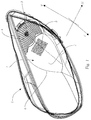
- Fig. 1 shows schematically a motor vehicle lighting device 1 according to the invention, which is installed in a motor vehicle headlight 2, wherein the motor vehicle headlight a plurality of lighting devices, such as Fig. 1 shows, may include.
- the motor vehicle lighting device 1 shown has a light source 3 and a light reflecting system consisting of a single reflector 4.
- a motor vehicle lighting device 2 even more optically relevant, but not shown, light imaging elements, such as screens and / or prisms and / or lenses and / or TIR optics and / or mirrors (especially micromirrors, micromirror arrays such as controllable DMD or DLP chips) and / or optical fibers, etc. have.
- a light source 3 for example, a simple Incandescent lamp, a (usually attached to a board, which may be attached, for example.
- LED light sources OLED light sources or a laser light source function.
- Reflectors can also be designed differently. For example, it can be a free-form reflector.
- the motor vehicle lighting device 1 generates a light beam which propagate (in the case of an activated light source) in the main emission direction Z of the motor vehicle lighting device 1, wherein at least a part of the light rays, preferably all light rays, is scattered by an optical structure 5 before the light rays from the motor vehicle headlight 2 exit and advised in front of the motor vehicle headlight 2.
- the optical structure 5 is disposed between the reflector 4 and a cover plate 6 of the motor vehicle headlight 2 and upstream of a motor vehicle lighting device 2, which motor vehicle lighting device as a direction indicator (in the main emission Z) is formed.
- the optical structure 5 is arranged on an inner side surface 7 of the cover disk 6.
- Fig. 2 represents a section of the lens 7 in perspective view.
- the optical structure 5 has a plurality of optical light-diffusing structural elements 50, each structural element having a protrusion 51.
- the structural elements 50 may be arranged periodically, for example on an imaginary quadrilateral grid 70, it being understood that other imaginary gratings, such as hexagonal, triangular, etc. may be used for the periodic arrangement of the structural elements 50.
- Each structural element 50 has an elevation 51, which in the in Fig.
- a tetrahedron with a curved, outwardly viewed from the tetrahedron curved surface 52 is formed.
- the structural elements may be different convex polyhedra, for example as hexahedra (see Fig. 3 ) be formed.
- Fig. 2a shows an enlarged perspective view of a tetrahedral structural element 50.
- the curved surface 52 of the tetrahedron may be formed, for example, ellipsoidal surface, with three straight edges a, b and c of the tetrahedron can correspond to half-axes of the ellipsoid.
- two of three half-axes of the ellipsoid or all half-axes of the ellipsoid can be the same, which in the latter case is a sphere section (spherical section).
- the curved surface 52 opposite of the tetrahedron edges a and b (c in this embodiment, the height of a structural element corresponding to) limited substantially planar surface 53 is disposed on the inner side surface 7 of the lens. 6
- the curved surface 52 faces the luminous flux 8 generated by the motor vehicle lighting device 1 and deflects the light incident thereon from the main radiation direction Z, ie the direction of propagation of the luminous flux generated by the motor vehicle lighting device 1.
- the remaining two surfaces of the tetrahedron form a Dieder (Zweiflächner) whose common edge is aligned substantially parallel to the main emission Z, but may also be inclined to Hauptabstrahlraum Z, for example, unwanted crosstalk (by avoiding the To avoid light leakage from the structural element by total reflection) between the structural elements, or to change the size of the curved surface 52.
- the dihedral angle D ie the angle between two facets of the Dieder, is in this embodiment substantially 90 °, and it is quite conceivable that another angle may be advantageous if, for example, the structural elements are not rectangular grid but hexagonal lattice or arranged triangular lattice ,
- the direction or directions in which the light is deflected (scattered) by respective structural elements may depend on the orientation of the structural element 50, in particular the orientation of the curved surface 52, the distance between the structural elements and the orientation of the common edge of the Depend on Dieder.
- FIG. 2a an enlarged tetrahedral structural element 50 in which the curved surface 52 is formed as Ellipsoidausschnitt.
- a horizontal section of the structural element 50 (FIG. Fig. 2b ) represents an ellipse sector, the length and curvature of which predetermines the above-mentioned angular range of the scattering in the horizontal direction.
- the orientation of the substantially planar surface 53 with respect to the main emission direction Z is a further parameter which influences the angular range.
- a vertical section (not shown) of the structural element 50 represents a further ellipse sector whose length and curvature influence the light scattering in an angular range in a vertically arranged plane (vertical direction).
- the light scattered by each structural element 50 is formed as an, for example, converging light beam. If the curved surface 52 were planar, the etendue of the light beam incident on the structural element would not be changed, ie the light beam would be deflected by the structural element without its expansion properties, convergence or divergence being affected.
- a horizontal section of the tetrahedral structural element 50 is shown, wherein two straight edges 53 ', 54' enclose a substantially right angle and are each arranged parallel to the main emission direction Z and to the horizontal H.
- Another arrangement of the straight edges is quite conceivable (see, eg Fig. 6, 6a, 6b and 7 ) and may be advantageous if the optical structure 5 is arranged obliquely with respect to the main emission direction Z.
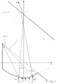
- Fig. 2b illustrates general idea of the refraction of light on a structural element 50 according to the invention.
- the section of the structural element is formed as an ellipse with two half-axes c 'and b'.
- the elliptical profile of the section of the curved, preferably ellipsoidal, surface has the advantage that the angle of refraction ⁇ '( t ) of the light beam 80 penetrating into the structural element depends on the point t at which the light beam 80 impinges on the light beam Structural element hits. If one now mentally moves the light beam 80 to the left or to the right (in the horizontal direction), then the refraction angle ⁇ '( t ) changes monotonically, in accordance with the elliptical course of the section of the curved surface, for example. Due to this monotonous dependence of the refraction angle ⁇ '( t ) on the point of incidence t of the light beam 8, as shown in FIG Fig.
- FIG. 2b is shown formed at the exit through the semi-axis b 'limited side (edge) 54' (at least horizontally) converging beam 8h, the maximum deflection angle is about 45 °.
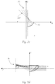
- the horizontally converging beam 8h is in Fig. 2c shown.
- the beam 8h may be formed as a diverging beam.
- Fig. 2d shows a vertically converging beam 8v. A vertical convergence or divergence of the beam emerging from the structural element 50 can then occur when the curved surface of the structural element is curved in the vertical direction V.
- the structural element 60 is formed as a hexahedron with a curved, for example ellipsoidal, facet 61.
- Such structural element 60 can be achieved, for example, by extruding the tetrahedral structural element 50.
- the facet is formed such that the hexahedron 60 is convex and has two triangular faces (each triangle having a curved side 62 ', 63') having facets 62, 63.
- the plan (five in total) facets are arranged essentially either vertically or horizontally.
- the substantially facet facet 64 lying opposite the curved facet can, for example, be arranged perpendicular to the main emission direction Z and on the inner side surface, not shown here, of the cover lens of a motor vehicle headlight. In this case, the substantially entire light penetrated by the curved facet 61 exits through this substantially planar facet 64 again.
- the curved facet 61 is formed to diffuse the incident light in the form of a light beam 8 'converging both vertically and horizontally. But it is also conceivable that the curved facet 61 may be formed such that the light beam 8 'diverges vertically and horizontally or converges vertically and horizontally diverges or vertically diverges and converges horizontally.
- the curved facet 61 is formed such that the incident light beam 8 is not deflected in the vertical direction. This is possible, for example, when the curved facet 61 is formed as a cylinder surface cutout of, for example, a straight elliptical cylinder with the axis of the cylinder vertically arranged.
- the curved facet 61 of the hexahedron 60 or the above-described tetrahedron 50 or a structural element formed as a polyhedron may be formed such that the structural element detects the incident light to the left and / or to the right of the main emission direction can divert.
- the curved facet of the tetrahedral, pentahedral, hexagonal, or generally polyhedral follows a different course than the course of an ellipsoid.
- the curved facet can, for example, follow the course of an exponential function. It is particularly advantageous that the curved facet has the same direction of curvature substantially in all its points.
- ellipsoid also includes an ellipsoid of revolution and a sphere (a spherical surface). So it is e.g. conceivable that structural elements are designed as spherical segments or spherical segment cutouts.
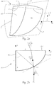
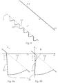
- Fig. 4 shows the required by ECE regulation R6 horizontal radiating cone 9 a direction indicator 2 in a plan view. It is about a mounted on a right side of a front portion of a vehicle direction indicator. For simplicity of illustration, the main radiation direction Z is shown coincident with the vehicle longitudinal axis.
- the ECE regulation R6 stipulates that the emission cone should extend to the left (inside the vehicle) up to 45 ° and to the right (outside the vehicle) up to 80 °. In a direction indicator mounted on a left side of a front portion of a vehicle, the emission cone will be mirrored with respect to the vehicle longitudinal axis.
- Fig. 5 shows an enlarged plan view of a section of the lens 6, which end plate 6 obliquely (not orthogonal, for example, inclined by 40 °) to the main emission Z (the propagation direction of the light beam 8) of Motor vehicle lighting device 1 is.
- a structural element 50, 60 is arranged, whose curved surface faces the light beam and is curved against the emission direction.
- the substantially planar surface of the structural element arranged on the inner side surface 7 is likewise arranged obliquely to the main emission direction.
- the size of the structural element 50, 60 and the curvature of its curved surface are adapted to the inclination of the lens in such a way that does not exit the entire incident on the structural element 50, 60 light 8 from the lens.
- the light beam entering the structure element 50, 60 at point t2 does not exit the lens due to total reflection at the lens outer surface .
- Figures 6, 6a and 6b show further preferred embodiments of the structural elements.
- the straight edges 53 ', 54' do not enclose a right angle.
- the edge 53 ' which is not arranged on the optical structure 5 and coincides with the curved side at a corner point 10 is arranged substantially parallel to the main emission direction Z ( Fig. 6 ).
- the edge 53 ' which is not arranged on the optical structure, is arranged in such a way that it has a small positive skew angle ⁇ (approximately 0 ° to 10 °, preferably 2 ° to 4 °) from the main emission direction Z Main emission direction Z forms ( Fig. 6b ).
- ⁇ approximately 0 ° to 10 °, preferably 2 ° to 4 °
- Main emission direction Z forms ( Fig. 6b ).
- each structural element 501, 502 can be arranged per one base area 701 of a rectangular grid 70.
- the grid 70 may be hexagonal or triangular, for example.
- the structural elements 501, 502 are such arranged that a flat (flat) facet 501 'of a first structural element 501 is arranged congruent to a planar facet 502' of a second arranged on the same base 701 structural element 502 and with the planar facet 501 'of the first structural element 501 is merge.
- a flat (flat) facet 501 'of a first structural element 501 is arranged congruent to a planar facet 502' of a second arranged on the same base 701 structural element 502 and with the planar facet 501 'of the first structural element 501 is merge.
- the first structural elements 501 are combined with the second structural elements 502 such that the planar facet 501 'of each first structural element 501 is arranged on the planar facet 502' of the second structural element 502 merged with the first structural element 501 and covers it substantially completely.
- the first structural elements 501 and the second structural elements 502 can be displaced relative to one another in the vertical direction V and / or in the horizontal direction H. It can be particularly advantageous if the curved surfaces 501 ", 502" of the structure elements arranged in pairs are turned away from one another but curved in the same direction.
- each pair of the structural elements 501, 502 simultaneously expands the beam (light beam) incident on the optical structure to the left and to the right of the beam incident axis Z, which may coincide with the main radiation direction and / or the vehicle longitudinal axis.
- the structural elements arranged in pairs on a base surface 701 can also be arranged differently from one another.
- the curved surfaces 501 ", 502" may be curved in different directions so that the flat surfaces 501 ', 502' are no longer mergable.
- an optical structure has both the structural elements 501 incident on the optical structure with respect to the beam incidence axis Z and the structural elements 501 incident on the optical structure with respect to the beam incidence axis Z ,
- these structural elements can be arranged differently from one another, for example in such a way that the production process of the optical structure is improved.
Landscapes
- Engineering & Computer Science (AREA)
- General Engineering & Computer Science (AREA)
- Mechanical Engineering (AREA)
- Non-Portable Lighting Devices Or Systems Thereof (AREA)
- Lighting Device Outwards From Vehicle And Optical Signal (AREA)
Abstract
Kraftfahrzeugbeleuchtungsvorrichtung (1) für einen Kraftfahrzeugscheinwerfer (2) umfassend zumindest eine Lichtquelle (3), ein der zumindest einen Lichtquelle (3) zugeordnetes optisches Lichtabbildungssystem (4), welches dazu eingerichtet ist, das von der zumindest einen Lichtquelle (3) erzeugtes Licht in Form einer Lichtverteilung vor die Kraftfahrzeugbeleuchtungsvorrichtung (1) abzubilden, und eine optische Struktur (5), die dazu eingerichtet ist, die Lichtverteilung zu einer modifizierten Lichtverteilung zu modifizieren, und eine Mehrzahl optischer lichtstreuender Strukturelemente (50, 60) aufweist, wobei jedes Strukturelement eine Erhebung (51) aufweist, welche Erhebung (51) das von der zumindest einen Lichtquelle (3) erzeugte und auf die Erhebung (51) mithilfe des zumindest einen Lichtabbildungssystems (4) gelenkte Licht, in zumindest einer Raumebene in zumindest eine Richtung umlenkt, wobei die optische Struktur (5) dem zumindest einen optischen Lichtabbildungssystem (4) in die Hauptabstrahlrichtung (Z) nachgeordnet oder ein Teil des optischen Lichtabbildungssystems (4) ist, die Erhebung (51) konvex ausgebildet ist, zumindest eine gekrümmte Fläche (52, 61) und eine der gekrümmten Fläche gegenüberliegende im Wesentlichen plane Fläche (53, 64) aufweist, welche gekrümmte Fläche (52, 61) dem von der zumindest einen Lichtquelle erzeugten und auf das Strukturelement (50, 60) mithilfe des zumindest einen Lichtabbildungssystems (4) gelenkten Licht (8, 80) zugewandt ist, und die zumindest eine Raumebene eine Horizontalebene ist, und die modifizierte Lichtverteilung in der Horizontalebene aufgeweitet ist.Motor vehicle lighting device (1) for a motor vehicle headlight (2) comprising at least one light source (3), an optical light imaging system (4) associated with the at least one light source (3) and configured to light the light generated by the at least one light source (3) Form an optical structure (5) which is adapted to modify the light distribution to a modified light distribution, and a plurality of optical light-diffusing structural elements (50, 60), each structural element having a Survey (51), which elevation (51) of the at least one light source (3) generated and on the survey (51) using the at least one light imaging system (4) deflected light in at least one spatial plane in at least one direction deflects the optical structure (5) the at least one optical light imaging system (4) in the Main emission (Z) or a part of the optical light imaging system (4), the elevation (51) is convex, at least one curved surface (52, 61) and the curved surface opposite substantially planar surface (53, 64) which curved surface (52, 61) faces the light (8, 80) generated by the at least one light source and directed onto the structural element (50, 60) by means of the at least one light imaging system (4), and the at least one spatial plane is a horizontal plane is, and the modified light distribution is widened in the horizontal plane.
Description
Die Erfindung betrifft eine Kraftfahrzeugbeleuchtungsvorrichtung für einen Kraftfahrzeugscheinwerfer umfassend zumindest eine Lichtquelle, ein der zumindest einen Lichtquelle zugeordnetes optisches Lichtabbildungssystem, welches dazu eingerichtet ist, das von der zumindest einen Lichtquelle erzeugtes Licht in Form einer Lichtverteilung, beispielsweise einer Signallicht-Lichtverteilung oder einer Positionslicht-Lichtverteilung, vor die Kraftfahrzeugbeleuchtungsvorrichtung abzubilden, und eine optische Struktur, die dazu eingerichtet ist, die Lichtverteilung zu einer modifizierten Lichtverteilung, insbesondere zu einer modifizierten Signallicht-Lichtverteilung, zu modifizieren, und eine Mehrzahl optischer lichtstreuender Strukturelemente aufweist, wobei jedes Strukturelement eine Erhebung aufweist, welche Erhebung das von der zumindest einen Lichtquelle erzeugte und auf die Erhebung mithilfe des zumindest einen Lichtabbildungssystems gelenkte Licht, in zumindest einer Raumebene in zumindest eine Richtung umlenkt.The invention relates to a motor vehicle lighting device for a motor vehicle headlight comprising at least one light source, an optical light imaging system associated with the at least one light source and configured to emit the light generated by the at least one light source in the form of a light distribution, for example a signal light light distribution or a position light light distribution to image in front of the motor vehicle lighting device, and an optical structure adapted to modify the light distribution to a modified light distribution, in particular to a modified signal light light distribution, and a plurality of optical light scattering structural elements, each structural element having a bump, which Survey the light generated by the at least one light source and directed to the survey using the at least one light imaging system, in at least one spatial level in at least one direction deflects.
Außerdem betrifft die Erfindung einen Kraftfahrzeugscheinwerfer mit zumindest einer solchen Kraftfahrzeugbeleuchtungsvorrichtung.Moreover, the invention relates to a motor vehicle headlight with at least one such motor vehicle lighting device.
Darüber hinaus betrifft die Erfindung ein Kraftfahrzeug mit zumindest einem solchen Kraftfahrzeugscheinwerfer.Moreover, the invention relates to a motor vehicle with at least one such motor vehicle headlight.
Kraftfahrzeugbeleuchtungsvorrichtungen mit optischen Strukturen sind im KFZ-Bau bekannt. Sie können beispielsweise einer Aufweichung der Hell-Dunkel-Grenze dienen. Darüber hinaus offenbart der Stand der Technik optische Strukturen in unterschiedlichen Formen. Dabei können die optischen Strukturen aus einer Mehrzahl einzelner Strukturelemente bestehen und an einer Oberfläche eines Kraftfahrzeugscheinwerferelements, beispielsweise einer Linse, eines Reflektors, einer Abschlussscheibe usw. angeordnet sein. Alternativ können solche optischen Strukturen durch spezielle Verarbeitung der Oberfläche eines Kraftfahrzeugscheinwerferelements, beispielsweise durch Aufrauhung durch Sandstrahlen, angebracht werden.Automotive lighting devices with optical structures are known in motor vehicle construction. For example, they can serve to soften the cut-off line. Moreover, the prior art discloses optical structures in various forms. The optical structures may consist of a plurality of individual structural elements and may be arranged on a surface of a motor vehicle headlight element, for example a lens, a reflector, a lens, etc. Alternatively, such optical structures can be applied by special processing of the surface of a motor vehicle headlamp element, for example by roughening by sandblasting.
In den internationalen Anmeldungen
Alternativ offenbart die Anmeldung
Im oben beschriebenen Stand der Technik werden Probleme der Hauptbeleuchtung (hauptsächlich Abblendlicht- und Fernlichtfunktionen) eines Fahrzeugs behandelt. Dabei ist stets auf die gesetzlich vorgeschriebenen Normen abzustellen, welche vorschreiben wieviel Licht in welche Richtungen gestreut werden darf. Deshalb sind die oben beschriebenen optischen Strukturen (Strukturelemente) derart ausgebildet, dass das Licht nur unter relativ kleinen Winkeln, und im Wesentlichen in einer vertikalen Ebene, bezüglich der Hauptabstrahlrichtung des Kraftfahrzeugscheinwerfers gestreut wird. Andernfalls wären die mit breit streuenden optischen Strukturen ausgestatteten Kraftfahrzeugbeleuchtungsvorrichtungen wegen strikter gesetzlicher die Hauptlichtfunktionen eines Kraftfahrzeugscheinwerfers betreffender Normen nicht zugelassen.In the prior art described above, problems of the main lights (mainly low beam and high beam functions) of a vehicle are dealt with. It is always necessary to focus on the legally prescribed standards, which prescribe how much light may be scattered in which directions. Therefore, the above-described optical structures (structural elements) are formed such that the light is scattered only at relatively small angles, and substantially in a vertical plane, with respect to the main radiation direction of the vehicle headlamp. Otherwise, the motor vehicle lighting devices equipped with wide-spread optical structures would not be admitted due to strict legal standards concerning the main light functions of a motor vehicle headlight.
Darüber hinaus, spielt in der Entwicklung von Hauptscheinwerfern das Design eine immer stärkere Rolle. Diese Designs stehen aber immer wieder im Konflikt mit den gesetzlichen Anforderungen an die Lichtfunktionen. Besonders im Bereich der Signallichtfunktionen wird es immer schwieriger, die bei bspw. Fahrtrichtungsanzeigern und Positionslicht geforderten großen Winkelbereiche von bis zu 160° auszuleuchten.In addition, design plays an increasingly important role in the development of headlamps. However, these designs repeatedly conflict with the legal requirements for lighting functions. Particularly in the field of signal light functions, it is becoming increasingly difficult to illuminate the large angular ranges of up to 160 ° required for, for example, direction indicators and position light.
Um große Winkelbereiche auszuleuchten können, wie in der Anmeldung
Darüber hinaus verursachen zusätzliche optische Elemente vor den Reflektoren (siehe z.B.
Außerdem streuen die in der Anmeldung
Die Aufgabe der vorliegenden Erfindung ist es deshalb eine Kraftfahrzeugbeleuchtungsvorrichtung für einen Kraftfahrzeugscheinwerfer eines Kraftfahrzeugs zu schaffen, die die oben beschriebenen Nachteile der Kraftfahrzeugbeleuchtungsvorrichtungen nach dem Stand der Technik überwindet und eine optische Struktur aufweist, welche trotz einer geringen Größe der Strukturelemente eine gerichtete Lichtumlenkung zumindest in einer horizontalen Ebene in einem großen Winkelbereich ermöglicht.The object of the present invention is therefore to provide a motor vehicle lighting device for a motor vehicle headlight of a motor vehicle, which overcomes the above-described disadvantages of motor vehicle lighting devices according to the prior art and has an optical structure which despite a small size of the structural elements directed light deflection at least in one horizontal plane in a wide angle range allows.
Diese Aufgabe wird mit einer eingangs erwähnten Kraftfahrzeugbeleuchtungsvorrichtung erfindungsgemäß dadurch gelöst, dass die optische Struktur dem optischen Lichtabbildungssystem in die Hauptabstrahlrichtung nachgeordnet oder ein Teil des optischen Lichtabbildungssystems ist, die Erhebung konvex ausgebildet ist, zumindest eine gekrümmte Fläche und eine der gekrümmten Fläche gegenüberliegende im Wesentlichen plane Fläche aufweist, welche gekrümmte Fläche dem von der zumindest einen Lichtquelle erzeugten und auf das Strukturelement mithilfe des zumindest einen Lichtabbildungssystems gelenkten Licht zugewandt ist, und die zumindest eine Raumebene eine Horizontalebene ist, und die modifizierte Lichtverteilung in der Horizontalebene aufgeweitet ist.This object is achieved with a motor vehicle lighting device mentioned above according to the invention that the optical structure of the optical light imaging system downstream in the main emission or part of the optical light imaging system, the survey is convex, at least one curved surface and the curved surface opposite substantially planar Surface, which curved surface faces the light generated by the at least one light source and directed to the structural element by means of the at least one light imaging system, and the at least one spatial plane is a horizontal plane, and the modified light distribution is widened in the horizontal plane.
Dabei beziehen sich die Begriffe "horizontal" und "vertikal" auf einen in ein Fahrzeug eingebauten Scheinwerfer.The terms "horizontal" and "vertical" refer to a built-in vehicle headlights.
Hinsichtlich einer gezielten Ablenkung des Lichts, kann es zweckmäßig sein, wenn die gekrümmte Fläche ellipsoidflächenförmig ausgebildet ist.With regard to a targeted deflection of the light, it may be expedient if the curved surface is formed ellipsoidal surface.
Hinsichtlich des Herstellungsverfahrens kann es vorteilhaft sein, wenn die Erhebung konvex polyederförmig ausgebildet ist.With regard to the manufacturing method, it may be advantageous if the elevation is convex polyhedron-shaped.
Um eine gezielte Lichtbündelausdehnung eines auf jedes Strukturelement einfallenden Lichtbündels zu erzielen kann es zweckdienlich sein, wenn die Erhebung konvex tetraederförmig ausgebildet ist und genau eine gekrümmte Fläche aufweist.In order to achieve a targeted light beam expansion of an incident light beam on each structural element, it may be expedient if the elevation is formed convex tetrahedral and exactly has a curved surface.
Um Ablenkung von auf Strukturelemente einfallender Lichtstrahlen hinsichtlich unterschiedlicher Raumebenen zu beeinflussen, kann es vorteilhaft sein, wenn die Erhebung konvex hexaederförmig, insbesondere würfelförmig, ausgebildet ist und genau eine gekrümmte Fläche aufweist.In order to influence the deflection of light rays incident on structural elements with respect to different spatial planes, it may be advantageous if the elevation is convex hexahedral, in particular cube-shaped, and has exactly one curved surface.
Ein Strukturelement, welches eine hexaederförmig ausgebildete Erhebung aufweist, wobei die Erhebung genau eine gekrümmte (gegen die Hauptabstrahlrichtung der Kraftfahrzeugbeleuchtungsvorrichtung gewölbte) ellipsoidflächenförmige Fläche umfasst, bringt den Vorteil, dass die Krümmung der gekrümmten Fläche unterschiedliche Werte je nach Raumrichtung annehmen kann. So ist es denkbar, dass die gekrümmte Fläche als Teil eines Zylinders (eine Zylindermantelfläche) ausgebildet ist und dergestalt angeordnet ist, dass die Krümmung in vertikaler Richtung verschwindend klein ist (die Zylinderachse verläuft vertikal). In diesem Fall kann die Ablenkung des Lichts in vertikaler Richtung vermieden werden.A structural element which has a hexahedron-shaped elevation, wherein the elevation comprises precisely a curved (curved against the main emission direction of the motor vehicle lighting device) ellipsoidal surface, has the advantage that the curvature of the curved surface can assume different values depending on the spatial direction. Thus, it is conceivable that the curved surface is formed as part of a cylinder (a cylindrical surface) and is arranged such that the curvature in the vertical direction is vanishingly small (the cylinder axis is vertical). In this case, the deflection of the light in the vertical direction can be avoided.
Weiterhin kann es z.B. hinsichtlich Verwirklichung einer besseren Signallicht-Funktion vorteilhaft sein, wenn die Erhebung ellipsoidsegmentförmig ausgebildet ist.Furthermore, it may e.g. be advantageous in terms of achieving a better signal light function when the survey is formed ellipsoid segment-shaped.
Darüber hinaus kann es zweckmäßig sein, wenn die Erhebung als eine abgeschnittene ellipsoidsegmentförmige Erhebung ausgebildet ist, wobei die Schnittebene hinsichtlich der planen Fläche geneigt ist.In addition, it may be expedient if the elevation is formed as a truncated ellipsoid segment-shaped elevation, wherein the sectional plane is inclined with respect to the plane surface.
Hinsichtlich der Erfüllung der gesetzlichen Vorschriften und Normen (beispielsweise ECE, SAE, CCC) kann es vorteilhaft sein, wenn die gekrümmte Fläche der Strukturelemente derart ausgebildet ist, dass jedes Strukturelement das Licht bei einer in ein Kraftfahrzeug eingebauten Kraftfahrzeugbeleuchtungsvorrichtung in alle Richtungen in einem Winkelbereich von 0° bis 80° (z.B. bei Motorrädern), insbesondere von 0° bis 45°, fahrzeuginnenseitig und von 0° bis 80° fahrzeugaußenseitig von der Hauptabstrahlrichtung der Kraftfahrzeugbeleuchtungsvorrichtung streut.With regard to the fulfillment of the legal regulations and standards (for example ECE, SAE, CCC), it may be advantageous if the curved surface of the structural elements is such is formed, that each structural element the light in a built in a motor vehicle motor vehicle lighting device in all directions in an angular range of 0 ° to 80 ° (eg motorcycles), in particular from 0 ° to 45 °, vehicle inside and 0 ° to 80 ° vehicle outside scatters from the main radiation direction of the automotive lighting device.
Die verwendeten Begriffe "fahrzeuginnenseitig" und "fahrzeugaußenseitig" beziehen sich im Zusammenhang mit der vorliegenden Erfindung auf einen eingebauten Zustand der Kraftfahrzeugbeleuchtungsvorrichtung in ein Kraftfahrzeug.The terms "vehicle inside" and "vehicle outside" used in the context of the present invention refer to an installed state of the motor vehicle lighting device in a motor vehicle.
In dem Fall, wenn die optische Struktur Strukturelemente mit unterschiedlichen Streueigenschaften aufweist, kann es hinsichtlich der Erfüllung der gesetzlichen Vorschriften und Normen (beispielsweise ECE, SAE, CCC) vorteilhaft sein, wenn zumindest ein Teil der Strukturelemente derart angeordnet und/oder ausgebildet ist, dass jedes Strukturelement des zumindest einen Teils das auf dieses Strukturelement einfallende Licht in alle Richtungen in einem Winkelbereich von 0° bis 80° rechts oder links von der Hauptabstrahlrichtung der Kraftfahrzeugbeleuchtungsvorrichtung, vorzugsweise von einer Kraftfahrzeuglängsachse, streut, und zumindest ein weiterer Teil der Strukturelemente derart angeordnet und/oder ausgebildet ist, dass jedes Strukturelement des zumindest einen weiteren Teils das auf dieses Strukturelement einfallende Licht in alle Richtungen in einem Winkelbereich von 0° bis 80° (z.B. bei Motorrädern), insbesondere von 0° bis 45°, links oder rechts von der Hauptabstrahlrichtung der Kraftfahrzeugbeleuchtungsvorrichtung streut.In the case where the optical structure has structural elements with different scattering properties, it can be advantageous in terms of compliance with the legal regulations and standards (for example ECE, SAE, CCC) if at least a part of the structural elements is arranged and / or constructed such that each structural element of the at least one part which scatters light incident on this structural element in all directions in an angular range of 0 ° to 80 ° to the right or left of the main emission direction of the motor vehicle lighting device, preferably from a motor vehicle longitudinal axis, and at least one further part of the structural elements arranged and is formed, that each structural element of the at least one further part of the incident on this structural element light in all directions in an angular range of 0 ° to 80 ° (eg motorcycles), in particular from 0 ° to 45 °, left or right of the Hauptabstrahlrichtun g of the motor vehicle lighting device scatters.
Hinsichtlich der Möglichkeit, andere Lichtfunktionen mit der erfindungsgemäßen Kraftfahrzeugbeleuchtungsvorrichtung zu realisieren, kann es vorteilhaft sein, wenn die Strukturelemente derart angeordnet und/oder ausgebildet sind, dass das auf die Strukturelemente einfallende Licht in einer weiteren, vorzugsweise vertikal angeordneten, Raumebene in zumindest eine Richtung, insbesondere in alle Richtungen in einem Winkelbereich von 0° bis 45°, vorzugsweise von 0° bis 15°, in einer Vertikalebene nach oben von der Hauptabstrahlrichtung der Kraftfahrzeugbeleuchtungsvorrichtung, streut und die modifizierte Lichtverteilung in dieser weiteren, vorzugsweise vertikal ausgerichteten/angeordneten, Raumebene aufgeweitet ist.With regard to the possibility of realizing other light functions with the motor vehicle lighting device according to the invention, it can be advantageous if the structural elements are arranged and / or formed in such a way that the light incident on the structural elements in a further, preferably vertically arranged, spatial plane in at least one direction, in particular in all directions in an angle range of 0 ° to 45 °, preferably from 0 ° to 15 °, in a vertical plane upwards from the main emission of the motor vehicle lighting device, scatters and widens the modified light distribution in this further, preferably vertically aligned / arranged, spatial plane is.
Die verwendeten Begriffe "nach oben" und "nach unten" beziehen sich im Zusammenhang mit der vorliegenden Erfindung auf einen eingebauten Zustand derThe terms "up" and "down" used in the context of the present invention refer to a built-in state of
Kraftfahrzeugbeleuchtungsvorrichtung in ein Kraftfahrzeug.Motor vehicle lighting device in a motor vehicle.
Eine Umlenkung des Lichts in einer weiteren Raumebene, beispielsweise in einer Vertikalebene, kann mithilfe von Strukturelementen erzielt werden, die eine Erhebung aufweisen, deren vertikaler Schnitt eine endliche Krümmung aufweist. Beispiele von solchen Erhebungen sind z.B. in
Hinsichtlich der Minimierung der Lichtverluste durch die optische Struktur kann es zweckmäßig sein, wenn jedes Strukturelement derart ausgebildet ist, dass das im Wesentlichen gesamte in das Strukturelement durch die gekrümmte Fläche eintretende Licht aus dem Strukturelement durch die der gekrümmten Fläche gegenüberliegende im Wesentlichen plane Fläche austritt.With regard to the minimization of the light losses through the optical structure, it may be expedient if each structural element is formed such that the substantially entire light entering the structural element through the curved surface exits the structural element through the substantially planar surface opposite the curved surface.
Um Entstehung von Zusatzkosten durch Verwendung von kostenintensiven Fräsköpfen, beispielsweise diamantbestückten Fräsköpfen, zu vermeiden, kann er zweckdienlich sein, wenn jedes Strukturelement eine charakteristische Länge von 100 Mikrometer aufweist.To avoid incurring additional costs by using costly milling heads, such as diamond tipped cutter heads, it may be convenient if each feature has a characteristic length of 100 microns.
Die oben genannte Aufgabe ist außerdem mit einem Kraftfahrzeugscheinwerfer erfindungsgemäß dadurch gelöst, dass die optische Struktur an zumindest einem Teil einer Innenseitenoberfläche einer Abschlussscheibe des Kraftfahrzeugscheinwerfers einem Fahrtrichtungsanzeiger und/ oder einem Positionslicht-Modul vorgelagert ist und die Lichtverteilung als eine Signallicht-Lichtverteilung ausgebildet ist.The above object is also achieved with a motor vehicle headlamp according to the invention that the optical structure is disposed on at least a part of an inner side surface of a lens of the motor vehicle headlight upstream of a direction indicator and / or a position light module and the light distribution is formed as a signal light light distribution.
Die Erfindung samt weiteren Vorteilen ist im Folgenden anhand beispielhafter Ausführungsformen näher erläutert, die in der Zeichnung veranschaulicht sind. In dieser zeigt
-
Fig. 1 eine erfindungsgemäße Kraftfahrzeugbeleuchtungsvorrichtung, welche in einen Kraftfahrzeugscheinwerfer eingebaut ist; -
Fig. 2 einen Ausschnitt einer eine optische Struktur aufweisenden Abschlussscheibe eines Kraftfahrzeugscheinwerfers in perspektivischer Ansicht; -
Fig. 2a eine vergrößerte perspektivische Ansicht eines tetraederförmigen Strukturelements; -
Fig. 2b einen horizontalen Schnitt des Strukturelements derFig. 2a ; -
Fig. 2c vertikalen Schnitt einer Lichtstreuung an dem Strukturelement derFig. 2a ; -
Fig. 2d horizontalen Schnitt einer Lichtstreuung an dem Strukturelement derFig. 2a ; -
Fig. 3 eine vergrößerte perspektivische Ansicht eines hexaederförmigen Strukturelements; -
Fig. 4 einen durch die ECE-Regelung R6 geforderten horizontalen Abstrahlkegel; -
Fig. 5 eine vergrößerte Draufsicht eines Ausschnitts einer schräg zu einer Hauptabstrahlrichtung der Kraftfahrzeugbeleuchtungsvorrichtung angeordneten und eine optische Struktur aufweisenden Abschlussscheibe; -
Fig. 6, 6a und 6b Anordnungen der geraden Flächen der Strukturelemente hinsichtlich einer Hauptabstrahlrichtung, und -
Fig. 7 ein Ausschnitt einer optischen Struktur mit jeweils zwei dicht nebeneinander Angeordneten Strukturelementen.
-
Fig. 1 a motor vehicle lighting device according to the invention, which is installed in a motor vehicle headlight; -
Fig. 2 a detail of an optical structure having a lens of a motor vehicle headlight in a perspective view; -
Fig. 2a an enlarged perspective view of a tetrahedral structural element; -
Fig. 2b a horizontal section of the structural element ofFig. 2a ; -
Fig. 2c vertical section of a light scattering on the structural element ofFig. 2a ; -
Fig. 2d horizontal section of a light scattering on the structural element of theFig. 2a ; -
Fig. 3 an enlarged perspective view of a hexahedral structural element; -
Fig. 4 a horizontal radiating cone required by ECE Regulation R6; -
Fig. 5 an enlarged plan view of a section of an obliquely arranged to a main emission direction of the motor vehicle lighting device and having an optical structure end lens; -
Fig. 6, 6a and 6b Arrangements of the straight surfaces of the structural elements with respect to a main emission direction, and -
Fig. 7 a section of an optical structure, each with two closely juxtaposed structural elements.
Zunächst wird auf
Bei einer weiteren bevorzugten Ausführungsform der vorliegenden Erfindung ist die optische Struktur 5 an einer Innenseitenoberfläche 7 der Abschlussscheibe 6 angeordnet.
Unter dem Begriff Ellipsoid wird in Zusammenhang mit der vorliegenden Erfindung eine Punktmenge verstanden, die die folgende Gleichung erfüllt ![]()
![]()
Dabei können zwei von drei Halbachsen des Ellipsoids oder alle Halbachsen des Ellipsoids gleich sein, wobei es sich im letzten Fall um einen Sphärenabschnitt (Kugelabschnitt) handelt. Die der gekrümmten Fläche 52 gegenüberliegende von den Tetraederkanten a und b (c kann bei dieser Ausführungsform der Höhe eines Strukturelementes entsprechen) begrenzte im Wesentlichen plane Fläche 53 ist an der Innenseitenoberfläche 7 der Abschlussscheibe 6 angeordnet.In this case, two of three half-axes of the ellipsoid or all half-axes of the ellipsoid can be the same, which in the latter case is a sphere section (spherical section). The
Die gekrümmte Fläche 52 ist der dem von der Kraftfahrzeugbeleuchtungsvorrichtung 1 erzeugten Lichtstrom 8 zugewandt und lenkt das auf sie einfallende Licht von der Hauptabstrahlrichtung Z, d.h. der Richtung der Ausbreitung des von der Kraftfahrzeugbeleuchtungsvorrichtung 1 erzeugten Lichtstroms, ab. Die restlichen zwei Flächen des Tetraeders (die restlichen zwei Facetten) bilden einen Dieder (Zweiflächner), dessen gemeinsame Kante im Wesentlichen parallel zur Hauptabstrahlrichtung Z ausgerichtet ist, die aber auch geneigt zur Hauptabstrahlrichtung Z sein kann, um bspw. unerwünschtes Übersprechen (durch Vermeiden des Lichtaustritts aus dem Strukturelement mittels Totalreflexion) zwischen den Strukturelementen zu vermeiden, oder die Größe der gekrümmten Fläche 52 zu ändern. Der Diederwinkel D, d.h. der Winkel zwischen zwei Facetten des Dieders, beträgt in diesem Ausführungsbeispiel im Wesentlichen 90°, wobei es durchaus vorstellbar ist, dass ein anderer Winkel von Vorteil sein kann, wenn bspw. die Strukturelemente nicht rechteckgittermäßig sondern hexagonalgittermäßig oder dreieckgittermäßig angeordnet sind.The
Die Richtung bzw. Richtungen, in welche das Licht von jeweiligen Strukturelementen umgelenkt (gestreut) wird, kann von der Orientierung des Strukturelements 50, insbesondere von der Orientierung der gekrümmten Fläche 52, von dem Abstand zwischen den Strukturelementen und von der Ausrichtung der gemeinsamen Kante des Dieders abhängen.The direction or directions in which the light is deflected (scattered) by respective structural elements may depend on the orientation of the
Um den Winkelbereich bestimmen zu können, in den jedes einzelne Strukturelement 50 das einfallende Licht streut, ist es vorteilhaft, den Verlauf der gekrümmten Fläche zu wissen. Wie oben erwähnt zeigt
In
Bei der in
Es soll an dieser Stelle angemerkt sein, dass die gekrümmte Facette 61 des Hexaeders 60 oder des oben beschriebenen Tetraeders 50 oder eines als ein Polyeder ausgebildeten Strukturelements derart ausgebildet sein kann, dass das Strukturelement das einfallende Licht nach links und/ oder nach rechts von der Hauptabstrahlrichtung umlenken kann.It should be noted at this point that the
Darüber hinaus ist es denkbar, dass die gekrümmte Facette des Tetra-, Penta-, Hexa- oder im Allgemeinen des Polyeders einem anderen Verlauf als dem Verlauf eines Ellipsoids folgt. Die gekrümmte Facette kann bspw. dem Verlauf einer Exponentialfunktion folgen. Vorteilhaft ist vor allem, dass die gekrümmte Facette im Wesentlichen in allen ihren Punkten die gleiche Krümmungsrichtung aufweist.Moreover, it is conceivable that the curved facet of the tetrahedral, pentahedral, hexagonal, or generally polyhedral follows a different course than the course of an ellipsoid. The curved facet can, for example, follow the course of an exponential function. It is particularly advantageous that the curved facet has the same direction of curvature substantially in all its points.
Anschließend soll hier hervorgehoben werden, dass der Begriff Ellipsoid auch ein Rotationsellipsoid und eine Sphäre (eine Kugeloberfläche) miteinschließt. So ist es z.B. vorstellbar dass Strukturelemente als Kugelsegmente oder Kugelsegmentausschnitte ausgebildet sind.Subsequently, it should be emphasized here that the term ellipsoid also includes an ellipsoid of revolution and a sphere (a spherical surface). So it is e.g. conceivable that structural elements are designed as spherical segments or spherical segment cutouts.
Die Größe des Strukturelements 50, 60 und die Krümmung seiner gekrümmten Fläche sind an die Schräglage der Abschlussscheibe derart angepasst, das nicht das gesamte auf das Strukturelement 50, 60 einfallende Licht 8 aus der Abschlussscheibe austritt. Der an dem Punkt t2 in das Strukturelement 50, 60 eintretende Lichtstrahl tritt aus der Abschlussscheibe aufgrund einer Totalreflexion an der Abschlussscheibenaußenoberfläche nicht aus. Dadurch kann man bei beliebigen Schräglagen der Abschlussscheibe und beliebigen Pfeilungen, d.h. der Position der Lichtquelle bezüglich der Kraftfahrzeugkarosserieteilen, des Kraftfahrzeugscheinwerfers im in ein Kraftfahrzeug eingebauten Zustand einen vorgegebenen Abstrahlkegel der Kraftfahrzeugbeleuchtungsvorrichtung 1 erreichen.The size of the
Bei einer besonders günstigen in
Darüber hinaus ist es denkbar, dass eine optische Struktur sowohl die das auf die optische Struktur einfallende Strahlenbündel bezugnehmend auf die Strahleinfallachse Z nach rechts aufweitenden Strukturelemente 501 als auch die das auf die optische Struktur einfallende Strahlenbündel bezugnehmend auf die Strahleinfallachse Z nach links aufweitenden Strukturelemente 502 aufweist. Dabei können diese Strukturelemente unterschiedlich zueinander angeordnet sein, beispielsweise dergestalt, dass der Herstellungsprozess der optischen Struktur verbessert wird.Moreover, it is conceivable that an optical structure has both the
Claims (15)
Priority Applications (2)
| Application Number | Priority Date | Filing Date | Title |
|---|---|---|---|
| EP16166879.3A EP3239593B1 (en) | 2016-04-25 | 2016-04-25 | Vehicular illumination device |
| CN201710269933.4A CN107314319B (en) | 2016-04-25 | 2017-04-24 | Lighting device for motor vehicle |
Applications Claiming Priority (1)
| Application Number | Priority Date | Filing Date | Title |
|---|---|---|---|
| EP16166879.3A EP3239593B1 (en) | 2016-04-25 | 2016-04-25 | Vehicular illumination device |
Publications (2)
| Publication Number | Publication Date |
|---|---|
| EP3239593A1 true EP3239593A1 (en) | 2017-11-01 |
| EP3239593B1 EP3239593B1 (en) | 2021-12-22 |
Family
ID=55862564
Family Applications (1)
| Application Number | Title | Priority Date | Filing Date |
|---|---|---|---|
| EP16166879.3A Active EP3239593B1 (en) | 2016-04-25 | 2016-04-25 | Vehicular illumination device |
Country Status (2)
| Country | Link |
|---|---|
| EP (1) | EP3239593B1 (en) |
| CN (1) | CN107314319B (en) |
Cited By (2)
| Publication number | Priority date | Publication date | Assignee | Title |
|---|---|---|---|---|
| CN114207350A (en) * | 2019-08-14 | 2022-03-18 | Zkw集团有限责任公司 | Lighting device for a motor vehicle headlight |
| WO2022074020A1 (en) * | 2020-10-09 | 2022-04-14 | Bayerische Motoren Werke Aktiengesellschaft | Exterior lighting unit for a motor vehicle |
Families Citing this family (2)
| Publication number | Priority date | Publication date | Assignee | Title |
|---|---|---|---|---|
| WO2020045699A1 (en) * | 2018-08-28 | 2020-03-05 | 제트카베 그룹 게엠베하 | Vehicle lamp using semiconductor light-emitting device |
| DE102018132866A1 (en) * | 2018-12-19 | 2020-06-25 | Automotive Lighting Reutlingen Gmbh | Method for constructing an optical element for a motor vehicle headlight |
Citations (10)
| Publication number | Priority date | Publication date | Assignee | Title |
|---|---|---|---|---|
| US3379869A (en) * | 1966-03-23 | 1968-04-23 | Corning Glass Works | Variable intensity lamp |
| DE3005883A1 (en) * | 1980-02-16 | 1981-10-08 | Westfälische Metall Industrie KG Hueck & Co, 4780 Lippstadt | Vehicle trafficator signal lamp - has deflection mirror between internal optical system and cover disc angled to travel direction |
| DE3208741A1 (en) * | 1982-03-11 | 1983-09-22 | Robert Bosch Gmbh, 7000 Stuttgart | Flasher light, in particular front flasher light, for motor vehicles |
| US4912606A (en) | 1987-10-28 | 1990-03-27 | Koito Manufacturing Co., Ltd. | Vehicle lamp device |
| DE102008023551A1 (en) | 2008-05-14 | 2009-11-19 | Automotive Lighting Reutlingen Gmbh | Optical lens useful in headlight of automobile vehicle to form image of light beam emitted by light source for production of lighting distribution, comprises optical diffusion effect areas subdivided into periodic frame of individual cells |
| DE102010027415A1 (en) | 2010-07-09 | 2012-01-12 | Automotive Lighting Reutlingen Gmbh | Light e.g. indicator light, for use in car headlamp, has additional light source lighting function with respect to visibility of light, where outer portion of light distribution outside of point of intersection illuminates on screen |
| DE102010027322A1 (en) * | 2010-07-16 | 2012-01-19 | Hella Kgaa Hueck & Co. | Optical element for expansion of light distribution of e.g. headlight, of motor car, has optic component comprising surface with surface normal, where orientation of normal is differentiated from orientation of another normal of substrate |
| DE102011050423A1 (en) | 2011-05-17 | 2012-11-22 | Dr. Ing. H.C. F. Porsche Aktiengesellschaft | Optical disk for e.g. brake lamp of motor car, has optical units provided on front side and rear side of disk, respectively for scattering light and comprising light passage region for scattering light on front side of disk |
| WO2015031925A1 (en) | 2013-09-03 | 2015-03-12 | Zizala Lichtsysteme Gmbh | Optical structure having a microstructure with a quadratic diffusion function |
| WO2015031924A1 (en) | 2013-09-03 | 2015-03-12 | Zizala Lichtsysteme Gmbh | Optical structure for a lighting device for a motor vehicle headlight |
Family Cites Families (2)
| Publication number | Priority date | Publication date | Assignee | Title |
|---|---|---|---|---|
| CN104110625A (en) * | 2013-04-18 | 2014-10-22 | 鸿富锦精密工业(深圳)有限公司 | Daytime running light and automobile with same |
| CN204943258U (en) * | 2015-08-03 | 2016-01-06 | 华晨汽车集团控股有限公司 | Novel position modulated structure |
-
2016
- 2016-04-25 EP EP16166879.3A patent/EP3239593B1/en active Active
-
2017
- 2017-04-24 CN CN201710269933.4A patent/CN107314319B/en active Active
Patent Citations (10)
| Publication number | Priority date | Publication date | Assignee | Title |
|---|---|---|---|---|
| US3379869A (en) * | 1966-03-23 | 1968-04-23 | Corning Glass Works | Variable intensity lamp |
| DE3005883A1 (en) * | 1980-02-16 | 1981-10-08 | Westfälische Metall Industrie KG Hueck & Co, 4780 Lippstadt | Vehicle trafficator signal lamp - has deflection mirror between internal optical system and cover disc angled to travel direction |
| DE3208741A1 (en) * | 1982-03-11 | 1983-09-22 | Robert Bosch Gmbh, 7000 Stuttgart | Flasher light, in particular front flasher light, for motor vehicles |
| US4912606A (en) | 1987-10-28 | 1990-03-27 | Koito Manufacturing Co., Ltd. | Vehicle lamp device |
| DE102008023551A1 (en) | 2008-05-14 | 2009-11-19 | Automotive Lighting Reutlingen Gmbh | Optical lens useful in headlight of automobile vehicle to form image of light beam emitted by light source for production of lighting distribution, comprises optical diffusion effect areas subdivided into periodic frame of individual cells |
| DE102010027415A1 (en) | 2010-07-09 | 2012-01-12 | Automotive Lighting Reutlingen Gmbh | Light e.g. indicator light, for use in car headlamp, has additional light source lighting function with respect to visibility of light, where outer portion of light distribution outside of point of intersection illuminates on screen |
| DE102010027322A1 (en) * | 2010-07-16 | 2012-01-19 | Hella Kgaa Hueck & Co. | Optical element for expansion of light distribution of e.g. headlight, of motor car, has optic component comprising surface with surface normal, where orientation of normal is differentiated from orientation of another normal of substrate |
| DE102011050423A1 (en) | 2011-05-17 | 2012-11-22 | Dr. Ing. H.C. F. Porsche Aktiengesellschaft | Optical disk for e.g. brake lamp of motor car, has optical units provided on front side and rear side of disk, respectively for scattering light and comprising light passage region for scattering light on front side of disk |
| WO2015031925A1 (en) | 2013-09-03 | 2015-03-12 | Zizala Lichtsysteme Gmbh | Optical structure having a microstructure with a quadratic diffusion function |
| WO2015031924A1 (en) | 2013-09-03 | 2015-03-12 | Zizala Lichtsysteme Gmbh | Optical structure for a lighting device for a motor vehicle headlight |
Cited By (3)
| Publication number | Priority date | Publication date | Assignee | Title |
|---|---|---|---|---|
| CN114207350A (en) * | 2019-08-14 | 2022-03-18 | Zkw集团有限责任公司 | Lighting device for a motor vehicle headlight |
| CN114207350B (en) * | 2019-08-14 | 2024-03-22 | Zkw集团有限责任公司 | Lighting device for motor vehicle headlight |
| WO2022074020A1 (en) * | 2020-10-09 | 2022-04-14 | Bayerische Motoren Werke Aktiengesellschaft | Exterior lighting unit for a motor vehicle |
Also Published As
| Publication number | Publication date |
|---|---|
| CN107314319B (en) | 2020-06-12 |
| EP3239593B1 (en) | 2021-12-22 |
| CN107314319A (en) | 2017-11-03 |
Similar Documents
| Publication | Publication Date | Title |
|---|---|---|
| DE602005000798T2 (en) | Lighting unit for motor vehicle headlights and Scheinwefer with such a unit | |
| DE102012202290B4 (en) | Light module for a glare-free motor vehicle high beam | |
| EP2799762B1 (en) | Light module for a motor vehicle headlamp | |
| EP3042118B1 (en) | Lighting device of a motor vehicle headlight with an optical structure | |
| EP3239593B1 (en) | Vehicular illumination device | |
| DE102017204807A1 (en) | Vehicle lamp, vehicle lamp control system and vehicle with selbiger | |
| EP2505910B1 (en) | Motor vehicle headlamp with a semiconductor light source | |
| EP2837962B1 (en) | Method for calculating the surfaces of optical lenses and projection lens calculated according to the method for a light module of a motor vehicle headlight | |
| EP3091273B1 (en) | Optical structure for light sign | |
| DE202012000567U1 (en) | Lighting device for a motor vehicle | |
| EP3550203B1 (en) | Light module for a swept-back motor vehicle lighting device | |
| EP3301350A1 (en) | Light module for a motor vehicle headlamp | |
| DE102014213824B4 (en) | vehicle light | |
| EP2490052B1 (en) | Illumination device of a motor vehicle | |
| EP2372235A2 (en) | Vehicle light with an optical fibre lens adapter | |
| EP2963334B1 (en) | Light conductor assembly for use in a lighting device of a motor vehicle and motor vehicle lighting device with such a light conductor assembly | |
| DE102018105720B4 (en) | Light module for motor vehicle headlights | |
| EP3653926A1 (en) | Lighting device for a motor vehicle headlamp and motor vehicle headlamp | |
| DE202011003169U1 (en) | lighting device | |
| DE19630320A1 (en) | Reflection mirror for a vehicle lamp and method for producing the same | |
| DE102011051541A1 (en) | Illumination device for in e.g. rear region, of motor car, has wall section closed with respect to side turned away to illuminant side and coaxial to axis in circumference direction, where axis extends to optical axis of light source unit | |
| DE202014003075U1 (en) | lighting device | |
| DE112019004405T5 (en) | Optical element of a vehicle light, vehicle light module, vehicle headlight and vehicle | |
| EP2835578A1 (en) | Plate-shaped fibre optic element made of transparent material and light module for a motor vehicle illumination device with such a fibre optic element | |
| DE3530002C2 (en) | Headlight unit with two reflectors for motor vehicles |
Legal Events
| Date | Code | Title | Description |
|---|---|---|---|
| PUAI | Public reference made under article 153(3) epc to a published international application that has entered the european phase |
Free format text: ORIGINAL CODE: 0009012 |
|
| STAA | Information on the status of an ep patent application or granted ep patent |
Free format text: STATUS: THE APPLICATION HAS BEEN PUBLISHED |
|
| AK | Designated contracting states |
Kind code of ref document: A1 Designated state(s): AL AT BE BG CH CY CZ DE DK EE ES FI FR GB GR HR HU IE IS IT LI LT LU LV MC MK MT NL NO PL PT RO RS SE SI SK SM TR |
|
| AX | Request for extension of the european patent |
Extension state: BA ME |
|
| STAA | Information on the status of an ep patent application or granted ep patent |
Free format text: STATUS: REQUEST FOR EXAMINATION WAS MADE |
|
| 17P | Request for examination filed |
Effective date: 20180424 |
|
| RBV | Designated contracting states (corrected) |
Designated state(s): AL AT BE BG CH CY CZ DE DK EE ES FI FR GB GR HR HU IE IS IT LI LT LU LV MC MK MT NL NO PL PT RO RS SE SI SK SM TR |
|
| STAA | Information on the status of an ep patent application or granted ep patent |
Free format text: STATUS: EXAMINATION IS IN PROGRESS |
|
| 17Q | First examination report despatched |
Effective date: 20210423 |
|
| REG | Reference to a national code |
Ref country code: DE Ref legal event code: R079 Ref document number: 502016014293 Country of ref document: DE Free format text: PREVIOUS MAIN CLASS: F21S0008100000 Ipc: F21S0041200000 |
|
| GRAP | Despatch of communication of intention to grant a patent |
Free format text: ORIGINAL CODE: EPIDOSNIGR1 |
|
| STAA | Information on the status of an ep patent application or granted ep patent |
Free format text: STATUS: GRANT OF PATENT IS INTENDED |
|
| RIC1 | Information provided on ipc code assigned before grant |
Ipc: F21S 43/20 20180101ALI20210928BHEP Ipc: F21S 43/40 20180101ALI20210928BHEP Ipc: F21S 41/20 20180101AFI20210928BHEP |
|
| GRAS | Grant fee paid |
Free format text: ORIGINAL CODE: EPIDOSNIGR3 |
|
| INTG | Intention to grant announced |
Effective date: 20211018 |
|
| GRAA | (expected) grant |
Free format text: ORIGINAL CODE: 0009210 |
|
| STAA | Information on the status of an ep patent application or granted ep patent |
Free format text: STATUS: THE PATENT HAS BEEN GRANTED |
|
| AK | Designated contracting states |
Kind code of ref document: B1 Designated state(s): AL AT BE BG CH CY CZ DE DK EE ES FI FR GB GR HR HU IE IS IT LI LT LU LV MC MK MT NL NO PL PT RO RS SE SI SK SM TR |
|
| REG | Reference to a national code |
Ref country code: GB Ref legal event code: FG4D Free format text: NOT ENGLISH |
|
| REG | Reference to a national code |
Ref country code: CH Ref legal event code: EP |
|
| REG | Reference to a national code |
Ref country code: DE Ref legal event code: R096 Ref document number: 502016014293 Country of ref document: DE |
|
| REG | Reference to a national code |
Ref country code: AT Ref legal event code: REF Ref document number: 1457301 Country of ref document: AT Kind code of ref document: T Effective date: 20220115 |
|
| REG | Reference to a national code |
Ref country code: IE Ref legal event code: FG4D Free format text: LANGUAGE OF EP DOCUMENT: GERMAN |
|
| REG | Reference to a national code |
Ref country code: LT Ref legal event code: MG9D |
|
| PG25 | Lapsed in a contracting state [announced via postgrant information from national office to epo] |
Ref country code: RS Free format text: LAPSE BECAUSE OF FAILURE TO SUBMIT A TRANSLATION OF THE DESCRIPTION OR TO PAY THE FEE WITHIN THE PRESCRIBED TIME-LIMIT Effective date: 20211222 Ref country code: LT Free format text: LAPSE BECAUSE OF FAILURE TO SUBMIT A TRANSLATION OF THE DESCRIPTION OR TO PAY THE FEE WITHIN THE PRESCRIBED TIME-LIMIT Effective date: 20211222 Ref country code: FI Free format text: LAPSE BECAUSE OF FAILURE TO SUBMIT A TRANSLATION OF THE DESCRIPTION OR TO PAY THE FEE WITHIN THE PRESCRIBED TIME-LIMIT Effective date: 20211222 Ref country code: BG Free format text: LAPSE BECAUSE OF FAILURE TO SUBMIT A TRANSLATION OF THE DESCRIPTION OR TO PAY THE FEE WITHIN THE PRESCRIBED TIME-LIMIT Effective date: 20220322 |
|
| REG | Reference to a national code |
Ref country code: NL Ref legal event code: MP Effective date: 20211222 |
|
| PG25 | Lapsed in a contracting state [announced via postgrant information from national office to epo] |
Ref country code: SE Free format text: LAPSE BECAUSE OF FAILURE TO SUBMIT A TRANSLATION OF THE DESCRIPTION OR TO PAY THE FEE WITHIN THE PRESCRIBED TIME-LIMIT Effective date: 20211222 Ref country code: NO Free format text: LAPSE BECAUSE OF FAILURE TO SUBMIT A TRANSLATION OF THE DESCRIPTION OR TO PAY THE FEE WITHIN THE PRESCRIBED TIME-LIMIT Effective date: 20220322 Ref country code: LV Free format text: LAPSE BECAUSE OF FAILURE TO SUBMIT A TRANSLATION OF THE DESCRIPTION OR TO PAY THE FEE WITHIN THE PRESCRIBED TIME-LIMIT Effective date: 20211222 Ref country code: HR Free format text: LAPSE BECAUSE OF FAILURE TO SUBMIT A TRANSLATION OF THE DESCRIPTION OR TO PAY THE FEE WITHIN THE PRESCRIBED TIME-LIMIT Effective date: 20211222 Ref country code: GR Free format text: LAPSE BECAUSE OF FAILURE TO SUBMIT A TRANSLATION OF THE DESCRIPTION OR TO PAY THE FEE WITHIN THE PRESCRIBED TIME-LIMIT Effective date: 20220323 |
|
| PG25 | Lapsed in a contracting state [announced via postgrant information from national office to epo] |
Ref country code: NL Free format text: LAPSE BECAUSE OF FAILURE TO SUBMIT A TRANSLATION OF THE DESCRIPTION OR TO PAY THE FEE WITHIN THE PRESCRIBED TIME-LIMIT Effective date: 20211222 |
|
| PG25 | Lapsed in a contracting state [announced via postgrant information from national office to epo] |
Ref country code: SM Free format text: LAPSE BECAUSE OF FAILURE TO SUBMIT A TRANSLATION OF THE DESCRIPTION OR TO PAY THE FEE WITHIN THE PRESCRIBED TIME-LIMIT Effective date: 20211222 Ref country code: SK Free format text: LAPSE BECAUSE OF FAILURE TO SUBMIT A TRANSLATION OF THE DESCRIPTION OR TO PAY THE FEE WITHIN THE PRESCRIBED TIME-LIMIT Effective date: 20211222 Ref country code: RO Free format text: LAPSE BECAUSE OF FAILURE TO SUBMIT A TRANSLATION OF THE DESCRIPTION OR TO PAY THE FEE WITHIN THE PRESCRIBED TIME-LIMIT Effective date: 20211222 Ref country code: PT Free format text: LAPSE BECAUSE OF FAILURE TO SUBMIT A TRANSLATION OF THE DESCRIPTION OR TO PAY THE FEE WITHIN THE PRESCRIBED TIME-LIMIT Effective date: 20220422 Ref country code: ES Free format text: LAPSE BECAUSE OF FAILURE TO SUBMIT A TRANSLATION OF THE DESCRIPTION OR TO PAY THE FEE WITHIN THE PRESCRIBED TIME-LIMIT Effective date: 20211222 Ref country code: EE Free format text: LAPSE BECAUSE OF FAILURE TO SUBMIT A TRANSLATION OF THE DESCRIPTION OR TO PAY THE FEE WITHIN THE PRESCRIBED TIME-LIMIT Effective date: 20211222 Ref country code: CZ Free format text: LAPSE BECAUSE OF FAILURE TO SUBMIT A TRANSLATION OF THE DESCRIPTION OR TO PAY THE FEE WITHIN THE PRESCRIBED TIME-LIMIT Effective date: 20211222 |
|
| PG25 | Lapsed in a contracting state [announced via postgrant information from national office to epo] |
Ref country code: PL Free format text: LAPSE BECAUSE OF FAILURE TO SUBMIT A TRANSLATION OF THE DESCRIPTION OR TO PAY THE FEE WITHIN THE PRESCRIBED TIME-LIMIT Effective date: 20211222 |
|
| REG | Reference to a national code |
Ref country code: DE Ref legal event code: R097 Ref document number: 502016014293 Country of ref document: DE |
|
| PG25 | Lapsed in a contracting state [announced via postgrant information from national office to epo] |
Ref country code: IS Free format text: LAPSE BECAUSE OF FAILURE TO SUBMIT A TRANSLATION OF THE DESCRIPTION OR TO PAY THE FEE WITHIN THE PRESCRIBED TIME-LIMIT Effective date: 20220422 |
|
| PLBE | No opposition filed within time limit |
Free format text: ORIGINAL CODE: 0009261 |
|
| STAA | Information on the status of an ep patent application or granted ep patent |
Free format text: STATUS: NO OPPOSITION FILED WITHIN TIME LIMIT |
|
| PG25 | Lapsed in a contracting state [announced via postgrant information from national office to epo] |
Ref country code: DK Free format text: LAPSE BECAUSE OF FAILURE TO SUBMIT A TRANSLATION OF THE DESCRIPTION OR TO PAY THE FEE WITHIN THE PRESCRIBED TIME-LIMIT Effective date: 20211222 Ref country code: AL Free format text: LAPSE BECAUSE OF FAILURE TO SUBMIT A TRANSLATION OF THE DESCRIPTION OR TO PAY THE FEE WITHIN THE PRESCRIBED TIME-LIMIT Effective date: 20211222 |
|
| 26N | No opposition filed |
Effective date: 20220923 |
|
| REG | Reference to a national code |
Ref country code: CH Ref legal event code: PL |
|
| GBPC | Gb: european patent ceased through non-payment of renewal fee |
Effective date: 20220425 |
|
| REG | Reference to a national code |
Ref country code: BE Ref legal event code: MM Effective date: 20220430 |
|
| PG25 | Lapsed in a contracting state [announced via postgrant information from national office to epo] |
Ref country code: MC Free format text: LAPSE BECAUSE OF FAILURE TO SUBMIT A TRANSLATION OF THE DESCRIPTION OR TO PAY THE FEE WITHIN THE PRESCRIBED TIME-LIMIT Effective date: 20211222 Ref country code: LU Free format text: LAPSE BECAUSE OF NON-PAYMENT OF DUE FEES Effective date: 20220425 Ref country code: LI Free format text: LAPSE BECAUSE OF NON-PAYMENT OF DUE FEES Effective date: 20220430 Ref country code: GB Free format text: LAPSE BECAUSE OF NON-PAYMENT OF DUE FEES Effective date: 20220425 Ref country code: CH Free format text: LAPSE BECAUSE OF NON-PAYMENT OF DUE FEES Effective date: 20220430 |
|
| PG25 | Lapsed in a contracting state [announced via postgrant information from national office to epo] |
Ref country code: SI Free format text: LAPSE BECAUSE OF FAILURE TO SUBMIT A TRANSLATION OF THE DESCRIPTION OR TO PAY THE FEE WITHIN THE PRESCRIBED TIME-LIMIT Effective date: 20211222 Ref country code: BE Free format text: LAPSE BECAUSE OF NON-PAYMENT OF DUE FEES Effective date: 20220430 |
|
| PG25 | Lapsed in a contracting state [announced via postgrant information from national office to epo] |
Ref country code: IE Free format text: LAPSE BECAUSE OF NON-PAYMENT OF DUE FEES Effective date: 20220425 |
|
| PG25 | Lapsed in a contracting state [announced via postgrant information from national office to epo] |
Ref country code: IT Free format text: LAPSE BECAUSE OF FAILURE TO SUBMIT A TRANSLATION OF THE DESCRIPTION OR TO PAY THE FEE WITHIN THE PRESCRIBED TIME-LIMIT Effective date: 20211222 |
|
| REG | Reference to a national code |
Ref country code: AT Ref legal event code: MM01 Ref document number: 1457301 Country of ref document: AT Kind code of ref document: T Effective date: 20220425 |
|
| P01 | Opt-out of the competence of the unified patent court (upc) registered |
Effective date: 20230528 |
|
| PG25 | Lapsed in a contracting state [announced via postgrant information from national office to epo] |
Ref country code: AT Free format text: LAPSE BECAUSE OF NON-PAYMENT OF DUE FEES Effective date: 20220425 |
|
| PGFP | Annual fee paid to national office [announced via postgrant information from national office to epo] |
Ref country code: FR Payment date: 20230424 Year of fee payment: 8 Ref country code: DE Payment date: 20230420 Year of fee payment: 8 |
|
| PG25 | Lapsed in a contracting state [announced via postgrant information from national office to epo] |
Ref country code: HU Free format text: LAPSE BECAUSE OF FAILURE TO SUBMIT A TRANSLATION OF THE DESCRIPTION OR TO PAY THE FEE WITHIN THE PRESCRIBED TIME-LIMIT; INVALID AB INITIO Effective date: 20160425 |