EP3239060A1 - Vertical packaging machine - Google Patents
Vertical packaging machine Download PDFInfo
- Publication number
- EP3239060A1 EP3239060A1 EP17168445.9A EP17168445A EP3239060A1 EP 3239060 A1 EP3239060 A1 EP 3239060A1 EP 17168445 A EP17168445 A EP 17168445A EP 3239060 A1 EP3239060 A1 EP 3239060A1
- Authority
- EP
- European Patent Office
- Prior art keywords
- film
- packaging machine
- welding
- welding unit
- carriage
- Prior art date
- Legal status (The legal status is an assumption and is not a legal conclusion. Google has not performed a legal analysis and makes no representation as to the accuracy of the status listed.)
- Granted
Links
Images


Classifications
-
- B—PERFORMING OPERATIONS; TRANSPORTING
- B29—WORKING OF PLASTICS; WORKING OF SUBSTANCES IN A PLASTIC STATE IN GENERAL
- B29C—SHAPING OR JOINING OF PLASTICS; SHAPING OF MATERIAL IN A PLASTIC STATE, NOT OTHERWISE PROVIDED FOR; AFTER-TREATMENT OF THE SHAPED PRODUCTS, e.g. REPAIRING
- B29C66/00—General aspects of processes or apparatus for joining preformed parts
- B29C66/80—General aspects of machine operations or constructions and parts thereof
- B29C66/84—Specific machine types or machines suitable for specific applications
- B29C66/849—Packaging machines
-
- B—PERFORMING OPERATIONS; TRANSPORTING
- B29—WORKING OF PLASTICS; WORKING OF SUBSTANCES IN A PLASTIC STATE IN GENERAL
- B29C—SHAPING OR JOINING OF PLASTICS; SHAPING OF MATERIAL IN A PLASTIC STATE, NOT OTHERWISE PROVIDED FOR; AFTER-TREATMENT OF THE SHAPED PRODUCTS, e.g. REPAIRING
- B29C65/00—Joining or sealing of preformed parts, e.g. welding of plastics materials; Apparatus therefor
- B29C65/02—Joining or sealing of preformed parts, e.g. welding of plastics materials; Apparatus therefor by heating, with or without pressure
-
- B—PERFORMING OPERATIONS; TRANSPORTING
- B29—WORKING OF PLASTICS; WORKING OF SUBSTANCES IN A PLASTIC STATE IN GENERAL
- B29C—SHAPING OR JOINING OF PLASTICS; SHAPING OF MATERIAL IN A PLASTIC STATE, NOT OTHERWISE PROVIDED FOR; AFTER-TREATMENT OF THE SHAPED PRODUCTS, e.g. REPAIRING
- B29C65/00—Joining or sealing of preformed parts, e.g. welding of plastics materials; Apparatus therefor
- B29C65/74—Joining or sealing of preformed parts, e.g. welding of plastics materials; Apparatus therefor by welding and severing, or by joining and severing, the severing being performed in the area to be joined, next to the area to be joined, in the joint area or next to the joint area
-
- B—PERFORMING OPERATIONS; TRANSPORTING
- B29—WORKING OF PLASTICS; WORKING OF SUBSTANCES IN A PLASTIC STATE IN GENERAL
- B29C—SHAPING OR JOINING OF PLASTICS; SHAPING OF MATERIAL IN A PLASTIC STATE, NOT OTHERWISE PROVIDED FOR; AFTER-TREATMENT OF THE SHAPED PRODUCTS, e.g. REPAIRING
- B29C65/00—Joining or sealing of preformed parts, e.g. welding of plastics materials; Apparatus therefor
- B29C65/78—Means for handling the parts to be joined, e.g. for making containers or hollow articles, e.g. means for handling sheets, plates, web-like materials, tubular articles, hollow articles or elements to be joined therewith; Means for discharging the joined articles from the joining apparatus
- B29C65/7858—Means for handling the parts to be joined, e.g. for making containers or hollow articles, e.g. means for handling sheets, plates, web-like materials, tubular articles, hollow articles or elements to be joined therewith; Means for discharging the joined articles from the joining apparatus characterised by the feeding movement of the parts to be joined
- B29C65/7888—Means for handling of moving sheets or webs
- B29C65/7891—Means for handling of moving sheets or webs of discontinuously moving sheets or webs
-
- B—PERFORMING OPERATIONS; TRANSPORTING
- B29—WORKING OF PLASTICS; WORKING OF SUBSTANCES IN A PLASTIC STATE IN GENERAL
- B29C—SHAPING OR JOINING OF PLASTICS; SHAPING OF MATERIAL IN A PLASTIC STATE, NOT OTHERWISE PROVIDED FOR; AFTER-TREATMENT OF THE SHAPED PRODUCTS, e.g. REPAIRING
- B29C65/00—Joining or sealing of preformed parts, e.g. welding of plastics materials; Apparatus therefor
- B29C65/78—Means for handling the parts to be joined, e.g. for making containers or hollow articles, e.g. means for handling sheets, plates, web-like materials, tubular articles, hollow articles or elements to be joined therewith; Means for discharging the joined articles from the joining apparatus
- B29C65/7858—Means for handling the parts to be joined, e.g. for making containers or hollow articles, e.g. means for handling sheets, plates, web-like materials, tubular articles, hollow articles or elements to be joined therewith; Means for discharging the joined articles from the joining apparatus characterised by the feeding movement of the parts to be joined
- B29C65/7888—Means for handling of moving sheets or webs
- B29C65/7894—Means for handling of moving sheets or webs of continuously moving sheets or webs
-
- B—PERFORMING OPERATIONS; TRANSPORTING
- B29—WORKING OF PLASTICS; WORKING OF SUBSTANCES IN A PLASTIC STATE IN GENERAL
- B29C—SHAPING OR JOINING OF PLASTICS; SHAPING OF MATERIAL IN A PLASTIC STATE, NOT OTHERWISE PROVIDED FOR; AFTER-TREATMENT OF THE SHAPED PRODUCTS, e.g. REPAIRING
- B29C66/00—General aspects of processes or apparatus for joining preformed parts
- B29C66/01—General aspects dealing with the joint area or with the area to be joined
- B29C66/05—Particular design of joint configurations
- B29C66/10—Particular design of joint configurations particular design of the joint cross-sections
- B29C66/11—Joint cross-sections comprising a single joint-segment, i.e. one of the parts to be joined comprising a single joint-segment in the joint cross-section
- B29C66/112—Single lapped joints
- B29C66/1122—Single lap to lap joints, i.e. overlap joints
-
- B—PERFORMING OPERATIONS; TRANSPORTING
- B29—WORKING OF PLASTICS; WORKING OF SUBSTANCES IN A PLASTIC STATE IN GENERAL
- B29C—SHAPING OR JOINING OF PLASTICS; SHAPING OF MATERIAL IN A PLASTIC STATE, NOT OTHERWISE PROVIDED FOR; AFTER-TREATMENT OF THE SHAPED PRODUCTS, e.g. REPAIRING
- B29C66/00—General aspects of processes or apparatus for joining preformed parts
- B29C66/40—General aspects of joining substantially flat articles, e.g. plates, sheets or web-like materials; Making flat seams in tubular or hollow articles; Joining single elements to substantially flat surfaces
- B29C66/41—Joining substantially flat articles ; Making flat seams in tubular or hollow articles
- B29C66/43—Joining a relatively small portion of the surface of said articles
- B29C66/431—Joining the articles to themselves
- B29C66/4312—Joining the articles to themselves for making flat seams in tubular or hollow articles, e.g. transversal seams
-
- B—PERFORMING OPERATIONS; TRANSPORTING
- B29—WORKING OF PLASTICS; WORKING OF SUBSTANCES IN A PLASTIC STATE IN GENERAL
- B29C—SHAPING OR JOINING OF PLASTICS; SHAPING OF MATERIAL IN A PLASTIC STATE, NOT OTHERWISE PROVIDED FOR; AFTER-TREATMENT OF THE SHAPED PRODUCTS, e.g. REPAIRING
- B29C66/00—General aspects of processes or apparatus for joining preformed parts
- B29C66/40—General aspects of joining substantially flat articles, e.g. plates, sheets or web-like materials; Making flat seams in tubular or hollow articles; Joining single elements to substantially flat surfaces
- B29C66/41—Joining substantially flat articles ; Making flat seams in tubular or hollow articles
- B29C66/43—Joining a relatively small portion of the surface of said articles
- B29C66/432—Joining a relatively small portion of the surface of said articles for making tubular articles or closed loops, e.g. by joining several sheets ; for making hollow articles or hollow preforms
- B29C66/4322—Joining a relatively small portion of the surface of said articles for making tubular articles or closed loops, e.g. by joining several sheets ; for making hollow articles or hollow preforms by joining a single sheet to itself
-
- B—PERFORMING OPERATIONS; TRANSPORTING
- B29—WORKING OF PLASTICS; WORKING OF SUBSTANCES IN A PLASTIC STATE IN GENERAL
- B29C—SHAPING OR JOINING OF PLASTICS; SHAPING OF MATERIAL IN A PLASTIC STATE, NOT OTHERWISE PROVIDED FOR; AFTER-TREATMENT OF THE SHAPED PRODUCTS, e.g. REPAIRING
- B29C66/00—General aspects of processes or apparatus for joining preformed parts
- B29C66/80—General aspects of machine operations or constructions and parts thereof
- B29C66/81—General aspects of the pressing elements, i.e. the elements applying pressure on the parts to be joined in the area to be joined, e.g. the welding jaws or clamps
- B29C66/816—General aspects of the pressing elements, i.e. the elements applying pressure on the parts to be joined in the area to be joined, e.g. the welding jaws or clamps characterised by the mounting of the pressing elements, e.g. of the welding jaws or clamps
- B29C66/8167—Quick change joining tools or surfaces
-
- B—PERFORMING OPERATIONS; TRANSPORTING
- B29—WORKING OF PLASTICS; WORKING OF SUBSTANCES IN A PLASTIC STATE IN GENERAL
- B29C—SHAPING OR JOINING OF PLASTICS; SHAPING OF MATERIAL IN A PLASTIC STATE, NOT OTHERWISE PROVIDED FOR; AFTER-TREATMENT OF THE SHAPED PRODUCTS, e.g. REPAIRING
- B29C66/00—General aspects of processes or apparatus for joining preformed parts
- B29C66/80—General aspects of machine operations or constructions and parts thereof
- B29C66/82—Pressure application arrangements, e.g. transmission or actuating mechanisms for joining tools or clamps
- B29C66/824—Actuating mechanisms
- B29C66/8242—Pneumatic or hydraulic drives
-
- B—PERFORMING OPERATIONS; TRANSPORTING
- B29—WORKING OF PLASTICS; WORKING OF SUBSTANCES IN A PLASTIC STATE IN GENERAL
- B29C—SHAPING OR JOINING OF PLASTICS; SHAPING OF MATERIAL IN A PLASTIC STATE, NOT OTHERWISE PROVIDED FOR; AFTER-TREATMENT OF THE SHAPED PRODUCTS, e.g. REPAIRING
- B29C66/00—General aspects of processes or apparatus for joining preformed parts
- B29C66/80—General aspects of machine operations or constructions and parts thereof
- B29C66/83—General aspects of machine operations or constructions and parts thereof characterised by the movement of the joining or pressing tools
- B29C66/834—General aspects of machine operations or constructions and parts thereof characterised by the movement of the joining or pressing tools moving with the parts to be joined
- B29C66/8351—Jaws mounted on rollers, cylinders, drums, bands, belts or chains; Flying jaws
- B29C66/83541—Jaws mounted on rollers, cylinders, drums, bands, belts or chains; Flying jaws flying jaws, e.g. jaws mounted on crank mechanisms or following a hand over hand movement
- B29C66/83543—Jaws mounted on rollers, cylinders, drums, bands, belts or chains; Flying jaws flying jaws, e.g. jaws mounted on crank mechanisms or following a hand over hand movement cooperating flying jaws
-
- B—PERFORMING OPERATIONS; TRANSPORTING
- B29—WORKING OF PLASTICS; WORKING OF SUBSTANCES IN A PLASTIC STATE IN GENERAL
- B29C—SHAPING OR JOINING OF PLASTICS; SHAPING OF MATERIAL IN A PLASTIC STATE, NOT OTHERWISE PROVIDED FOR; AFTER-TREATMENT OF THE SHAPED PRODUCTS, e.g. REPAIRING
- B29C66/00—General aspects of processes or apparatus for joining preformed parts
- B29C66/80—General aspects of machine operations or constructions and parts thereof
- B29C66/84—Specific machine types or machines suitable for specific applications
- B29C66/841—Machines or tools adaptable for making articles of different dimensions or shapes or for making joints of different dimensions
-
- B—PERFORMING OPERATIONS; TRANSPORTING
- B29—WORKING OF PLASTICS; WORKING OF SUBSTANCES IN A PLASTIC STATE IN GENERAL
- B29C—SHAPING OR JOINING OF PLASTICS; SHAPING OF MATERIAL IN A PLASTIC STATE, NOT OTHERWISE PROVIDED FOR; AFTER-TREATMENT OF THE SHAPED PRODUCTS, e.g. REPAIRING
- B29C66/00—General aspects of processes or apparatus for joining preformed parts
- B29C66/80—General aspects of machine operations or constructions and parts thereof
- B29C66/84—Specific machine types or machines suitable for specific applications
- B29C66/843—Machines for making separate joints at the same time in different planes; Machines for making separate joints at the same time mounted in parallel or in series
-
- B—PERFORMING OPERATIONS; TRANSPORTING
- B65—CONVEYING; PACKING; STORING; HANDLING THIN OR FILAMENTARY MATERIAL
- B65B—MACHINES, APPARATUS OR DEVICES FOR, OR METHODS OF, PACKAGING ARTICLES OR MATERIALS; UNPACKING
- B65B51/00—Devices for, or methods of, sealing or securing package folds or closures; Devices for gathering or twisting wrappers, or necks of bags
- B65B51/10—Applying or generating heat or pressure or combinations thereof
- B65B51/26—Devices specially adapted for producing transverse or longitudinal seams in webs or tubes
- B65B51/30—Devices, e.g. jaws, for applying pressure and heat, e.g. for subdividing filled tubes
- B65B51/303—Devices, e.g. jaws, for applying pressure and heat, e.g. for subdividing filled tubes reciprocating along only one axis
-
- B—PERFORMING OPERATIONS; TRANSPORTING
- B65—CONVEYING; PACKING; STORING; HANDLING THIN OR FILAMENTARY MATERIAL
- B65B—MACHINES, APPARATUS OR DEVICES FOR, OR METHODS OF, PACKAGING ARTICLES OR MATERIALS; UNPACKING
- B65B59/00—Arrangements to enable machines to handle articles of different sizes, to produce packages of different sizes, to vary the contents of packages, to handle different types of packaging material, or to give access for cleaning or maintenance purposes
- B65B59/003—Arrangements to enable adjustments related to the packaging material
-
- B—PERFORMING OPERATIONS; TRANSPORTING
- B65—CONVEYING; PACKING; STORING; HANDLING THIN OR FILAMENTARY MATERIAL
- B65B—MACHINES, APPARATUS OR DEVICES FOR, OR METHODS OF, PACKAGING ARTICLES OR MATERIALS; UNPACKING
- B65B9/00—Enclosing successive articles, or quantities of material, e.g. liquids or semiliquids, in flat, folded, or tubular webs of flexible sheet material; Subdividing filled flexible tubes to form packages
- B65B9/10—Enclosing successive articles, or quantities of material, in preformed tubular webs, or in webs formed into tubes around filling nozzles, e.g. extruded tubular webs
- B65B9/20—Enclosing successive articles, or quantities of material, in preformed tubular webs, or in webs formed into tubes around filling nozzles, e.g. extruded tubular webs the webs being formed into tubes in situ around the filling nozzles
- B65B9/2014—Tube advancing means
- B65B9/2028—Rollers or belts
-
- B—PERFORMING OPERATIONS; TRANSPORTING
- B65—CONVEYING; PACKING; STORING; HANDLING THIN OR FILAMENTARY MATERIAL
- B65B—MACHINES, APPARATUS OR DEVICES FOR, OR METHODS OF, PACKAGING ARTICLES OR MATERIALS; UNPACKING
- B65B9/00—Enclosing successive articles, or quantities of material, e.g. liquids or semiliquids, in flat, folded, or tubular webs of flexible sheet material; Subdividing filled flexible tubes to form packages
- B65B9/10—Enclosing successive articles, or quantities of material, in preformed tubular webs, or in webs formed into tubes around filling nozzles, e.g. extruded tubular webs
- B65B9/20—Enclosing successive articles, or quantities of material, in preformed tubular webs, or in webs formed into tubes around filling nozzles, e.g. extruded tubular webs the webs being formed into tubes in situ around the filling nozzles
- B65B9/207—Enclosing successive articles, or quantities of material, in preformed tubular webs, or in webs formed into tubes around filling nozzles, e.g. extruded tubular webs the webs being formed into tubes in situ around the filling nozzles the web advancing continuously
-
- B—PERFORMING OPERATIONS; TRANSPORTING
- B65—CONVEYING; PACKING; STORING; HANDLING THIN OR FILAMENTARY MATERIAL
- B65B—MACHINES, APPARATUS OR DEVICES FOR, OR METHODS OF, PACKAGING ARTICLES OR MATERIALS; UNPACKING
- B65B9/00—Enclosing successive articles, or quantities of material, e.g. liquids or semiliquids, in flat, folded, or tubular webs of flexible sheet material; Subdividing filled flexible tubes to form packages
- B65B9/10—Enclosing successive articles, or quantities of material, in preformed tubular webs, or in webs formed into tubes around filling nozzles, e.g. extruded tubular webs
- B65B9/20—Enclosing successive articles, or quantities of material, in preformed tubular webs, or in webs formed into tubes around filling nozzles, e.g. extruded tubular webs the webs being formed into tubes in situ around the filling nozzles
- B65B9/213—Enclosing successive articles, or quantities of material, in preformed tubular webs, or in webs formed into tubes around filling nozzles, e.g. extruded tubular webs the webs being formed into tubes in situ around the filling nozzles the web having intermittent motion
-
- B—PERFORMING OPERATIONS; TRANSPORTING
- B29—WORKING OF PLASTICS; WORKING OF SUBSTANCES IN A PLASTIC STATE IN GENERAL
- B29C—SHAPING OR JOINING OF PLASTICS; SHAPING OF MATERIAL IN A PLASTIC STATE, NOT OTHERWISE PROVIDED FOR; AFTER-TREATMENT OF THE SHAPED PRODUCTS, e.g. REPAIRING
- B29C66/00—General aspects of processes or apparatus for joining preformed parts
- B29C66/70—General aspects of processes or apparatus for joining preformed parts characterised by the composition, physical properties or the structure of the material of the parts to be joined; Joining with non-plastics material
- B29C66/72—General aspects of processes or apparatus for joining preformed parts characterised by the composition, physical properties or the structure of the material of the parts to be joined; Joining with non-plastics material characterised by the structure of the material of the parts to be joined
- B29C66/723—General aspects of processes or apparatus for joining preformed parts characterised by the composition, physical properties or the structure of the material of the parts to be joined; Joining with non-plastics material characterised by the structure of the material of the parts to be joined being multi-layered
-
- B—PERFORMING OPERATIONS; TRANSPORTING
- B65—CONVEYING; PACKING; STORING; HANDLING THIN OR FILAMENTARY MATERIAL
- B65B—MACHINES, APPARATUS OR DEVICES FOR, OR METHODS OF, PACKAGING ARTICLES OR MATERIALS; UNPACKING
- B65B65/00—Details peculiar to packaging machines and not otherwise provided for; Arrangements of such details
- B65B65/02—Driving gear
-
- B—PERFORMING OPERATIONS; TRANSPORTING
- B65—CONVEYING; PACKING; STORING; HANDLING THIN OR FILAMENTARY MATERIAL
- B65B—MACHINES, APPARATUS OR DEVICES FOR, OR METHODS OF, PACKAGING ARTICLES OR MATERIALS; UNPACKING
- B65B9/00—Enclosing successive articles, or quantities of material, e.g. liquids or semiliquids, in flat, folded, or tubular webs of flexible sheet material; Subdividing filled flexible tubes to form packages
- B65B9/10—Enclosing successive articles, or quantities of material, in preformed tubular webs, or in webs formed into tubes around filling nozzles, e.g. extruded tubular webs
- B65B9/20—Enclosing successive articles, or quantities of material, in preformed tubular webs, or in webs formed into tubes around filling nozzles, e.g. extruded tubular webs the webs being formed into tubes in situ around the filling nozzles
- B65B9/2056—Machines for packages of special type or form
Definitions
- the invention concerns machines for packaging products and in particular it refers to a vertical packaging machine suitable for packaging in plastics bags or sacks loose products of small size or granular or powder products, for example food products as pasta, biscuits, rice, dried fruit, sweets or flour, sugar, etc.
- the known vertical packaging machines for packaging products in bags typically comprise a forming tube, arranged substantially vertically and around which a single or multi layer plastic film is wrapped, that is unwound from a reel, and folding and welding means which forms and closes the bags.
- the size and the shape in section of the forming tube depend on the shape and on the size of the bag to be produced.
- the forming tube is connected at the top with a hopper so as to receive from the latter the product which is dispensed in predetermined doses into the single bags before they are closed by welding means.
- the latter comprises one first welding unit which carries out the bag longitudinal welds that is the welds parallel to a feed direction of the film and a second welding unit which carries out the bag transverse welds, that is horizontal welds, almost orthogonal to the feed direction.
- the first welding unit is usually positioned between the film reel and the forming tube, while the second welding unit is positioned beneath the forming tube so as to close the bags.
- the known vertical packaging machines can function in an intermittent mode or in a continuous mode.
- a disadvantage of the known vertical packaging machines is that they do not allow to carry out from one plastic material film all the different types of bags used for the packaging of loose products of small sizes or granular or powder products, in particular food products.
- Another disadvantage is that the aforesaid packaging machines can either only function in intermittent mode or in continuous mode with the above mentioned functional and performance limits.
- An object of the invention is improving the known packaging machines, in particular the vertical packaging machines arranged to package loose products of small size or granular or powder products into plastic bags.
- Another object is implementing a flexible and versatile packaging machine allowing to produce all the different types of bags that can be obtained by folding and welding a single or multilayer plastic film.
- a further object is obtaining a flexible and versatile packaging machine, able to function both in intermittent and in continuous mode according to the type of bag to be produced and to the production needs.
- Still a further object is implementing a high performance packaging machine that allows to obtain top quality packages and at the same time reaches high production speed.
- Another further object is implementing a packaging machine having strong and cheap construction and having a precise and reliable functioning.
- the packaging machine of the invention suitable for packaging in bags loose products of small size or powder or granular products comprises a forming tube around which a plastic film is wrapped, a feeding unit to supply the forming tube with determined doses of product to be packaged in the bags, a first welding unit to carry out on the film at least a longitudinal weld and parallel to a feed direction of the film along the forming tube and a second welding unit to carry out transverse welds on the film.
- the second welding unit is mounted to rotate about a rotation axis which is substantially parallel to the feed direction, so as to selectively carry out transverse welds along two different welding directions that are orthogonal to each other and to the feed direction.
- the second welding unit can rotate about the rotation axis, all the different types of bags or sacks resulting from a plastic material film, namely "pillow” bags, "square bottom” bags with side weld or with four side welds, Doypack® bags, can be carried out by the packaging machine of the invention.
- the flexibility and versatility of the packaging machine of the invention are increased by the possibility to replace easily and quickly the first welding unit and the forming tube, both removable and interchangeable, so as to carry out on the film different types of longitudinal welds and to produce bags or sacks of different types, respectively.
- the packaging machine of the invention also comprises moving means to support and move the second welding unit along the feed direction with a reciprocating rectilinear motion so that it can carry out transverse welds in a working stroke, while the film is moved with a continuous motion.
- Moving means comprises a carriage supporting the second welding unit and slidingly connected to a supporting frame of the packaging machine, actuating means to move the carriage and balancing means to cooperate with the actuating means so as to move the carriage, in particular in an upward movement, in particular in a returning stroke between two operative positions.
- Actuating means comprises electrical actuating means of the linear type while balancing means comprises at least a pneumatic or hydraulic cylinder, that is connected to a reservoir of pressurized fluid, and that is fixed to a supporting frame as well as connected with and acting on the carriage.
- the packaging machine is able to achieve high production speed, while carrying out welds that have adequate precision and top quality.
- moving means can maintain the second welding unit fixed and stationary in a determined position in an intermittent functionality mode of the packaging machine.
- Such functioning option can be advantageously used to carry out high precision and top quality welds and/or to carry out the packaging using peculiar materials, for example high density and/or high thickness multilayer plastic films.
- a packaging machine 1 according to the invention is illustrated, arranged to package in bags 101, 102, 103, 104 loose products of small size or granular or powder products, for example food products as pasta, biscuits, rice, dried fruit, sweets or flour, sugar, etc. More precisely, the packaging machine 1 is able to produce bags or sacks by properly folding, welding and cutting a film or pellicle 50 made of plastic material, single or multi layer, introducing predetermined doses of products into said bags.
- the packaging machine 1 comprises a forming tube 2 around which the plastic film 50 is wrapped, that is unwound from a reel 51, and a feeding unit, of the known type and not shown in the Figures, in order to dispense into the forming tube 2 defined doses of product to be packaged in the bags.
- the forming tube 2 is substantially arranged vertically beneath the feeding unit, which comprises a product hopper or reservoir and a valve adapted to release predetermined doses of products into the forming tube 2, on a cyclic basis coordinated with the functioning of the machine.
- the forming tube 2 has a shape (cross section) corresponding to the one of the bag to be produced.
- Figures 1 to 4 show for exemplary purposes a forming tube 2 having substantially quadrangular section and arranged to form a bag or sack 101 of the so called "square bottom" type with a single side weld ( Figure 8 ) or a "square bottom” bag or sack 102 with four side welds ( Figure 9 ).
- the machine 1 comprises a first welding unit 3 for carrying out on the film 50 at least a longitudinal weld 52 parallel to a feed direction A of the film 50 along the forming tube 2 and a second welding unit 4 for carrying out on the film 50 transverse welds 54 in particular almost orthogonal to the feed direction A.
- the first welding unit 3 is arranged along the forming tube 2, below the feeding unit of the product and the second welding unit 4 is arranged downstream the forming tube 2 and the first welding unit 3 along the feed direction A.
- the second welding unit 4 is mounted rotatably about a rotation axis Z, substantially parallel to the feed direction A, so as to rotate and selectively carry out transverse welds 54, 55 at least along two welding directions B, C that are orthogonal to each other and to the feed direction A, as it is better explained in the hereinafter description.
- the rotation of the second welding unit 4 may be performed manually by an operator or automatically through proper motor means controlled by a management and control unit of the machine, of the known type and not described in detail.
- the second welding unit 4 comprises a couple of welding jaws 14 that are mutually opposite and movable between a closed position D1, in which they are in abutment against the film 50 in order to carry out thereon a transverse weld 54, 55, and an open position D2, in which the welding jaws 14 are spaced apart and disengaged from the film 50.
- the welding jaws 14 are movable on a welding plane W that is almost orthogonal to the rotation axis Z and substantially horizontal.
- the welding jaws 14 are driven by driving means 13 with reciprocating linear motion and coordinated with the feed motion of the film 50 along the feed direction A.
- Cutting means is associated to the second welding unit 4 for cutting transversally the film 50 at the transverse welds so as to separate from the film 50 the bags which are closed and containing respective doses of product.
- the cutting means comprises, for example, a blade or knife housed in one of the welding jaws 14 and a counter-blade housed in the remaining welding jaw 14.
- the packaging machine 1 further comprises moving means 5 to support and move the second welding unit 4 along the feed direction A, in parallel to the rotation axis Z, with a reciprocating rectilinear motion so that the aforesaid second welding unit 4 can carry out the transverse welds 54, 55 in a working stroke, while the film 50 is moved with a continuous motion.
- the packaging machine 1 of the invention may in fact function by moving the film 50 with continuous motion or with intermittent motion, according to the characteristics of the film 50 and/or of the bags to be produced and filled in with the product.
- the second welding unit 4 is driven by moving means 5 in its working stroke from a first operative position E1, wherein it is nearer to the forming tube 2 to receive the folded film 50 in output from the latter, to a second operative position E2, wherein said second welding unit 4 is more spaced apart from the forming tube 2.
- Moving means 5 comprises a carriage 6 supporting the second welding unit 4 and slidingly connected to a supporting frame 7 of the machine 1, and actuating means 10 to move the aforesaid carriage 6 along the feed direction A.
- the actuating means 10 comprises in particular, electric actuators of the linear type comprising for example a linear electric motor acting directly on the carriage 6 or a rotatable electric motor connected to the carriage 6 through motion transmission means adapted to transform the rotating motion of the electric motor into reciprocating linear motion and comprising, for example, a screw-nutscrew unit, a rod-crank kinematic motion or similar.
- Moving means 5 further includes balancing or compensation means 11 arranged to cooperate with the actuating means 10 to move the carriage 6. More precisely, balancing means 11 comprises one or more, for example two, cylinders 21 of the pneumatic or hydraulic type, connected to a reservoir 22 of pressurised fluid (air, oil) and arranged to assist the actuating means 10, in particular in the upward movement of the carriage 6, in a returning stroke of the latter from the second operative position E2 to the first operative position E1.
- balancing means 11 comprises one or more, for example two, cylinders 21 of the pneumatic or hydraulic type, connected to a reservoir 22 of pressurised fluid (air, oil) and arranged to assist the actuating means 10, in particular in the upward movement of the carriage 6, in a returning stroke of the latter from the second operative position E2 to the first operative position E1.
- the balancing means 11 is of the pneumatic type and comprises a couple of pneumatic cylinders 21 which are in flowing connection with a reservoir 22 of pressurised air, fixed to the supporting frame 7 and connected with and acting on the carriage 6.
- the reservoir 22 of pressurised air is provided with a valve 23 adapted to make an established air-flow flow away from said reservoir 22 into an outer environment in a substantially constant and continuous way during the functioning of the machine 1.
- the reservoir 22 is also connected to and supplied by a source 24 of pressurized air to restore the air leaking out through the valve 23.
- a pressure regulator 25 is interposed between the reservoir 22 and the source 24 of pressurised air to regulate the inlet of pressurised air in said reservoir 22, for example to allow the input of pressurised air coming from the source 24 in the reservoir 22 when the air pressure in the latter reaches a prefixed value (minimum value).
- a continuous exchange of pressurised air occurs inside the reservoir 22 allowing to maintain the temperature of the air controlled and substantially constant during the operation of the packaging machine 1.
- the continuous exchange of the air allows also to check the air pressure too inside the reservoir 22.
- the two pneumatic cylinders 21 are of the single effect type and each comprises a respective piston 21c forming inside the cylinder body a first chamber 21a connected and supplied by the reservoir 22 and a second chamber 21b in communication with the outer environment, for example through a silencer 26.
- a flow regulator 27 is connected to the first chamber 21a to check an output air speed from the latter, in particular the speed the air is sent with from the cylinders 21 into the reservoir 22.
- the supporting frame 7 of the machine 1 comprises a front wall 15 to which a middle structure 16 supporting the forming tube 2, the feeding unit of the product and the first welding unit 3 and a pair of side walls 17 are fixed, at least one of which is provided with sliding guides 18 to which the carriage 6 of the moving means 5 is slidably connected.
- the carriage 6 comprises a pair of supporting arms 19 each other parallel and sliding and cantilever mounted on the respective sliding guides 18.
- Each cylinder 21 body is fixed to the side wall 17 provided with sliding guides 18, while the free end of a stem of the relative piston 21c is fixed to the carriage 6, in particular to a respective supporting arm 19.
- Actuating means 10 is fixed as well to the side wall 17 provided with guides and are connected with and acting on the carriage 6.
- a plate 8 is mounted on the carriage 6 rotatably about the rotation axis Z to support the second welding unit 4. More precisely, the plate 8 is rotatably mounted on the supporting arms 19 and supports the couple of welding jaws 14 and the relative driving means 13.
- the first welding unit 3 is removable and interchangeable with one or more further first welding units able to carry out respective and different types of longitudinal welds on the film 50. To this end, the first welding unit 3 forms a module reversibly connected with the supporting frame 7, in particular with the middle structure 16 thereof.
- the first welding unit 3 comprises first welding elements 23 and a second welding element 43 which enable to carry out longitudinal welds continuously on the film 50. More precisely, the first welding elements 23 are arranged to carry out continuously the four longitudinal welds 52 of the square bottom bags 102 with four side welds, while the second welding element 43 is arranged to carry out the single longitudinal weld 52 of the square bottom bags 101 with side weld.
- the first welding unit 3 may comprise third welding elements 33 arranged to carry out continuously the longitudinal weld 53 of Doypack® type bags 104.
- the first welding unit 3 may also be equipped with welding elements able to carry out longitudinal welds when the film 50 is moved with an intermittent motion.
- the forming tube 2 is removable and interchangeable with one or more further forming tubes of different size and shapes in order to produce different types of bags or bags of different sizes.
- the packaging machine 1 is also provided with trailing means 9 to engage and move the film 50 wrapped around the forming tube 2 along the feed direction A.
- the trailing means 9 is fixed to the front wall 15 of the supporting frame 7, interposed along the feed direction A between the first welding unit 3 and the second welding unit 4.
- the trailing means 9 is movable between an inactive position wherein it is disengaged from the film 50 and an active position wherein it is engaged with the film 50.
- the trailing means 9 comprises for example a pair of straps or pulling belts, motorized with closed loop, arranged to receive and drag the film 50 towards the second welding unit 4.
- the packaging machine 1 of the invention is configured to function by moving the film 50 with continuous or intermittent motion, according to the specific production needs (quality of the welds, size and shape of the bags) and/or to the plastic material to be folded and welded (high density and/or high thickness multilayer film).
- the packaging machine 1 of the invention is shown configured to function in continuous mode to package square bottom bags 102 with four side welds ( Figure 9 ), obtained by folding the film 50 around the forming tube 2 having quadrangular cross section and carrying out four longitudinal welds 52 on the film 50 and two transverse welds 54, as schematically illustrated in Figure 12 , showing the folding process of the film 50 for this type of bag.
- the film 50 unwound from the respective reel 51, is wrapped around the forming tube 2.
- the first welding unit 3 is able to carry out continuously the longitudinal welds 52 on the film 50 by means of the first welding elements 23, while the welding jaws 14 of the second welding unit 4 carry out the transverse welds 54. More precisely, the welding jaws 14 carry out a transverse weld which is cut or dissected by cutting means associated to the jaws 14 thereof.
- first transverse weld which closes at the top the bag 102 filled with product (dispensed through the forming tube 2 right before the closure of the welding jaws 14 on the film 50) and a second transverse weld which closes the bag at the bottom arranged upstream the second welding unit 4 are carried out.
- the second welding unit 4 can be moved with reciprocating linear motion along the feed direction A so as to perform a working stroke in which it carries out the transverse weld 54 on the advancing film 50 and a returning stroke in which the second welding unit 4 is taken into the first initial operative position E1 in which it starts interacting with the film 50.
- the actuating means 10 connected with and controlled by the management and control unit of the packaging machine 1 allows to regulate and set in a precise and at the same time simple and quick way, the extent of the working stroke and the profile of the linear speed which the carriage 6 of the moving means 5 moves with during the working stroke and the returning stroke.
- the aforesaid operative parameters are selected and set according to the type of package to be produced, in other words according to the film plastic material, to the type and/or size of the bag.
- the second welding unit 4 is oriented around the rotation axis Z in such a way that the welding jaws 14 carry out a transverse weld 54 arranged along a first welding direction B parallel to the welding plane W and to the front wall 15 of the supporting frame 7.
- the welding jaws 14 are thus linearly movable in mutual approach or removal along a direction substantially orthogonal to the rotation axis Z and to the front wall 15.
- the balancing means 11 which cooperates with the actuating means 10 to move the carriage 6 upwards, during the returning stroke of the latter from the second operative position E2 to the first operative position E1, size and/or power of the actuating means 10 may be restrained as it is restrained the push they must exert on the carriage 6. More precisely, during the returning stroke 6, the pressurised air coming from the reservoir 22 into the first chambers 21a of the cylinders 21 determines the extension of the respective pistons of the latter that is a push upwards exerted on the carriage 6 which sums up to the push exerted by the actuating means 10.
- the pneumatic cylinders 21 substantially brake and slow down the downward motion of the carriage 6, the pressurised air being pushed by the pistons 21c in the backward movement inside the reservoir 22 serving as compensating pneumatic cushion.
- the balancing means 11 substantially balances the weight of the second welding unit 4 and of the carriage 6, while the actuating means 10 regulates and controls the extent of the working stroke and the profile of the linear speed with which the carriage 6 must move in the working and returning strokes.
- the balancing means 11 of the packaging machine 1 of the invention allows to keep the temperature and the air pressure controlled inside the reservoir 22 thereby avoiding both the heating of the whole packaging machine 1 (the heat spreading from the reservoir 22 and from the cylinders) and its functioning at high pressure which might compromise the regular functioning of the balancing means 11 as well as their duration and reliability over time. Containing the temperature and the pressure of the air inside the reservoir 22 allows to limit, for example, the thermal and dynamic stress affecting the gaskets of the reservoir 22 and of the whole pneumatic circuit of the balancing means 11.
- the air in the reservoir 22 is in fact affected by continuous compressions/decompressions caused by the movements of the pistons 21c of the cylinders 21 connected to the carriage 6, that moves with a reciprocating movement.
- the compressions/decompressions of the air inside the reservoir 22 determine a gradual heating of the air thereof.
- the valve 23 which allows the outlet of a determined air flow from the reservoir 22, and thanks to the pressure regulator 25 which allows the inlet of pressurised air coming from the source 24 in the reservoir 22, when the temperature in the latter reaches a predetermined value (minimum value)
- a predetermined value minimum value
- the replacement of the forming tube 2 and/or of the first welding unit 3 is quick and simple and it takes a very reduced stopping time of the machine.
- FIG 5 to 7 and 13 show the packaging machine 1 of the invention configured to function in continuous motion to package Doypack ® bags 104 ( Figure 11 ).
- These Doypack ® bags 104 are obtained by folding the film 50 around a forming tube 12 substantially having oval elongated cross section and carrying out on the film 50 one end longitudinal weld 53 and two transverse welds 55, as schematically illustrated in Figure 13 which shows the folding process of the film 50 for this kind of bag.
- the first welding unit 3 is provided with third welding elements 33 able to carry out continuously the longitudinal weld 53 on the film 50, while the welding jaws 14 of the second welding unit 4 carry out the transverse welds 55 and at the same time they cut the film 50 to separate from the latter the bag 104 filled with product and closed.
- the moving means 5, with the actuating means 10 assisted by the balancing means 11, allows to move the second welding unit 4 with reciprocating linear motion, along the feed direction A, parallel to the rotation axis Z, so as to perform a working stroke, in which the transverse weld 55 is carried out on the advancing film 50 and a returning stroke wherein said second welding unit 4 is moved from the lower second operative position E2 to the higher first operative position E1, in which the welding jaws 14 start interacting with the film.
- the second welding unit 4 is oriented around the rotation axis Z so that the welding jaws 14 carry out a transverse weld 55 arranged along a second welding direction C parallel to the welding plane W and substantially orthogonal to the front wall 15 of the supporting frame 7.
- Welding jaws 14 are thus linearly movable in mutual approach or removal along a direction substantially orthogonal to the rotation axis Z and parallel to the front wall 15.
- the packaging machine 1 of the invention is thus able to carry out all the different types of bags or sacks made from a plastic film 50 thanks to the second welding unit 4 rotatably about the rotation axis Z, parallel to the feed direction A. It is in fact possible , by rotating the second welding unit 4, to carry out on the film 50, in a quick and simple way, transverse welds along the two welding directions B, C orthogonal to each other and to the rotation axis Z (vertical).
- the moving means 5 it is possible to move the second welding unit 6 with reciprocating rectilinear motion, so that the welding jaws 14 can carry out the transverse welds 54, 55 in a working stroke, while the film 50 is moved through a continuous motion.
- the packaging machine 1 of the invention is able to reach high production speed, while maintaining adequate precision and quality.
- moving means 5 can maintain the second welding unit 5 stationary in a determined position while functioning with an intermittent motion of the packaging machine 1.
- Such a functioning option may be used to carry out precise and top quality welds and/or carry out packages using peculiar materials, such as high density and/or high thickness multilayer plastic films.
- the packaging machine 1 of the invention is thus particularly flexible and versatile in the production.
- Such flexibility is also due to the possibility to replace, in a quick and easy way, the first welding unit 3 and the forming tube 2, 12, both removably fixed to the middle structure 16 of the supporting frame 7.
Abstract
Description
- The invention concerns machines for packaging products and in particular it refers to a vertical packaging machine suitable for packaging in plastics bags or sacks loose products of small size or granular or powder products, for example food products as pasta, biscuits, rice, dried fruit, sweets or flour, sugar, etc. The known vertical packaging machines for packaging products in bags typically comprise a forming tube, arranged substantially vertically and around which a single or multi layer plastic film is wrapped, that is unwound from a reel, and folding and welding means which forms and closes the bags. The size and the shape in section of the forming tube depend on the shape and on the size of the bag to be produced. The forming tube is connected at the top with a hopper so as to receive from the latter the product which is dispensed in predetermined doses into the single bags before they are closed by welding means. The latter comprises one first welding unit which carries out the bag longitudinal welds that is the welds parallel to a feed direction of the film and a second welding unit which carries out the bag transverse welds, that is horizontal welds, almost orthogonal to the feed direction. The first welding unit is usually positioned between the film reel and the forming tube, while the second welding unit is positioned beneath the forming tube so as to close the bags.
- The known vertical packaging machines can function in an intermittent mode or in a continuous mode.
- Vertical packaging machines working in an intermittent mode alternate the pulling or dragging movement of the film to the longitudinal and transverse welding movements, which are carried out when the film is still. This packaging system enables to carry out precise and top quality welds and/or to carry out them with peculiar materials (high thickness and/or high density plastic materials), but it does not allow the packaging machine to achieve high production speeds.
- Vertical packaging machines functioning in a continuous mode carry out the pulling of the film at an almost constant speed and carry out the longitudinal and transverse welds of the bags while the film is fed, by duly synchronizing the involved kinematic motions. The packaging continuous mode allows to achieve high production speeds, though makes it more complex to perform precise and top quality welds. Furthermore, in order to move the second welding unit with alternating linear motion at high frequency and synchronized with the feed motion of the film, proper movement means is necessary which are particularly complex and expensive and which require maintenance and regular adjustments to function in a correct and precise way.
- By means of the known vertical packaging machines it is possible to produce from a plastic film various types of known and commercially spread bags or packages: "pillow" bags, "square bottom" with side weld or with four side welds, Doypack® bags.
- However, as it is necessary to have appropriate folding and welding means for each bag as well as a suitable forming tube, a single packaging machine cannot produce all these different bags. More specifically, it is not possible to produce by the same vertical packaging machine a pillow bag or a square bottom bag and a Doypack-type bag, as this requires the total replacement not only of the first welding unit but also of the second welding unit due to the different ways of performing the welds of the two different types of bags. In particular, the replacement of the second welding unit is very complex and time-consuming and requires a long-lasting stop of the machine and thus of the production.
- A disadvantage of the known vertical packaging machines is that they do not allow to carry out from one plastic material film all the different types of bags used for the packaging of loose products of small sizes or granular or powder products, in particular food products. Another disadvantage is that the aforesaid packaging machines can either only function in intermittent mode or in continuous mode with the above mentioned functional and performance limits.
- An object of the invention is improving the known packaging machines, in particular the vertical packaging machines arranged to package loose products of small size or granular or powder products into plastic bags.
- Another object is implementing a flexible and versatile packaging machine allowing to produce all the different types of bags that can be obtained by folding and welding a single or multilayer plastic film.
- A further object is obtaining a flexible and versatile packaging machine, able to function both in intermittent and in continuous mode according to the type of bag to be produced and to the production needs.
- Still a further object is implementing a high performance packaging machine that allows to obtain top quality packages and at the same time reaches high production speed.
- Another further object is implementing a packaging machine having strong and cheap construction and having a precise and reliable functioning.
- The packaging machine of the invention suitable for packaging in bags loose products of small size or powder or granular products comprises a forming tube around which a plastic film is wrapped, a feeding unit to supply the forming tube with determined doses of product to be packaged in the bags, a first welding unit to carry out on the film at least a longitudinal weld and parallel to a feed direction of the film along the forming tube and a second welding unit to carry out transverse welds on the film. The second welding unit is mounted to rotate about a rotation axis which is substantially parallel to the feed direction, so as to selectively carry out transverse welds along two different welding directions that are orthogonal to each other and to the feed direction.
- As the second welding unit can rotate about the rotation axis, all the different types of bags or sacks resulting from a plastic material film, namely "pillow" bags, "square bottom" bags with side weld or with four side welds, Doypack® bags, can be carried out by the packaging machine of the invention.
- The flexibility and versatility of the packaging machine of the invention are increased by the possibility to replace easily and quickly the first welding unit and the forming tube, both removable and interchangeable, so as to carry out on the film different types of longitudinal welds and to produce bags or sacks of different types, respectively.
- The packaging machine of the invention also comprises moving means to support and move the second welding unit along the feed direction with a reciprocating rectilinear motion so that it can carry out transverse welds in a working stroke, while the film is moved with a continuous motion.
- Moving means comprises a carriage supporting the second welding unit and slidingly connected to a supporting frame of the packaging machine, actuating means to move the carriage and balancing means to cooperate with the actuating means so as to move the carriage, in particular in an upward movement, in particular in a returning stroke between two operative positions. Actuating means comprises electrical actuating means of the linear type while balancing means comprises at least a pneumatic or hydraulic cylinder, that is connected to a reservoir of pressurized fluid, and that is fixed to a supporting frame as well as connected with and acting on the carriage.
- Thanks to the moving means provided with actuating means of linear electric type and with balancing means comprising at least a pneumatic or hydraulic cylinder, the packaging machine is able to achieve high production speed, while carrying out welds that have adequate precision and top quality.
- In alternative, moving means can maintain the second welding unit fixed and stationary in a determined position in an intermittent functionality mode of the packaging machine. Such functioning option can be advantageously used to carry out high precision and top quality welds and/or to carry out the packaging using peculiar materials, for example high density and/or high thickness multilayer plastic films.
- The invention shall be better understood and implemented referring to the enclosed drawings which show some exemplary and non-limiting embodiments, wherein:
-
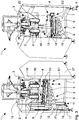
Figure 1 is a front view of the packaging machine of the invention arranged for packaging a first type of bag and with a second welding unit arranged in a first operative position; -
Figure 2 is a front view of the packaging machine ofFigure 1 with the second welding unit arranged in a second operative position; -
Figure 3 is a perspective front view of the machine ofFigure 1 ; -
Figure 4 is a perspective front view of the machine ofFigure 2 ; -
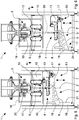
Figure 5 is a front view of the packaging machine of the invention arranged for packaging a second type of bag and with the second welding unit arranged in the first operative position; -
Figure 6 is a front view of the machine ofFigure 5 with the second welding unit arranged in the second operative position; -
Figure 7 is a perspective front view of the machine ofFigure 6 ; -
Figure 8 to 11 are perspective views of bags that can be produced by the packaging machine of the invention; -
Figure 12 is a side view which schematically illustrates foldings and welds carried out on a plastic film to produce a first type of bag in the packaging machine ofFigure 1 ; -
Figure 13 is a side view which schematically illustrates foldings and welds carried out on the plastic film to produce a second type of bag in the packaging machine ofFigure 5 ; -
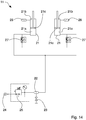
Figure 14 is a scheme of the balancing means of the packaging machine ofFigure 1 . - Referring to
Figures 1 to 7 , apackaging machine 1 according to the invention is illustrated, arranged to package inbags packaging machine 1 is able to produce bags or sacks by properly folding, welding and cutting a film orpellicle 50 made of plastic material, single or multi layer, introducing predetermined doses of products into said bags. - The
packaging machine 1 comprises a formingtube 2 around which theplastic film 50 is wrapped, that is unwound from areel 51, and a feeding unit, of the known type and not shown in the Figures, in order to dispense into the formingtube 2 defined doses of product to be packaged in the bags. - The forming
tube 2 is substantially arranged vertically beneath the feeding unit, which comprises a product hopper or reservoir and a valve adapted to release predetermined doses of products into the formingtube 2, on a cyclic basis coordinated with the functioning of the machine. The formingtube 2 has a shape (cross section) corresponding to the one of the bag to be produced.Figures 1 to 4 show for exemplary purposes a formingtube 2 having substantially quadrangular section and arranged to form a bag orsack 101 of the so called "square bottom" type with a single side weld (Figure 8 ) or a "square bottom" bag or sack 102 with four side welds (Figure 9 ). - The
machine 1 comprises afirst welding unit 3 for carrying out on thefilm 50 at least alongitudinal weld 52 parallel to a feed direction A of thefilm 50 along the formingtube 2 and asecond welding unit 4 for carrying out on thefilm 50transverse welds 54 in particular almost orthogonal to the feed direction A. - The
first welding unit 3 is arranged along the formingtube 2, below the feeding unit of the product and thesecond welding unit 4 is arranged downstream the formingtube 2 and thefirst welding unit 3 along the feed direction A. - The
second welding unit 4 is mounted rotatably about a rotation axis Z, substantially parallel to the feed direction A, so as to rotate and selectively carry outtransverse welds - The rotation of the
second welding unit 4 may be performed manually by an operator or automatically through proper motor means controlled by a management and control unit of the machine, of the known type and not described in detail. - The
second welding unit 4 comprises a couple ofwelding jaws 14 that are mutually opposite and movable between a closed position D1, in which they are in abutment against thefilm 50 in order to carry out thereon atransverse weld welding jaws 14 are spaced apart and disengaged from thefilm 50. Thewelding jaws 14 are movable on a welding plane W that is almost orthogonal to the rotation axis Z and substantially horizontal. - The
welding jaws 14 are driven by driving means 13 with reciprocating linear motion and coordinated with the feed motion of thefilm 50 along the feed direction A. - Cutting means is associated to the
second welding unit 4 for cutting transversally thefilm 50 at the transverse welds so as to separate from thefilm 50 the bags which are closed and containing respective doses of product. - The cutting means comprises, for example, a blade or knife housed in one of the
welding jaws 14 and a counter-blade housed in the remainingwelding jaw 14. - The
packaging machine 1 further comprises moving means 5 to support and move thesecond welding unit 4 along the feed direction A, in parallel to the rotation axis Z, with a reciprocating rectilinear motion so that the aforesaidsecond welding unit 4 can carry out thetransverse welds film 50 is moved with a continuous motion. - As it will be better described in the hereinafter description, the
packaging machine 1 of the invention may in fact function by moving thefilm 50 with continuous motion or with intermittent motion, according to the characteristics of thefilm 50 and/or of the bags to be produced and filled in with the product. - Hence, the
second welding unit 4 is driven by moving means 5 in its working stroke from a first operative position E1, wherein it is nearer to the formingtube 2 to receive the foldedfilm 50 in output from the latter, to a second operative position E2, wherein saidsecond welding unit 4 is more spaced apart from the formingtube 2. - Moving means 5 comprises a
carriage 6 supporting thesecond welding unit 4 and slidingly connected to a supportingframe 7 of themachine 1, and actuating means 10 to move theaforesaid carriage 6 along the feed direction A. The actuating means 10 comprises in particular, electric actuators of the linear type comprising for example a linear electric motor acting directly on thecarriage 6 or a rotatable electric motor connected to thecarriage 6 through motion transmission means adapted to transform the rotating motion of the electric motor into reciprocating linear motion and comprising, for example, a screw-nutscrew unit, a rod-crank kinematic motion or similar. - Moving means 5 further includes balancing or compensation means 11 arranged to cooperate with the actuating means 10 to move the
carriage 6. More precisely, balancing means 11 comprises one or more, for example two,cylinders 21 of the pneumatic or hydraulic type, connected to areservoir 22 of pressurised fluid (air, oil) and arranged to assist the actuating means 10, in particular in the upward movement of thecarriage 6, in a returning stroke of the latter from the second operative position E2 to the first operative position E1. - In the embodiment shown in the Figures, the balancing means 11 is of the pneumatic type and comprises a couple of
pneumatic cylinders 21 which are in flowing connection with areservoir 22 of pressurised air, fixed to the supportingframe 7 and connected with and acting on thecarriage 6. - As illustrated by the scheme of
Figure 14 showing a pneumatic circuit of the balancing means 11, thereservoir 22 of pressurised air is provided with avalve 23 adapted to make an established air-flow flow away from saidreservoir 22 into an outer environment in a substantially constant and continuous way during the functioning of themachine 1. Thereservoir 22 is also connected to and supplied by asource 24 of pressurized air to restore the air leaking out through thevalve 23. More precisely, apressure regulator 25 is interposed between thereservoir 22 and thesource 24 of pressurised air to regulate the inlet of pressurised air in saidreservoir 22, for example to allow the input of pressurised air coming from thesource 24 in thereservoir 22 when the air pressure in the latter reaches a prefixed value (minimum value). Thereby, a continuous exchange of pressurised air occurs inside thereservoir 22 allowing to maintain the temperature of the air controlled and substantially constant during the operation of thepackaging machine 1. The continuous exchange of the air allows also to check the air pressure too inside thereservoir 22. - The two
pneumatic cylinders 21 are of the single effect type and each comprises arespective piston 21c forming inside the cylinder body afirst chamber 21a connected and supplied by thereservoir 22 and asecond chamber 21b in communication with the outer environment, for example through asilencer 26. Aflow regulator 27 is connected to thefirst chamber 21a to check an output air speed from the latter, in particular the speed the air is sent with from thecylinders 21 into thereservoir 22. - The supporting
frame 7 of themachine 1 comprises afront wall 15 to which amiddle structure 16 supporting the formingtube 2, the feeding unit of the product and thefirst welding unit 3 and a pair ofside walls 17 are fixed, at least one of which is provided with slidingguides 18 to which thecarriage 6 of the movingmeans 5 is slidably connected. Thecarriage 6 comprises a pair of supportingarms 19 each other parallel and sliding and cantilever mounted on the respective sliding guides 18. - Each
cylinder 21 body is fixed to theside wall 17 provided with slidingguides 18, while the free end of a stem of therelative piston 21c is fixed to thecarriage 6, in particular to a respective supportingarm 19. - Actuating means 10 is fixed as well to the
side wall 17 provided with guides and are connected with and acting on thecarriage 6. - A
plate 8 is mounted on thecarriage 6 rotatably about the rotation axis Z to support thesecond welding unit 4. More precisely, theplate 8 is rotatably mounted on the supportingarms 19 and supports the couple ofwelding jaws 14 and the relative driving means 13. - The
first welding unit 3 is removable and interchangeable with one or more further first welding units able to carry out respective and different types of longitudinal welds on thefilm 50. To this end, thefirst welding unit 3 forms a module reversibly connected with the supportingframe 7, in particular with themiddle structure 16 thereof. - In the embodiment shown in
Figures 1 to 4 , wherein thepackaging machine 1 of the invention is arranged to function in continuous mode, thefirst welding unit 3 comprisesfirst welding elements 23 and asecond welding element 43 which enable to carry out longitudinal welds continuously on thefilm 50. More precisely, thefirst welding elements 23 are arranged to carry out continuously the fourlongitudinal welds 52 of the squarebottom bags 102 with four side welds, while thesecond welding element 43 is arranged to carry out the singlelongitudinal weld 52 of the squarebottom bags 101 with side weld. - In alternative, as shown in
Figures 5 to 7 , thefirst welding unit 3 may comprisethird welding elements 33 arranged to carry out continuously thelongitudinal weld 53 of Doypack® type bags 104. - The
first welding unit 3 may also be equipped with welding elements able to carry out longitudinal welds when thefilm 50 is moved with an intermittent motion. - Similarly, the forming
tube 2 is removable and interchangeable with one or more further forming tubes of different size and shapes in order to produce different types of bags or bags of different sizes. - The
packaging machine 1 is also provided with trailing means 9 to engage and move thefilm 50 wrapped around the formingtube 2 along the feed direction A. The trailing means 9 is fixed to thefront wall 15 of the supportingframe 7, interposed along the feed direction A between thefirst welding unit 3 and thesecond welding unit 4. The trailing means 9 is movable between an inactive position wherein it is disengaged from thefilm 50 and an active position wherein it is engaged with thefilm 50. The trailing means 9 comprises for example a pair of straps or pulling belts, motorized with closed loop, arranged to receive and drag thefilm 50 towards thesecond welding unit 4. - The
packaging machine 1 of the invention is configured to function by moving thefilm 50 with continuous or intermittent motion, according to the specific production needs (quality of the welds, size and shape of the bags) and/or to the plastic material to be folded and welded (high density and/or high thickness multilayer film). - In
Figures 1 to 4 and12 , thepackaging machine 1 of the invention is shown configured to function in continuous mode to package squarebottom bags 102 with four side welds (Figure 9 ), obtained by folding thefilm 50 around the formingtube 2 having quadrangular cross section and carrying out fourlongitudinal welds 52 on thefilm 50 and twotransverse welds 54, as schematically illustrated inFigure 12 , showing the folding process of thefilm 50 for this type of bag. - To this end, while functioning, the
film 50, unwound from therespective reel 51, is wrapped around the formingtube 2. Thefirst welding unit 3 is able to carry out continuously thelongitudinal welds 52 on thefilm 50 by means of thefirst welding elements 23, while thewelding jaws 14 of thesecond welding unit 4 carry out the transverse welds 54. More precisely, thewelding jaws 14 carry out a transverse weld which is cut or dissected by cutting means associated to thejaws 14 thereof. Thereby, a first transverse weld which closes at the top thebag 102 filled with product (dispensed through the formingtube 2 right before the closure of thewelding jaws 14 on the film 50) and a second transverse weld which closes the bag at the bottom arranged upstream thesecond welding unit 4 are carried out. - Thanks to the moving means 5, the
second welding unit 4 can be moved with reciprocating linear motion along the feed direction A so as to perform a working stroke in which it carries out thetransverse weld 54 on the advancingfilm 50 and a returning stroke in which thesecond welding unit 4 is taken into the first initial operative position E1 in which it starts interacting with thefilm 50. - The actuating means 10 connected with and controlled by the management and control unit of the
packaging machine 1 allows to regulate and set in a precise and at the same time simple and quick way, the extent of the working stroke and the profile of the linear speed which thecarriage 6 of the moving means 5 moves with during the working stroke and the returning stroke. - The aforesaid operative parameters (extent of the stroke, speed, acceleration) are selected and set according to the type of package to be produced, in other words according to the film plastic material, to the type and/or size of the bag.
- It must be noted that in this operative configuration of the
packaging machine 1, thesecond welding unit 4 is oriented around the rotation axis Z in such a way that thewelding jaws 14 carry out atransverse weld 54 arranged along a first welding direction B parallel to the welding plane W and to thefront wall 15 of the supportingframe 7. Thewelding jaws 14 are thus linearly movable in mutual approach or removal along a direction substantially orthogonal to the rotation axis Z and to thefront wall 15. - Thanks to the balancing means 11 which cooperates with the actuating means 10 to move the
carriage 6 upwards, during the returning stroke of the latter from the second operative position E2 to the first operative position E1, size and/or power of the actuating means 10 may be restrained as it is restrained the push they must exert on thecarriage 6. More precisely, during the returningstroke 6, the pressurised air coming from thereservoir 22 into thefirst chambers 21a of thecylinders 21 determines the extension of the respective pistons of the latter that is a push upwards exerted on thecarriage 6 which sums up to the push exerted by the actuating means 10. - On the contrary, during the working stroke from the first operative position E1 to the second operative position E2, the
pneumatic cylinders 21 substantially brake and slow down the downward motion of thecarriage 6, the pressurised air being pushed by thepistons 21c in the backward movement inside thereservoir 22 serving as compensating pneumatic cushion. Thereby, the balancing means 11 substantially balances the weight of thesecond welding unit 4 and of thecarriage 6, while the actuating means 10 regulates and controls the extent of the working stroke and the profile of the linear speed with which thecarriage 6 must move in the working and returning strokes. - It must also be noted that the balancing means 11 of the
packaging machine 1 of the invention allows to keep the temperature and the air pressure controlled inside thereservoir 22 thereby avoiding both the heating of the whole packaging machine 1 (the heat spreading from thereservoir 22 and from the cylinders) and its functioning at high pressure which might compromise the regular functioning of the balancing means 11 as well as their duration and reliability over time. Containing the temperature and the pressure of the air inside thereservoir 22 allows to limit, for example, the thermal and dynamic stress affecting the gaskets of thereservoir 22 and of the whole pneumatic circuit of the balancing means 11. - While the packaging machine is in function, the air in the
reservoir 22 is in fact affected by continuous compressions/decompressions caused by the movements of thepistons 21c of thecylinders 21 connected to thecarriage 6, that moves with a reciprocating movement. The compressions/decompressions of the air inside thereservoir 22 determine a gradual heating of the air thereof. However, thanks to thevalve 23 which allows the outlet of a determined air flow from thereservoir 22, and thanks to thepressure regulator 25 which allows the inlet of pressurised air coming from thesource 24 in thereservoir 22, when the temperature in the latter reaches a predetermined value (minimum value), it is possible to have a continuous exchange of air inside thereservoir 22 that allows to keep the temperature controlled and substantially constant during the functioning of thepackaging machine 1. By avoiding the heating of the air, an increase of the air pressure is at the same time avoided in thereservoir 22. - By using the
second welding element 43, arranged before the formingelement 2 and between the railing means 9, it is also possible to produce squarebottom bags 102 with side weld, having a singlelongitudinal weld 52 and onetransverse weld 54 with the same orientation of thesecond welding unit 4. - By mounting on the packaging machine 1 a proper forming tube and using the
second welding unit 43, it is also possible to producepillow bags 103 having onelongitudinal weld 52 and twotransverse welds 54 with the same orientation of thesecond welding unit 4. - The replacement of the forming
tube 2 and/or of thefirst welding unit 3 is quick and simple and it takes a very reduced stopping time of the machine. -
Figure 5 to 7 and13 show thepackaging machine 1 of the invention configured to function in continuous motion to package Doypack ® bags 104 (Figure 11 ). TheseDoypack ® bags 104 are obtained by folding thefilm 50 around a formingtube 12 substantially having oval elongated cross section and carrying out on thefilm 50 one endlongitudinal weld 53 and twotransverse welds 55, as schematically illustrated inFigure 13 which shows the folding process of thefilm 50 for this kind of bag. - While the machine is in function, the
film 50, unwound from thereel 51, is wrapped around the formingtube 12. Thefirst welding unit 3 is provided withthird welding elements 33 able to carry out continuously thelongitudinal weld 53 on thefilm 50, while thewelding jaws 14 of thesecond welding unit 4 carry out thetransverse welds 55 and at the same time they cut thefilm 50 to separate from the latter thebag 104 filled with product and closed. - In this case as well the moving means 5, with the actuating means 10 assisted by the balancing means 11, allows to move the
second welding unit 4 with reciprocating linear motion, along the feed direction A, parallel to the rotation axis Z, so as to perform a working stroke, in which thetransverse weld 55 is carried out on the advancingfilm 50 and a returning stroke wherein saidsecond welding unit 4 is moved from the lower second operative position E2 to the higher first operative position E1, in which thewelding jaws 14 start interacting with the film. - In this operative configuration of the
packaging machine 1, thesecond welding unit 4 is oriented around the rotation axis Z so that thewelding jaws 14 carry out atransverse weld 55 arranged along a second welding direction C parallel to the welding plane W and substantially orthogonal to thefront wall 15 of the supportingframe 7. Weldingjaws 14 are thus linearly movable in mutual approach or removal along a direction substantially orthogonal to the rotation axis Z and parallel to thefront wall 15. - The
packaging machine 1 of the invention is thus able to carry out all the different types of bags or sacks made from aplastic film 50 thanks to thesecond welding unit 4 rotatably about the rotation axis Z, parallel to the feed direction A. It is in fact possible , by rotating thesecond welding unit 4, to carry out on thefilm 50, in a quick and simple way, transverse welds along the two welding directions B, C orthogonal to each other and to the rotation axis Z (vertical). - Furthermore, thanks to the moving means 5, it is possible to move the
second welding unit 6 with reciprocating rectilinear motion, so that thewelding jaws 14 can carry out thetransverse welds film 50 is moved through a continuous motion. Thereby, thepackaging machine 1 of the invention is able to reach high production speed, while maintaining adequate precision and quality. - In alternative, moving means 5 can maintain the
second welding unit 5 stationary in a determined position while functioning with an intermittent motion of thepackaging machine 1. - Such a functioning option may be used to carry out precise and top quality welds and/or carry out packages using peculiar materials, such as high density and/or high thickness multilayer plastic films.
- The
packaging machine 1 of the invention is thus particularly flexible and versatile in the production. - Such flexibility is also due to the possibility to replace, in a quick and easy way, the
first welding unit 3 and the formingtube middle structure 16 of the supportingframe 7.
Claims (15)
- Packaging machine (1) for packaging products in bags (101; 102; 103; 104), in particular loose products of small size or powder or granular products, comprising- a forming tube (2; 12) around which a film (50) made of plastic material is wrapped that is unwound from a reel (51),- a feeding unit for dispensing into said forming tube (2; 12) defined doses of product to be packaged in said bags (101; 102; 103; 104);- a first welding unit (3) for carrying out on said film (50) at least a longitudinal weld (52; 53) parallel to a feed direction (A) of said film (50) along said forming tube (2; 12);- a second welding unit (4) for carrying out on said film (50) transverse welds (54; 55), in particular almost orthogonal to said feed direction (A), mounted rotatably about a rotation axis (Z), in particular substantially parallel to said feed direction (A), so as to carry out transverse welds (54; 55) at least along two welding directions (B, C) that are orthogonal to each other and to said feed direction (A); and- moving means (5) for supporting and moving said second welding unit (4) along said feed direction (A) with a reciprocating rectilinear motion, in particular said second welding unit (4) carrying out said transversal welds (54; 55) in a working stroke while said film (50) is moved with a continuous motion, said moving means (5) comprising a carriage (6), supporting said second welding unit (4) and slidingly connected to a supporting frame (7) of said machine (1), and actuating means (10) to move said carriage (6);said packaging machine (1) being characterized in that said moving means (5) further comprises balancing means (11) arranged to cooperate with said actuating means (10) for moving said carriage (6) and comprising one or more cylinders (21) in flowing connection with a reservoir (22) of pressurised air, fixed to said supporting frame (7) and connected with and acting on said carriage (6).
- Packaging machine (1) according to claim 1, wherein said first welding unit (3) is arranged below said feeding unit and along said forming tube (2; 12) and said second welding unit (4) is arranged downstream said forming tube (2; 12) and said first welding unit (3) along said feed direction (A).
- Packaging machine (1) according to claim 1 or 2, wherein said second welding unit (4) comprises a couple of welding jaws (14) that are mutually opposite and movable between a closed position (D1), in which they are in abutment against said film (50) in order to carry out thereon a transversal weld (54; 55), and an open position (D2), in which said welding jaws (14) are spaced apart and disengaged from said film (50).
- Packaging machine (1) according to claim 3, wherein said welding jaws (14) are movable on a welding plane (W) that is almost orthogonal to said rotation axis (Z).
- Packaging machine (1) according to any preceding claim, wherein said actuating means (10) comprises electric actuating means of the linear type, comprising in particular a linear electric motor acting directly on said carriage (6) or a rotatable electric motor connected to said carriage (6) through motion transmission means adapted to transform the rotating motion of said electric motor into reciprocating linear motion.
- Packaging machine (1) according to any preceding claim, wherein said balancing means (11) comprises a couple of pneumatic cylinders (21) fixed to said supporting frame (7) and connected with and acting on said carriage (6), said pneumatic cylinders (21) being in flowing connection with a reservoir (22) of pressurized air.
- Packaging machine (1) according to claim 6, wherein said reservoir (22) of pressurised air is provided with a valve (23) adapted to make an established air-flow flow away from the reservoir (22) into an outer environment, said reservoir (22) being connected to and supplied by a source (24) of pressurised air to restore the air leaking out through said valve (23), in particular to maintain a temperature of the air in said reservoir (22) substantially constant.
- Packaging machine (1) according to claim 7, wherein said balancing means (11) comprises a pressure regulator (25) interposed between said reservoir (22) and said source (24) of pressurized air to regulate the inlet of pressurized air into said reservoir (22).
- Packaging machine (1) according to any preceding claim, wherein said supporting frame (7) comprises a front wall (15) to which said feeding unit, said forming tube (2; 12) and said first welding unit (3) are fixed, and at least one side wall (17) provided with sliding guides (18) to which said carriage (6) is slidably connected.
- Packaging machine (1) according to claim 9, wherein said actuating means (10) and said at least one cylinder (21) are fixed to said side wall (17) provided with sliding guides (18).
- Packaging machine (1) according to any preceding claim, wherein said moving means (5) comprises a plate (8) that is mounted on said carriage (6) rotatably about said rotation axis (Z) to support said second welding unit (4).
- Packaging machine (1) according to claim 3 or 4, wherein said second welding unit (4) comprises driving means (13) for moving said welding jaws (14) with reciprocating linear motion that is coordinated with a feed motion of said film (50).
- Packaging machine (1) according to any preceding claim, wherein said first welding unit (3) is removable and interchangeable with one or more further first welding units able to carry out respective and different types of longitudinal welds on said film (50).
- Packaging machine (1) according to any preceding claim, comprising trailing means (9) to engage and move said film (50) wrapped on said forming tube (2; 12) along said feed direction (A), in particular said trailing means (9) being movable between an inactive position wherein it is disengaged from said film (50) and an active position wherein it is engaged with said film (50)
- Packaging machine (1) according to any preceding claim, comprising cutting means associated to said second welding unit (4) for cutting transversely said film (50) at said transverse welds (54; 55) so as to separate from said film (50) the bags (101; 104) which are closed and containing respective doses of product.
Applications Claiming Priority (1)
| Application Number | Priority Date | Filing Date | Title |
|---|---|---|---|
| ITUA2016A002990A ITUA20162990A1 (en) | 2016-04-28 | 2016-04-28 | VERTICAL PACKAGING MACHINE |
Publications (2)
| Publication Number | Publication Date |
|---|---|
| EP3239060A1 true EP3239060A1 (en) | 2017-11-01 |
| EP3239060B1 EP3239060B1 (en) | 2019-01-30 |
Family
ID=56801691
Family Applications (1)
| Application Number | Title | Priority Date | Filing Date |
|---|---|---|---|
| EP17168445.9A Active EP3239060B1 (en) | 2016-04-28 | 2017-04-27 | Vertical packaging machine |
Country Status (3)
| Country | Link |
|---|---|
| EP (1) | EP3239060B1 (en) |
| ES (1) | ES2721791T3 (en) |
| IT (1) | ITUA20162990A1 (en) |
Cited By (4)
| Publication number | Priority date | Publication date | Assignee | Title |
|---|---|---|---|---|
| CN110385856A (en) * | 2019-01-28 | 2019-10-29 | 东莞市华鑫通达自动化装备有限公司 | Expandable polyethylene package box processing machine |
| CN111463321A (en) * | 2020-04-13 | 2020-07-28 | 芜湖盘云石磨新能源科技有限公司 | Welding head for light-reflecting film-pasting photovoltaic module |
| CN114801195A (en) * | 2022-05-11 | 2022-07-29 | 福建恩迈特新材料有限公司 | Device and method for continuously attaching upper and lower cloth layers to height setting layer of inflatable product |
| WO2023078972A1 (en) * | 2021-11-05 | 2023-05-11 | Syntegon Packaging Solutions B.V. | Vertical form fill sealing machine and method for operating the vertical form fill sealing machine |
Families Citing this family (1)
| Publication number | Priority date | Publication date | Assignee | Title |
|---|---|---|---|---|
| CN110450400B (en) * | 2019-07-29 | 2021-07-02 | 江西凯美达铝业有限公司 | Protective film laminating device for rectangular aluminum profile |
Citations (7)
| Publication number | Priority date | Publication date | Assignee | Title |
|---|---|---|---|---|
| US3332206A (en) * | 1964-04-20 | 1967-07-25 | Clemson Ind Inc | Packaging apparatus |
| US4598533A (en) * | 1983-09-16 | 1986-07-08 | Kabushiki Kaisha Sanwa Jidoki Seisakusho | Lateral sealer device for vertical packaging machine |
| US20020020153A1 (en) * | 2000-06-30 | 2002-02-21 | O-Mega Packaging Ag | Supporting structure of a bag packaging machine |
| US20030217531A1 (en) * | 2002-05-24 | 2003-11-27 | Keen Bruce W. | Vertical form, fill, and seal apparatus for making several types of packages |
| US20040154271A1 (en) * | 2003-01-06 | 2004-08-12 | Rietjens Peter Wilhelmus Henricus | Device and method for manufacturing reclosable packagings |
| US20110005172A1 (en) * | 2009-01-15 | 2011-01-13 | Ohki Co., Ltd. | Packing-packaging apparatus |
| US20110192117A1 (en) * | 2010-02-10 | 2011-08-11 | Lubezny Vadim A | Seal and cut method and apparatus |
-
2016
- 2016-04-28 IT ITUA2016A002990A patent/ITUA20162990A1/en unknown
-
2017
- 2017-04-27 ES ES17168445T patent/ES2721791T3/en active Active
- 2017-04-27 EP EP17168445.9A patent/EP3239060B1/en active Active
Patent Citations (7)
| Publication number | Priority date | Publication date | Assignee | Title |
|---|---|---|---|---|
| US3332206A (en) * | 1964-04-20 | 1967-07-25 | Clemson Ind Inc | Packaging apparatus |
| US4598533A (en) * | 1983-09-16 | 1986-07-08 | Kabushiki Kaisha Sanwa Jidoki Seisakusho | Lateral sealer device for vertical packaging machine |
| US20020020153A1 (en) * | 2000-06-30 | 2002-02-21 | O-Mega Packaging Ag | Supporting structure of a bag packaging machine |
| US20030217531A1 (en) * | 2002-05-24 | 2003-11-27 | Keen Bruce W. | Vertical form, fill, and seal apparatus for making several types of packages |
| US20040154271A1 (en) * | 2003-01-06 | 2004-08-12 | Rietjens Peter Wilhelmus Henricus | Device and method for manufacturing reclosable packagings |
| US20110005172A1 (en) * | 2009-01-15 | 2011-01-13 | Ohki Co., Ltd. | Packing-packaging apparatus |
| US20110192117A1 (en) * | 2010-02-10 | 2011-08-11 | Lubezny Vadim A | Seal and cut method and apparatus |
Cited By (5)
| Publication number | Priority date | Publication date | Assignee | Title |
|---|---|---|---|---|
| CN110385856A (en) * | 2019-01-28 | 2019-10-29 | 东莞市华鑫通达自动化装备有限公司 | Expandable polyethylene package box processing machine |
| CN111463321A (en) * | 2020-04-13 | 2020-07-28 | 芜湖盘云石磨新能源科技有限公司 | Welding head for light-reflecting film-pasting photovoltaic module |
| CN111463321B (en) * | 2020-04-13 | 2021-09-24 | 上海绿兆新能源科技有限公司 | Welding head for light-reflecting film-pasting photovoltaic module |
| WO2023078972A1 (en) * | 2021-11-05 | 2023-05-11 | Syntegon Packaging Solutions B.V. | Vertical form fill sealing machine and method for operating the vertical form fill sealing machine |
| CN114801195A (en) * | 2022-05-11 | 2022-07-29 | 福建恩迈特新材料有限公司 | Device and method for continuously attaching upper and lower cloth layers to height setting layer of inflatable product |
Also Published As
| Publication number | Publication date |
|---|---|
| EP3239060B1 (en) | 2019-01-30 |
| ITUA20162990A1 (en) | 2017-10-28 |
| ES2721791T3 (en) | 2019-08-05 |
Similar Documents
| Publication | Publication Date | Title |
|---|---|---|
| EP3239060A1 (en) | Vertical packaging machine | |
| US11577906B2 (en) | Bundled product and system | |
| US10507942B2 (en) | Form-fill-seal machine and bag-making packaging machine | |
| EP3378793B1 (en) | Bag-making and packaging machine | |
| EP3353060B1 (en) | Process and machine for making clipless chub package contaning viscous product | |
| JPH02152610A (en) | Method and device for forming, filling and closing hose bag pack | |
| AU2017382763B2 (en) | Flexible jaws for vertical fill form and seal apparatus and methods of use | |
| WO2015190011A1 (en) | Multi-column automatic packaging machine | |
| US4448010A (en) | Method and apparatus for making bag-type packages | |
| US5852920A (en) | Longitudinal seam sealer for continuous motion form, fill and seal machine | |
| US20200353698A1 (en) | Bag-making and packaging machine | |
| JP6719402B2 (en) | Deaerator and packaging machine | |
| RU197016U1 (en) | VERTICAL PACKAGING MACHINE | |
| RU2471690C1 (en) | Multipacking machine | |
| RU2631695C1 (en) | Method of packaging viscous product into three-shear seals from thermoplastic polymer film and packaging and film machine of vertical execution, implementing the method | |
| JP5941651B2 (en) | Horizontal bag making and packaging machine and its end seal control device | |
| JP2012206726A (en) | Gusset former for horizontal bag making-filling-packaging machine | |
| JPS63281934A (en) | Lateral seal apparatus of packing machine | |
| EP0267904A1 (en) | Film handling apparatus for positive displacement filling machine | |
| WO2006056840A2 (en) | Apparatuses and methods for packaging a product |
Legal Events
| Date | Code | Title | Description |
|---|---|---|---|
| PUAI | Public reference made under article 153(3) epc to a published international application that has entered the european phase |
Free format text: ORIGINAL CODE: 0009012 |
|
| STAA | Information on the status of an ep patent application or granted ep patent |
Free format text: STATUS: THE APPLICATION HAS BEEN PUBLISHED |
|
| AK | Designated contracting states |
Kind code of ref document: A1 Designated state(s): AL AT BE BG CH CY CZ DE DK EE ES FI FR GB GR HR HU IE IS IT LI LT LU LV MC MK MT NL NO PL PT RO RS SE SI SK SM TR |
|
| AX | Request for extension of the european patent |
Extension state: BA ME |
|
| STAA | Information on the status of an ep patent application or granted ep patent |
Free format text: STATUS: REQUEST FOR EXAMINATION WAS MADE |
|
| 17P | Request for examination filed |
Effective date: 20180430 |
|
| RBV | Designated contracting states (corrected) |
Designated state(s): AL AT BE BG CH CY CZ DE DK EE ES FI FR GB GR HR HU IE IS IT LI LT LU LV MC MK MT NL NO PL PT RO RS SE SI SK SM TR |
|
| GRAP | Despatch of communication of intention to grant a patent |
Free format text: ORIGINAL CODE: EPIDOSNIGR1 |
|
| STAA | Information on the status of an ep patent application or granted ep patent |
Free format text: STATUS: GRANT OF PATENT IS INTENDED |
|
| RIC1 | Information provided on ipc code assigned before grant |
Ipc: B65B 9/22 20060101ALI20180718BHEP Ipc: B29C 65/78 20060101ALI20180718BHEP Ipc: B65B 51/30 20060101ALI20180718BHEP Ipc: B65B 9/207 20120101ALI20180718BHEP Ipc: B29C 65/00 20060101ALI20180718BHEP Ipc: B29C 65/74 20060101ALI20180718BHEP Ipc: B65B 9/213 20120101ALI20180718BHEP Ipc: B65B 59/04 20060101ALI20180718BHEP Ipc: B65B 51/14 20060101ALI20180718BHEP Ipc: B29C 65/02 20060101ALI20180718BHEP Ipc: B65B 9/20 20120101AFI20180718BHEP |
|
| INTG | Intention to grant announced |
Effective date: 20180814 |
|
| GRAS | Grant fee paid |
Free format text: ORIGINAL CODE: EPIDOSNIGR3 |
|
| GRAA | (expected) grant |
Free format text: ORIGINAL CODE: 0009210 |
|
| STAA | Information on the status of an ep patent application or granted ep patent |
Free format text: STATUS: THE PATENT HAS BEEN GRANTED |
|
| AK | Designated contracting states |
Kind code of ref document: B1 Designated state(s): AL AT BE BG CH CY CZ DE DK EE ES FI FR GB GR HR HU IE IS IT LI LT LU LV MC MK MT NL NO PL PT RO RS SE SI SK SM TR |
|
| REG | Reference to a national code |
Ref country code: GB Ref legal event code: FG4D |
|
| REG | Reference to a national code |
Ref country code: CH Ref legal event code: EP |
|
| REG | Reference to a national code |
Ref country code: AT Ref legal event code: REF Ref document number: 1093060 Country of ref document: AT Kind code of ref document: T Effective date: 20190215 |
|
| REG | Reference to a national code |
Ref country code: IE Ref legal event code: FG4D |
|
| REG | Reference to a national code |
Ref country code: DE Ref legal event code: R096 Ref document number: 602017001974 Country of ref document: DE |
|
| REG | Reference to a national code |
Ref country code: LT Ref legal event code: MG4D |
|
| REG | Reference to a national code |
Ref country code: NL Ref legal event code: MP Effective date: 20190130 |
|
| PG25 | Lapsed in a contracting state [announced via postgrant information from national office to epo] |
Ref country code: NO Free format text: LAPSE BECAUSE OF FAILURE TO SUBMIT A TRANSLATION OF THE DESCRIPTION OR TO PAY THE FEE WITHIN THE PRESCRIBED TIME-LIMIT Effective date: 20190430 Ref country code: PT Free format text: LAPSE BECAUSE OF FAILURE TO SUBMIT A TRANSLATION OF THE DESCRIPTION OR TO PAY THE FEE WITHIN THE PRESCRIBED TIME-LIMIT Effective date: 20190530 Ref country code: SE Free format text: LAPSE BECAUSE OF FAILURE TO SUBMIT A TRANSLATION OF THE DESCRIPTION OR TO PAY THE FEE WITHIN THE PRESCRIBED TIME-LIMIT Effective date: 20190130 Ref country code: PL Free format text: LAPSE BECAUSE OF FAILURE TO SUBMIT A TRANSLATION OF THE DESCRIPTION OR TO PAY THE FEE WITHIN THE PRESCRIBED TIME-LIMIT Effective date: 20190130 Ref country code: NL Free format text: LAPSE BECAUSE OF FAILURE TO SUBMIT A TRANSLATION OF THE DESCRIPTION OR TO PAY THE FEE WITHIN THE PRESCRIBED TIME-LIMIT Effective date: 20190130 Ref country code: LT Free format text: LAPSE BECAUSE OF FAILURE TO SUBMIT A TRANSLATION OF THE DESCRIPTION OR TO PAY THE FEE WITHIN THE PRESCRIBED TIME-LIMIT Effective date: 20190130 Ref country code: FI Free format text: LAPSE BECAUSE OF FAILURE TO SUBMIT A TRANSLATION OF THE DESCRIPTION OR TO PAY THE FEE WITHIN THE PRESCRIBED TIME-LIMIT Effective date: 20190130 |
|
| REG | Reference to a national code |
Ref country code: ES Ref legal event code: FG2A Ref document number: 2721791 Country of ref document: ES Kind code of ref document: T3 Effective date: 20190805 |
|
| REG | Reference to a national code |
Ref country code: AT Ref legal event code: MK05 Ref document number: 1093060 Country of ref document: AT Kind code of ref document: T Effective date: 20190130 |
|
| PG25 | Lapsed in a contracting state [announced via postgrant information from national office to epo] |
Ref country code: HR Free format text: LAPSE BECAUSE OF FAILURE TO SUBMIT A TRANSLATION OF THE DESCRIPTION OR TO PAY THE FEE WITHIN THE PRESCRIBED TIME-LIMIT Effective date: 20190130 Ref country code: RS Free format text: LAPSE BECAUSE OF FAILURE TO SUBMIT A TRANSLATION OF THE DESCRIPTION OR TO PAY THE FEE WITHIN THE PRESCRIBED TIME-LIMIT Effective date: 20190130 Ref country code: BG Free format text: LAPSE BECAUSE OF FAILURE TO SUBMIT A TRANSLATION OF THE DESCRIPTION OR TO PAY THE FEE WITHIN THE PRESCRIBED TIME-LIMIT Effective date: 20190430 Ref country code: LV Free format text: LAPSE BECAUSE OF FAILURE TO SUBMIT A TRANSLATION OF THE DESCRIPTION OR TO PAY THE FEE WITHIN THE PRESCRIBED TIME-LIMIT Effective date: 20190130 Ref country code: GR Free format text: LAPSE BECAUSE OF FAILURE TO SUBMIT A TRANSLATION OF THE DESCRIPTION OR TO PAY THE FEE WITHIN THE PRESCRIBED TIME-LIMIT Effective date: 20190501 Ref country code: IS Free format text: LAPSE BECAUSE OF FAILURE TO SUBMIT A TRANSLATION OF THE DESCRIPTION OR TO PAY THE FEE WITHIN THE PRESCRIBED TIME-LIMIT Effective date: 20190530 |
|
| PG25 | Lapsed in a contracting state [announced via postgrant information from national office to epo] |
Ref country code: SK Free format text: LAPSE BECAUSE OF FAILURE TO SUBMIT A TRANSLATION OF THE DESCRIPTION OR TO PAY THE FEE WITHIN THE PRESCRIBED TIME-LIMIT Effective date: 20190130 Ref country code: EE Free format text: LAPSE BECAUSE OF FAILURE TO SUBMIT A TRANSLATION OF THE DESCRIPTION OR TO PAY THE FEE WITHIN THE PRESCRIBED TIME-LIMIT Effective date: 20190130 Ref country code: DK Free format text: LAPSE BECAUSE OF FAILURE TO SUBMIT A TRANSLATION OF THE DESCRIPTION OR TO PAY THE FEE WITHIN THE PRESCRIBED TIME-LIMIT Effective date: 20190130 Ref country code: AL Free format text: LAPSE BECAUSE OF FAILURE TO SUBMIT A TRANSLATION OF THE DESCRIPTION OR TO PAY THE FEE WITHIN THE PRESCRIBED TIME-LIMIT Effective date: 20190130 Ref country code: RO Free format text: LAPSE BECAUSE OF FAILURE TO SUBMIT A TRANSLATION OF THE DESCRIPTION OR TO PAY THE FEE WITHIN THE PRESCRIBED TIME-LIMIT Effective date: 20190130 |
|
| REG | Reference to a national code |
Ref country code: DE Ref legal event code: R097 Ref document number: 602017001974 Country of ref document: DE |
|
| PG25 | Lapsed in a contracting state [announced via postgrant information from national office to epo] |
Ref country code: SM Free format text: LAPSE BECAUSE OF FAILURE TO SUBMIT A TRANSLATION OF THE DESCRIPTION OR TO PAY THE FEE WITHIN THE PRESCRIBED TIME-LIMIT Effective date: 20190130 |
|
| PLBE | No opposition filed within time limit |
Free format text: ORIGINAL CODE: 0009261 |
|
| STAA | Information on the status of an ep patent application or granted ep patent |
Free format text: STATUS: NO OPPOSITION FILED WITHIN TIME LIMIT |
|
| REG | Reference to a national code |
Ref country code: BE Ref legal event code: MM Effective date: 20190430 |
|
| PG25 | Lapsed in a contracting state [announced via postgrant information from national office to epo] |
Ref country code: AT Free format text: LAPSE BECAUSE OF FAILURE TO SUBMIT A TRANSLATION OF THE DESCRIPTION OR TO PAY THE FEE WITHIN THE PRESCRIBED TIME-LIMIT Effective date: 20190130 Ref country code: MC Free format text: LAPSE BECAUSE OF FAILURE TO SUBMIT A TRANSLATION OF THE DESCRIPTION OR TO PAY THE FEE WITHIN THE PRESCRIBED TIME-LIMIT Effective date: 20190130 Ref country code: LU Free format text: LAPSE BECAUSE OF NON-PAYMENT OF DUE FEES Effective date: 20190427 |
|
| 26N | No opposition filed |
Effective date: 20191031 |
|
| PG25 | Lapsed in a contracting state [announced via postgrant information from national office to epo] |
Ref country code: BE Free format text: LAPSE BECAUSE OF NON-PAYMENT OF DUE FEES Effective date: 20190430 Ref country code: SI Free format text: LAPSE BECAUSE OF FAILURE TO SUBMIT A TRANSLATION OF THE DESCRIPTION OR TO PAY THE FEE WITHIN THE PRESCRIBED TIME-LIMIT Effective date: 20190130 |
|
| PG25 | Lapsed in a contracting state [announced via postgrant information from national office to epo] |
Ref country code: TR Free format text: LAPSE BECAUSE OF FAILURE TO SUBMIT A TRANSLATION OF THE DESCRIPTION OR TO PAY THE FEE WITHIN THE PRESCRIBED TIME-LIMIT Effective date: 20190130 |
|
| PG25 | Lapsed in a contracting state [announced via postgrant information from national office to epo] |
Ref country code: IE Free format text: LAPSE BECAUSE OF NON-PAYMENT OF DUE FEES Effective date: 20190427 |
|
| REG | Reference to a national code |
Ref country code: CH Ref legal event code: PL |
|
| PG25 | Lapsed in a contracting state [announced via postgrant information from national office to epo] |
Ref country code: LI Free format text: LAPSE BECAUSE OF NON-PAYMENT OF DUE FEES Effective date: 20200430 Ref country code: CH Free format text: LAPSE BECAUSE OF NON-PAYMENT OF DUE FEES Effective date: 20200430 |
|
| PG25 | Lapsed in a contracting state [announced via postgrant information from national office to epo] |
Ref country code: CY Free format text: LAPSE BECAUSE OF FAILURE TO SUBMIT A TRANSLATION OF THE DESCRIPTION OR TO PAY THE FEE WITHIN THE PRESCRIBED TIME-LIMIT Effective date: 20190130 |
|
| PG25 | Lapsed in a contracting state [announced via postgrant information from national office to epo] |
Ref country code: HU Free format text: LAPSE BECAUSE OF FAILURE TO SUBMIT A TRANSLATION OF THE DESCRIPTION OR TO PAY THE FEE WITHIN THE PRESCRIBED TIME-LIMIT; INVALID AB INITIO Effective date: 20170427 Ref country code: MT Free format text: LAPSE BECAUSE OF FAILURE TO SUBMIT A TRANSLATION OF THE DESCRIPTION OR TO PAY THE FEE WITHIN THE PRESCRIBED TIME-LIMIT Effective date: 20190130 |
|
| PG25 | Lapsed in a contracting state [announced via postgrant information from national office to epo] |
Ref country code: MK Free format text: LAPSE BECAUSE OF FAILURE TO SUBMIT A TRANSLATION OF THE DESCRIPTION OR TO PAY THE FEE WITHIN THE PRESCRIBED TIME-LIMIT Effective date: 20190130 |
|
| PGFP | Annual fee paid to national office [announced via postgrant information from national office to epo] |
Ref country code: CZ Payment date: 20230322 Year of fee payment: 7 |
|
| P01 | Opt-out of the competence of the unified patent court (upc) registered |
Effective date: 20230515 |
|
| PGFP | Annual fee paid to national office [announced via postgrant information from national office to epo] |
Ref country code: IT Payment date: 20230426 Year of fee payment: 7 Ref country code: FR Payment date: 20230425 Year of fee payment: 7 Ref country code: ES Payment date: 20230503 Year of fee payment: 7 Ref country code: DE Payment date: 20230426 Year of fee payment: 7 |
|
| PGFP | Annual fee paid to national office [announced via postgrant information from national office to epo] |
Ref country code: GB Payment date: 20230420 Year of fee payment: 7 |