EP3239016B1 - System for pushing or retaining a train on steep slopes - Google Patents
System for pushing or retaining a train on steep slopes Download PDFInfo
- Publication number
- EP3239016B1 EP3239016B1 EP17000645.6A EP17000645A EP3239016B1 EP 3239016 B1 EP3239016 B1 EP 3239016B1 EP 17000645 A EP17000645 A EP 17000645A EP 3239016 B1 EP3239016 B1 EP 3239016B1
- Authority
- EP
- European Patent Office
- Prior art keywords
- retain
- push
- railway line
- railway
- train
- Prior art date
- Legal status (The legal status is an assumption and is not a legal conclusion. Google has not performed a legal analysis and makes no representation as to the accuracy of the status listed.)
- Active
Links
- 239000000203 mixture Substances 0.000 claims description 38
- 230000003137 locomotive effect Effects 0.000 claims description 14
- 230000009194 climbing Effects 0.000 claims description 3
- 238000000034 method Methods 0.000 claims description 3
- 230000007704 transition Effects 0.000 claims description 3
- 238000006243 chemical reaction Methods 0.000 claims description 2
- 238000005096 rolling process Methods 0.000 claims description 2
- 229910000831 Steel Inorganic materials 0.000 description 7
- 239000010959 steel Substances 0.000 description 7
- 230000032258 transport Effects 0.000 description 4
- 230000001174 ascending effect Effects 0.000 description 1
- 230000015572 biosynthetic process Effects 0.000 description 1
- 230000008878 coupling Effects 0.000 description 1
- 238000010168 coupling process Methods 0.000 description 1
- 238000005859 coupling reaction Methods 0.000 description 1
- 230000005484 gravity Effects 0.000 description 1
- 239000011435 rock Substances 0.000 description 1
Images
Classifications
-
- B—PERFORMING OPERATIONS; TRANSPORTING
- B61—RAILWAYS
- B61J—SHIFTING OR SHUNTING OF RAIL VEHICLES
- B61J3/00—Shunting or short-distance haulage devices; Similar devices for hauling trains on steep gradients or as starting aids; Car propelling devices therefor
- B61J3/04—Car shunting or haulage devices with cable traction or endless-chain driving means
- B61J3/06—Car shunting or haulage devices with cable traction or endless-chain driving means with vehicle-engaging truck or carriage
Definitions
- the object of the invention is a system and a method for pushing or retaining a train on the steep slopes of a railway line by using a haulage cable and a push/retain assist vehicle. It is a known fact that the adhesion forces of locomotives prevent train compositions from overcoming steep slopes. This is why railways have long lines that make it possible to overcome substantial differences in altitude. Slopes, i.e. inclinations, on conventional railway lines reach up to 25 ⁇ , most commonly up to 17 %o. Today, rack railways are used for slopes up to 140 %o for passenger railway connections, while freight traffic does not go beyond 79 ⁇ . It is understandable that steeper slopes require a more powerful pulling force and this is normally achieved by including two locomotives.
- the wagons with or without locomotive is coupled to the assist vehicle by specially designed holding devices (22, 23) and after pulling the train and overcoming the steep slope, the train is decoupled from the assist vehicle.
- the system is using a pulling system with one axis which is not suitable for train compositions of huge masses since the weight of the assist vehicle should be equal to the weight of the locomotive.
- the task of the invention is a system for pushing or retaining a train that will allow a simple, rapid and reliable driving of a heavy train on a railway line with a steep slope, where differences in height of 300 to 500 m are to be overcome and the length of the railway line will not have to be extended in a spiral loop or by other shapes of curvature.
- the task is solved by a system according to claim 1.
- the system allows a continuous drive of a train and the related drive of an assist vehicle by coupling the assist vehicle at the rear side, whereby in the upper section the assist vehicle is automatically disconnected and the train composition drives on without stopping or braking the train composition.
- a mechanical and electronic system 6 supervises and controls the ascending and descending of the train composition 5.
- the push/retain assist vehicle 3 is fastened to the steel cable 4 in the upper position and starts accelerating in front of the train composition 5 while descending in a way that the locomotive of the descending train composition 5 reduces the speed and that the essential part of the necessary braking energy is taken over by the push/retain assist vehicle 3 which then takes over all the braking energy during descending and translates it to the force of the steel cables 4 which are connected through huge drive wheels with the engine-generator of the system 6 in such a way as to allow conversion of the mechanical energy to electrical energy.
- the push/retain assist vehicle 3 in the lower section then moves away from the locomotive of the train composition 5 by increasing the speed in order to reach the railway switch 1 considerably earlier and to move away from the line of the railway tracks, thus making it possible for the special railway switch 1, after the push/retain assist vehicle 3 has passed it, to assume a position, i.e. to switch the railway switch 1 into a position in which the train composition 5 can drive through the railway switch to a normal railway line and to ensure free access for a new train composition for hill climbing.
- the system of the invention consists of a low-slope railway line with a train composition 5 and of a short railway line parallel thereto with a push/retain assist vehicle 3, both lines being connected by a railway switch 1.
- the joined line starts from the railway switch 1 along the length of the train composition 5 with a low slope and then passes to a steep slope.
- the route line of the push/retain assist vehicle 3 is a straight line 2 without any turns throughout the entire length.
- the push/retain assist vehicle 3 is fastened to the pull cable 4 between the rails of the railway line 2.
- the railway line passes from a steep slope to the line of a low slope; an engine-generator of the system 6 is arranged at this transition and has a bullwheel for the pulling cable 4.
- the system for pushing or retaining a train consists of known devices and elements that are used in railroad traffic. By using all the accompanying devices and elements, the system provides for an uninterrupted drive of a train composition from takeover at the entry point at the lower section to discharge the train formation to a conventional railway network at the upper section.
Landscapes
- Engineering & Computer Science (AREA)
- Mechanical Engineering (AREA)
- Electric Propulsion And Braking For Vehicles (AREA)
- Train Traffic Observation, Control, And Security (AREA)
Description
- The object of the invention is a system and a method for pushing or retaining a train on the steep slopes of a railway line by using a haulage cable and a push/retain assist vehicle.
It is a known fact that the adhesion forces of locomotives prevent train compositions from overcoming steep slopes. This is why railways have long lines that make it possible to overcome substantial differences in altitude. Slopes, i.e. inclinations, on conventional railway lines reach up to 25 ‰, most commonly up to 17 %o. Today, rack railways are used for slopes up to 140 %o for passenger railway connections, while freight traffic does not go beyond 79 ‰. It is understandable that steeper slopes require a more powerful pulling force and this is normally achieved by including two locomotives. The need for a pulling force is considerably increased on steep slopes and this is why slopes not exceeding 17 ‰ are normally used for the railway lines of passenger trains. In the case of steep slopes locomotives having a larger pulling force are used, for instance, a locomotive having a pulling force of 800 k N, which is used for slopes up to 40 ‰.
For surmounting steeper slopes a rack railway may be used. It exceeds the force for overcoming resistances and gravity by a huge rack, usually with parallel teeth in order to better overcome the load by postponing the splitting.
There are also known solutions for pulling train compositions using a steel cable for transports up to 8 km. Such solutions are frequently used in cities or local transport at an airport.
Known solutions for reducing the length of railway lines and consequently increasing the slopes are carried out by using additional locomotives or by an extra increase in friction, which is achieved by spreading rocks or steel shavings or by pushing or retaining with additional pull assist vehicles that transfer the force through a toothed profile. - All the prior used systems are limited to low-weight transport, especially to passenger trains. Yet none of the known systems has been used for the huge masses of train compositions and slopes that exceed the slopes known in conventional railway lines by more than three times.
The best-known solution of pulling and retaining with a steel cable is used in San Francisco, where the use of a steel cable is justified due to steep slopes of up to 200 %o. The loads are relatively small since the weight of the assist vehicles and the passengers is relatively small.
InDE patent No. 3244017 a system for pulling a train over a steep slope with the assist vehicle is disclosed, wherein the train, i.e. the wagons with or without locomotive, is coupled to the assist vehicle by specially designed holding devices (22, 23) and after pulling the train and overcoming the steep slope, the train is decoupled from the assist vehicle. The system is using a pulling system with one axis which is not suitable for train compositions of huge masses since the weight of the assist vehicle should be equal to the weight of the locomotive.
The task of the invention is a system for pushing or retaining a train that will allow a simple, rapid and reliable driving of a heavy train on a railway line with a steep slope, where differences in height of 300 to 500 m are to be overcome and the length of the railway line will not have to be extended in a spiral loop or by other shapes of curvature. - According to the invention, the task is solved by a system according to claim 1. The system allows a continuous drive of a train and the related drive of an assist vehicle by coupling the assist vehicle at the rear side, whereby in the upper section the assist vehicle is automatically disconnected and the train composition drives on without stopping or braking the train composition. The invention will be described by way of drawings, in which:
-
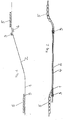
Figure 1 : shows the cross-section of a system according to the invention with the assist vehicle, -
Figure 2 : shows an elevation of the system according to the invention with the assist vehicle. - A mechanical and electronic system 6 supervises and controls the ascending and descending of the
train composition 5. The push/retain assist vehicle 3 is fastened to thesteel cable 4 in the upper position and starts accelerating in front of thetrain composition 5 while descending in a way that the locomotive of the descendingtrain composition 5 reduces the speed and that the essential part of the necessary braking energy is taken over by the push/retain assist vehicle 3 which then takes over all the braking energy during descending and translates it to the force of thesteel cables 4 which are connected through huge drive wheels with the engine-generator of the system 6 in such a way as to allow conversion of the mechanical energy to electrical energy. The push/retain assist vehicle 3 in the lower section then moves away from the locomotive of thetrain composition 5 by increasing the speed in order to reach the railway switch 1 considerably earlier and to move away from the line of the railway tracks, thus making it possible for the special railway switch 1, after the push/retain assist vehicle 3 has passed it, to assume a position, i.e. to switch the railway switch 1 into a position in which thetrain composition 5 can drive through the railway switch to a normal railway line and to ensure free access for a new train composition for hill climbing. - The system of the invention consists of a low-slope railway line with a
train composition 5 and of a short railway line parallel thereto with a push/retain assist vehicle 3, both lines being connected by a railway switch 1. The joined line starts from the railway switch 1 along the length of thetrain composition 5 with a low slope and then passes to a steep slope. The route line of the push/retain assist vehicle 3 is astraight line 2 without any turns throughout the entire length. The push/retain assist vehicle 3 is fastened to thepull cable 4 between the rails of therailway line 2. On the upper section, the railway line passes from a steep slope to the line of a low slope; an engine-generator of the system 6 is arranged at this transition and has a bullwheel for thepulling cable 4. - The system for pushing or retaining a train consists of known devices and elements that are used in railroad traffic. By using all the accompanying devices and elements, the system provides for an uninterrupted drive of a train composition from takeover at the entry point at the lower section to discharge the train formation to a conventional railway network at the upper section.
Claims (3)
- A system for pushing or retaining a train on steep slopes of a railway line, the system comprising a haulage cable and an assist-vehicle, characterized in that the system is formed of a railway line of a low slope, i.e. with an inclination up to 25 ‰, for a train composition (5) and of a railway line for a push/retain assist vehicle (3), wherein said railway line is parallel to the railway line of the low slope, both said railway lines are connected by a railway switch (1) and form one strait joined railway line; the joined railway line starts from the railway switch (1) with a low slope, and then passes to a steep slope, i.e. with an inclination that exceeds the slopes known in conventional railway lines by more than three times, on its upper section, said joined railway line passes at a transition from the steep slope to a joined railway line of a low slope, wherein the route of the push/retain assist vehicle (3) is a straight railway line (2) throughout its entire length; the push/retain assist vehicle (3) is fastened to a pull cable (4); the system further comprising an engine-generator (6) that is arranged at the transition and has a bullwheel for the pulling cable (4), and regulators.
- A method for a system according to claim 1 for pushing or retaining a train on steep slopes of a railway line by using a haulage cable and an assist-vehicle, characterized in that, after the train composition (5) with its last wagon in hill climbing has completely passed the railroad switch (1) and reached the straight joined railway line, a push/retain assist vehicle (3) moving with a speed corresponding to a speed of the train composition (5) comes via the railroad switch (1) in contact with the last wagon of the train composition (5), and then the push/retain assist vehicle (3) starts pushing with all the force ensured by the cable (4) transferred to the push/retain assist vehicle (3) by direct contact of the push/retain assist vehicle (3) with the last wagon of the train composition (5), such that the pulling force of the locomotive of the train composition (5) is exploited to the maximum and together with the pulling force of the push/retain assist vehicle (3) provides the necessary force to overcome the rolling resistance and all other resistances and the slope component of the weight of the entire train composition (5) until reaching the upper section of the joined railway line, and when reaching the upper section of the joined railway line, the train composition (5) starts accelerating, while the push/retain assist vehicle (3) stops, wherein when the train composition (5) is descending the push/retain assist vehicle (3) starts accelerating in front of the train composition (5) to come in contact with the locomotive thus the essential part of the necessary braking energy is taken over by the push/retain assist vehicle (3) which translates said braking energy during descending to the force of the pull cables (4) which are connected through bullwheel with the engine-generator (6) of the system in such a way as to enable conversion of the mechanical energy to electrical energy.
- A method for a system according to claim 1 for pushing or retaining a train on steep slopes of a railway line by using a haulage cable and a push/retain assist vehicle, characterized in that when the train composition (5) is descending on the joined railway line of the steep slope, the push/retain assist vehicle (3) in the lower section of the joined railway line moves away from the train composition (5) by increasing the speed with regard to the speed of the train composition (5) in order to reach the railway switch (1) earlier and to move away from the joined railway line, thus making it possible for the railway switch (1), after the push/retain assist vehicle (3) has passed it, to switch into position in which the train composition can drive through the railway switch (1) to the railway line and to ensure free access for a new train composition for hill climbing.
Applications Claiming Priority (1)
| Application Number | Priority Date | Filing Date | Title |
|---|---|---|---|
| SI201600120A SI25167A (en) | 2016-04-26 | 2016-04-26 | A system for pushing or pulling the train at major inclines |
Publications (2)
| Publication Number | Publication Date |
|---|---|
| EP3239016A1 EP3239016A1 (en) | 2017-11-01 |
| EP3239016B1 true EP3239016B1 (en) | 2019-02-20 |
Family
ID=59014416
Family Applications (1)
| Application Number | Title | Priority Date | Filing Date |
|---|---|---|---|
| EP17000645.6A Active EP3239016B1 (en) | 2016-04-26 | 2017-04-14 | System for pushing or retaining a train on steep slopes |
Country Status (2)
| Country | Link |
|---|---|
| EP (1) | EP3239016B1 (en) |
| SI (1) | SI25167A (en) |
Families Citing this family (3)
| Publication number | Priority date | Publication date | Assignee | Title |
|---|---|---|---|---|
| CN110562273B (en) * | 2019-10-09 | 2024-07-12 | 中建空列(北京)科技有限公司 | Abrupt slope driving auxiliary system |
| CN111775977B (en) * | 2020-07-10 | 2021-10-01 | 北京天润海图科技有限公司 | Boosting damping system of rail car and rail car operation control method |
| CN113417693B (en) * | 2021-07-13 | 2023-06-13 | 晋能控股煤业集团同忻煤矿山西有限公司 | Safety migration method for mining fully-mechanized mining equipment under steep slope |
Family Cites Families (4)
| Publication number | Priority date | Publication date | Assignee | Title |
|---|---|---|---|---|
| DE467048C (en) * | 1928-10-18 | Schenck Und Liebe Harkort Akt | Large inclined elevator by means of friction winch | |
| US1125110A (en) * | 1914-07-11 | 1915-01-19 | Mcmyler Interstate Company | Car-haulage system. |
| DE3244017C2 (en) * | 1982-11-27 | 1986-04-10 | M.A.N. Maschinenfabrik Augsburg-Nürnberg AG, 4200 Oberhausen | Transport system for rail-bound wagons on inclined routes |
| CN2505356Y (en) * | 2001-09-24 | 2002-08-14 | 马钢(集团)控股有限公司 | Hillside railway transportation train set |
-
2016
- 2016-04-26 SI SI201600120A patent/SI25167A/en active IP Right Grant
-
2017
- 2017-04-14 EP EP17000645.6A patent/EP3239016B1/en active Active
Non-Patent Citations (1)
| Title |
|---|
| None * |
Also Published As
| Publication number | Publication date |
|---|---|
| EP3239016A1 (en) | 2017-11-01 |
| SI25167A (en) | 2017-10-30 |
Similar Documents
| Publication | Publication Date | Title |
|---|---|---|
| CN100482507C (en) | Guideway and chassis system for wheel based rail running vehicle | |
| US7992501B2 (en) | Transportation system | |
| EP3747722B1 (en) | Hybrid cable/rail transportation system | |
| CN101772437B (en) | Power supply installation for a railway vehicle | |
| EP3239016A1 (en) | System for pushing or retaining a train on steep slopes | |
| EP2957478A1 (en) | System and method for passengers to board on and exit from a train without the train stopping at a train station | |
| CN102574529B (en) | An urban commuter / material carrying facility with non linear aerial ropeway | |
| RU2477694C2 (en) | Railway car mule (versions) and railway car mule platform | |
| CN208429073U (en) | A kind of rack drives system | |
| CN106218646A (en) | The movement station chassis that the method detrained in not parking movement and method use | |
| CN114269665A (en) | Hybrid cable/rail transportation system | |
| CN201143942Y (en) | Vehicle body for railway track laying bridge erection machine | |
| CN206606208U (en) | Riding rail vehicle | |
| RU2664091C1 (en) | Air train and its travel tracks | |
| CN102114843A (en) | Method for loading and unloading passengers and transferring passengers and realizing equipment thereof | |
| US10118629B2 (en) | High speed transportation system | |
| CN102765398A (en) | Side-hung train boarding and alighting system | |
| CN112793592A (en) | Suspension type conveyer | |
| US1794089A (en) | Suspension-rail track system | |
| CN205168539U (en) | System of dropping off guests on not stopping fast | |
| CN106627593A (en) | Transportation facility enabling train to achieve energy consumption and pass through ramp road section without decelerating | |
| CN202022206U (en) | Side-hung type train boarding system | |
| Wynne | Operation on the Norfolk & Western railway | |
| RU2501684C2 (en) | Method and device for high-speed operation of passenger train on single-track railway | |
| DE102008034424A1 (en) | Rail-bound car routing method for railroad shunting yard, involves connecting locking device when exceeding maximum wind velocity, disconnecting device when falling below maximum wind velocity and inducing rolling back of car by ambient air |
Legal Events
| Date | Code | Title | Description |
|---|---|---|---|
| PUAI | Public reference made under article 153(3) epc to a published international application that has entered the european phase |
Free format text: ORIGINAL CODE: 0009012 |
|
| STAA | Information on the status of an ep patent application or granted ep patent |
Free format text: STATUS: THE APPLICATION HAS BEEN PUBLISHED |
|
| AK | Designated contracting states |
Kind code of ref document: A1 Designated state(s): AL AT BE BG CH CY CZ DE DK EE ES FI FR GB GR HR HU IE IS IT LI LT LU LV MC MK MT NL NO PL PT RO RS SE SI SK SM TR |
|
| AX | Request for extension of the european patent |
Extension state: BA ME |
|
| STAA | Information on the status of an ep patent application or granted ep patent |
Free format text: STATUS: REQUEST FOR EXAMINATION WAS MADE |
|
| 17P | Request for examination filed |
Effective date: 20180419 |
|
| RAX | Requested extension states of the european patent have changed |
Extension state: ME Payment date: 20180419 Extension state: BA |
|
| RBV | Designated contracting states (corrected) |
Designated state(s): AL AT BE BG CH CY CZ DE DK EE ES FI FR GB GR HR HU IE IS IT LI LT LU LV MC MK MT NL NO PL PT RO RS SE SI SK SM TR |
|
| GRAP | Despatch of communication of intention to grant a patent |
Free format text: ORIGINAL CODE: EPIDOSNIGR1 |
|
| STAA | Information on the status of an ep patent application or granted ep patent |
Free format text: STATUS: GRANT OF PATENT IS INTENDED |
|
| INTG | Intention to grant announced |
Effective date: 20181121 |
|
| GRAS | Grant fee paid |
Free format text: ORIGINAL CODE: EPIDOSNIGR3 |
|
| GRAA | (expected) grant |
Free format text: ORIGINAL CODE: 0009210 |
|
| STAA | Information on the status of an ep patent application or granted ep patent |
Free format text: STATUS: THE PATENT HAS BEEN GRANTED |
|
| AK | Designated contracting states |
Kind code of ref document: B1 Designated state(s): AL AT BE BG CH CY CZ DE DK EE ES FI FR GB GR HR HU IE IS IT LI LT LU LV MC MK MT NL NO PL PT RO RS SE SI SK SM TR |
|
| AX | Request for extension of the european patent |
Extension state: ME |
|
| REG | Reference to a national code |
Ref country code: GB Ref legal event code: FG4D |
|
| REG | Reference to a national code |
Ref country code: CH Ref legal event code: EP |
|
| REG | Reference to a national code |
Ref country code: AT Ref legal event code: REF Ref document number: 1097780 Country of ref document: AT Kind code of ref document: T Effective date: 20190315 |
|
| REG | Reference to a national code |
Ref country code: IE Ref legal event code: FG4D |
|
| REG | Reference to a national code |
Ref country code: DE Ref legal event code: R096 Ref document number: 602017002143 Country of ref document: DE |
|
| PGFP | Annual fee paid to national office [announced via postgrant information from national office to epo] |
Ref country code: LU Payment date: 20190411 Year of fee payment: 3 |
|
| REG | Reference to a national code |
Ref country code: LT Ref legal event code: MG4D Ref country code: NL Ref legal event code: MP Effective date: 20190220 |
|
| PG25 | Lapsed in a contracting state [announced via postgrant information from national office to epo] |
Ref country code: PT Free format text: LAPSE BECAUSE OF FAILURE TO SUBMIT A TRANSLATION OF THE DESCRIPTION OR TO PAY THE FEE WITHIN THE PRESCRIBED TIME-LIMIT Effective date: 20190620 Ref country code: ES Free format text: LAPSE BECAUSE OF FAILURE TO SUBMIT A TRANSLATION OF THE DESCRIPTION OR TO PAY THE FEE WITHIN THE PRESCRIBED TIME-LIMIT Effective date: 20190220 Ref country code: SE Free format text: LAPSE BECAUSE OF FAILURE TO SUBMIT A TRANSLATION OF THE DESCRIPTION OR TO PAY THE FEE WITHIN THE PRESCRIBED TIME-LIMIT Effective date: 20190220 Ref country code: NO Free format text: LAPSE BECAUSE OF FAILURE TO SUBMIT A TRANSLATION OF THE DESCRIPTION OR TO PAY THE FEE WITHIN THE PRESCRIBED TIME-LIMIT Effective date: 20190520 Ref country code: FI Free format text: LAPSE BECAUSE OF FAILURE TO SUBMIT A TRANSLATION OF THE DESCRIPTION OR TO PAY THE FEE WITHIN THE PRESCRIBED TIME-LIMIT Effective date: 20190220 Ref country code: LT Free format text: LAPSE BECAUSE OF FAILURE TO SUBMIT A TRANSLATION OF THE DESCRIPTION OR TO PAY THE FEE WITHIN THE PRESCRIBED TIME-LIMIT Effective date: 20190220 |
|
| PGFP | Annual fee paid to national office [announced via postgrant information from national office to epo] |
Ref country code: DE Payment date: 20190410 Year of fee payment: 3 Ref country code: IE Payment date: 20190410 Year of fee payment: 3 Ref country code: MC Payment date: 20190411 Year of fee payment: 3 |
|
| PG25 | Lapsed in a contracting state [announced via postgrant information from national office to epo] |
Ref country code: BG Free format text: LAPSE BECAUSE OF FAILURE TO SUBMIT A TRANSLATION OF THE DESCRIPTION OR TO PAY THE FEE WITHIN THE PRESCRIBED TIME-LIMIT Effective date: 20190520 Ref country code: NL Free format text: LAPSE BECAUSE OF FAILURE TO SUBMIT A TRANSLATION OF THE DESCRIPTION OR TO PAY THE FEE WITHIN THE PRESCRIBED TIME-LIMIT Effective date: 20190220 Ref country code: RS Free format text: LAPSE BECAUSE OF FAILURE TO SUBMIT A TRANSLATION OF THE DESCRIPTION OR TO PAY THE FEE WITHIN THE PRESCRIBED TIME-LIMIT Effective date: 20190220 Ref country code: HR Free format text: LAPSE BECAUSE OF FAILURE TO SUBMIT A TRANSLATION OF THE DESCRIPTION OR TO PAY THE FEE WITHIN THE PRESCRIBED TIME-LIMIT Effective date: 20190220 Ref country code: GR Free format text: LAPSE BECAUSE OF FAILURE TO SUBMIT A TRANSLATION OF THE DESCRIPTION OR TO PAY THE FEE WITHIN THE PRESCRIBED TIME-LIMIT Effective date: 20190521 Ref country code: IS Free format text: LAPSE BECAUSE OF FAILURE TO SUBMIT A TRANSLATION OF THE DESCRIPTION OR TO PAY THE FEE WITHIN THE PRESCRIBED TIME-LIMIT Effective date: 20190620 Ref country code: LV Free format text: LAPSE BECAUSE OF FAILURE TO SUBMIT A TRANSLATION OF THE DESCRIPTION OR TO PAY THE FEE WITHIN THE PRESCRIBED TIME-LIMIT Effective date: 20190220 |
|
| PGFP | Annual fee paid to national office [announced via postgrant information from national office to epo] |
Ref country code: FR Payment date: 20190423 Year of fee payment: 3 Ref country code: BE Payment date: 20190410 Year of fee payment: 3 |
|
| REG | Reference to a national code |
Ref country code: AT Ref legal event code: MK05 Ref document number: 1097780 Country of ref document: AT Kind code of ref document: T Effective date: 20190220 |
|
| PG25 | Lapsed in a contracting state [announced via postgrant information from national office to epo] |
Ref country code: CZ Free format text: LAPSE BECAUSE OF FAILURE TO SUBMIT A TRANSLATION OF THE DESCRIPTION OR TO PAY THE FEE WITHIN THE PRESCRIBED TIME-LIMIT Effective date: 20190220 Ref country code: IT Free format text: LAPSE BECAUSE OF FAILURE TO SUBMIT A TRANSLATION OF THE DESCRIPTION OR TO PAY THE FEE WITHIN THE PRESCRIBED TIME-LIMIT Effective date: 20190220 Ref country code: RO Free format text: LAPSE BECAUSE OF FAILURE TO SUBMIT A TRANSLATION OF THE DESCRIPTION OR TO PAY THE FEE WITHIN THE PRESCRIBED TIME-LIMIT Effective date: 20190220 Ref country code: SK Free format text: LAPSE BECAUSE OF FAILURE TO SUBMIT A TRANSLATION OF THE DESCRIPTION OR TO PAY THE FEE WITHIN THE PRESCRIBED TIME-LIMIT Effective date: 20190220 Ref country code: AL Free format text: LAPSE BECAUSE OF FAILURE TO SUBMIT A TRANSLATION OF THE DESCRIPTION OR TO PAY THE FEE WITHIN THE PRESCRIBED TIME-LIMIT Effective date: 20190220 Ref country code: DK Free format text: LAPSE BECAUSE OF FAILURE TO SUBMIT A TRANSLATION OF THE DESCRIPTION OR TO PAY THE FEE WITHIN THE PRESCRIBED TIME-LIMIT Effective date: 20190220 Ref country code: EE Free format text: LAPSE BECAUSE OF FAILURE TO SUBMIT A TRANSLATION OF THE DESCRIPTION OR TO PAY THE FEE WITHIN THE PRESCRIBED TIME-LIMIT Effective date: 20190220 |
|
| REG | Reference to a national code |
Ref country code: DE Ref legal event code: R097 Ref document number: 602017002143 Country of ref document: DE |
|
| PG25 | Lapsed in a contracting state [announced via postgrant information from national office to epo] |
Ref country code: SM Free format text: LAPSE BECAUSE OF FAILURE TO SUBMIT A TRANSLATION OF THE DESCRIPTION OR TO PAY THE FEE WITHIN THE PRESCRIBED TIME-LIMIT Effective date: 20190220 Ref country code: PL Free format text: LAPSE BECAUSE OF FAILURE TO SUBMIT A TRANSLATION OF THE DESCRIPTION OR TO PAY THE FEE WITHIN THE PRESCRIBED TIME-LIMIT Effective date: 20190220 |
|
| PLBE | No opposition filed within time limit |
Free format text: ORIGINAL CODE: 0009261 |
|
| STAA | Information on the status of an ep patent application or granted ep patent |
Free format text: STATUS: NO OPPOSITION FILED WITHIN TIME LIMIT |
|
| PG25 | Lapsed in a contracting state [announced via postgrant information from national office to epo] |
Ref country code: AT Free format text: LAPSE BECAUSE OF FAILURE TO SUBMIT A TRANSLATION OF THE DESCRIPTION OR TO PAY THE FEE WITHIN THE PRESCRIBED TIME-LIMIT Effective date: 20190220 |
|
| 26N | No opposition filed |
Effective date: 20191121 |
|
| PG25 | Lapsed in a contracting state [announced via postgrant information from national office to epo] |
Ref country code: SI Free format text: LAPSE BECAUSE OF FAILURE TO SUBMIT A TRANSLATION OF THE DESCRIPTION OR TO PAY THE FEE WITHIN THE PRESCRIBED TIME-LIMIT Effective date: 20190220 |
|
| PG25 | Lapsed in a contracting state [announced via postgrant information from national office to epo] |
Ref country code: TR Free format text: LAPSE BECAUSE OF FAILURE TO SUBMIT A TRANSLATION OF THE DESCRIPTION OR TO PAY THE FEE WITHIN THE PRESCRIBED TIME-LIMIT Effective date: 20190220 |
|
| REG | Reference to a national code |
Ref country code: DE Ref legal event code: R119 Ref document number: 602017002143 Country of ref document: DE |
|
| PG25 | Lapsed in a contracting state [announced via postgrant information from national office to epo] |
Ref country code: MC Free format text: LAPSE BECAUSE OF NON-PAYMENT OF DUE FEES Effective date: 20200430 |
|
| REG | Reference to a national code |
Ref country code: CH Ref legal event code: PL |
|
| PG25 | Lapsed in a contracting state [announced via postgrant information from national office to epo] |
Ref country code: CH Free format text: LAPSE BECAUSE OF NON-PAYMENT OF DUE FEES Effective date: 20200430 Ref country code: FR Free format text: LAPSE BECAUSE OF NON-PAYMENT OF DUE FEES Effective date: 20200430 Ref country code: LU Free format text: LAPSE BECAUSE OF NON-PAYMENT OF DUE FEES Effective date: 20200414 Ref country code: LI Free format text: LAPSE BECAUSE OF NON-PAYMENT OF DUE FEES Effective date: 20200430 Ref country code: DE Free format text: LAPSE BECAUSE OF NON-PAYMENT OF DUE FEES Effective date: 20201103 |
|
| REG | Reference to a national code |
Ref country code: BE Ref legal event code: MM Effective date: 20200430 |
|
| PG25 | Lapsed in a contracting state [announced via postgrant information from national office to epo] |
Ref country code: BE Free format text: LAPSE BECAUSE OF NON-PAYMENT OF DUE FEES Effective date: 20200430 |
|
| PG25 | Lapsed in a contracting state [announced via postgrant information from national office to epo] |
Ref country code: IE Free format text: LAPSE BECAUSE OF NON-PAYMENT OF DUE FEES Effective date: 20200414 |
|
| PG25 | Lapsed in a contracting state [announced via postgrant information from national office to epo] |
Ref country code: CY Free format text: LAPSE BECAUSE OF FAILURE TO SUBMIT A TRANSLATION OF THE DESCRIPTION OR TO PAY THE FEE WITHIN THE PRESCRIBED TIME-LIMIT Effective date: 20190220 |
|
| PG25 | Lapsed in a contracting state [announced via postgrant information from national office to epo] |
Ref country code: MT Free format text: LAPSE BECAUSE OF FAILURE TO SUBMIT A TRANSLATION OF THE DESCRIPTION OR TO PAY THE FEE WITHIN THE PRESCRIBED TIME-LIMIT Effective date: 20190220 Ref country code: HU Free format text: LAPSE BECAUSE OF FAILURE TO SUBMIT A TRANSLATION OF THE DESCRIPTION OR TO PAY THE FEE WITHIN THE PRESCRIBED TIME-LIMIT; INVALID AB INITIO Effective date: 20170414 |
|
| PGFP | Annual fee paid to national office [announced via postgrant information from national office to epo] |
Ref country code: GB Payment date: 20210412 Year of fee payment: 5 |
|
| PG25 | Lapsed in a contracting state [announced via postgrant information from national office to epo] |
Ref country code: MK Free format text: LAPSE BECAUSE OF FAILURE TO SUBMIT A TRANSLATION OF THE DESCRIPTION OR TO PAY THE FEE WITHIN THE PRESCRIBED TIME-LIMIT Effective date: 20190220 |
|
| GBPC | Gb: european patent ceased through non-payment of renewal fee |
Effective date: 20220414 |
|
| PG25 | Lapsed in a contracting state [announced via postgrant information from national office to epo] |
Ref country code: GB Free format text: LAPSE BECAUSE OF NON-PAYMENT OF DUE FEES Effective date: 20220414 |