EP3238976A1 - Regelsystem und verfahren zur regelung einer andruckkraft eines schleifstücks - Google Patents
Regelsystem und verfahren zur regelung einer andruckkraft eines schleifstücks Download PDFInfo
- Publication number
- EP3238976A1 EP3238976A1 EP17167451.8A EP17167451A EP3238976A1 EP 3238976 A1 EP3238976 A1 EP 3238976A1 EP 17167451 A EP17167451 A EP 17167451A EP 3238976 A1 EP3238976 A1 EP 3238976A1
- Authority
- EP
- European Patent Office
- Prior art keywords
- speed
- measuring device
- travel
- wind
- wind speed
- Prior art date
- Legal status (The legal status is an assumption and is not a legal conclusion. Google has not performed a legal analysis and makes no representation as to the accuracy of the status listed.)
- Granted
Links
Images

Classifications
-
- B—PERFORMING OPERATIONS; TRANSPORTING
- B60—VEHICLES IN GENERAL
- B60L—PROPULSION OF ELECTRICALLY-PROPELLED VEHICLES; SUPPLYING ELECTRIC POWER FOR AUXILIARY EQUIPMENT OF ELECTRICALLY-PROPELLED VEHICLES; ELECTRODYNAMIC BRAKE SYSTEMS FOR VEHICLES IN GENERAL; MAGNETIC SUSPENSION OR LEVITATION FOR VEHICLES; MONITORING OPERATING VARIABLES OF ELECTRICALLY-PROPELLED VEHICLES; ELECTRIC SAFETY DEVICES FOR ELECTRICALLY-PROPELLED VEHICLES
- B60L5/00—Current collectors for power supply lines of electrically-propelled vehicles
- B60L5/18—Current collectors for power supply lines of electrically-propelled vehicles using bow-type collectors in contact with trolley wire
- B60L5/22—Supporting means for the contact bow
- B60L5/28—Devices for lifting and resetting the collector
- B60L5/32—Devices for lifting and resetting the collector using fluid pressure
Definitions
- the invention relates to a control system and a method for controlling a pressing force of a contact piece of a pantograph of a rail vehicle, wherein the arranged thereon by means of a positioning of the pantograph grinding piece is applied with the pressing force against a catenary system, wherein by means of a travel measuring device of a measuring device of a control system of the rail vehicle a travel speed of the rail vehicle is determined, wherein by means of a control device of the control system, the pressing force is regulated in dependence on the driving speed.
- Such control systems and methods are well known and are used in rail vehicles with pantographs, in particular trains or the like.
- Current collectors are regularly arranged on a roof of a rail vehicle and comprise a movable positioning device, which can be designed as a rocker, a pantograph or a Einarmsystem.
- a movable positioning device which can be designed as a rocker, a pantograph or a Einarmsystem.
- At an upper end of the positioning device are one or more sliding pieces arranged, wherein the grinding pieces are formed substantially of graphite.
- the positioning device is moved by means of a pneumatic or electric drive, pneumatic drives predominantly being used in particular for trains.
- Above the pneumatic drive which can have one or more actuators, the contact piece is pressed against a contact line or a contact wire above the rail vehicle with a contact pressure force.
- a pressing force must be so great that the sliding piece is not disconnected from the catenary during travel of the rail vehicle or takes off, as this can lead to an undesirable sparkover between the catenary and contact piece, which in turn promotes rapid wear of the contact strip or a break can result. Therefore, the pressure force of the contact strip on the catenary is always controlled in response to a travel speed of the rail vehicle. Under the pressure force is here an orthogonal to the longitudinal extent of the catenary acting force that is exerted by the contact strip on the catenary understood.
- Rail vehicles also have a travel measuring device for measuring a travel speed of the rail vehicle. This travel speed is used to control the pressure force by means of a control device of a control system of the rail vehicle. If the rail vehicle has a pneumatic drive of the positioning device, by means of a so-called proportional pressure regulator, a pressure of an actuator on the positioning device, and thus a pressing force of the sliding piece on the catenary depending on the travel speed can be controlled so that the contact pressure is increased with increasing travel speed. Thus, it can be prevented that the contact strip dissolves undesirably even at high speeds of the catenary. At high speeds, speeds are understood> 100 km / h.
- a disadvantage of the known method is that with increasing travel speed of the rail vehicle, a wind at a travel speed corresponding to the wind speed acts on the pantograph or the sliding piece and presses the contact strip due to aerodynamic effects on the catenary. That is, as the vehicle speed increases, a pressing force is increased by a vehicle speed force component.
- the higher the pressure force of the contact strip on the catenary is formed the higher is also the abrasion of the formed of graphite contact piece and thus a wear of the same.
- a wear of the grinding piece is again significantly increased when a rail vehicle or train at high speed passes through a tunnel. Newer tunnels can be designed with a length of many kilometers and with a single tunnel tube for a track alone.
- the object of the invention is therefore to propose a method for controlling a pressing force of a contact strip and a control system for a pantograph, which prolongs a service life of a contact strip.
- a pressing force (F A ) of a contact strip of a current collector of a rail vehicle a sliding device of a measuring device of a control system of the rail vehicle, a travel speed (vF) of the rail vehicle is determined by means of a positioning device of the pantograph with the contact pressure (F A ) against a contact line, said means of a control device of the control system the pressure force (F A ) is controlled as a function of the travel speed (vF), wherein a real wind speed (vW R ) relative to the rail vehicle is determined by means of a wind measuring device of the measuring device, wherein by means of the control device, the pressing force (F A ) taking into account the real wind speed (vW R ) is regulated.
- the wind measuring device is used to measure the real wind speed (vW R ).
- the real wind speed (vW R ) results from the wind conditions which prevail at the location of the rail vehicle or directly at the pantograph independently of a traveling wind speed (vW F ). Since the pressure force (F A ) is already regulated by the control device as a function of the travel speed (vF), it becomes possible to correct the pressure force (F A ) by supplementing the measurement of the real wind speed (vW R ). For example, if a rail vehicle passes through a tunnel, the pressure force (F A ) would increase substantially in an undesired manner due to the aerodynamic effects.
- the pressing force (F A ) can always be controlled in proportion to the travel speed (vF).
- the control system may therefore include, for example, a known proportional pressure regulator, which regulates a pressure for a pneumatic actuator.
- the method for controlling a pressing force (F A ) can also be carried out by retrofitting proportional pressure regulators with the control device.
- the travel speed (vF) may correspond to a travel wind speed (vW F ), wherein the real wind speed (vW R ) may be determined as the difference between a total wind speed (vW ges ) and the travel speed (vF) or the airstream speed (vW F ).
- a measurement of the travel speed (vF) is carried out regularly on each rail vehicle, for example on a wheel of a rail vehicle, so that the control device can easily process this then known size.
- the travel wind speed (vW F ) can be measured once again separately by means of the wind measuring device.
- a real wind speed (vW R ) can then be determined particularly easily, for example by means of a Prandtl tube.
- a total speed (vW ges ) can be measured on the positioning device.
- a simple pitot tube can be used as the wind measuring device when the vehicle speed (vF) or the vehicle speed (vW F ) is already known.
- the wind measuring device is then particularly easy to train.
- the wind measuring device can also be arranged directly on the positioning device, in particular adjacent to the grinding piece, in order to determine the actual wind conditions or flow conditions on the grinding piece.
- the pressure force (F A ) is then more precisely regulated.
- a driving wind speed force component (F WFY ) may be determined depending on the running speed (vF) or a running wind speed (vW F ) and / or a real wind speed force component (F WRY ) depending on the real wind speed (vW R ) by means of the control device.
- the travel wind speed (vW F ) and the real wind speed (vW R ) act on the contact block in the opposite direction to the direction of movement of the contact piece relative to the contact line.
- the real wind speed (vW R ) can also be a component of a wind acting laterally on the rail vehicle.
- the pressing force (F A ) may be the sum of the negative real wind speed force component (F WRY ) and the travel speed force component (F AvK ), and the travel speed force component (F AvK ) may be controlled by the control device. Consequently, in the regulation of the pressing force (F A ) alone, the force component (F AvK ) provided for the respective speed of the rail vehicle and the real wind speed force component can be used (F WRY ). Theêtwind Anthony-force component (F WFY ) can then be neglected. Alone by this consideration of the real wind speed (vW R ), it is already possible to significantly reduce wear of the contact strip and to improve contact quality.
- a service life of the grinding piece can be further increased if the pressing force (F A ) is the sum of the traveling-wind speed force component (F WFY ), the real-speed negative force component (F WRY ) and the vehicle speed force component (F AvK ) the travel speed force component (F AvK ) can be controlled by the control device.
- the pressure force (F A ) can be adapted to all the pressure force influencing aerodynamic forces.
- the traveling wind speed force component (F WFY ) and the traveling speed force component (F AvK ) may be determined by considering the height of the grinding piece by means of the control device.
- a height of the grinding piece is in principle dependent on its wear, so that a new contact piece regularly is always higher than a long time in use befindliches contact strip, since here the height has already been reduced by abrasion.
- the height of the grinding piece also has an effect on the aerodynamic behavior of the grinding piece and thus, in particular, on the pressure force (F A ) influenced by wind speeds.
- the control device may now determine or compute the vehicle wind speed force component (F WFY ) and the vehicle speed force component (F AvK ) based on a known height of the slider . It can be provided to measure the height of the contact strip at regular intervals by means of a height measuring device in order to regulate the pressure force (F A ) even more precisely.
- a function of values of the real wind speed (vW R ) and values of the Real wind velocity force component (F WRY ) are stored.
- the control device may accordingly comprise means for data processing with the storage device.
- the function stored in the memory device then allows an association of the real wind speed (vW R ) determined by the wind measuring device to a value of the real wind speed force component (F WRY ).
- the regulation of the pressure force (F A ) is further simplified.
- a calibration of the function by a measurement of the pressing force (F A ) and a total wind speed (vW ges ) take place.
- the contact pressure (F A ) of the contact strip on the contact line can be determined, for example, by means of force sensors which are arranged on or in the vicinity of the contact strip.
- the actual pressure force as a function of the total wind speed (vW ges ) can be determined, in which case each of the function can be adjusted so that the control device always the desired pressure force (F A ), which is adapted to the travel speed (vF) adjusted.
- the calibration makes it possible to apply the method to any types and models of rail vehicles or pantographs, since then the respective different flow conditions can be taken into account on the rail vehicles.
- a height of the grinding piece can be measured continuously, wherein by means of the regulating device, the pressing force is controlled taking into account the height.
- the height measuring device can be, for example, a camera that detects the contact strip or a sensor that is installed on or within the contact strip. It is essential that the height of the contact strip during operation can be continuously measured, so that the pressure force (F A ) can always be adapted to the same by means of the control device to a constantly changing height by abrasion of the contact strip. In addition to the regulation of the pressure force (F A ) can then be initiated by means of the height measuring device also a lowering of the sliding piece when the grinding piece falls below a minimum height to prevent damage to the catenary.
- the pantograph on a movable positioning and at least one arranged thereon sliding piece, wherein by means of the positioning device, the sliding piece with a pressing force (F A ) against a catenary to the plant can be brought
- the control system is a measuring device and a control device, wherein the measuring device has a travel measuring device for determining a travel speed (vF) of a rail vehicle, wherein by means of the control device, the pressing force (F A ) is controllable in dependence on the vehicle speed (vF), wherein the measuring device is a wind measuring device for determining a real Wind speed (vW R ) relative to the rail vehicle, wherein by means of the control device, the pressing force (F A ), taking into account the real wind speed (vW R ) is adjustable.
- the wind measuring device may be a Venturi tube, a pitot tube, a Prandtl tube or an anemometer, in particular an ultrasonic anemometer, a thermoelectric anemometer, a thermo-optical anemometer, a plate anemometer.
- the wind measuring device for measuring the real wind velocity (VW R) or a total wind speed (VW ges) formed.
- the wind measuring device may be arranged on a roof of the rail vehicle in the vicinity of the current collector or directly on the positioning device adjacent to the contact strip.
- the wind gauge may include a fiber optic air velocity sensor.
- the fiber optic sensor can then form a thermo-optical anemometer. It is particularly advantageous that the fiber optic sensor can not be influenced by electromagnetic fields as they are present at pantographs regularly.
- the fiber-optic sensor can therefore also be arranged adjacent to the contact strip, without the result of the measurement being able to be distorted by currents flowing through the contact block or, for example, a flashover. Also, the sensor can not be disabled as a pitot tube due to contamination.
- the measuring device may comprise a height measuring device, by means of which a height of the grinding piece is measurable, wherein the height measuring device may comprise a fiber-optic sensor which may be disposed within the grinding piece.
- the fiber optic sensor for measuring the height of the contact strip is then also not influenced by electromagnetic fields.
- the height measuring device it is possible with the height measuring device to adjust the pressing force (F A ) to the actual height of the contact strip. If the fiber-optic sensor is arranged inside the contact strip, the fiber-optic sensor is also shielded from external influences that can falsify a measurement result.
- a unidirectional fiber bundle can be arranged in a vertical bore in the contact strip, wherein the fiber bundle can completely fill the bore.
- the fiber optic sensor is then formed by the fiber bundle in the bore.
- the bore may be a blind bore or a through bore in the slip piece.
- abrasion of the contact piece by contact with the contact line abrasion of the bundle of fibers also takes place, as a result of which a length of the bundle of fibers is shortened. This change in length of the fiber bundle can be detected, resulting in a height of the contact strip.
- a plurality of spaced-apart fiber bundles may be arranged in the grinding piece. The fact that the fiber bundle is only inserted into the vertical bore is the fiber optic sensor easy to assemble. It can also be provided as needed to fix or shed the fiber bundle in the bore by an adhesive material.
- the travel measuring device can be formed independently of the wind measuring device.
- the travel measuring device can then be the travel measuring device, which is in any case formed on a rail vehicle, for determining and displaying a driving speed, for example for a vehicle driver. It can then be dispensed with a supplementary training of a travel measuring device. Nevertheless, a wind speed (vW F ) can be measured by means of the wind measuring device in order to obtain an even more accurate measurement result.
- the wind measuring device may form the travel measuring device. Then, a travel speed (vF) is measured by the wind measuring device alone.
- the control system can then be designed independently of any existing already existing travel measuring device of a rail vehicle, whereby the control system is more universally applicable to rail vehicles.
- a wind measuring device When using a wind measuring device according to the invention, it is intended to use these for determining a real wind speed (vW R ) at a current collector of a rail vehicle. This makes it possible to use only the real wind speed (vW R ) for accurately controlling a pressing force (F A ) of a sliding piece of the current collector of the rail vehicle with the advantages described above.
- the Fig. 1 shows a pantograph 10 on a roof 11 of a rail vehicle not shown here with a trained as a pantograph 12 positioning device 13.
- a pantograph 12 positioning device 13 On the pantograph 12, two contact strips 14 are arranged on a rocker 15 transverse to a contact line 16.
- the rail vehicle moves at a travel speed vF relative to the catenary 16, the rail vehicle being flowed parallel to the catenary 16 at a total wind speed vW ges .
- the sliding pieces 14 are pressed transversely or orthogonally to the contact line 16 with a pressing force F A.
- the pressing force F A is controlled by means of a control device, not shown.
- the Fig. 2 shows a schematic representation of the contact strip 14 on the contact line 16 with vectors drawn on a vertical axis 17 of the contact strip 14 vectors.
- a total wind speed vW ges is composed of a travel wind speed vW F and a real wind speed vW R.
- the travel wind speed vW F is the same as a travel speed vF or counteracts this.
- the real wind speed vW R therefore corresponds to the proportion of a wind acting on the current collector or sliding piece 14, irrespective of the travel speed vF.
- This Wind can also be negative, ie act with the direction of travel of the rail vehicle and thus reduce the travel wind speed vW F and the total wind speed vW ges .
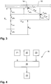
- the Fig. 3 shows the sliding piece 14 and the catenary 16 with a sliding piece 14 during a driving operation of the rail vehicle and then with acting force vectors.
- From the travel speed vF results in a substitutionwind mecanic force vW F , which acts transversely on the contact strip 14 due to the aerodynamic effects on the positioning device or the sliding piece 14.
- the airstream speed force vW F is subdivided into airstream speed force components F WFY and F WFX .
- the real wind speed vW R also causes a real wind speed force vW R with real wind speed force components vW RY and vW RX .
- the demandingwindiere-force component vW FY and the real wind speed force component vW RY act orthogonal to the contact line 16 on the contact strip 14 and press it together with a speed-dependent pressure force F AV against the catenary 16.
- the speed-dependent pressure force F AV is thereby from a positioning device with a Proportional pressure controller in response to a current speed vF generated and increased with increasing speed vF in a proportional ratio. This results in the increased pressure force F AE , which is higher than actually required due to the real wind speed force component F WRY , which in turn leads to increased wear and thus a shortened service life of the contact strip 14.
- the control device not shown here therefore determines the real wind speed vW R and the resulting real wind speed force component vW RY , wherein by means of the control device, the real wind speed force component vW RY is subtracted in principle from the increased pressure force F AE . However, this can also already be done when determining the wind speed. It is essential that the pressure force F A to the influence of the real wind speed force component F WRY is corrected. The pressure force F A is consequently so high that at least one pressure force required for the respective travel speed v F is applied or this is not exceeded.
- the Fig. 4 shows the basic structure of a control system 18 with a control device 19 and a drive 20 of a positioning device not shown here.
- a wind measuring device 21, a travel measuring device 22 and a height measuring device 23 supply the control device 19 with operating parameters, wherein the control device 19 exerts via the drive 20 on a not shown here grinding piece formed in dependence on the operating pressure force.
- the Fig. 5 shows a schematic representation of a fiber optic sensor 24 for air velocity measurement.
- the fiber-optic sensor 24 comprises a U-shaped profile cover 25 and a unidirectional fiber bundle 26 with a sensor end 27.
- a temperature change at the sensor end 27 can optically change a coating of the sensor end 27, not shown here, so that this change in the coating in turn via the fiber bundle 26 can be detected with an evaluation device not shown here.
- the profile cover 25 serves to protect the sensor end 27 against adverse environmental influences.
Landscapes
- Engineering & Computer Science (AREA)
- Physics & Mathematics (AREA)
- Fluid Mechanics (AREA)
- Power Engineering (AREA)
- Transportation (AREA)
- Mechanical Engineering (AREA)
- Current-Collector Devices For Electrically Propelled Vehicles (AREA)
Abstract
Description
- Die Erfindung betrifft ein Regelsystem und ein Verfahren zur Regelung einer Andruckkraft eines Schleifstücks eines Stromabnehmers eines Schienenfahrzeugs, wobei mittels einer Positioniervorrichtung des Stromabnehmers das daran angeordnete Schleifstück mit der Andruckkraft gegen eine Fahrleitung zur Anlage gebracht wird, wobei mittels einer Fahrtmesseinrichtung einer Messvorrichtung eines Regelsystems des Schienenfahrzeugs eine Fahrtgeschwindigkeit des Schienenfahrzeugs bestimmt wird, wobei mittels einer Regelvorrichtung des Regelsystems die Andruckkraft in Abhängigkeit der Fahrtgeschwindigkeit geregelt wird.
- Derartige Regelsysteme und Verfahren sind hinreichend bekannt und werden bei Schienenfahrzeugen mit Stromabnehmern, insbesondere Zügen oder dergleichen, eingesetzt. Stromabnehmer sind regelmäßig auf einem Dach eines Schienenfahrzeugs angeordnet und umfassen eine verfahrbare Positioniervorrichtung, die als eine Schwinge, ein Pantograph oder ein Einarmsystem ausgebildet sein kann. An einem oberen Ende der Positioniervorrichtung sind ein oder mehrere Schleifstücke angeordnet, wobei die Schleifstücke im Wesentlichen aus Graphit ausgebildet sind. Die Positioniervorrichtung wird mittels eines pneumatischen oder elektrischen Antriebs verfahren, wobei insbesondere bei Zügen überwiegend pneumatische Antriebe zum Einsatz kommen. Über dem pneumatischen Antrieb, der über einen oder mehrere Aktoren verfügen kann, wird das Schleifstück mit einer Andruckkraft gegen eine Fahrleitung bzw. einen Fahrdraht oberhalb des Schienenfahrzeugs gedrückt. Dabei muss eine Andruckkraft so groß sein, dass das Schleifstück während einer Fahrt des Schienenfahrzeugs nicht von der Fahrleitung getrennt wird bzw. abhebt, da dies zu einem unerwünschten Funkenüberschlag zwischen Fahrleitung und Schleifstück führen kann, was wiederum einen schnellen Verschleiß des Schleifstücks begünstigt oder eine Fahrtunterbrechung zur Folge haben kann. Daher wird stets die Andruckkraft des Schleifstücks an die Fahrleitung in Abhängigkeit einer Fahrtgeschwindigkeit des Schienenfahrzeugs geregelt. Unter der Andruckkraft wird hier eine orthogonal zur Längserstreckung der Fahrleitung wirkende Kraft, die von dem Schleifstück auf die Fahrleitung ausgeübt wird, verstanden.
- Schienenfahrzeuge verfügen weiter auch über eine Fahrtmesseinrichtung zur Messung einer Fahrtgeschwindigkeit des Schienenfahrzeugs. Diese Fahrtgeschwindigkeit wird zur Regelung der Andruckkraft mittels einer Regelvorrichtung eines Regelsystems des Schienenfahrzeugs genutzt. Wenn das Schienenfahrzeug über einen pneumatischen Antrieb der Positioniervorrichtung verfügt, kann mittels eines sogenannten Proportionaldruckreglers ein Druck eines Aktors auf die Positioniervorrichtung, und damit eine Andruckkraft des Schleifstücks auf die Fahrleitung in Abhängigkeit der Fahrtgeschwindigkeit so geregelt werden, dass mit steigender Fahrtgeschwindigkeit die Andruckkraft erhöht wird. So kann verhindert werden, dass sich das Schleifstück auch bei hohen Geschwindigkeiten von der Fahrleitung in unerwünschter Weise löst. Unter hohen Geschwindigkeiten werden Fahrtgeschwindigkeiten > 100 km/h verstanden.
- Nachteilig bei dem bekannten Verfahren ist jedoch, dass mit steigender Fahrtgeschwindigkeit des Schienenfahrzeugs ein Fahrtwind mit einer der Fahrtgeschwindigkeit entsprechenden Fahrtwindgeschwindigkeit auf den Stromabnehmer bzw. das Schleifstück einwirkt und aufgrund aerodynamischer Effekte das Schleifstück an die Fahrleitung andrückt. D.h., mit steigender Fahrtwindgeschwindigkeit wird eine Andruckkraft um eine Fahrtwindgeschwindigkeit-Kraftkomponente erhöht. Je höher die Andruckkraft des Schleifstücks auf die Fahrleitung ausgebildet ist, desto höher ist jedoch auch ein Abrieb des aus Graphit ausgebildeten Schleifstücks und damit ein Verschleiß desselben. Ein Verschleiß des Schleifstücks wird noch einmal wesentlich erhöht, wenn ein Schienenfahrzeug bzw. Zug mit hoher Geschwindigkeit einen Tunnel durchfährt. Neuere Tunnel können mit einer Länge von vielen Kilometern und mit einer einzelnen Tunnelröhre für alleine ein Gleis ausgebildet sein. Wenn ein Zug mit hoher Geschwindigkeit eine derartige Tunnelröhre durchfährt, wird Luft vor dem Zug verdichtet und strömt mit erhöhter Geschwindigkeit an dem Zug entlang. Eine Windgeschwindigkeit kann dann so weit erhöht werden, dass sich eine um bis zu 50 % vergrößerte Gesamtwindgeschwindigkeit bei gleichbleibender Fahrtgeschwindigkeit in dem Tunnel ergibt. Schleifstücke von Zügen, die lange Tunnel durchfahren, sind daher ebenfalls einem erhöhten Verschleiß unterworfen.
- Aufgabe der Erfindung ist es daher, ein Verfahren zur Regelung einer Andruckkraft eines Schleifstücks sowie ein Regelsystem für einen Stromabnehmer vorzuschlagen, das eine Standzeit eines Schleifstücks verlängert.
- Diese Aufgabe wird durch ein Verfahren mit den Merkmalen des Anspruchs 1, ein Regelsystem mit den Merkmalen des Anspruchs 12 und eine Verwendung einer Windmesseinrichtung mit den Merkmalen des Anspruchs 19 gelöst.
- Bei dem erfindungsgemäßen Verfahren zur Regelung einer Andruckkraft (FA) eines Schleifstücks eines Stromabnehmers eines Schienenfahrzeugs, wird mittels einer Positioniervorrichtung des Stromabnehmers das daran angeordnete Schleifstück mit der Andruckkraft (FA) gegen eine Fahrleitung zur Anlage gebracht, wobei mittels einer Fahrtmesseinrichtung einer Messvorrichtung eines Regelsystems des Schienenfahrzeugs eine Fahrtgeschwindigkeit (vF) des Schienenfahrzeugs bestimmt wird, wobei mittels einer Regelvorrichtung des Regelsystems die Andruckkraft (FA) in Abhängigkeit der Fahrtgeschwindigkeit (vF) geregelt wird, wobei mittels einer Windmesseinrichtung der Messvorrichtung eine reale Windgeschwindigkeit (vWR) relativ zum Schienenfahrzeug bestimmt wird, wobei mittels der Regelvorrichtung die Andruckkraft (FA) unter Berücksichtigung der realen Windgeschwindigkeit (vWR) geregelt wird.
- Bei dem erfindungsgemäßen Verfahren wird die Windmesseinrichtung verwendet, um die reale Windgeschwindigkeit (vWR) zu messen. Die reale Windgeschwindigkeit (vWR) ergibt sich aus den Windverhältnissen, die am Ort des Schienenfahrzeugs bzw. direkt am Stromabnehmer unabhängig von einer Fahrtwindgeschwindigkeit (vWF) herrschen. Da mittels der Regelvorrichtung die Andruckkraft (FA) in Abhängigkeit der Fahrtgeschwindigkeit (vF) bereits geregelt wird, wird es möglich, durch die ergänzende Messung der realen Windgeschwindigkeit (vWR) die Andruckkraft (FA) zu korrigieren. Durchfährt ein Schienenfahrzeug beispielsweise einen Tunnel, so würde sich die Andruckkraft (FA) aufgrund der aerodynamischen Effekte in unerwünschter Weise wesentlich erhöhen. Diese Erhöhung resultiert aus der im Tunnel ebenfalls wesentlich erhöhten realen Windgeschwindigkeit (vWR), die sich zur Fahrtwindgeschwindigkeit (vWF) addiert. Die Regelvorrichtung verhindert in diesem Fall einen übermäßigen Anstieg der Andruckkraft (FA) durch deren Anpassung an die reale Windgeschwindigkeit (vWR), wodurch ein sonst erhöhter Verschleiß des Schleifstücks vermieden werden kann. Gleichwohl ist die Andruckkraft (FA) immer so hoch, dass sie an die Fahrtgeschwindigkeit (vF) des Schienenfahrzeugs angepasst ist.
- Dabei kann die Andruckkraft (FA) immer proportional zur Fahrtgeschwindigkeit (vF) geregelt werden. Somit kann dann sichergestellt werden, dass die Andruckkraft (FA) mit einer Erhöhung der Fahrtgeschwindigkeit (vF) ebenfalls erhöht wird und umgekehrt. Das Regelsystem kann daher beispielsweise einen bekannten Proportionaldruckregler umfassen, der einen Druck für einen pneumatischen Aktor regelt. Somit kann das Verfahren zur Regelung einer Andruckkraft (FA) auch durch eine Nachrüstung von Proportionaldruckreglern mit der Regelvorrichtung ausgeführt werden.
- Die Fahrtgeschwindigkeit (vF) kann einer Fahrtwindgeschwindigkeit (vWF) entsprechen, wobei die reale Windgeschwindigkeit (vWR) als die Differenz von einer Gesamtwindgeschwindigkeit (vWges) und der Fahrtgeschwindigkeit (vF) oder der Fahrtwindgeschwindigkeit (vWF) bestimmt werden kann. Die reale Windgeschwindigkeit (vWR) muss dabei noch nicht einmal direkt gemessen werden, sondern kann aus Messungen der anderen Größen von der Regelvorrichtung errechnet werden. Da die Fahrtwindgeschwindigkeit (vWF) gleich der Fahrtgeschwindigkeit (vF) bzw. deren negativer oder inverser Wert entsprechend -vWF = vF ist, kann die Fahrtwindgeschwindigkeit (vWF) einfach dadurch bestimmt werden, dass die Fahrtgeschwindigkeit (vF) gemessen wird. Eine Messung der Fahrtgeschwindigkeit (vF) erfolgt regelmäßig an jedem Schienenfahrzeug, beispielsweise an einem Rad eines Schienenfahrzeugs, so dass die Regelvorrichtung diese dann bekannte Größe einfach verarbeiten kann. Unabhängig von einer ohnehin vorhandenen Messung der Fahrtgeschwindigkeit (vF) kann die Fahrtwindgeschwindigkeit (vWF) noch einmal gesondert mittels der Windmesseinrichtung gemessen werden. Eine reale Windgeschwindigkeit (vWR) kann dann besonders einfach beispielsweise mittels eines Prandtl-Rohrs bestimmt werden.
- Mittels der Windmesseinrichtung kann eine Gesamtgeschwindigkeit (vWges) an der Positioniervorrichtung gemessen werden. Dann kann beispielsweise ein einfaches Pitotrohr als Windmesseinrichtung verwendet werden, wenn die Fahrtgeschwindigkeit (vF) bzw. die Fahrtwindgeschwindigkeit (vWF) bereits bekannt ist. Die Windmesseinrichtung wird dann besonders einfach ausbildbar. Auch kann die Windmesseinrichtung unmittelbar an der Positioniervorrichtung angeordnet werden, insbesondere benachbart des Schleifstücks, um die tatsächlichen Windverhältnisse bzw. Strömungsverhältnisse am Schleifstück zu ermitteln. Die Andruckkraft (FA) wird dann noch genauer regelbar.
- Eine Fahrwindgeschwindigkeit-Kraftkomponente (FWFY) kann in Abhängigkeit der Fahrtgeschwindigkeit (vF) oder einer Fahrtwindgeschwindigkeit (vWF) und/oder eine Realwindgeschwindigkeit-Kraftkomponente (FWRY) in Abhängigkeit der realen Windgeschwindigkeit (vWR) mittels der Regelvorrichtung bestimmt werden. Die Fahrtwindgeschwindigkeit (vWF) und die reale Windgeschwindigkeit (vWR) wirken entgegengesetzt der Bewegungsrichtung des Schleifstücks relativ zur Fahrleitung auf das Schleifstück ein. Die reale Windgeschwindigkeit (vWR) kann dabei auch eine Komponente eines seitlich auf das Schienenfahrzeug wirkenden Windes sein. Infolge aerodynamischer Wirkungen am Schleifstück ergibt sich die jeweils orthogonal zur Fahrleitung wirkende Fahrtwindgeschwindigkeit-Kraftkomponente (FWFY) bzw. die Realwindgeschwindigkeit-Kraftkomponente (FWRY). Diese Größen können von der Regelvorrichtung in Abhängigkeit der jeweiligen Windgeschwindigkeiten bestimmt werden. Damit wird es möglich, dass die Regelvorrichtung die Andruckkraft (FA) in Abhängigkeit der vorgenannten Kraftkomponenten anpasst, um einen Verschleiß des Schleifstücks zu mindern.
- Die Andruckkraft (FA) kann die Summe aus der negativen Realwindgeschwindigkeit-Kraftkomponente (FWRY) und der Fahrtgeschwindigkeit-Kraftkomponente (FAvK) sein, wobei die Fahrtgeschwindigkeit-Kraftkomponente (FAvK) mittels der Regelvorrichtung geregelt werden kann. Folglich kann dann bei der Regelung der Andruckkraft (FA) alleine die für die jeweilige Geschwindigkeit des Schienenfahrzeugs vorgesehene Kraftkomponente (FAvK) und die Realwindgeschwindigkeit-Kraftkomponente (FWRY) berücksichtigt werden. Die Fahrtwindgeschwindigkeit-Kraftkomponente (FWFY) kann dann vernachlässigt werden. Alleine durch diese Berücksichtigung der realen Windgeschwindigkeit (vWR) wird es bereits möglich, einen Verschleiß des Schleifstücks wesentlich zu mindern und eine Kontaktgüte zu verbessern.
- Eine Standzeit des Schleifstücks kann noch weiter verlängert werden, wenn die Andruckkraft (FA) die Summe aus der Fahrtwindgeschwindigkeit-Kraftkomponente (FWFY), der negativen Realwindgeschwindigkeit-Kraftkomponente (FWRY) und der Fahrtgeschwindigkeit-Kraftkomponente (FAvK) ist, wobei die Fahrtgeschwindigkeit-Kraftkomponente (FAvK) mittels der Regelvorrichtung geregelt werden kann. Insgesamt kann dann die Andruckkraft (FA) an alle die Andruckkraft beeinflussenden, aerodynamischen Kräfte angepasst werden.
- Die Fahrtwindgeschwindigkeit-Kraftkomponente (FWFY) und die Fahrtgeschwindigkeit-Kraftkomponente (FAvK) können unter Berücksichtigung einer Höhe des Schleifstücks mittels der Regelvorrichtung bestimmt werden. Eine Höhe des Schleifstücks ist prinzipiell von dessen Verschleiß abhängig, so dass ein neues Schleifstück regelmäßig immer höher ist als ein bereits längere Zeit im Gebrauch befindliches Schleifstück, da sich hier die Höhe durch Abrieb bereits vermindert hat. Die Höhe des Schleifstücks hat jedoch auch Auswirkungen auf das aerodynamische Verhalten des Schleifstücks und damit insbesondere auf die von Windgeschwindigkeiten beeinflusste Andruckkraft (FA). Die Regelvorrichtung kann nun aufgrund einer bekannten Höhe des Schleifstücks die Fahrtwindgeschwindigkeit-Kraftkomponente (FWFY) und die Fahrtgeschwindigkeit-Kraftkomponente (FAvK) bestimmen bzw. errechnen. Dabei kann vorgesehen sein, die Höhe des Schleifstücks in regelmäßigen Abständen mittels einer Höhenmesseinrichtung zu messen, um die Andruckkraft (FA) noch genauer regeln zu können.
- Mittels einer Speichereinrichtung der Regelvorrichtung kann eine Funktion von Werten der realen Windgeschwindigkeit (vWR) und Werten der Realwindgeschwindigkeit-Kraftkomponente (FWRY) gespeichert werden. Die Regelvorrichtung kann demnach Mittel zur Datenverarbeitung mit der Speichereinrichtung umfassen. Die in der Speichereinrichtung gespeicherte Funktion ermöglicht dann eine Zuordnung der mittels der Windmesseinrichtung bestimmten realen Windgeschwindigkeit (vWR) zu einem Wert der Realwindgeschwindigkeit-Kraftkomponente (FWRY). Dadurch wird die Regelung der Andruckkraft (FA) noch weiter vereinfacht.
- Weiter kann eine Kalibrierung der Funktion durch eine Messung der Andruckkraft (FA) und einer Gesamtwindgeschwindigkeit (vWges) erfolgen. Die Andruckkraft (FA) des Schleifstücks an der Fahrleitung kann beispielsweise mittels Kraftsensoren ermittelt werden, die am oder in der Nähe des Schleifstücks angeordnet sind. So kann die tatsächliche Andruckkraft in Abhängigkeit der Gesamtwindgeschwindigkeit (vWges) bestimmt werden, wobei dann jeweils die Funktion so angepasst werden kann, dass die Regelvorrichtung stets die gewünschte Andruckkraft (FA), die an die Fahrtgeschwindigkeit (vF) angepasst ist, einstellt. Durch die Kalibrierung wird es möglich, das Verfahren auf beliebige Arten und Modelle von Schienenfahrzeugen bzw. Stromabnehmer anzuwenden, da dann die jeweils verschiedenen Strömungsverhältnisse an den Schienenfahrzeugen berücksichtigt werden können.
- Mittels einer Höhenmesseinrichtung der Messvorrichtung kann eine Höhe des Schleifstücks fortlaufend gemessen werden, wobei mittels der Regelvorrichtung die Andruckkraft unter Berücksichtigung der Höhe geregelt wird. Die Höhenmesseinrichtung kann dabei beispielsweise eine Kamera sein, die das Schleifstück erfasst oder auch ein Sensor, der am oder innerhalb des Schleifstücks verbaut ist. Wesentlich ist, dass die Höhe des Schleifstücks während eines Betriebs fortlaufend gemessen werden kann, so dass die Andruckkraft (FA) stets an eine sich durch Abrieb des Schleifstücks ständig verändernde Höhe desselben mittels der Regelvorrichtung angepasst werden kann. Neben der Regelung der Andruckkraft (FA) kann dann mittels der Höhenmesseinrichtung auch ein Absenken des Schleifstücks initiiert werden, wenn das Schleifstück eine minimale Höhe unterschreitet, um eine Beschädigung der Fahrleitung zu verhindern.
- Bei dem erfindungsgemäßen Regelsystem für einen Stromabnehmer für Schienenfahrzeuge, weist der Stromabnehmer eine verfahrbare Positioniervorrichtung und zumindest ein daran angeordnetes Schleifstück auf, wobei mittels der Positioniervorrichtung das Schleifstück mit einer Andruckkraft (FA) gegen eine Fahrleitung zur Anlage bringbar ist, wobei das Regelsystem eine Messvorrichtung und eine Regelvorrichtung umfasst, wobei die Messvorrichtung eine Fahrtmesseinrichtung zur Bestimmung einer Fahrtgeschwindigkeit (vF) eines Schienenfahrzeugs aufweist, wobei mittels der Regelvorrichtung die Andruckkraft (FA) in Abhängigkeit der Fahrtgeschwindigkeit (vF) regelbar ist, wobei die Messvorrichtung eine Windmesseinrichtung zur Bestimmung einer realen Windgeschwindigkeit (vWR) relativ zum Schienenfahrzeug aufweist, wobei mittels der Regelvorrichtung die Andruckkraft (FA) unter Berücksichtigung der realen Windgeschwindigkeit (vWR) regelbar ist. Zu den Vorteilen des erfindungsgemäßen Regelsystems wird auf die Vorteilsbeschreibung des erfindungsgemäßen Verfahrens verwiesen.
- Die Windmesseinrichtung kann ein Venturi-Rohr, ein Pitotrohr, ein Prandtl-Rohr oder ein Anemometer, insbesondere ein Ultraschall Anemometer, ein thermoelektrisches Anemometer, ein thermooptisches Anemometer, ein Plattenanemometer sein. Wesentlich dabei ist, dass die Windmesseinrichtung zur Messung der realen Windgeschwindigkeit (vWR) oder einer Gesamtwindgeschwindigkeit (vWges) ausgebildet sein kann. Vorzugsweise kann die Windmesseinrichtung auf einem Dach des Schienenfahrzeugs in der Nähe des Stromabnehmers oder unmittelbar an der Positioniervorrichtung benachbart dem Schleifstück angeordnet sein.
- Die Windmesseinrichtung kann einen faseroptischen Sensor zur Luftgeschwindigkeitsmessung aufweisen. Der faseroptische Sensor kann dann ein thermooptisches Anemometer ausbilden. Dabei ist besonders vorteilhaft, dass der faseroptische Sensor nicht durch elektromagnetische Felder wie sie an Stromabnehmern regelmäßig vorliegen, beeinflusst werden kann. Der faseroptische Sensor kann daher auch benachbart dem Schleifstück angeordnet werden, ohne das Messergebnis durch über das Schleifstück fließende Ströme oder beispielsweise einem Funkenüberschlag verfälscht werden könnten. Auch kann der Sensor nicht wie ein Staurohr durch Verschmutzung betriebsuntauglich werden.
- Die Messvorrichtung kann eine Höhenmesseinrichtung aufweisen, mittels der eine Höhe des Schleifstücks messbar ist, wobei die Höhenmesseinrichtung einen faseroptischen Sensor aufweisen kann, der innerhalb des Schleifstücks angeordnet sein kann. Der faseroptische Sensor zur Messung der Höhe des Schleifstücks ist dann ebenfalls nicht durch elektromagnetische Felder beeinflussbar. Darüber hinaus wird es mit der Höhenmesseinrichtung möglich, die Andruckkraft (FA) an die tatsächliche Höhe des Schleifstücks anzupassen. Wenn der faseroptische Sensor innerhalb des Schleifstücks angeordnet ist, ist der faseroptische Sensor auch von äußeren Einflüssen, die ein Messergebnis verfälschen können, abgeschirmt.
- Dabei kann ein unidirektionales Faserbündel in einer vertikalen Bohrung im Schleifstück angeordnet sein, wobei das Faserbündel die Bohrung vollständig ausfüllen kann. Der faseroptische Sensor wird dann durch das Faserbündel in der Bohrung ausgebildet. Die Bohrung kann eine Sacklochbohrung oder eine Durchgangsbohrung in dem Schleifstück sein. Bei einem Abrieb des Schleifstücks durch Kontakt mit der Fahrleitung erfolgt dann auch ein Abrieb des Faserbündels, wodurch eine Länge des Faserbündels gekürzt wird. Diese Längenänderung des Faserbündels kann detektiert werden, woraus sich eine Höhe des Schleifstücks ergibt. In dem Schleifstück können eine Vielzahl von voneinander beabstandeten Faserbündel angeordnet sein. Dadurch, dass das Faserbündel lediglich in die vertikale Bohrung eingesteckt wird, ist der faseroptische Sensor einfach zu montieren. Auch kann nach Bedarf vorgesehen sein, das Faserbündel in der Bohrung durch ein Klebermaterial zu fixieren oder zu vergießen.
- Weiter kann die Fahrtmesseinrichtung unabhängig von der Windmesseinrichtung ausgebildet sein. Die Fahrtmesseinrichtung kann dann die ohnehin an einem Schienenfahrzeug ausgebildete Fahrtmesseinrichtung zur Bestimmung und Anzeige einer Fahrtgeschwindigkeit, beispielsweise für einen Fahrzeugführer, sein. Es kann dann auf eine ergänzende Ausbildung einer Fahrtmesseinrichtung verzichtet werden. Gleichwohl kann mittels der Windmesseinrichtung eine Fahrtwindgeschwindigkeit (vWF) gemessen werden, um ein noch genaueres Messergebnis zu erhalten.
- Alternativ kann die Windmesseinrichtung die Fahrtmesseinrichtung ausbilden. Dann wird alleine durch die Windmesseinrichtung eine Fahrtgeschwindigkeit (vF) gemessen. Das Regelsystem kann dann unabhängig von einer gegebenenfalls bereits vorhandenen Fahrtmesseinrichtung eines Schienenfahrzeugs ausgebildet sein, wodurch das Regelsystem universeller an Schienenfahrzeugen einsetzbar wird.
- Bei der erfindungsgemäßen Verwendung einer Windmesseinrichtung ist es vorgesehen, diese zur Bestimmung einer realen Windgeschwindigkeit (vWR) an einem Stromabnehmer eines Schienenfahrzeugs zu verwenden. Dadurch wird es erst möglich, die reale Windgeschwindigkeit (vWR) zur genauen Regelung einer Andruckkraft (FA) eines Schleifstücks des Stromabnehmers des Schienenfahrzeugs mit den zuvor beschriebenen Vorteilen zu verwenden.
- Weitere vorteilhafte Ausführungsformen des Regelsystems und der Verwendung der Windmesseinrichtung ergeben sich aus den auf den Verfahrensanspruch 1 rückbezogenen Unteransprüchen.
- Nachfolgend wird eine bevorzugte Ausführungsform der Erfindung unter Bezugnahme auf die beigefügten Zeichnungen näher erläutert.
- Es zeigen:
- Fig. 1
- eine schematische Darstellung eines Stromabnehmers;
- Fig. 2
- eine schematische Darstellung eines Schleifstücks mit Relativgeschwindigkeiten;
- Fig. 3
- eine schematische Darstellung des Schleifstücks mit Relativkräften;
- Fig. 4
- eine schematische Darstellung eines Regelsystems;
- Fig. 5
- eine Darstellung eines faseroptischen Sensors.
- Die
Fig. 1 zeigt einen Stromabnehmer 10 auf einem Dach 11 eines hier nicht näher dargestellten Schienenfahrzeugs mit einer als Pantograph 12 ausgebildeten Positioniervorrichtung 13. An dem Pantograph 12 sind zwei Schleifstücke 14 an einer Wippe 15 quer zu einer Fahrleitung 16 angeordnet. Das Schienenfahrzeug bewegt sich mit einer Fahrtgeschwindigkeit vF relativ zur Fahrleitung 16, wobei das Schienenfahrzeug mit einer Gesamtwindgeschwindigkeit vWges parallel zur Fahrleitung 16 angeströmt wird. Die Schleifstücke 14 werden mit einer Andruckkraft FA quer bzw. orthogonal zur Fahrleitung 16 an diese gedrückt. Die Andruckkraft FA wird mittels einer nicht dargestellten Regelvorrichtung geregelt. - Die
Fig. 2 zeigt eine schematische Darstellung des Schleifstücks 14 an der Fahrleitung 16 mit an einer Hochachse 17 des Schleifstücks 14 eingezeichneten Vektoren. Eine Gesamtwindgeschwindigkeit vWges setzt sich aus einer Fahrtwindgeschwindigkeit vWF und einer realen Windgeschwindigkeit vWR zusammen. Die Fahrtwindgeschwindigkeit vWF ist dabei gleich groß wie eine Fahrtgeschwindigkeit vF bzw. wirkt dieser entgegengesetzt. Die reale Windgeschwindigkeit vWR entspricht daher dem Anteil eines Windes, der auf den Stromabnehmer bzw. das Schleifstück 14 wirkt, unabhängig von der Fahrtgeschwindigkeit vF. Dieser Wind kann auch negativ sein, d.h. mit der Fahrtrichtung des Schienenfahrzeugs wirken und so die Fahrtwindgeschwindigkeit vWF bzw. die Gesamtwindgeschwindigkeit vWges herabsetzen. - Die
Fig. 3 zeigt das Schleifstück 14 und die Fahrleitung 16 mit einem Schleifstück 14 während eines Fahrbetriebs des Schienenfahrzeugs und mit dann angreifenden Kraftvektoren. Aus der Fahrtgeschwindigkeit vF ergibt sich eine Fahrtwindgeschwindigkeit-Kraft vWF, die infolge der aerodynamischen Effekte an der Positioniervorrichtung bzw. dem Schleifstück 14 quer auf das Schleifstück 14 wirkt. Die Fahrtwindgeschwindigkeit-Kraft vWF unterteilt sich in Fahrtwindgeschwindigkeit-Kraftkomponenten FWFY und FWFX. Die reale Windgeschwindigkeit vWR bewirkt ebenso eine reale Windgeschwindigkeit-Kraft vWR mit Realwindgeschwindigkeit-Kraftkomponenten vWRY und vWRX. Die Fahrtwindgeschwindigkeit-Kraftkomponente vWFY und die reale Windgeschwindigkeit-Kraftkomponente vWRY wirken orthogonal zur Fahrleitung 16 auf das Schleifstück 14 und drücken es zusammen mit einer geschwindigkeitsabhängigen Andruckkraft FAV gegen die Fahrleitung 16. Die geschwindigkeitsabhängige Andruckkraft FAV wird dabei von einer Positioniervorrichtung mit einem Proportionaldruckregler in Abhängigkeit einer aktuellen Fahrtgeschwindigkeit vF erzeugt und mit steigender Fahrtgeschwindigkeit vF in einem proportionalen Verhältnis erhöht. Hieraus resultiert die erhöhte Andruckkraft FAE, welche aufgrund der Realwindgeschwindigkeit-Kraftkomponente FWRY höher ist als tatsächlich erforderlich, was wiederum zu einem erhöhten Verschleiß und damit einer verkürzten Standzeit des Schleifstücks 14 führt. Die hier nicht dargestellte Regelvorrichtung bestimmt daher die reale Windgeschwindigkeit vWR und die daraus resultierende Realwindgeschwindigkeit-Kraftkomponente vWRY, wobei mittels der Regelvorrichtung die reale Windgeschwindigkeit-Kraftkomponente vWRY prinzipiell von der erhöhten Andruckkraft FAE subtrahiert wird. Dies kann jedoch auch bereits schon bei der Ermittlung der Windgeschwindigkeit erfolgen. Wesentlich ist, dass die Andruckkraft FA um den Einfluss der realen Windgeschwindigkeit-Kraftkomponente FWRY korrigiert ist. Die Andruckkraft FA ist folglich so hoch, dass zumindest eine für die jeweilige Fahrtgeschwindigkeit vF erforderliche Andruckkraft aufgebracht bzw. diese nicht überschritten wird. - Die
Fig. 4 zeigt den Prinzipaufbau eines Regelsystems 18 mit einer Regelvorrichtung 19 und einem Antrieb 20 einer hier nicht näher dargestellten Positioniervorrichtung. Eine Windmesseinrichtung 21, eine Fahrtmesseinrichtung 22 und eine Höhenmesseinrichtung 23 versorgen die Regelvorrichtung 19 mit Betriebsparametern, wobei die Regelvorrichtung 19 über den Antrieb 20 auf ein hier nicht dargestelltes Schleifstück eine in Abhängigkeit der Betriebsparameter ausgebildete Andruckkraft ausübt. - Die
Fig. 5 zeigt eine schematische Darstellung einer faseroptischen Sensors 24 zur Luftgeschwindigkeitsmessung. Der faseroptische Sensor 24 umfasst eine U-förmige Profilabdeckung 25 und ein unidirektionales Faserbündel 26 mit einem Sensorende 27. Eine Temperaturänderung an dem Sensorende 27 kann eine hier nicht näher dargestellte Beschichtung des Sensorendes 27 optisch verändern, so dass diese Veränderung der Beschichtung wiederum über das Faserbündel 26 mit einer hier nicht näher dargestellten Auswertevorrichtung detektiert werden kann. Die Profilabdeckung 25 dient zum Schutz des Sensorendes 27 vor unzuträglichen Umwelteinflüssen.
Claims (19)
- Verfahren zur Regelung einer Andruckkraft (FA) eines Schleifstücks (14) eines Stromabnehmers (10) eines Schienenfahrzeugs, wobei mittels einer Positioniervorrichtung (13) des Stromabnehmers das daran angeordnete Schleifstück mit der Andruckkraft (FA) gegen eine Fahrleitung (16) zur Anlage gebracht wird, wobei mittels einer Fahrtmesseinrichtung (22) einer Messvorrichtung eines Regelsystems (18) des Schienenfahrzeugs eine Fahrtgeschwindigkeit (vF) des Schienenfahrzeugs bestimmt wird, wobei mittels einer Regelvorrichtung (19) des Regelsystems die Andruckkraft (FA) in Abhängigkeit der Fahrtgeschwindigkeit (vF) geregelt wird,
dadurch gekennzeichnet,
dass mittels einer Windmesseinrichtung (21) der Messvorrichtung eine reale Windgeschwindigkeit (vWR) relativ zum Schienenfahrzeug bestimmt wird, wobei mittels der Regelvorrichtung die Andruckkraft (FA) unter Berücksichtigung der realen Windgeschwindigkeit (vWR) geregelt wird. - Verfahren nach Anspruch 1,
dadurch gekennzeichnet,
dass die Andruckkraft (FA) proportional zur Fahrtgeschwindigkeit (vF) geregelt wird. - Verfahren nach Anspruch 1 oder 2,
dadurch gekennzeichnet,
dass Fahrtgeschwindigkeit (vF) einer Fahrtwindgeschwindigkeit (vWF) entspricht, wobei die reale Windgeschwindigkeit (vWR) als die Differenz von einer Gesamtwindgeschwindigkeit (vWges) und der Fahrtgeschwindigkeit (vF) oder der Fahrtwindgeschwindigkeit (vWF) bestimmt wird. - Verfahren nach einem der vorangehenden Ansprüche,
dadurch gekennzeichnet,
dass mittels der Windmesseinrichtung eine Gesamtwindgeschwindigkeit (vWges) an der Positioniervorrichtung (13) gemessen wird. - Verfahren nach einem der vorangehenden Ansprüche,
dadurch gekennzeichnet,
dass eine Fahrtwindgeschwindigkeit-Kraftkomponente (FWFY) in Abhängigkeit der Fahrtgeschwindigkeit (vF) oder einer Fahrtwindgeschwindigkeit (vWF) und/oder eine Realwindgeschwindigkeit-Kraftkomponente (FWRY) in Abhängigkeit der realen Windgeschwindigkeit (vWR) mittels der Regelvorrichtung (19) bestimmt wird. - Verfahren nach Anspruch 5,
dadurch gekennzeichnet,
dass die Andruckkraft (FA) die Summe aus der negativen Realwindgeschwindigkeit-Kraftkomponente (FWRY) und der Fahrtgeschwindigkeit-Kraftkomponente (FAvK) ist, wobei die Fahrtgeschwindigkeit-Kraftkomponente (FAvK) mittels der Regelvorrichtung (19) geregelt wird. - Verfahren nach Anspruch 5,
dadurch gekennzeichnet,
dass die Andruckkraft (FA) die Summe aus der Fahrtwindgeschwindigkeit-Kraftkomponente (FWFY), der negativen Realwindgeschwindigkeit-Kraftkomponente (FWRY) und der Fahrtgeschwindigkeit-Kraftkomponente (FAvK) ist, wobei die Fahrtgeschwindigkeit-Kraftkomponente (FAvK) mittels der Regelvorrichtung (19) geregelt wird. - Verfahren nach einem der Ansprüche 5 bis 7,
dadurch gekennzeichnet,
dass die Fahrtwindgeschwindigkeit-Kraftkomponente (FWFY) und die Fahrtgeschwindigkeit-Kraftkomponente (FAvK) unter Berücksichtigung einer Höhe des Schleifstücks mittels der Regelvorrichtung (19) bestimmt wird. - Verfahren nach einem der Ansprüche 5 bis 8,
dadurch gekennzeichnet,
dass mittels einer Speichereinrichtung der Regelvorrichtung (19) eine Funktion von Werten der realen Windgeschwindigkeit (vWR) und Werten der Realwindgeschwindigkeit-Kraftkomponente (FWRY) gespeichert wird. - Verfahren nach Anspruch 9,
dadurch gekennzeichnet,
dass eine Kalibrierung der Funktion durch eine Messung der Andruckkraft (FA) und einer Gesamtwindgeschwindigkeit (vWges) erfolgt. - Verfahren nach einem der vorangehenden Ansprüche,
dadurch gekennzeichnet,
dass mittels einer Höhenmesseinrichtung (23) der Messvorrichtung eine Höhe des Schleifstücks (14) fortlaufend gemessen wird, wobei mittels der Regelvorrichtung (19) die Andruckkraft (FA) unter Berücksichtigung der Höhe geregelt wird. - Regelsystem für einen Stromabnehmer (10) für Schienenfahrzeuge, wobei der Stromabnehmer eine verfahrbare Positioniervorrichtung (13) und zumindest ein daran angeordnetes Schleifstück (14) aufweist, wobei mittels der Positioniervorrichtung das Schleifstück mit einer Andruckkraft (FA) gegen eine Fahrleitung (16) zur Anlage bringbar ist, wobei das Regelsystem eine Messvorrichtung und eine Regelvorrichtung (19) umfasst, wobei die Messvorrichtung eine Fahrtmesseinrichtung (22) zur Bestimmung einer Fahrtgeschwindigkeit (vF) eines Schienenfahrzeugs aufweist, wobei mittels der Regelvorrichtung die Andruckkraft (FA) in Abhängigkeit der Fahrtgeschwindigkeit (vF) regelbar ist,
dadurch gekennzeichnet,
dass die Messvorrichtung eine Windmesseinrichtung (21) zur Bestimmung einer realen Windgeschwindigkeit (vWR) relativ zum Schienenfahrzeug aufweist, wobei mittels der Regelvorrichtung die Andruckkraft (FA) unter Berücksichtigung der realen Windgeschwindigkeit (vWR) regelbar ist. - Regelsystem nach Anspruch 12,
dadurch gekennzeichnet,
dass die Windmesseinrichtung (21) ein Venturi-Rohr, ein Pitotrohr, ein Prandtl-Rohr oder ein Anemometer, insbesondere ein Ultraschall Anemometer, ein thermoelektrisches Anemometer, thermooptisches Anemometer, Plattenanemometer, ist. - Regelsystem nach Anspruch 12 oder 13,
dadurch gekennzeichnet,
dass die Windmesseinrichtung (21) einen faseroptischen Sensor (24) zur Luftgeschwindigkeitsmessung aufweist. - Regelsystem nach einem der Ansprüche 12 bis 14,
dadurch gekennzeichnet,
dass die Messvorrichtung eine Höhenmesseinrichtung (23) aufweist, mittels der eine Höhe des Schleifstücks (14) messbar ist, wobei die die Höhenmesseinrichtung einen faseroptischen Sensor aufweist, der innerhalb des Schleifstücks angeordnet ist. - Regelsystem nach Anspruch 15,
dadurch gekennzeichnet,
dass ein unidirektionales Faserbündel in einer vertikalen Bohrung im Schleifstück (14) angeordnet ist, wobei das Faserbündel die Bohrung vollständig ausfüllt. - Regelsystem nach einem der Ansprüche 12 bis 16,
dadurch gekennzeichnet,
dass die Fahrtmesseinrichtung (22) unabhängig von der Windmesseinrichtung (21) ausgebildet ist. - Regelsystem nach einem der Ansprüche 12 bis 16,
dadurch gekennzeichnet,
dass die Windmesseinrichtung (21) die Fahrtmesseinrichtung (22) ausbildet. - Verwendung einer Windmesseinrichtung (21) zur Bestimmung einer realen Windgeschwindigkeit (vWR) an einem Stromabnehmer (10) eines Schienenfahrzeugs.
Priority Applications (1)
| Application Number | Priority Date | Filing Date | Title |
|---|---|---|---|
| PL17167451T PL3238976T3 (pl) | 2016-04-28 | 2017-04-21 | Układ regulacji i sposób regulowania siły docisku ślizgacza łyżwowego |
Applications Claiming Priority (1)
| Application Number | Priority Date | Filing Date | Title |
|---|---|---|---|
| DE102016207311.7A DE102016207311B4 (de) | 2016-04-28 | 2016-04-28 | Regelsystem und Verfahren zur Regelung einer Andruckkraft eines Schleifstücks |
Publications (2)
| Publication Number | Publication Date |
|---|---|
| EP3238976A1 true EP3238976A1 (de) | 2017-11-01 |
| EP3238976B1 EP3238976B1 (de) | 2021-06-02 |
Family
ID=58709755
Family Applications (1)
| Application Number | Title | Priority Date | Filing Date |
|---|---|---|---|
| EP17167451.8A Active EP3238976B1 (de) | 2016-04-28 | 2017-04-21 | Regelsystem und verfahren zur regelung einer andruckkraft eines schleifstücks |
Country Status (7)
| Country | Link |
|---|---|
| EP (1) | EP3238976B1 (de) |
| DE (1) | DE102016207311B4 (de) |
| DK (1) | DK3238976T3 (de) |
| ES (1) | ES2879656T3 (de) |
| HU (1) | HUE056539T2 (de) |
| PL (1) | PL3238976T3 (de) |
| PT (1) | PT3238976T (de) |
Cited By (3)
| Publication number | Priority date | Publication date | Assignee | Title |
|---|---|---|---|---|
| RU2748044C1 (ru) * | 2020-07-17 | 2021-05-19 | Федеральное государственное бюджетное образовательное учреждение высшего образования "Омский государственный университет путей сообщения" | Устройство токосъема транспортного средства |
| RU2783654C1 (ru) * | 2022-04-13 | 2022-11-15 | Федеральное государственное бюджетное образовательное учреждение высшего образования "Омский государственный университет путей сообщения" | Устройство токосъёма транспортного средства |
| US20230050922A1 (en) * | 2020-01-15 | 2023-02-16 | Siemens Mobility GmbH | Road-guided motor vehicle and method for raising the pantograph of a power collector of a road-guided motor vehicle |
Families Citing this family (2)
| Publication number | Priority date | Publication date | Assignee | Title |
|---|---|---|---|---|
| SE541871C2 (en) | 2017-12-12 | 2020-01-02 | Railway Metrics And Dynamics Sweden Ab | Detection of maintenance status for a pantograph |
| DE102021127387A1 (de) | 2021-10-21 | 2023-04-27 | Kiepe Electric Gmbh | Verfahren zur automatischen Überführung einer verschwenkbaren Stromabnehmerstange |
Citations (3)
| Publication number | Priority date | Publication date | Assignee | Title |
|---|---|---|---|---|
| DE19643284A1 (de) * | 1996-10-21 | 1998-04-23 | Daimler Benz Ag | Vorrichtung zur Verminderung der Kontaktkraftschwankungen zwischen einem Stromabnehmer und einer Fahrleitung |
| EP2644433A2 (de) * | 2012-03-30 | 2013-10-02 | Siemens Aktiengesellschaft | Fahrzeug mit einem Stromabnehmer |
| DE102013201494A1 (de) * | 2012-09-18 | 2014-03-20 | Siemens Aktiengesellschaft | Diagnoseverfahren für Schienenfahrzeuge |
Family Cites Families (3)
| Publication number | Priority date | Publication date | Assignee | Title |
|---|---|---|---|---|
| DE1084960B (de) * | 1959-04-14 | 1960-07-07 | Atlas Werke Ag | Einrichtung zur Messung absoluter Geschwindigkeiten |
| AT398735B (de) * | 1991-07-26 | 1995-01-25 | Siemens Ag Oesterreich | Überwachungseinrichtung für stromabnehmerschleifleisten |
| DE102014111264A1 (de) * | 2014-08-07 | 2016-02-11 | Kummler + Matter Ag | Stromabnehmervorrichtung und Verwendung einer solchen |
-
2016
- 2016-04-28 DE DE102016207311.7A patent/DE102016207311B4/de not_active Expired - Fee Related
-
2017
- 2017-04-21 DK DK17167451.8T patent/DK3238976T3/da active
- 2017-04-21 EP EP17167451.8A patent/EP3238976B1/de active Active
- 2017-04-21 ES ES17167451T patent/ES2879656T3/es active Active
- 2017-04-21 PL PL17167451T patent/PL3238976T3/pl unknown
- 2017-04-21 HU HUE17167451A patent/HUE056539T2/hu unknown
- 2017-04-21 PT PT171674518T patent/PT3238976T/pt unknown
Patent Citations (3)
| Publication number | Priority date | Publication date | Assignee | Title |
|---|---|---|---|---|
| DE19643284A1 (de) * | 1996-10-21 | 1998-04-23 | Daimler Benz Ag | Vorrichtung zur Verminderung der Kontaktkraftschwankungen zwischen einem Stromabnehmer und einer Fahrleitung |
| EP2644433A2 (de) * | 2012-03-30 | 2013-10-02 | Siemens Aktiengesellschaft | Fahrzeug mit einem Stromabnehmer |
| DE102013201494A1 (de) * | 2012-09-18 | 2014-03-20 | Siemens Aktiengesellschaft | Diagnoseverfahren für Schienenfahrzeuge |
Non-Patent Citations (1)
| Title |
|---|
| FSG FERNSTEURGERATE: "Mess-und Sensortechnik Windsensor", 30 November 2011 (2011-11-30), XP055406414, Retrieved from the Internet <URL:https://www.fernsteuergeraete.de/images/pdfs/Neu_072013/FSG-Windsensor-de_112011.pdf> [retrieved on 20170913] * |
Cited By (4)
| Publication number | Priority date | Publication date | Assignee | Title |
|---|---|---|---|---|
| US20230050922A1 (en) * | 2020-01-15 | 2023-02-16 | Siemens Mobility GmbH | Road-guided motor vehicle and method for raising the pantograph of a power collector of a road-guided motor vehicle |
| US12545117B2 (en) * | 2020-01-15 | 2026-02-10 | Siemens Mobility GmbH | Road-guided motor vehicle and method for raising the pantograph of a power collector of a road-guided motor vehicle |
| RU2748044C1 (ru) * | 2020-07-17 | 2021-05-19 | Федеральное государственное бюджетное образовательное учреждение высшего образования "Омский государственный университет путей сообщения" | Устройство токосъема транспортного средства |
| RU2783654C1 (ru) * | 2022-04-13 | 2022-11-15 | Федеральное государственное бюджетное образовательное учреждение высшего образования "Омский государственный университет путей сообщения" | Устройство токосъёма транспортного средства |
Also Published As
| Publication number | Publication date |
|---|---|
| EP3238976B1 (de) | 2021-06-02 |
| HUE056539T2 (hu) | 2022-02-28 |
| DK3238976T3 (da) | 2021-08-16 |
| DE102016207311B4 (de) | 2022-12-01 |
| PL3238976T3 (pl) | 2021-10-11 |
| DE102016207311A1 (de) | 2017-11-02 |
| PT3238976T (pt) | 2021-07-14 |
| ES2879656T3 (es) | 2021-11-22 |
Similar Documents
| Publication | Publication Date | Title |
|---|---|---|
| EP3898362B1 (de) | Bremsenanlage | |
| EP3238976B1 (de) | Regelsystem und verfahren zur regelung einer andruckkraft eines schleifstücks | |
| DE10116479C2 (de) | Verfahren und Regeleinrichtung zur Verstellung einer im Rotorblatt eines Hubschraubers schwenkbar gelagerten Klappe | |
| DE102018118522B4 (de) | Aktives Umlenksystem für ein Kraftfahrzeug | |
| DE102014111264A1 (de) | Stromabnehmervorrichtung und Verwendung einer solchen | |
| DE102013107094A1 (de) | Verfahren zum Steuern eines Momentes einer Wankstabilisierung | |
| DE102013219743A1 (de) | Verfahren zum Steuern eines Anfahrvorgangs | |
| DE102018200893B4 (de) | Bestimmen des aktuellen Kraftschlusses zwischen Rad und Schiene | |
| WO2015185198A1 (de) | Verfahren zum proaktiven regeln von fahrwerkskomponenten | |
| WO2014106509A1 (de) | Zur bewegung durch muskelkraft vorgesehene vorrichtung, insbesondere fahrzeug | |
| DE102013213788A1 (de) | Vorrichtung zur Ermittlung einer Kontaktkraft und nicht schienengebundenes Fahrzeug mit einer solchen Vorrichtung | |
| DE3416744C3 (de) | Verfahren zum Betreiben eines Druckreglers einer Fahrzeugbremsanlage | |
| DE102015004537A1 (de) | Verschleißbestimmung an einer Reibbremse | |
| DE102008061944A1 (de) | Bremssteuergerät für ein Bremssystem eines Nutzfahrzeugs | |
| WO2019185166A1 (de) | Vorrichtung und verfahren zur regelung eines stromabnehmers für ein fahrzeug | |
| EP1711358B1 (de) | Hydropneumatische federungsvorrichtung und verfahren zum ansteuern derselben | |
| WO2010115537A2 (de) | Verfahren und einrichtung zur bremskraftsteuerung | |
| EP3390137A1 (de) | Verfahren zum steuern einer kontaktkraft zwischen einem fahrdraht und mindestens einem stromabnehmer eines schienenfahrzeugs | |
| DE19817233C1 (de) | Verfahren zur Steuerung und/oder Regelung einer Wirbelstrombremse | |
| DE102010020088A1 (de) | Regelung eines steuerbaren Energieabsorbers | |
| EP0037565A2 (de) | Regeleinrichtung für druckmittelgesteuerte Bremsen von Fahrzeugen mit automatischer Bremssteuerung | |
| DE102009036963C5 (de) | Verfahren und Vorrichtung zur Messung der Kontaktkräfte zwischen einem Stromabnehmer und einer Oberleitung unter Einfluss der aerodynamischen Kraftanteile | |
| WO2019029902A1 (de) | Vorrichtung zur steuerung einer anpresskraft eines stromabnehmers mit einem relaisventil | |
| DE102017203174A1 (de) | Verfahren und Messeinrichtung zur Ermittlung von Fahrdrahtverschleiß in einer verkehrstechnischen Anlage | |
| DE1018448B (de) | Einrichtung zur selbsttaetigen Funktionsregelung von Druckluftanlagen, z. B. Druckluftbremsen |
Legal Events
| Date | Code | Title | Description |
|---|---|---|---|
| PUAI | Public reference made under article 153(3) epc to a published international application that has entered the european phase |
Free format text: ORIGINAL CODE: 0009012 |
|
| STAA | Information on the status of an ep patent application or granted ep patent |
Free format text: STATUS: THE APPLICATION HAS BEEN PUBLISHED |
|
| AK | Designated contracting states |
Kind code of ref document: A1 Designated state(s): AL AT BE BG CH CY CZ DE DK EE ES FI FR GB GR HR HU IE IS IT LI LT LU LV MC MK MT NL NO PL PT RO RS SE SI SK SM TR |
|
| AX | Request for extension of the european patent |
Extension state: BA ME |
|
| STAA | Information on the status of an ep patent application or granted ep patent |
Free format text: STATUS: REQUEST FOR EXAMINATION WAS MADE |
|
| 17P | Request for examination filed |
Effective date: 20180327 |
|
| RBV | Designated contracting states (corrected) |
Designated state(s): AL AT BE BG CH CY CZ DE DK EE ES FI FR GB GR HR HU IE IS IT LI LT LU LV MC MK MT NL NO PL PT RO RS SE SI SK SM TR |
|
| STAA | Information on the status of an ep patent application or granted ep patent |
Free format text: STATUS: EXAMINATION IS IN PROGRESS |
|
| 17Q | First examination report despatched |
Effective date: 20180525 |
|
| RAP1 | Party data changed (applicant data changed or rights of an application transferred) |
Owner name: SCHUNK TRANSIT SYSTEMS GMBH |
|
| GRAP | Despatch of communication of intention to grant a patent |
Free format text: ORIGINAL CODE: EPIDOSNIGR1 |
|
| STAA | Information on the status of an ep patent application or granted ep patent |
Free format text: STATUS: GRANT OF PATENT IS INTENDED |
|
| INTG | Intention to grant announced |
Effective date: 20201127 |
|
| GRAS | Grant fee paid |
Free format text: ORIGINAL CODE: EPIDOSNIGR3 |
|
| RAP3 | Party data changed (applicant data changed or rights of an application transferred) |
Owner name: SCHUNK TRANSIT SYSTEMS GMBH |
|
| GRAA | (expected) grant |
Free format text: ORIGINAL CODE: 0009210 |
|
| STAA | Information on the status of an ep patent application or granted ep patent |
Free format text: STATUS: THE PATENT HAS BEEN GRANTED |
|
| REG | Reference to a national code |
Ref country code: CH Ref legal event code: EP |
|
| AK | Designated contracting states |
Kind code of ref document: B1 Designated state(s): AL AT BE BG CH CY CZ DE DK EE ES FI FR GB GR HR HU IE IS IT LI LT LU LV MC MK MT NL NO PL PT RO RS SE SI SK SM TR |
|
| REG | Reference to a national code |
Ref country code: GB Ref legal event code: FG4D Free format text: NOT ENGLISH |
|
| REG | Reference to a national code |
Ref country code: AT Ref legal event code: REF Ref document number: 1398134 Country of ref document: AT Kind code of ref document: T Effective date: 20210615 |
|
| REG | Reference to a national code |
Ref country code: IE Ref legal event code: FG4D Free format text: LANGUAGE OF EP DOCUMENT: GERMAN |
|
| REG | Reference to a national code |
Ref country code: DE Ref legal event code: R096 Ref document number: 502017010517 Country of ref document: DE |
|
| REG | Reference to a national code |
Ref country code: PT Ref legal event code: SC4A Ref document number: 3238976 Country of ref document: PT Date of ref document: 20210714 Kind code of ref document: T Free format text: AVAILABILITY OF NATIONAL TRANSLATION Effective date: 20210708 |
|
| REG | Reference to a national code |
Ref country code: NL Ref legal event code: FP |
|
| REG | Reference to a national code |
Ref country code: EE Ref legal event code: FG4A Ref document number: E020982 Country of ref document: EE Effective date: 20210621 Ref country code: DK Ref legal event code: T3 Effective date: 20210811 |
|
| REG | Reference to a national code |
Ref country code: FI Ref legal event code: FGE |
|
| REG | Reference to a national code |
Ref country code: SE Ref legal event code: TRGR |
|
| REG | Reference to a national code |
Ref country code: RO Ref legal event code: EPE |
|
| REG | Reference to a national code |
Ref country code: LT Ref legal event code: MG9D |
|
| REG | Reference to a national code |
Ref country code: NO Ref legal event code: T2 Effective date: 20210602 |
|
| REG | Reference to a national code |
Ref country code: SK Ref legal event code: T3 Ref document number: E 38056 Country of ref document: SK |
|
| PG25 | Lapsed in a contracting state [announced via postgrant information from national office to epo] |
Ref country code: HR Free format text: LAPSE BECAUSE OF FAILURE TO SUBMIT A TRANSLATION OF THE DESCRIPTION OR TO PAY THE FEE WITHIN THE PRESCRIBED TIME-LIMIT Effective date: 20210602 Ref country code: LT Free format text: LAPSE BECAUSE OF FAILURE TO SUBMIT A TRANSLATION OF THE DESCRIPTION OR TO PAY THE FEE WITHIN THE PRESCRIBED TIME-LIMIT Effective date: 20210602 |
|
| REG | Reference to a national code |
Ref country code: ES Ref legal event code: FG2A Ref document number: 2879656 Country of ref document: ES Kind code of ref document: T3 Effective date: 20211122 |
|
| PG25 | Lapsed in a contracting state [announced via postgrant information from national office to epo] |
Ref country code: RS Free format text: LAPSE BECAUSE OF FAILURE TO SUBMIT A TRANSLATION OF THE DESCRIPTION OR TO PAY THE FEE WITHIN THE PRESCRIBED TIME-LIMIT Effective date: 20210602 Ref country code: LV Free format text: LAPSE BECAUSE OF FAILURE TO SUBMIT A TRANSLATION OF THE DESCRIPTION OR TO PAY THE FEE WITHIN THE PRESCRIBED TIME-LIMIT Effective date: 20210602 Ref country code: GR Free format text: LAPSE BECAUSE OF FAILURE TO SUBMIT A TRANSLATION OF THE DESCRIPTION OR TO PAY THE FEE WITHIN THE PRESCRIBED TIME-LIMIT Effective date: 20210903 |
|
| PG25 | Lapsed in a contracting state [announced via postgrant information from national office to epo] |
Ref country code: SM Free format text: LAPSE BECAUSE OF FAILURE TO SUBMIT A TRANSLATION OF THE DESCRIPTION OR TO PAY THE FEE WITHIN THE PRESCRIBED TIME-LIMIT Effective date: 20210602 |
|
| REG | Reference to a national code |
Ref country code: HU Ref legal event code: AG4A Ref document number: E056539 Country of ref document: HU |
|
| REG | Reference to a national code |
Ref country code: DE Ref legal event code: R097 Ref document number: 502017010517 Country of ref document: DE |
|
| PLBE | No opposition filed within time limit |
Free format text: ORIGINAL CODE: 0009261 |
|
| STAA | Information on the status of an ep patent application or granted ep patent |
Free format text: STATUS: NO OPPOSITION FILED WITHIN TIME LIMIT |
|
| 26N | No opposition filed |
Effective date: 20220303 |
|
| PG25 | Lapsed in a contracting state [announced via postgrant information from national office to epo] |
Ref country code: AL Free format text: LAPSE BECAUSE OF FAILURE TO SUBMIT A TRANSLATION OF THE DESCRIPTION OR TO PAY THE FEE WITHIN THE PRESCRIBED TIME-LIMIT Effective date: 20210602 |
|
| PG25 | Lapsed in a contracting state [announced via postgrant information from national office to epo] |
Ref country code: MC Free format text: LAPSE BECAUSE OF FAILURE TO SUBMIT A TRANSLATION OF THE DESCRIPTION OR TO PAY THE FEE WITHIN THE PRESCRIBED TIME-LIMIT Effective date: 20210602 Ref country code: LU Free format text: LAPSE BECAUSE OF NON-PAYMENT OF DUE FEES Effective date: 20220421 |
|
| PG25 | Lapsed in a contracting state [announced via postgrant information from national office to epo] |
Ref country code: IE Free format text: LAPSE BECAUSE OF NON-PAYMENT OF DUE FEES Effective date: 20220421 |
|
| P01 | Opt-out of the competence of the unified patent court (upc) registered |
Effective date: 20230524 |
|
| PG25 | Lapsed in a contracting state [announced via postgrant information from national office to epo] |
Ref country code: MK Free format text: LAPSE BECAUSE OF FAILURE TO SUBMIT A TRANSLATION OF THE DESCRIPTION OR TO PAY THE FEE WITHIN THE PRESCRIBED TIME-LIMIT Effective date: 20210602 Ref country code: CY Free format text: LAPSE BECAUSE OF FAILURE TO SUBMIT A TRANSLATION OF THE DESCRIPTION OR TO PAY THE FEE WITHIN THE PRESCRIBED TIME-LIMIT Effective date: 20210602 |
|
| PGFP | Annual fee paid to national office [announced via postgrant information from national office to epo] |
Ref country code: SK Payment date: 20240409 Year of fee payment: 8 |
|
| PGFP | Annual fee paid to national office [announced via postgrant information from national office to epo] |
Ref country code: EE Payment date: 20240425 Year of fee payment: 8 Ref country code: BG Payment date: 20240430 Year of fee payment: 8 |
|
| PGFP | Annual fee paid to national office [announced via postgrant information from national office to epo] |
Ref country code: PT Payment date: 20240408 Year of fee payment: 8 |
|
| PG25 | Lapsed in a contracting state [announced via postgrant information from national office to epo] |
Ref country code: MT Free format text: LAPSE BECAUSE OF FAILURE TO SUBMIT A TRANSLATION OF THE DESCRIPTION OR TO PAY THE FEE WITHIN THE PRESCRIBED TIME-LIMIT Effective date: 20210602 |
|
| PGFP | Annual fee paid to national office [announced via postgrant information from national office to epo] |
Ref country code: NL Payment date: 20250424 Year of fee payment: 9 |
|
| PGFP | Annual fee paid to national office [announced via postgrant information from national office to epo] |
Ref country code: FI Payment date: 20250424 Year of fee payment: 9 |
|
| PGFP | Annual fee paid to national office [announced via postgrant information from national office to epo] |
Ref country code: PL Payment date: 20250410 Year of fee payment: 9 Ref country code: DE Payment date: 20250428 Year of fee payment: 9 |
|
| PGFP | Annual fee paid to national office [announced via postgrant information from national office to epo] |
Ref country code: ES Payment date: 20250513 Year of fee payment: 9 Ref country code: GB Payment date: 20250422 Year of fee payment: 9 Ref country code: DK Payment date: 20250424 Year of fee payment: 9 |
|
| PGFP | Annual fee paid to national office [announced via postgrant information from national office to epo] |
Ref country code: HU Payment date: 20250424 Year of fee payment: 9 Ref country code: NO Payment date: 20250422 Year of fee payment: 9 |
|
| PGFP | Annual fee paid to national office [announced via postgrant information from national office to epo] |
Ref country code: IT Payment date: 20250422 Year of fee payment: 9 Ref country code: BE Payment date: 20250424 Year of fee payment: 9 |
|
| PGFP | Annual fee paid to national office [announced via postgrant information from national office to epo] |
Ref country code: FR Payment date: 20250424 Year of fee payment: 9 |
|
| PGFP | Annual fee paid to national office [announced via postgrant information from national office to epo] |
Ref country code: CH Payment date: 20250501 Year of fee payment: 9 |
|
| PGFP | Annual fee paid to national office [announced via postgrant information from national office to epo] |
Ref country code: AT Payment date: 20250417 Year of fee payment: 9 Ref country code: RO Payment date: 20250415 Year of fee payment: 9 |
|
| PGFP | Annual fee paid to national office [announced via postgrant information from national office to epo] |
Ref country code: TR Payment date: 20250408 Year of fee payment: 9 |
|
| PGFP | Annual fee paid to national office [announced via postgrant information from national office to epo] |
Ref country code: CZ Payment date: 20250414 Year of fee payment: 9 |
|
| PGFP | Annual fee paid to national office [announced via postgrant information from national office to epo] |
Ref country code: SE Payment date: 20250424 Year of fee payment: 9 |
|
| PG25 | Lapsed in a contracting state [announced via postgrant information from national office to epo] |
Ref country code: PT Free format text: LAPSE BECAUSE OF NON-PAYMENT OF DUE FEES Effective date: 20251021 |
|
| REG | Reference to a national code |
Ref country code: SK Ref legal event code: MM4A Ref document number: E 38056 Country of ref document: SK Effective date: 20250421 |
|
| PG25 | Lapsed in a contracting state [announced via postgrant information from national office to epo] |
Ref country code: BG Free format text: LAPSE BECAUSE OF NON-PAYMENT OF DUE FEES Effective date: 20250421 |
|
| PG25 | Lapsed in a contracting state [announced via postgrant information from national office to epo] |
Ref country code: EE Free format text: LAPSE BECAUSE OF NON-PAYMENT OF DUE FEES Effective date: 20250430 |
|
| PG25 | Lapsed in a contracting state [announced via postgrant information from national office to epo] |
Ref country code: SK Free format text: LAPSE BECAUSE OF NON-PAYMENT OF DUE FEES Effective date: 20250421 |
|
| REG | Reference to a national code |
Ref country code: CH Ref legal event code: U11 Free format text: ST27 STATUS EVENT CODE: U-0-0-U10-U11 (AS PROVIDED BY THE NATIONAL OFFICE) Effective date: 20260501 |