EP3238652B1 - Guide de commande pour vérifier le placement d'au moins deux éléments dentaires - Google Patents
Guide de commande pour vérifier le placement d'au moins deux éléments dentaires Download PDFInfo
- Publication number
- EP3238652B1 EP3238652B1 EP17168316.2A EP17168316A EP3238652B1 EP 3238652 B1 EP3238652 B1 EP 3238652B1 EP 17168316 A EP17168316 A EP 17168316A EP 3238652 B1 EP3238652 B1 EP 3238652B1
- Authority
- EP
- European Patent Office
- Prior art keywords
- digital
- control guide
- dental
- dental abutment
- computer
- Prior art date
- Legal status (The legal status is an assumption and is not a legal conclusion. Google has not performed a legal analysis and makes no representation as to the accuracy of the status listed.)
- Active
Links
- 238000013461 design Methods 0.000 claims description 22
- 238000000034 method Methods 0.000 claims description 18
- 238000003780 insertion Methods 0.000 claims description 9
- 230000037431 insertion Effects 0.000 claims description 9
- 230000000717 retained effect Effects 0.000 claims description 3
- 239000007943 implant Substances 0.000 description 12
- 238000004590 computer program Methods 0.000 description 4
- 238000012545 processing Methods 0.000 description 4
- 230000000007 visual effect Effects 0.000 description 3
- 230000001419 dependent effect Effects 0.000 description 2
- 238000004519 manufacturing process Methods 0.000 description 2
- 230000003213 activating effect Effects 0.000 description 1
- 238000007408 cone-beam computed tomography Methods 0.000 description 1
- 238000012937 correction Methods 0.000 description 1
- 238000005553 drilling Methods 0.000 description 1
- 230000006870 function Effects 0.000 description 1
- 210000004195 gingiva Anatomy 0.000 description 1
- 238000012986 modification Methods 0.000 description 1
- 230000004048 modification Effects 0.000 description 1
- 239000007787 solid Substances 0.000 description 1
Images

Classifications
-
- A—HUMAN NECESSITIES
- A61—MEDICAL OR VETERINARY SCIENCE; HYGIENE
- A61C—DENTISTRY; APPARATUS OR METHODS FOR ORAL OR DENTAL HYGIENE
- A61C1/00—Dental machines for boring or cutting ; General features of dental machines or apparatus, e.g. hand-piece design
- A61C1/08—Machine parts specially adapted for dentistry
- A61C1/082—Positioning or guiding, e.g. of drills
- A61C1/084—Positioning or guiding, e.g. of drills of implanting tools
-
- A—HUMAN NECESSITIES
- A61—MEDICAL OR VETERINARY SCIENCE; HYGIENE
- A61C—DENTISTRY; APPARATUS OR METHODS FOR ORAL OR DENTAL HYGIENE
- A61C13/00—Dental prostheses; Making same
- A61C13/0003—Making bridge-work, inlays, implants or the like
- A61C13/0004—Computer-assisted sizing or machining of dental prostheses
-
- A—HUMAN NECESSITIES
- A61—MEDICAL OR VETERINARY SCIENCE; HYGIENE
- A61C—DENTISTRY; APPARATUS OR METHODS FOR ORAL OR DENTAL HYGIENE
- A61C13/00—Dental prostheses; Making same
- A61C13/34—Making or working of models, e.g. preliminary castings, trial dentures; Dowel pins [4]
-
- A—HUMAN NECESSITIES
- A61—MEDICAL OR VETERINARY SCIENCE; HYGIENE
- A61C—DENTISTRY; APPARATUS OR METHODS FOR ORAL OR DENTAL HYGIENE
- A61C8/00—Means to be fixed to the jaw-bone for consolidating natural teeth or for fixing dental prostheses thereon; Dental implants; Implanting tools
- A61C8/001—Multiple implanting technique, i.e. multiple component implants introduced in the jaw from different directions
-
- A—HUMAN NECESSITIES
- A61—MEDICAL OR VETERINARY SCIENCE; HYGIENE
- A61C—DENTISTRY; APPARATUS OR METHODS FOR ORAL OR DENTAL HYGIENE
- A61C8/00—Means to be fixed to the jaw-bone for consolidating natural teeth or for fixing dental prostheses thereon; Dental implants; Implanting tools
- A61C8/0018—Means to be fixed to the jaw-bone for consolidating natural teeth or for fixing dental prostheses thereon; Dental implants; Implanting tools characterised by the shape
- A61C8/0027—Frames
-
- A—HUMAN NECESSITIES
- A61—MEDICAL OR VETERINARY SCIENCE; HYGIENE
- A61C—DENTISTRY; APPARATUS OR METHODS FOR ORAL OR DENTAL HYGIENE
- A61C8/00—Means to be fixed to the jaw-bone for consolidating natural teeth or for fixing dental prostheses thereon; Dental implants; Implanting tools
- A61C8/0048—Connecting the upper structure to the implant, e.g. bridging bars
- A61C8/005—Connecting devices for joining an upper structure with an implant member, e.g. spacers
- A61C8/0066—Connecting devices for joining an upper structure with an implant member, e.g. spacers with positioning means
-
- A—HUMAN NECESSITIES
- A61—MEDICAL OR VETERINARY SCIENCE; HYGIENE
- A61C—DENTISTRY; APPARATUS OR METHODS FOR ORAL OR DENTAL HYGIENE
- A61C8/00—Means to be fixed to the jaw-bone for consolidating natural teeth or for fixing dental prostheses thereon; Dental implants; Implanting tools
- A61C8/0048—Connecting the upper structure to the implant, e.g. bridging bars
- A61C8/005—Connecting devices for joining an upper structure with an implant member, e.g. spacers
- A61C8/0068—Connecting devices for joining an upper structure with an implant member, e.g. spacers with an additional screw
-
- A—HUMAN NECESSITIES
- A61—MEDICAL OR VETERINARY SCIENCE; HYGIENE
- A61C—DENTISTRY; APPARATUS OR METHODS FOR ORAL OR DENTAL HYGIENE
- A61C8/00—Means to be fixed to the jaw-bone for consolidating natural teeth or for fixing dental prostheses thereon; Dental implants; Implanting tools
- A61C8/0089—Implanting tools or instruments
-
- A—HUMAN NECESSITIES
- A61—MEDICAL OR VETERINARY SCIENCE; HYGIENE
- A61C—DENTISTRY; APPARATUS OR METHODS FOR ORAL OR DENTAL HYGIENE
- A61C9/00—Impression cups, i.e. impression trays; Impression methods
- A61C9/004—Means or methods for taking digitized impressions
-
- A—HUMAN NECESSITIES
- A61—MEDICAL OR VETERINARY SCIENCE; HYGIENE
- A61C—DENTISTRY; APPARATUS OR METHODS FOR ORAL OR DENTAL HYGIENE
- A61C1/00—Dental machines for boring or cutting ; General features of dental machines or apparatus, e.g. hand-piece design
- A61C1/08—Machine parts specially adapted for dentistry
- A61C1/082—Positioning or guiding, e.g. of drills
- A61C1/085—Positioning or guiding, e.g. of drills for multiple drills, for simultaneous drilling
-
- A—HUMAN NECESSITIES
- A61—MEDICAL OR VETERINARY SCIENCE; HYGIENE
- A61C—DENTISTRY; APPARATUS OR METHODS FOR ORAL OR DENTAL HYGIENE
- A61C8/00—Means to be fixed to the jaw-bone for consolidating natural teeth or for fixing dental prostheses thereon; Dental implants; Implanting tools
- A61C8/0001—Impression means for implants, e.g. impression coping
-
- A—HUMAN NECESSITIES
- A61—MEDICAL OR VETERINARY SCIENCE; HYGIENE
- A61C—DENTISTRY; APPARATUS OR METHODS FOR ORAL OR DENTAL HYGIENE
- A61C8/00—Means to be fixed to the jaw-bone for consolidating natural teeth or for fixing dental prostheses thereon; Dental implants; Implanting tools
- A61C8/0048—Connecting the upper structure to the implant, e.g. bridging bars
Definitions
- This invention generally relates to a method for designing a control guide used for controlling the placement of dental elements.
- the control guide is advantageous when used for checking the position of two or more rotational/non-hexed abutments.
- US2015/0025855 A provides an example of virtually designing a drill guide for guiding the surgical drilling of a bore at the planned implant placement site.
- the invention is defined by claim 1.
- Disclosed is a computer-implemented method for providing a digital control guide design of a control guide for ensuring the position and orientation of at least two dental elements arranged on at least respective first and second target location, wherein the method comprises
- This provides a control guide design, which when manufactured facilitates positioning and orientation (in general referred to as placement herein) of multiple dental elements.
- the control guide designed according to the method disclosed herein facilitates in particular placement of rotatable dental elements, such as specific types of abutments or customized abutments. Abutments are typically placed in implants provided at the respective target site in the patient's mouth. Moreover, the control guide is particularly advantageous for controlling placement of multiple dental elements that have individual and different insertion directions, since the individual unique position of each dental element will function as a reference for the control guide when two or more dental elements are placed.
- the gum facing surface may also use surfaces of neighboring teeth and gingiva as a base in order to provide further stability to the control guide.
- the digital 3D representation of at least a part of a patient's jaw can be obtained in different ways. It can for example be loaded into the process from a USB key or over a cloud service on the Internet. It can also be obtained directly from a 3D scanner, such as the TRIOS provided by 3Shape TRIOS, where it represents the patient's jaw as a surface representation. However, a voxel representation, e.g. obtained via a CBCT scanner, may also be used.
- the digital control guide design is designed so that no conflict occurs between the digital control guide design and the digital 3D representation of the patient's jaw and the at least first and second dental elements arranged thereon.
- no conflict occurs when no overlap of neighboring 3D designs or 3D representations occurs when moving the digital control guide design along the insertion direction to an inserted position where the gum facing surface of the control guide design comprising the contacts surfaces aligns (aligning such elements also comprises gum facing surfaces offset from the contact surfaces during designing, where aligning is succeeded when the offset is taken into account) with the contact surfaces of the at least first and second dental elements.
- Different tools and instruments can be used when providing digital design.
- different Boolean operations can be performed, where 3D models are added or subtracted.
- the digital dental model can be subtracted from a solid model in order to provide an inverted shape of the dental model or the contact surfaces can be copied and offset in order to provide the gum facing surface of the control guide. During such process the offset surfaces are inverted in order for the software to determine what part of the surface face outwards on a digital model/design.
- the contact surfaces are determined by an orthographic projection of the at least digital first and second dental element along the insertion direction.
- the 3D representation of the gum facing surface is based on all of the contact surfaces of the digital first and second dental element in order to provide optimal placement aid, however, only some of the contact surfaces may be used if so desired.
- At least one of the digital dental elements represents a screw retained dental element comprising a screw hole and wherein a through going hole is designed in the digital control guide design that extends coaxially with the screw hole represented in the digital dental element. This facilitates attachment of the screw retained dental element as it may be attached to the target site while the control guide is still in place.
- the through going hole needs to have a diameter that allows for the passage of the screw so that the control guide can be removed afterwards.
- a combination of a control guide designed according to the computer-implemented method disclosed herein and a at least one dental element wherein the dental element comprises an implant screw hole for attaching the dental element to an implant and a superstructure screw for attaching the dental element to a superstructure, such as a restoration or a dental bar.
- Such a dental element may in one embodiment be a multi-unit abutment or multi use abutment.
- a computer program product comprising program code means for allowing a data processing system and user operating such system to perform the method according to any of the above computer implement method claims, when said program code means are executed on the data processing system, and a computer program product, comprising a computer-readable medium having stored there on the program code means.
- Disclosed is also a nontransitory computer readable medium storing thereon a computer program product as disclosed, where said computer program product is configured for causing computer-assisted design of a control guide.
- Figure 1 shows a control guide 1 for controlling the placement of three multi-unit abutments 2, 3, 4 placed at respective first, second and third target locations 5, 6, 7 where a first, second and third implant 8, 9, 10 are placed respectively.
- the control guide 1 is formed with first, second and third gum facing surfaces 11, 12, 13 which during designing has been derived from respective visible surfaces 14, 15, 16 of the respective abutments when arranged at the target locations and viewed along the insertion direction I CG of the control guide design 1.
- the first, second and third implant 8, 9, 10 has each been placed with separate oriented implant directions I 8 , I 9 , I 10 respectively. Accordingly, it is not possible to use one single placement guide wherein the abutments are placed, since they need to be placed from different angles. However, by placing the abutments manually in approximate correct position, the control guide can then be placed on top and the placement can be verified as shown in Fig. 1b . If there are slight deviations the control guide itself may guide the abutments into place and with larger deviations it may be necessary to remove the control guide and adjust the abutment where after the control guide can be used again to control the placement.
- the correction necessary will be rotational, since the general placement is dictated by the implant and therefore it is for non-hexed abutment (ie. abutments that can rotate in the implant) that the advantage of the control guide as disclosed herein is most distinct.
- the abutments 2, 3, 4 can be secured to the implant via implant screws (not shown) inserted in screw bores 14, 15, 16.
- implant screws not shown
- screw bores 14, 15, 16 In order to gain access to the screw bores while the control guide 1 is placed on the abutment there are provided through going holes 17, 18, 19 in the control guide, which align with the respective screw bores.
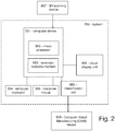
- Fig. 2 shows a schematic of a system according to an embodiment of the present invention.
- the system 950 comprises a computer device 951 comprising a computer readable medium 952 and a processor 953.
- the system further comprises a visual display unit 956, a computer keyboard 954 and a computer mouse 955 for entering data and activating virtual buttons visualized on the visual display unit 956.
- the visual display unit 956 can be a computer screen.
- the computer device 951 is capable of receiving a digital 3D representation of the patient's jaw from a scanning device 957, such as the TRIOS intra-oral scanner manufactured by 3shape TRIOS, or capable of receiving scan data from such a scanning device and forming a digital 3D representation of the patient's jaw based on such scan data.
- the received or formed digital 3D representation can be stored in the computer readable medium 952 and provided to the processor 953.
- the processor 953 is configured for performing the steps of the method according to any of the embodiments disclosed.
- the system comprises a unit 958 for transmitting the digital control guide design to e.g. a computer aided manufacturing (CAM) device 959 for manufacturing the control guide or to another computer system e.g. located at a milling center where the control guide is manufactured.
- the unit for transmitting the virtual 3D model can be a wired or a wireless connection.
- a claim may refer to any of the preceding claims, and "any” is understood to mean “any one or more” of the preceding claims.
- the features of the method described above and in the following may be implemented in software and carried out on a data processing system or other processing means caused by the execution of computer-executable instructions.
- the instructions may be program code means loaded in a memory, such as a RAM, from a storage medium or from another computer via a computer network.
- the described features may be implemented by hardwired circuitry instead of software or in combination with software.
Landscapes
- Health & Medical Sciences (AREA)
- Oral & Maxillofacial Surgery (AREA)
- Dentistry (AREA)
- Epidemiology (AREA)
- Life Sciences & Earth Sciences (AREA)
- Animal Behavior & Ethology (AREA)
- General Health & Medical Sciences (AREA)
- Public Health (AREA)
- Veterinary Medicine (AREA)
- Orthopedic Medicine & Surgery (AREA)
- Dental Tools And Instruments Or Auxiliary Dental Instruments (AREA)
Claims (4)
- Procédé mis en œuvre par ordinateur pour fournir une conception de guide de commande numérique d'un guide de commande (1) pour assurer la position et l'orientation d'au moins deux piliers dentaires (2, 3, 4) agencés sur au moins des premier et second emplacements cibles respectifs (5, 6, 7), dans lequel le procédé comprend les étapes consistant à- obtenir une représentation numérique 3D d'au moins une partie d'une mâchoire de patient comprenant au moins des premier et second emplacements cibles (5, 6, 7),- fournir un premier pilier dentaire numérique et un second pilier numérique, qui sont respectivement des représentations numériques 3D d'au moins un premier pilier dentaire (2) pour une mise en place sur le premier emplacement cible (5) et d'un second pilier dentaire (3) pour une mise en place sur le second emplacement cible (6),- agencer le premier pilier dentaire numérique sur la représentation numérique du premier emplacement cible et le second pilier dentaire numérique sur la représentation numérique du second emplacement cible,- déterminer des surfaces de contact des au moins premier et second piliers dentaires sur la base d'une direction d'insertion de la conception de guide de commande numérique en dérivant des surfaces visibles (14, 15, 16) des piliers respectifs (2, 3, 4) lorsqu'ils sont agencés au niveau des emplacements cibles (5, 6, 7) et vus le long de la direction d'insertion (ICG) de la conception de guide de commande numérique,- générer une conception de guide de commande numérique comprenant une représentation numérique 3D de la surface faisant face à la gencive du guide de commande sur la base d'au moins une partie des surfaces de contact à la fois des au moins premier et second piliers dentaires.
- Procédé mis en œuvre par ordinateur selon la revendication 1, dans lequel les surfaces de contact sont déterminées par une projection orthographique des au moins premier et second piliers dentaires numériques le long de la direction d'insertion.
- Procédé mis en œuvre par ordinateur selon la revendication 1 ou 2, dans lequel la représentation 3D de la surface faisant face à la gencive est basée sur toutes les surfaces de contact des premier et second piliers dentaires numériques.
- Procédé mis en œuvre par ordinateur pour fournir une conception de guide de commande numérique d'un guide de commande selon la revendication 1, 2 ou 3, dans lequel au moins l'un des piliers dentaires numériques représente un pilier dentaire retenu par vis comprenant un trou de vis et dans lequel un trou traversant est conçu dans la conception de guide de commande numérique qui s'étend coaxialement avec le trou de vis représenté dans le pilier dentaire numérique.
Applications Claiming Priority (1)
| Application Number | Priority Date | Filing Date | Title |
|---|---|---|---|
| DKPA201670278 | 2016-04-29 |
Publications (2)
| Publication Number | Publication Date |
|---|---|
| EP3238652A1 EP3238652A1 (fr) | 2017-11-01 |
| EP3238652B1 true EP3238652B1 (fr) | 2020-02-12 |
Family
ID=58638733
Family Applications (1)
| Application Number | Title | Priority Date | Filing Date |
|---|---|---|---|
| EP17168316.2A Active EP3238652B1 (fr) | 2016-04-29 | 2017-04-27 | Guide de commande pour vérifier le placement d'au moins deux éléments dentaires |
Country Status (2)
| Country | Link |
|---|---|
| US (1) | US20170312049A1 (fr) |
| EP (1) | EP3238652B1 (fr) |
Families Citing this family (1)
| Publication number | Priority date | Publication date | Assignee | Title |
|---|---|---|---|---|
| US10213274B1 (en) | 2018-03-12 | 2019-02-26 | King Saud University | Method of tracking and navigation for a dental instrument |
Family Cites Families (28)
| Publication number | Priority date | Publication date | Assignee | Title |
|---|---|---|---|---|
| US6382975B1 (en) * | 1997-02-26 | 2002-05-07 | Technique D'usinage Sinlab Inc. | Manufacturing a dental implant drill guide and a dental implant superstructure |
| US5725376A (en) * | 1996-02-27 | 1998-03-10 | Poirier; Michel | Methods for manufacturing a dental implant drill guide and a dental implant superstructure |
| US7887327B2 (en) * | 2001-08-31 | 2011-02-15 | Leonard Marotta | Accurate analogs for prostheses using computer generated anatomical models |
| US7086860B2 (en) * | 2002-02-20 | 2006-08-08 | Schuman Walter F | Implant placement system |
| US7044735B2 (en) * | 2003-05-02 | 2006-05-16 | Leo J. Malin | Method of installing a dental implant |
| US7153132B2 (en) * | 2005-05-23 | 2006-12-26 | Tedesco James L | Mini-dental implant surgical stent |
| EP1933757B1 (fr) * | 2005-08-26 | 2017-03-29 | siCAT GmbH & Co. KG | Ébauche utilisée comme gabarit de percage et pour enregistrer des enregistrements de données |
| US7845943B2 (en) * | 2006-09-07 | 2010-12-07 | Meitner Sean W | Method for making and using a template for locating a dental implant and components relating thereto |
| EP2103276B1 (fr) * | 2008-03-19 | 2019-06-19 | Nobel Biocare Services AG | Repositionnement de composants associés aux procédures chirurgicales crâniennes chez un patient |
| WO2010022479A2 (fr) * | 2008-08-29 | 2010-03-04 | De Clerck Rene | Méthode et élément de transfert servant à la fabrication d'une superstructure et d'un gabarit correspondant |
| US20100092910A1 (en) * | 2008-10-09 | 2010-04-15 | Asbel Rodrigues Machado | Reference support for a dental implant, a radiographic and/or tomographic reference support mounting frame and a prosthetic crown sounding guide |
| WO2010059692A2 (fr) * | 2008-11-18 | 2010-05-27 | Ibur, Llc | Dispositif et procédé dentaire pour lier des données physiques et numériques à des fins de diagnostic, de planification de traitements, de formation des patients, de communication, de fabrication et de transfert de données |
| US8529255B2 (en) * | 2009-01-16 | 2013-09-10 | V2R Biomedical Inc | Dental prosthesis system |
| DE102009010699C5 (de) * | 2009-02-27 | 2020-11-12 | Marcus Abboud | Bohrschablone zum Präparieren eines Patienten-Kieferknochens für ein medizinisches Zahn-Implantat |
| TW201034634A (en) * | 2009-03-19 | 2010-10-01 | Pou Yu Biotechnology Co Ltd | Production method of dental implant surgical guide |
| EP2238941B1 (fr) * | 2009-04-02 | 2015-01-14 | Straumann Holding AG | Procédé de fabrication d'un gabarit de perçage chirurgical |
| US20110111362A1 (en) * | 2009-11-11 | 2011-05-12 | Jerome Haber | Surgical guides |
| TWI448276B (zh) * | 2010-11-26 | 2014-08-11 | Po Kun Cheng | 牙齒定位模板及其製造方法 |
| DE102011003561A1 (de) * | 2011-02-03 | 2012-08-09 | Sirona Dental Systems Gmbh | Abdruck, Bohrschablone und Verfahren zur Bereitstellung einer Lagebeziehung und zur Erstellung einer Bohrschablone |
| ITFI20110130A1 (it) * | 2011-07-01 | 2013-01-02 | Leone Spa | Sistema di guida chirurgica per implantologia dentale e procedimento per la realizzazione di guide chirurgiche per implantologia dentale. |
| US20130023888A1 (en) * | 2011-07-22 | 2013-01-24 | Woncheol Choi | Surgical drill guide adapter with a handle and detachable head |
| US8892235B2 (en) * | 2011-12-05 | 2014-11-18 | Anatomage Inc. | Method and system for generating a dental implant surgical drill guide |
| JP6334409B2 (ja) * | 2011-12-21 | 2018-05-30 | 3シェイプ アー/エス | カスタマイズド治療用支台歯の仮想設計 |
| ES2873179T3 (es) * | 2012-05-10 | 2021-11-03 | Renishaw Plc | Método para fabricar un artículo |
| EP2877118B1 (fr) * | 2012-07-25 | 2020-10-21 | 3Shape A/S | Conception d'un gabarit de positionnement dentaire |
| US20140178832A1 (en) * | 2012-12-21 | 2014-06-26 | Anatomage Inc. | System and method for providing compact navigation-based surgical guide in dental implant surgery |
| US10064700B2 (en) * | 2013-02-14 | 2018-09-04 | Zvi Fudim | Surgical guide kit apparatus and method |
| JP6262179B2 (ja) * | 2014-12-05 | 2018-01-17 | ディオ コーポレーションDio Corporation | デンタルインプラント施術のための手術ガイドおよび植立物の製造方法 |
-
2017
- 2017-04-27 EP EP17168316.2A patent/EP3238652B1/fr active Active
- 2017-04-28 US US15/582,143 patent/US20170312049A1/en not_active Abandoned
Non-Patent Citations (1)
| Title |
|---|
| None * |
Also Published As
| Publication number | Publication date |
|---|---|
| EP3238652A1 (fr) | 2017-11-01 |
| US20170312049A1 (en) | 2017-11-02 |
Similar Documents
| Publication | Publication Date | Title |
|---|---|---|
| ES2841056T3 (es) | Dispositivo robótico para cirugía dental | |
| US10806542B2 (en) | Force-closure or form-closure positioning of surgical templates for guided implant dentistry | |
| KR101883345B1 (ko) | 치아 교정 시뮬레이션 장치에서의 치아 자동 교정 방법, 그 방법이 적용된 치아 교정 시뮬레이션 장치, 및 이를 저장하는 컴퓨터로 판독 가능한 기록 매체 | |
| US20080118895A1 (en) | Device and Procedure for Facilitating the Fitting of a Tooth or Tooth Remnant Template Into the Right Position | |
| US9949807B2 (en) | Drill guide for a dental implant and a method for fabricating a drill guide | |
| BR112019019203B1 (pt) | Método para preparar instrumentação odontológica | |
| US20150342464A1 (en) | Method for checking tooth positions | |
| EP4026513A1 (fr) | Système de support thérapeutique et dispositif d'alignement | |
| EP3171811B1 (fr) | Guide de forage | |
| JP2018516708A (ja) | 顎顔面矯正手術画像校正デザインシステム及びその方法 | |
| KR101801827B1 (ko) | 수술 가이드 시스템 및 방법 | |
| US10251731B2 (en) | Method for digital designing a dental restoration | |
| KR20210121093A (ko) | 시술지원시스템, 처리장치 및 플레이트 | |
| US10111728B2 (en) | Partial surgical guide | |
| EP3393396B1 (fr) | Procédé de conception d'une restauration et d'une coiffe de réduction | |
| EP3238652B1 (fr) | Guide de commande pour vérifier le placement d'au moins deux éléments dentaires | |
| EP3236879B1 (fr) | Utilisation d'un scan osseux par cbct (tomographie volumique à faisceau ouvert conique) pour concevoir un col implantaire dentaire | |
| CN114615951A (zh) | 利用混合现实引导牙科治疗的系统和方法 | |
| KR101701273B1 (ko) | 얼굴 대칭평가 장치 및 이를 제조하는 방법 | |
| ES2814231T3 (es) | Dispositivo para el uso en un procedimiento para la fabricación de una estructura de implante dental | |
| US10433938B2 (en) | Method for designing attachment abutments for attaching dentures to the mandible and/or maxilla | |
| US10307229B2 (en) | Method for constructing tooth surfaces of a dental prosthesis and for producing dental restorations | |
| EP3753527A1 (fr) | Dispositif de fixation amovible pour les cas edentulées | |
| JP2024054010A (ja) | 施術支援装置、施術支援方法及びプログラム | |
| KR102662370B1 (ko) | 임플란트 식립과 관련된 예상 오차 정보를 제공하는 방법 및 디바이스 |
Legal Events
| Date | Code | Title | Description |
|---|---|---|---|
| PUAI | Public reference made under article 153(3) epc to a published international application that has entered the european phase |
Free format text: ORIGINAL CODE: 0009012 |
|
| STAA | Information on the status of an ep patent application or granted ep patent |
Free format text: STATUS: THE APPLICATION HAS BEEN PUBLISHED |
|
| AK | Designated contracting states |
Kind code of ref document: A1 Designated state(s): AL AT BE BG CH CY CZ DE DK EE ES FI FR GB GR HR HU IE IS IT LI LT LU LV MC MK MT NL NO PL PT RO RS SE SI SK SM TR |
|
| AX | Request for extension of the european patent |
Extension state: BA ME |
|
| STAA | Information on the status of an ep patent application or granted ep patent |
Free format text: STATUS: REQUEST FOR EXAMINATION WAS MADE |
|
| 17P | Request for examination filed |
Effective date: 20180425 |
|
| RBV | Designated contracting states (corrected) |
Designated state(s): AL AT BE BG CH CY CZ DE DK EE ES FI FR GB GR HR HU IE IS IT LI LT LU LV MC MK MT NL NO PL PT RO RS SE SI SK SM TR |
|
| GRAP | Despatch of communication of intention to grant a patent |
Free format text: ORIGINAL CODE: EPIDOSNIGR1 |
|
| STAA | Information on the status of an ep patent application or granted ep patent |
Free format text: STATUS: GRANT OF PATENT IS INTENDED |
|
| RIC1 | Information provided on ipc code assigned before grant |
Ipc: A61B 17/17 20060101ALI20190801BHEP Ipc: A61C 1/08 20060101AFI20190801BHEP |
|
| INTG | Intention to grant announced |
Effective date: 20190826 |
|
| GRAS | Grant fee paid |
Free format text: ORIGINAL CODE: EPIDOSNIGR3 |
|
| GRAA | (expected) grant |
Free format text: ORIGINAL CODE: 0009210 |
|
| STAA | Information on the status of an ep patent application or granted ep patent |
Free format text: STATUS: THE PATENT HAS BEEN GRANTED |
|
| AK | Designated contracting states |
Kind code of ref document: B1 Designated state(s): AL AT BE BG CH CY CZ DE DK EE ES FI FR GB GR HR HU IE IS IT LI LT LU LV MC MK MT NL NO PL PT RO RS SE SI SK SM TR |
|
| REG | Reference to a national code |
Ref country code: GB Ref legal event code: FG4D |
|
| REG | Reference to a national code |
Ref country code: CH Ref legal event code: EP |
|
| REG | Reference to a national code |
Ref country code: AT Ref legal event code: REF Ref document number: 1231095 Country of ref document: AT Kind code of ref document: T Effective date: 20200215 |
|
| REG | Reference to a national code |
Ref country code: IE Ref legal event code: FG4D |
|
| REG | Reference to a national code |
Ref country code: DE Ref legal event code: R096 Ref document number: 602017011497 Country of ref document: DE |
|
| PG25 | Lapsed in a contracting state [announced via postgrant information from national office to epo] |
Ref country code: NO Free format text: LAPSE BECAUSE OF FAILURE TO SUBMIT A TRANSLATION OF THE DESCRIPTION OR TO PAY THE FEE WITHIN THE PRESCRIBED TIME-LIMIT Effective date: 20200512 Ref country code: RS Free format text: LAPSE BECAUSE OF FAILURE TO SUBMIT A TRANSLATION OF THE DESCRIPTION OR TO PAY THE FEE WITHIN THE PRESCRIBED TIME-LIMIT Effective date: 20200212 Ref country code: FI Free format text: LAPSE BECAUSE OF FAILURE TO SUBMIT A TRANSLATION OF THE DESCRIPTION OR TO PAY THE FEE WITHIN THE PRESCRIBED TIME-LIMIT Effective date: 20200212 |
|
| REG | Reference to a national code |
Ref country code: LT Ref legal event code: MG4D |
|
| REG | Reference to a national code |
Ref country code: NL Ref legal event code: MP Effective date: 20200212 |
|
| PG25 | Lapsed in a contracting state [announced via postgrant information from national office to epo] |
Ref country code: HR Free format text: LAPSE BECAUSE OF FAILURE TO SUBMIT A TRANSLATION OF THE DESCRIPTION OR TO PAY THE FEE WITHIN THE PRESCRIBED TIME-LIMIT Effective date: 20200212 Ref country code: LV Free format text: LAPSE BECAUSE OF FAILURE TO SUBMIT A TRANSLATION OF THE DESCRIPTION OR TO PAY THE FEE WITHIN THE PRESCRIBED TIME-LIMIT Effective date: 20200212 Ref country code: IS Free format text: LAPSE BECAUSE OF FAILURE TO SUBMIT A TRANSLATION OF THE DESCRIPTION OR TO PAY THE FEE WITHIN THE PRESCRIBED TIME-LIMIT Effective date: 20200612 Ref country code: SE Free format text: LAPSE BECAUSE OF FAILURE TO SUBMIT A TRANSLATION OF THE DESCRIPTION OR TO PAY THE FEE WITHIN THE PRESCRIBED TIME-LIMIT Effective date: 20200212 Ref country code: BG Free format text: LAPSE BECAUSE OF FAILURE TO SUBMIT A TRANSLATION OF THE DESCRIPTION OR TO PAY THE FEE WITHIN THE PRESCRIBED TIME-LIMIT Effective date: 20200512 Ref country code: GR Free format text: LAPSE BECAUSE OF FAILURE TO SUBMIT A TRANSLATION OF THE DESCRIPTION OR TO PAY THE FEE WITHIN THE PRESCRIBED TIME-LIMIT Effective date: 20200513 |
|
| PG25 | Lapsed in a contracting state [announced via postgrant information from national office to epo] |
Ref country code: NL Free format text: LAPSE BECAUSE OF FAILURE TO SUBMIT A TRANSLATION OF THE DESCRIPTION OR TO PAY THE FEE WITHIN THE PRESCRIBED TIME-LIMIT Effective date: 20200212 |
|
| PG25 | Lapsed in a contracting state [announced via postgrant information from national office to epo] |
Ref country code: CZ Free format text: LAPSE BECAUSE OF FAILURE TO SUBMIT A TRANSLATION OF THE DESCRIPTION OR TO PAY THE FEE WITHIN THE PRESCRIBED TIME-LIMIT Effective date: 20200212 Ref country code: SK Free format text: LAPSE BECAUSE OF FAILURE TO SUBMIT A TRANSLATION OF THE DESCRIPTION OR TO PAY THE FEE WITHIN THE PRESCRIBED TIME-LIMIT Effective date: 20200212 Ref country code: DK Free format text: LAPSE BECAUSE OF FAILURE TO SUBMIT A TRANSLATION OF THE DESCRIPTION OR TO PAY THE FEE WITHIN THE PRESCRIBED TIME-LIMIT Effective date: 20200212 Ref country code: LT Free format text: LAPSE BECAUSE OF FAILURE TO SUBMIT A TRANSLATION OF THE DESCRIPTION OR TO PAY THE FEE WITHIN THE PRESCRIBED TIME-LIMIT Effective date: 20200212 Ref country code: EE Free format text: LAPSE BECAUSE OF FAILURE TO SUBMIT A TRANSLATION OF THE DESCRIPTION OR TO PAY THE FEE WITHIN THE PRESCRIBED TIME-LIMIT Effective date: 20200212 Ref country code: SM Free format text: LAPSE BECAUSE OF FAILURE TO SUBMIT A TRANSLATION OF THE DESCRIPTION OR TO PAY THE FEE WITHIN THE PRESCRIBED TIME-LIMIT Effective date: 20200212 Ref country code: PT Free format text: LAPSE BECAUSE OF FAILURE TO SUBMIT A TRANSLATION OF THE DESCRIPTION OR TO PAY THE FEE WITHIN THE PRESCRIBED TIME-LIMIT Effective date: 20200705 Ref country code: ES Free format text: LAPSE BECAUSE OF FAILURE TO SUBMIT A TRANSLATION OF THE DESCRIPTION OR TO PAY THE FEE WITHIN THE PRESCRIBED TIME-LIMIT Effective date: 20200212 Ref country code: RO Free format text: LAPSE BECAUSE OF FAILURE TO SUBMIT A TRANSLATION OF THE DESCRIPTION OR TO PAY THE FEE WITHIN THE PRESCRIBED TIME-LIMIT Effective date: 20200212 |
|
| REG | Reference to a national code |
Ref country code: DE Ref legal event code: R097 Ref document number: 602017011497 Country of ref document: DE |
|
| REG | Reference to a national code |
Ref country code: AT Ref legal event code: MK05 Ref document number: 1231095 Country of ref document: AT Kind code of ref document: T Effective date: 20200212 |
|
| PG25 | Lapsed in a contracting state [announced via postgrant information from national office to epo] |
Ref country code: MC Free format text: LAPSE BECAUSE OF FAILURE TO SUBMIT A TRANSLATION OF THE DESCRIPTION OR TO PAY THE FEE WITHIN THE PRESCRIBED TIME-LIMIT Effective date: 20200212 |
|
| REG | Reference to a national code |
Ref country code: CH Ref legal event code: PL |
|
| PLBE | No opposition filed within time limit |
Free format text: ORIGINAL CODE: 0009261 |
|
| STAA | Information on the status of an ep patent application or granted ep patent |
Free format text: STATUS: NO OPPOSITION FILED WITHIN TIME LIMIT |
|
| 26N | No opposition filed |
Effective date: 20201113 |
|
| PG25 | Lapsed in a contracting state [announced via postgrant information from national office to epo] |
Ref country code: CH Free format text: LAPSE BECAUSE OF NON-PAYMENT OF DUE FEES Effective date: 20200430 Ref country code: LI Free format text: LAPSE BECAUSE OF NON-PAYMENT OF DUE FEES Effective date: 20200430 Ref country code: AT Free format text: LAPSE BECAUSE OF FAILURE TO SUBMIT A TRANSLATION OF THE DESCRIPTION OR TO PAY THE FEE WITHIN THE PRESCRIBED TIME-LIMIT Effective date: 20200212 Ref country code: IT Free format text: LAPSE BECAUSE OF FAILURE TO SUBMIT A TRANSLATION OF THE DESCRIPTION OR TO PAY THE FEE WITHIN THE PRESCRIBED TIME-LIMIT Effective date: 20200212 Ref country code: LU Free format text: LAPSE BECAUSE OF NON-PAYMENT OF DUE FEES Effective date: 20200427 |
|
| REG | Reference to a national code |
Ref country code: BE Ref legal event code: MM Effective date: 20200430 |
|
| PG25 | Lapsed in a contracting state [announced via postgrant information from national office to epo] |
Ref country code: PL Free format text: LAPSE BECAUSE OF FAILURE TO SUBMIT A TRANSLATION OF THE DESCRIPTION OR TO PAY THE FEE WITHIN THE PRESCRIBED TIME-LIMIT Effective date: 20200212 Ref country code: SI Free format text: LAPSE BECAUSE OF FAILURE TO SUBMIT A TRANSLATION OF THE DESCRIPTION OR TO PAY THE FEE WITHIN THE PRESCRIBED TIME-LIMIT Effective date: 20200212 Ref country code: BE Free format text: LAPSE BECAUSE OF NON-PAYMENT OF DUE FEES Effective date: 20200430 |
|
| PG25 | Lapsed in a contracting state [announced via postgrant information from national office to epo] |
Ref country code: IE Free format text: LAPSE BECAUSE OF NON-PAYMENT OF DUE FEES Effective date: 20200427 |
|
| PG25 | Lapsed in a contracting state [announced via postgrant information from national office to epo] |
Ref country code: TR Free format text: LAPSE BECAUSE OF FAILURE TO SUBMIT A TRANSLATION OF THE DESCRIPTION OR TO PAY THE FEE WITHIN THE PRESCRIBED TIME-LIMIT Effective date: 20200212 Ref country code: MT Free format text: LAPSE BECAUSE OF FAILURE TO SUBMIT A TRANSLATION OF THE DESCRIPTION OR TO PAY THE FEE WITHIN THE PRESCRIBED TIME-LIMIT Effective date: 20200212 Ref country code: CY Free format text: LAPSE BECAUSE OF FAILURE TO SUBMIT A TRANSLATION OF THE DESCRIPTION OR TO PAY THE FEE WITHIN THE PRESCRIBED TIME-LIMIT Effective date: 20200212 |
|
| PG25 | Lapsed in a contracting state [announced via postgrant information from national office to epo] |
Ref country code: MK Free format text: LAPSE BECAUSE OF FAILURE TO SUBMIT A TRANSLATION OF THE DESCRIPTION OR TO PAY THE FEE WITHIN THE PRESCRIBED TIME-LIMIT Effective date: 20200212 Ref country code: AL Free format text: LAPSE BECAUSE OF FAILURE TO SUBMIT A TRANSLATION OF THE DESCRIPTION OR TO PAY THE FEE WITHIN THE PRESCRIBED TIME-LIMIT Effective date: 20200212 |
|
| P01 | Opt-out of the competence of the unified patent court (upc) registered |
Effective date: 20230529 |
|
| PGFP | Annual fee paid to national office [announced via postgrant information from national office to epo] |
Ref country code: GB Payment date: 20240419 Year of fee payment: 8 |
|
| PGFP | Annual fee paid to national office [announced via postgrant information from national office to epo] |
Ref country code: DE Payment date: 20240418 Year of fee payment: 8 |
|
| PGFP | Annual fee paid to national office [announced via postgrant information from national office to epo] |
Ref country code: FR Payment date: 20240425 Year of fee payment: 8 |