EP3238221B1 - Wireless power receiving coil along a loop of a device - Google Patents
Wireless power receiving coil along a loop of a device Download PDFInfo
- Publication number
- EP3238221B1 EP3238221B1 EP15873863.3A EP15873863A EP3238221B1 EP 3238221 B1 EP3238221 B1 EP 3238221B1 EP 15873863 A EP15873863 A EP 15873863A EP 3238221 B1 EP3238221 B1 EP 3238221B1
- Authority
- EP
- European Patent Office
- Prior art keywords
- power receiving
- wireless power
- loop
- coil
- forming
- Prior art date
- Legal status (The legal status is an assumption and is not a legal conclusion. Google has not performed a legal analysis and makes no representation as to the accuracy of the status listed.)
- Active
Links
- 238000000034 method Methods 0.000 claims description 28
- 239000000463 material Substances 0.000 claims description 18
- 230000005540 biological transmission Effects 0.000 claims description 13
- 238000010586 diagram Methods 0.000 description 8
- 230000008878 coupling Effects 0.000 description 6
- 238000010168 coupling process Methods 0.000 description 6
- 238000005859 coupling reaction Methods 0.000 description 6
- 230000001939 inductive effect Effects 0.000 description 6
- 239000004984 smart glass Substances 0.000 description 4
- 230000015572 biosynthetic process Effects 0.000 description 3
- 238000005755 formation reaction Methods 0.000 description 3
- 230000004907 flux Effects 0.000 description 2
- 239000011521 glass Substances 0.000 description 2
- 230000003213 activating effect Effects 0.000 description 1
- 239000011324 bead Substances 0.000 description 1
- 238000006243 chemical reaction Methods 0.000 description 1
- 239000000696 magnetic material Substances 0.000 description 1
- 230000010355 oscillation Effects 0.000 description 1
Images


Classifications
-
- H04B5/79—
-
- H02J5/005—
-
- H—ELECTRICITY
- H01—ELECTRIC ELEMENTS
- H01F—MAGNETS; INDUCTANCES; TRANSFORMERS; SELECTION OF MATERIALS FOR THEIR MAGNETIC PROPERTIES
- H01F38/00—Adaptations of transformers or inductances for specific applications or functions
- H01F38/14—Inductive couplings
-
- H—ELECTRICITY
- H02—GENERATION; CONVERSION OR DISTRIBUTION OF ELECTRIC POWER
- H02J—CIRCUIT ARRANGEMENTS OR SYSTEMS FOR SUPPLYING OR DISTRIBUTING ELECTRIC POWER; SYSTEMS FOR STORING ELECTRIC ENERGY
- H02J50/00—Circuit arrangements or systems for wireless supply or distribution of electric power
- H02J50/10—Circuit arrangements or systems for wireless supply or distribution of electric power using inductive coupling
-
- H—ELECTRICITY
- H02—GENERATION; CONVERSION OR DISTRIBUTION OF ELECTRIC POWER
- H02J—CIRCUIT ARRANGEMENTS OR SYSTEMS FOR SUPPLYING OR DISTRIBUTING ELECTRIC POWER; SYSTEMS FOR STORING ELECTRIC ENERGY
- H02J7/00—Circuit arrangements for charging or depolarising batteries or for supplying loads from batteries
- H02J7/0042—Circuit arrangements for charging or depolarising batteries or for supplying loads from batteries characterised by the mechanical construction
-
- H02J7/025—
-
- H04B5/26—
Definitions
- a basic wireless charging system may include a wireless power transmitter unit (PTU) and a wireless power receiving unit (PRU).
- PTU wireless power transmitter unit
- PRU wireless power receiving unit
- a PTU may include a transmit (Tx) coil
- a PRU may include receive (Rx) coil.
- Magnetic resonance wireless charging may employ a magnetic coupling between the Tx coil and the Rx coil.
- wireless charging systems may be implemented as charging systems for wearable devices as opposed to, or even in addition to, traditional wired charging systems. Different implementations of wireless charging systems are described in EP 2 961 033 A1 , US 2007/268144 A1 , KR 2014 0049999 A , US 2011/062796 A1 , and US 2014/143933 A1 .
- wearable computing devices vary in shape and size making it challenging to find a flat surface to embed a wireless power Rx coil.
- a wireless power Rx coil may be a component in a power receiving unit (PRU), while a wireless power Tx coil may be a component in a power transmitting unit (PTU), as discussed in more detail below.
- a wireless power Rx coil may be a component in a power receiving unit (PRU)
- a wireless power Tx coil may be a component in a power transmitting unit (PTU), as discussed in more detail below.
- load modulation may be implemented via a direct current to direct current (DC2DC) converter 120 of the PRU 104.
- the DC2DC converter 120 is an electronic circuit configured to convert a direct current (DC) from one voltage level to another after receiving the voltage from a matching network rectifier 122. As illustrated in Fig. 1 , the DC2DC converter 120 provides a DC output to a battery 124, or another current/power consuming component.
- the DC2DC converter 120 may convert DC received as a result of the inductive coupling of the Tx coil 106 and the Rx coil 108.
- the controller 114 may direct the DC2DC converter 120 to vary the conversion such that a load is modulated and detectable by the PTU 102.
- the controller 114 may turn the DC2DC converter 128 on and off, resulting in a load modulation detectable at the PTU 102.
- the modulated load is achieved by a lower load than the normal load observed when the DC2DC converter is running normally.
- a wireless broadcast such as a load achieved by activating a shunt resistor, are contemplated by the techniques described herein.
- the varying resonance frequency of the Rx coil 108 due to the varying length of the loop of the device 112 may be compensated for at the PTU 102 after the wireless data broadcast signal is received at the PTU 102.
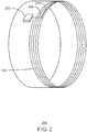
- Fig. 2 is an illustration of perspective view of a device having an embedded wireless Rx coil.
- the device 112 of Fig. 1 is a wirelessly chargeable bracelet 200 having an Rx coil, such as the Rx coil 108 of the PRU 104 of Fig. 1 .
- the Rx coil 108 may be connected to an integrated circuit 202.
- the integrated circuit 202 may include one or more of the components in a PRU, such as the PRU 104 of Fig. 1 .
- each turn of the Rx coil 108 extends along the entire length of a loop of the wirelessly chargeable bracelet 200.
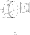
- Fig. 4 is an illustration of a perspective view and a close up view of a device having an embedded wireless Rx coil and a flexible portion.
- the device 112 may have a loop that is composed of at least a portion of flexible material.
- the wirelessly chargeable bracelet 200 may include the Rx coil 108 having a flexible portion 402.
- turns of the Rx coil 108 may be formed in a zigzag.
- Other formations of the flexible portion 402 may be implemented such as circular formation, a coiled formation, and the like. This implementation may enable the wirelessly chargeable bracelet 200 to be removed from an arm of a user for example by stretching the flexible portion 402.
- the implementations of the device 112 of Fig. 1 described herein may provide possibilities to increase efficiency of wireless charging.
- a larger inductive area is formed, than if the Rx coil 108 was placed on a surface without each turn following the entire length of the loop.
- the larger area may enable a larger magnetic flux to be couple to the Rx coil 108 when placed on a charging coil, such as the PTU 102 of Fig. 1 .
- magnetic flux further away, or at an increased "Z" height from the PTU 102 may be coupled to the Rx coil 108, and some stray fields associated with the PTU 102 may be coupled to the Rx coil 108.
- forming the device includes at least a portion of expandable material.
- the forming the wireless power receiving coil includes forming an expandable portion embedded within the portion of the expandable material of the device.
- the method 800 includes any combination of the cases discussed above.
- the device and coil may be formed with expandable portions, foldable portions, detachable connectors and receivers, or any combination thereof.
- Example 1 includes an apparatus for wireless charging.
- the apparatus includes a device formed in a loop, and a wireless power receiving coil disposed around an entire length of the loop. Each turn of the wireless power receiving coil follows the entire length of the loop.
- Example 1 may include any combination of the cases and situations described below.
- the apparatus includes a wireless data transmission component to broadcast a data signal.
- a length of the loop is variable based on characteristics of the device.
- the broadcast data signal may include data indicating a resonance frequency of the wireless power receiving coil based, in part, on the variable length of the wireless power receiving coil.
- the device includes at least a portion of expandable material.
- the wireless power receiving coil may include an expandable portion embedded within the portion of the expandable material of the device.
- Example 2 includes a method of forming a device for wireless charging.
- the method may include forming a device having a loop, and embedding a wireless power receiving coil disposed around an entire length of the loop. Each turn of the wireless power receiving coil follows the entire length of the loop.
- Example 2 may include any combination of the cases and situations described below.
- the method includes embedding a wireless data transmission component within the device to broadcast a data signal.
- a length of the loop may be variable based on characteristics of the device.
- the broadcast data signal may include data indicating a resonance frequency of the wireless power receiving unit based, in part, on the variable length of the wireless power receiving coil.
- forming the device includes forming at least a portion of expandable material.
- Forming the wireless power receiving coil may include forming an expandable portion embedded within the portion of the expandable material of the device.
- forming the device includes forming a foldable portion.
- Forming the wireless power receiving coil comprises forming a foldable portion embedded within the foldable portion of the device.
- the method may include forming detachable connectors to unloop the device.
- the detachable connectors comprise conductive connectors that when attached to each other close an electrical circuit of the wireless power receiving coil.
- the wearable computing device includes at least a portion of expandable material.
- the wireless power receiving coil may include an expandable portion embedded within the portion of the expandable material of the wearable computing device.
- the wearable computing device includes a detachable portion.
- the wireless power receiving coil may include a detachable portion embedded within the detachable portion of the wireless power receiving coil.
- the wearable computing device includes a foldable portion.
- the wireless power receiving coil may include a foldable portion embedded within the foldable portion of the wearable computing device.
- the apparatus may include detachable connectors to unloop the device.
- the detachable connectors comprise conductive connectors that when attached to each other close an electrical circuit of the means for wireless power receiving.
- forming the device includes forming a detachable portion.
- Forming the means for wireless power receiving comprises forming a detachable portion embedded within the detachable portion of the means for wireless power receiving.
- the method may include forming detachable connectors to unloop the device.
- the detachable connectors comprise conductive connectors that when attached to each other close an electrical circuit of the means for wireless power receiving.
- the elements in some cases may each have a same reference number or a different reference number to suggest that the elements represented could be different and/or similar.
- an element may be flexible enough to have different implementations and work with some or all of the systems shown or described herein.
- the various elements shown in the figures may be the same or different. Which one is referred to as a first element and which is called a second element is arbitrary.
Description
- This disclosure relates generally to techniques for wireless charging. Specifically, this disclosure relates to wireless power receiving coil formed in a loop of a device.
- A basic wireless charging system may include a wireless power transmitter unit (PTU) and a wireless power receiving unit (PRU). For example, a PTU may include a transmit (Tx) coil, and a PRU may include receive (Rx) coil. Magnetic resonance wireless charging may employ a magnetic coupling between the Tx coil and the Rx coil. As wearable computing devices become increasingly popular, wireless charging systems may be implemented as charging systems for wearable devices as opposed to, or even in addition to, traditional wired charging systems. Different implementations of wireless charging systems are described in
EP 2 961 033 A1 ,US 2007/268144 A1 ,KR 2014 0049999 A US 2011/062796 A1 , andUS 2014/143933 A1 . However, in many cases, wearable computing devices vary in shape and size making it challenging to find a flat surface to embed a wireless power Rx coil. -
-
Fig. 1 is block diagram of a PTU to provide power to a PRU having an Rx coil embedded in a loop of a device; -
Fig. 2 is an illustration of perspective view of a device having an embedded wireless Rx coil; -
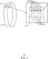
Fig. 3 is an illustration of a perspective view and a close up view of a device having an embedded wireless Rx coil and a break point; -
Fig. 4 is an illustration of a perspective view and a close up view of a device having an embedded wireless Rx coil and a flexible portion; -
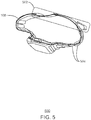
Fig. 5 is an illustration of a side view of a device having an embedded wireless Rx coil and a foldable portion; -
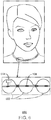
Fig. 6 is an illustration of a front view and a close up view of a device having an embedded wireless Rx coil; -
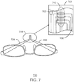
Fig. 7 is an illustration of a perspective view and a close up view of a device having an embedded wireless Rx coil and a connectable portion to close the loop; and -
Fig. 8 is a flow diagram of a method for forming a device for wireless charging. - The same numbers are used throughout the disclosure and the figures to reference like components and features. Numbers in the 100 series refer to features originally found in
Fig. 1 ; numbers in the 200 series refer to features originally found inFig. 2 ; and so on. - The present disclosure relates generally to techniques for embedding a wireless power receiving (Rx) coil within a computing device having a looped shape. For example, a wearable computing device may include a bracelet having various sensors. In this scenario, the wireless power Rx coil is embedded in the loop wherein each turn of the Rx coil follows the entire length of the loop. More specifically, a first turn will follow the entire length of the loop and connect to a second turn following the entire length of the loop, and so on. The techniques described herein may improve efficiency of wireless charging as the wireless Rx coil may be relatively larger than if the wireless Rx coil did not follow the entire length of the loop.
- In some cases, the techniques discussed herein may be implemented using a wireless charging standard protocol, such as the specification provided by Alliance For Wireless Power (A4WP) version 1.2.1, May 07, 2014. A wireless power Rx coil may be a component in a power receiving unit (PRU), while a wireless power Tx coil may be a component in a power transmitting unit (PTU), as discussed in more detail below.
-
Fig. 1 is block diagram of a PTU to provide power to a PRU having an Rx coil embedded in a loop of a device. A PTU 102 may couple to a PRU 104 via magnetic inductive coupling betweenresonators arrow 110. Theresonator 106 may be referred to herein as aTx coil 106 of thePTU 102. Theresonator 108 may be referred to herein as aRx coil 108 of the PRU 104. - As discussed above, the
Rx coil 108, as well as other components of discussed below, may be embedded in a device having a loop, as indicated at 112. Thedevice 112 may be a wearable device, such as a smart watch, smart bracelet, smart necklace, smart glasses, and the like. Different implementations of thedevice 112 are discussed below in regard toFigs. 2-7 . As illustrated and discussed in more detail below, the loop of thedevice 112 may be a result of a shape of thedevice 112. In some cases, such as in wearable computing glasses, the loop may be formed as a result of connecting ends of stems of the glasses. In any case, thedevice 112 includes aRx coil 108 embedded within the loop such that each turn of theRx coil 108 may follow an entire length of the loop. - The PRU 104 may include a
controller 114 configured to detect current received at theRx coil 108 resulting from an inductive coupling between theTx coil 106 and theRx coil 108. In some cases, thecontroller 114 may be configured to initiate a wireless data broadcast indicating a resonant frequency of theRx coil 108. As discussed in more detail below, a length of the loop of thedevice 112 may be variable due to flexible portions of the loop, removable portions of the loop, foldable portions of the loop, and the like. As the length of the loop changes, the resonant frequency associated with theRx coil 108 may also change. Therefore, the PRU 104 may include wireless data transmission component to broadcast a data signal indicating a resonance frequency of theRx coil 108 based, in part, on the variable length. - The wireless data transmission component may be Bluetooth Low Energy (BLE)
module 116 in some cases. In some cases, the wireless data transmission component may be integrated as operations of thecontroller 114 and aload modulation circuit 118, wherein the data transmission may be indicated by patterns in the load modulation. - Further, load modulation may be implemented via a direct current to direct current (DC2DC)
converter 120 of the PRU 104. TheDC2DC converter 120 is an electronic circuit configured to convert a direct current (DC) from one voltage level to another after receiving the voltage from amatching network rectifier 122. As illustrated inFig. 1 , theDC2DC converter 120 provides a DC output to abattery 124, or another current/power consuming component. TheDC2DC converter 120 may convert DC received as a result of the inductive coupling of theTx coil 106 and theRx coil 108. In order to perform modulation, thecontroller 114 may direct theDC2DC converter 120 to vary the conversion such that a load is modulated and detectable by thePTU 102. In other examples, thecontroller 114 may turn theDC2DC converter 128 on and off, resulting in a load modulation detectable at thePTU 102. In this example, by turning off theDC2DC converter 120, the modulated load is achieved by a lower load than the normal load observed when the DC2DC converter is running normally. Other examples of a wireless broadcast, such as a load achieved by activating a shunt resistor, are contemplated by the techniques described herein. In any case, the varying resonance frequency of theRx coil 108 due to the varying length of the loop of thedevice 112 may be compensated for at thePTU 102 after the wireless data broadcast signal is received at thePTU 102. - The PTU 102 may include a
BLE module 126 configured to communicate with theBLE module 116. ThePTU 102 may also include acurrent sensor 128, acontroller 130, apower amplifier 132, aDC2DC converter 134, anoscillator 136, and amatching network 138. Theinductive coupling 110 may cause an initial load change detected by thecurrent sensor 128 of thePTU 102. Thecurrent sensor 128 may be an ampere meter, a volt meter, or any other meter configured to sense load variations occurring due to inductive coupling between thePTU 102 and another object, such as the PRU 104. Thecurrent sensor 128 may provide an indication of load change to acontroller 130 of thePTU 102. Thecontroller 130 may power on thepower amplifier 132 configured to receive direct current (DC) from theDC2DC converter 134, and to amplify and oscillate the current. Anoscillator 136 may oscillate the power provided at a given frequency and amatching network 138 may be used to match the amplified oscillation provided to theresonator 106 of thePTU 102. - The block diagram of
Fig. 1 is not intended to indicate that thedevice 110 is to include all of the components shown inFig. 1 . Further, thedevice 110 or may include any number of additional components not shown inFig. 1 , depending on the details of the specific implementation, as long thedevice 110 may be formed in a loop having theRx coil 108 embedded along the length of the loop, as described in more detail below. -
Fig. 2 is an illustration of perspective view of a device having an embedded wireless Rx coil. In this example, thedevice 112 ofFig. 1 is a wirelesslychargeable bracelet 200 having an Rx coil, such as theRx coil 108 of the PRU 104 ofFig. 1 . TheRx coil 108 may be connected to anintegrated circuit 202. Theintegrated circuit 202 may include one or more of the components in a PRU, such as the PRU 104 ofFig. 1 . As illustrated inFig. 2 , each turn of theRx coil 108 extends along the entire length of a loop of the wirelesslychargeable bracelet 200. For example, a first turn of theRx coil 106 indicated at 204 follows the length the loop of the wirelesslychargeable bracelet 200, and connects to a second turn of theRx coil 108 indicated at 206. Other examples of thedevice 112 ofFig. 1 may be implemented. -
Fig. 3 is an illustration of a perspective view and a close up view of a device having an embedded wireless Rx coil and a break point. In this example, the wirelessly chargeable bracelet, generally indicated at 200, may include adetachable section 302. As illustrated in a close upview 304, thedetachable portion 302 may includedetachable connectors 306 that may be received atreceivers 308. In some cases, thereceivers 308 may be holes defined in a cross section of the wirelesslychargeable bracelet 200. In some cases, thedetachable connectors 306 may be implemented as magnetic conductive components wherein thedetachable connectors 306 magnetically attach to thereceivers 308. In any case, when thedetachable connectors 306 are received at thereceivers 308, a circuit associated with theRx coil 108 is completed, and wireless power may be received from a PTU, such as the PTU ofFig. 1 . This implementation may enable the wirelesslychargeable bracelet 200 to be removed from an arm of a user for example by opening the detachable portion. -
Fig. 4 is an illustration of a perspective view and a close up view of a device having an embedded wireless Rx coil and a flexible portion. As discussed above in regard toFig. 1 , thedevice 112 may have a loop that is composed of at least a portion of flexible material. In this scenario, the wirelesslychargeable bracelet 200 may include theRx coil 108 having aflexible portion 402. As illustrated in the close up view 404 of theflexible portion 402 of theRx coil 108, turns of theRx coil 108 may be formed in a zigzag. Other formations of theflexible portion 402 may be implemented such as circular formation, a coiled formation, and the like. This implementation may enable the wirelesslychargeable bracelet 200 to be removed from an arm of a user for example by stretching theflexible portion 402. -
Fig. 5 is an illustration of a side view of a device having an embedded wireless Rx coil and a foldable portion. In this example, thedevice 112 ofFig. 1 is a wirelessly chargeablesmart watch 500 having an Rx coil, such as theRx coil 108 of the PRU 104 ofFig. 1 . A loop of the wirelessly chargeablesmart watch 500 may include a foldable portion, generally indicated by the dashedbox 502. In this example, theRx coil 108 may be foldable at thefoldable portion 502. This implementation may enable the wirelessly chargeablesmart watch 500 to be removed an arm of a user, for example, by unfolding thefoldable portion 502. Further, as indicated at 504, a band of the wirelessly chargeablesmart watch 500 may include removable sections. In this scenario,removable sections 504 may be connectable by detachable connectors and receivers, such as thedetachable connectors 306 andreceivers 308 ofFig. 3 . In some cases, the wirelessly chargeablesmart watch 500 may be formed of a non-magnetic material such that the material will not interfere with wireless charging of theRx coil 108. -
Fig. 6 is an illustration of a front view and a close up view of a device having an embedded wireless Rx coil. In this example, thedevice 112 ofFig. 1 is a wirelesslychargeable necklace 602 having an Rx coil, such as theRx coil 108 of the PRU 104 ofFig. 1 . TheRx coil 108 may be connected to anintegrated circuit 604. Theintegrated circuit 604 may include one or more of the components in a PRU, such as the PRU 104 ofFig. 1 . As illustrated in the close up view 606, each turn of theRx coil 108 may extend along the entire length of a loop of the wirelesslychargeable necklace 602. Although not illustrated inFig. 6 , similar toFig. 3 andFig. 5 , the wirelesslychargeable necklace 602 may include one or removable sections, or detachable connectors between beads 608 of the wirelesslychargeable necklace 602. This implementation may enable the wirelesslychargeable necklace 602 to be removed a neck of a user, for example, by detaching the detachable connectors. -
Fig. 7 is an illustration of a perspective view and a close up view of a device having an embedded wireless Rx coil and a connectable portion to close the loop. While examples of thedevice 112 ofFig. 1 may be configured to be worn in a loop, thedevice 112 may also include devices that may be formed into a loop for wireless charging, as illustrated with a wirelessly chargeablesmart glass 702 ofFig. 7 . In this example, thedevice 112 ofFig. 1 is the wirelessly chargeablesmart glass 702 having an Rx coil, such as theRx coil 108 of the PRU 104 ofFig. 1 . TheRx coil 108 may be connected to anintegrated circuit 702. Theintegrated circuit 702 may include one or more of the components in a PRU, such as the PRU 104 ofFig. 1 . - The loop may be formed by connecting stems 704 and 706 together, as indicated by the
circle 708. As illustrated in the close upview 710, each turn of theRx coil 108 may extend along the entire length of a loop of the wirelessly chargeablesmart glass 702. The stems 704 and 706 may include detachable connectors and receivers, such as thedetachable connectors 306 andreceivers 308 ofFig. 3 , as indicated by the dashedcircle 712. - The implementations of the
device 112 ofFig. 1 described herein may provide possibilities to increase efficiency of wireless charging. By integrating theRx coil 108 as a part of a loop in thedevice 112 structure, a larger inductive area is formed, than if theRx coil 108 was placed on a surface without each turn following the entire length of the loop. The larger area may enable a larger magnetic flux to be couple to theRx coil 108 when placed on a charging coil, such as thePTU 102 ofFig. 1 . Further, magnetic flux further away, or at an increased "Z" height from thePTU 102 may be coupled to theRx coil 108, and some stray fields associated with thePTU 102 may be coupled to theRx coil 108. -
Fig. 8 is a flow diagram of a method for forming a device for wireless charging. Themethod 800 may include forming a device having a loop atblock 802. As discussed above in regard toFig. 8 , the device need not be formed in a loop necessarily, but may be formed to have a loop in certain dispositions. Atblock 804, a wireless power receiving coil disposed around an entire length of the loop. Each turn of the wireless power receiving coil follows the entire length of the loop. - In some cases, the method may include embedding a wireless data transmission component to broadcast a data signal. As discussed above in regard to
Fig. 1 , the wireless data transmission component may be a BLE module, or may be implemented with load modulation via various components of a PRU, such as the PRU 104 ofFig. 1 . - In some cases, the length of the loop may be formed to be variable. The broadcast data signal includes data indicating a resonance frequency of the wireless power receiving unit based, in part, on the variable length of the wireless power receiving coil.
- In some cases, forming the device includes at least a portion of expandable material. In this case, the forming the wireless power receiving coil includes forming an expandable portion embedded within the portion of the expandable material of the device.
- In some cases, forming the device includes forming a detachable portion. In this scenario, forming the wireless power receiving coil includes forming a detachable portion embedded within the detachable portion of the wireless power receiving coil.
- In some cases, forming the device comprises forming a foldable portion. In this scenario, forming the wireless power receiving coil comprises forming a foldable portion embedded within the foldable portion of the device.
- In some cases, the
method 800 further includes forming detachable connectors to unloop the device. In this scenario, the detachable connectors comprise conductive connectors that when attached to each other close an electrical circuit of the wireless power receiving coil. - Further, in some cases, the
method 800 includes any combination of the cases discussed above. For example, the device and coil may be formed with expandable portions, foldable portions, detachable connectors and receivers, or any combination thereof. - Not all components, features, structures, characteristics, etc. described and illustrated herein need be included in a particular aspect or aspects. If the specification states a component, feature, structure, or characteristic "may", "might", "can" or "could" be included, for example, that particular component, feature, structure, or characteristic is not required to be included. If the specification or claim refers to "a" or "an" element, that does not mean there is only one of the element. If the specification or claims refer to "an additional" element, that does not preclude there being more than one of the additional element.
- Example 1 includes an apparatus for wireless charging. The apparatus includes a device formed in a loop, and a wireless power receiving coil disposed around an entire length of the loop. Each turn of the wireless power receiving coil follows the entire length of the loop.
- Example 1 may include any combination of the cases and situations described below. In some cases, the apparatus includes a wireless data transmission component to broadcast a data signal. A length of the loop is variable based on characteristics of the device. The broadcast data signal may include data indicating a resonance frequency of the wireless power receiving coil based, in part, on the variable length of the wireless power receiving coil.
- In some cases, the device includes at least a portion of expandable material. The wireless power receiving coil may include an expandable portion embedded within the portion of the expandable material of the device.
- In some cases, the device includes a detachable portion. The wireless power receiving coil may include a detachable portion embedded within the detachable portion of the wireless power receiving coil.
- In some cases, the device includes a foldable portion. The wireless power receiving coil may include a foldable portion embedded within the foldable portion of the device.
- In some cases, the apparatus may include detachable connectors to unloop the device. The detachable connectors comprise conductive connectors that when attached to each other close an electrical circuit of the wireless power receiving coil.
- Example 2 includes a method of forming a device for wireless charging. The method may include forming a device having a loop, and embedding a wireless power receiving coil disposed around an entire length of the loop. Each turn of the wireless power receiving coil follows the entire length of the loop.
- Example 2 may include any combination of the cases and situations described below. In some cases, the method includes embedding a wireless data transmission component within the device to broadcast a data signal. A length of the loop may be variable based on characteristics of the device. The broadcast data signal may include data indicating a resonance frequency of the wireless power receiving unit based, in part, on the variable length of the wireless power receiving coil.
- In some cases, forming the device includes forming at least a portion of expandable material. Forming the wireless power receiving coil may include forming an expandable portion embedded within the portion of the expandable material of the device.
- In some cases, forming the device includes forming a detachable portion. Forming the wireless power receiving coil comprises forming a detachable portion embedded within the detachable portion of the wireless power receiving coil.
- In some cases, forming the device includes forming a foldable portion. Forming the wireless power receiving coil comprises forming a foldable portion embedded within the foldable portion of the device.
- In some cases, the method may include forming detachable connectors to unloop the device. The detachable connectors comprise conductive connectors that when attached to each other close an electrical circuit of the wireless power receiving coil.
- Example 3 includes an system for wireless charging. The system includes a wearable computing device formed in a loop, and a wireless power receiving coil disposed around an entire length of the loop. Each turn of the wireless power receiving coil follows the entire length of the loop.
- Example 3 may include any combination of the cases and situations described below. In some cases, the system includes a wireless data transmission component to broadcast a data signal. A length of the loop is variable based on characteristics of the wearable computing device. The broadcast data signal may include data indicating a resonance frequency of the wireless power receiving coil based, in part, on the variable length of the wireless power receiving coil.
- In some cases, the wearable computing device includes at least a portion of expandable material. The wireless power receiving coil may include an expandable portion embedded within the portion of the expandable material of the wearable computing device.
- In some cases, the wearable computing device includes a detachable portion. The wireless power receiving coil may include a detachable portion embedded within the detachable portion of the wireless power receiving coil.
- In some cases, the wearable computing device includes a foldable portion. The wireless power receiving coil may include a foldable portion embedded within the foldable portion of the wearable computing device.
- In some cases, the system may include detachable connectors to unloop the wearable computing device. The detachable connectors comprise conductive connectors that when attached to each other close an electrical circuit of the wireless power receiving coil.
- Example 4 includes an apparatus for wireless charging. The apparatus includes a device formed in a loop, and a means for wireless power receiving disposed around an entire length of the loop. Each turn of the means for wireless power receiving follows the entire length of the loop.
- Example 4 may include any combination of the cases and situations described below. In some cases, the apparatus includes a wireless data transmission component to broadcast a data signal. A length of the loop is variable based on characteristics of the device. The broadcast data signal may include data indicating a resonance frequency of the means for wireless power receiving based, in part, on the variable length of the means for wireless power receiving.
- In some cases, the device includes at least a portion of expandable material. The means for wireless power receiving may include an expandable portion embedded within the portion of the expandable material of the device.
- In some cases, the device includes a detachable portion. The means for wireless power receiving may include a detachable portion embedded within the detachable portion of the means for wireless power receiving.
- In some cases, the device includes a foldable portion. The means for wireless power receiving may include a foldable portion embedded within the foldable portion of the device.
- In some cases, the apparatus may include detachable connectors to unloop the device. The detachable connectors comprise conductive connectors that when attached to each other close an electrical circuit of the means for wireless power receiving.
- Example 5 includes a method of forming a device for wireless charging. The method may include forming a device having a loop, and embedding a means for wireless power receiving disposed around an entire length of the loop. Each turn of the means for wireless power receiving follows the entire length of the loop.
- Example 5 may include any combination of the cases and situations described below. In some cases, the method includes embedding a wireless data transmission component within the device to broadcast a data signal. A length of the loop may be variable based on characteristics of the device. The broadcast data signal may include data indicating a resonance frequency of the wireless power receiving unit based, in part, on the variable length of the means for wireless power receiving.
- In some cases, forming the device includes forming at least a portion of expandable material. Forming the means for wireless power receiving may include forming an expandable portion embedded within the portion of the expandable material of the device.
- In some cases, forming the device includes forming a detachable portion. Forming the means for wireless power receiving comprises forming a detachable portion embedded within the detachable portion of the means for wireless power receiving.
- In some cases, forming the device includes forming a foldable portion. Forming the means for wireless power receiving comprises forming a foldable portion embedded within the foldable portion of the device.
- In some cases, the method may include forming detachable connectors to unloop the device. The detachable connectors comprise conductive connectors that when attached to each other close an electrical circuit of the means for wireless power receiving.
- It is to be noted that, although some aspects have been described in reference to particular implementations, other implementations are possible according to some aspects. Additionally, the arrangement and/or order of circuit elements or other features illustrated in the drawings and/or described herein need not be arranged in the particular way illustrated and described. Many other arrangements are possible according to some aspects.
- In each system shown in a figure, the elements in some cases may each have a same reference number or a different reference number to suggest that the elements represented could be different and/or similar. However, an element may be flexible enough to have different implementations and work with some or all of the systems shown or described herein. The various elements shown in the figures may be the same or different. Which one is referred to as a first element and which is called a second element is arbitrary.
- It is to be understood that specifics in the aforementioned examples may be used anywhere in one or more aspects. For instance, all optional features of the computing device described above may also be implemented with respect to either of the methods or the computer-readable medium described herein. Furthermore, although flow diagrams and/or state diagrams may have been used herein to describe aspects, the techniques are not limited to those diagrams or to corresponding descriptions herein. For example, flow need not move through each illustrated box or state or in exactly the same order as illustrated and described herein.
- The present techniques are not restricted to the particular details listed herein. Indeed, those skilled in the art having the benefit of this disclosure will appreciate that many other variations from the foregoing description and drawings may be made within the scope of the present techniques. Accordingly, it is the following claims including any amendments thereto that define the scope of the present techniques.
Claims (11)
- An apparatus for wireless charging, comprising:a device (112) formed in a loop, wherein a length of the loop is variable based on characteristics of the device; anda means for wireless power receiving (108) disposed around an entire length of the loop, wherein each turn of the means for wireless power receiving follows the entire length of the loop;a wireless data transmission component (114) to broadcast a data signal, wherein the broadcast data signal comprises data indicating a resonance frequency of the means for wireless power receiving (108) based, in part, on the variable length of the means for wireless power receiving.
- The apparatus of claim 1, wherein the device (112) is comprised of at least a portion of expandable material.
- The apparatus of any one of the previous claims, wherein the means for wireless power receiving (108) comprises an expandable portion (402) embedded within the portion of the expandable material of the device.
- The apparatus of any combination of the previous claims, wherein the device (112) comprises a detachable portion (302), and wherein the means for wireless power receiving (108) comprises a detachable portion (304) embedded within the detachable portion of the means for wireless power receiving.
- The apparatus of any combination of the previous claims, wherein the device (112) comprises a foldable portion (502), wherein the means for wireless power receiving (108) comprises a foldable portion embedded within the foldable portion of the device.
- The apparatus of any combination of the previous claims, further comprising detachable connectors (306) to unloop the device (112).
- The apparatus of claim 6, wherein the detachable connectors comprise conductive connectors that when attached to each other close an electrical circuit of the means for wireless power receiving.
- A method (800) of forming a device for wireless charging, comprising:forming (802) a device (112) having a loop; andembedding (804) a wireless power receiving coil (108) disposed around an entire length of the loop, wherein each turn of the wireless power receiving coil follows the entire length of the loop,further comprising embedding a wireless data transmission component (114) within the device (112) to broadcast a data signal, wherein a length of the loop is variable based on characteristics of the device, and wherein the broadcast data signal is to comprise data indicating a resonance frequency of the wireless power receiving unit based, in part, on the variable length of the wireless power receiving coil (108).
- The method (800) of claim 8, wherein forming (802) the device comprises forming at least a portion of expandable material, and wherein forming the wireless power receiving coil (108) comprises forming an expandable portion embedded within the portion of the expandable material of the device.
- The method (800) of any combination of claims 8 or 9, wherein forming (802) the device comprises forming a detachable portion, and wherein forming the wireless power receiving coil comprises forming a detachable portion embedded within the detachable portion of the wireless power receiving coil.
- The method of (800) any combination of claims 8-10, further comprising forming detachable connectors (306) to unloop the device, wherein the detachable connectors comprise conductive connectors that when attached to each other close an electrical circuit of the wireless power receiving coil (108).
Applications Claiming Priority (2)
| Application Number | Priority Date | Filing Date | Title |
|---|---|---|---|
| US14/580,616 US10200087B2 (en) | 2014-12-23 | 2014-12-23 | Wireless power receiving coil along a loop of a device |
| PCT/US2015/054166 WO2016105623A1 (en) | 2014-12-23 | 2015-10-06 | Wireless power receiving coil along a loop of a device |
Publications (3)
| Publication Number | Publication Date |
|---|---|
| EP3238221A1 EP3238221A1 (en) | 2017-11-01 |
| EP3238221A4 EP3238221A4 (en) | 2018-08-08 |
| EP3238221B1 true EP3238221B1 (en) | 2019-11-27 |
Family
ID=56130579
Family Applications (1)
| Application Number | Title | Priority Date | Filing Date |
|---|---|---|---|
| EP15873863.3A Active EP3238221B1 (en) | 2014-12-23 | 2015-10-06 | Wireless power receiving coil along a loop of a device |
Country Status (5)
| Country | Link |
|---|---|
| US (1) | US10200087B2 (en) |
| EP (1) | EP3238221B1 (en) |
| CN (1) | CN107005093B (en) |
| TW (1) | TWI610510B (en) |
| WO (1) | WO2016105623A1 (en) |
Families Citing this family (11)
| Publication number | Priority date | Publication date | Assignee | Title |
|---|---|---|---|---|
| WO2017049072A1 (en) * | 2015-09-16 | 2017-03-23 | Blum Ronald D | Systems, apparatus, and methods for ophthalmic lenses with wireless charging |
| US20170111087A1 (en) * | 2015-10-18 | 2017-04-20 | Jonathan Perry Williamson | Method to Wirelessly Transfer Electricity between Cellular Phones |
| US20170155282A1 (en) * | 2015-11-30 | 2017-06-01 | Qualcomm Incorporated | Enhanced coupling in a wearable resonator |
| CN106130197A (en) * | 2016-08-31 | 2016-11-16 | 矽力杰半导体技术(杭州)有限公司 | Electric energy reception antenna and the wearable electronic applying it |
| US10649233B2 (en) * | 2016-11-28 | 2020-05-12 | Tectus Corporation | Unobtrusive eye mounted display |
| US20180269709A1 (en) * | 2017-03-15 | 2018-09-20 | Qualcomm Incorporated | Adjustable-length wireless power transmitter |
| CN110832738B (en) | 2017-09-12 | 2023-08-22 | 株式会社村田制作所 | Power transmitting device and power receiving device |
| CN108123549A (en) * | 2017-11-30 | 2018-06-05 | 努比亚技术有限公司 | A kind of wireless charging method and flexible terminal |
| US10529107B1 (en) | 2018-09-11 | 2020-01-07 | Tectus Corporation | Projector alignment in a contact lens |
| CN110460129A (en) * | 2019-08-23 | 2019-11-15 | Oppo(重庆)智能科技有限公司 | Intelligent glasses, Brilliant Eyes mirror case and wireless charging system |
| CN110635532A (en) * | 2019-09-27 | 2019-12-31 | 合肥京东方视讯科技有限公司 | Wearable electronic device |
Family Cites Families (23)
| Publication number | Priority date | Publication date | Assignee | Title |
|---|---|---|---|---|
| JP4042340B2 (en) * | 2000-05-17 | 2008-02-06 | カシオ計算機株式会社 | Information equipment |
| JP2007085821A (en) * | 2005-09-21 | 2007-04-05 | Citizen Watch Co Ltd | Wrist watch type apparatus |
| US7385498B2 (en) * | 2006-05-19 | 2008-06-10 | Delphi Technologies, Inc. | Wristband reader apparatus for human-implanted radio frequency identification device |
| US8204602B2 (en) * | 2008-04-23 | 2012-06-19 | Medtronic, Inc. | Recharge system and method for deep or angled devices |
| WO2010058682A1 (en) * | 2008-11-18 | 2010-05-27 | オリンパス株式会社 | Encapsulated medical device, power supply device, and power supply system |
| US8378967B2 (en) * | 2009-02-27 | 2013-02-19 | Denso Corporation | Wearable electrical apparatus |
| US20110043514A1 (en) * | 2009-08-24 | 2011-02-24 | ATI Technologies ULC. | Method and apparatus for multiple display synchronization |
| US8823219B2 (en) * | 2009-09-14 | 2014-09-02 | Qualcomm Incorporated | Headset for receiving wireless power |
| US8542017B2 (en) * | 2009-12-21 | 2013-09-24 | Nxp B.V. | System and method for measuring the shape of an organ of a patient using a magnetic induction radio sensor integrated in a stretchable strap |
| JP2011142559A (en) * | 2010-01-08 | 2011-07-21 | Sony Corp | Power feeding device, power receiving device, and wireless feeding system |
| KR20110102758A (en) * | 2010-03-11 | 2011-09-19 | 삼성전자주식회사 | 3-dimension glasses, rechargeable cradle, 3-dimension display apparatus and system for charging 3-dimension glasses |
| US10523276B2 (en) * | 2011-08-16 | 2019-12-31 | Qualcomm Incorporated | Wireless power receiver with multiple receiver coils |
| KR101439968B1 (en) | 2012-07-04 | 2014-09-12 | 이병선 | Channel supporter |
| CN104582635B (en) | 2012-08-22 | 2017-06-20 | 加州理工学院 | For the wireless power transmission system of 3 coils of ocular implant |
| US9362776B2 (en) * | 2012-11-27 | 2016-06-07 | Qualcomm Incorporated | Wireless charging systems and methods |
| JP6513895B2 (en) | 2013-02-20 | 2019-05-15 | 日東電工株式会社 | Mobile device and its charging device, mobile device charging system |
| US9582748B2 (en) | 2013-03-04 | 2017-02-28 | Hello Inc. | Base charging station for monitoring device |
| US9369000B2 (en) * | 2013-03-15 | 2016-06-14 | Flextronics Ap, Llc | Sweep frequency for multiple magnetic resonant power transmission using alternating frequencies |
| DE102014103493A1 (en) * | 2013-03-15 | 2014-09-18 | Flextronics Ap Llc | Toggle frequency mode for magnetic resonant multiple power transmission using alternating frequencies |
| US20140312834A1 (en) | 2013-04-20 | 2014-10-23 | Yuji Tanabe | Wearable impact measurement device with wireless power and data communication |
| KR20160046792A (en) * | 2013-06-20 | 2016-04-29 | 쏠 커프 테크놀로지스 엘엘씨. | Wearable mobile device charger |
| CN103730927B (en) * | 2013-12-17 | 2016-02-10 | 昆山欣海韵贸易有限公司 | A kind of wireless charger |
| KR20140049999A (en) * | 2014-04-08 | 2014-04-28 | 홍규택 | Persnal wireless communications apparatus |
-
2014
- 2014-12-23 US US14/580,616 patent/US10200087B2/en not_active Expired - Fee Related
-
2015
- 2015-10-06 EP EP15873863.3A patent/EP3238221B1/en active Active
- 2015-10-06 CN CN201580062155.0A patent/CN107005093B/en not_active Expired - Fee Related
- 2015-10-06 WO PCT/US2015/054166 patent/WO2016105623A1/en active Application Filing
- 2015-11-20 TW TW104138534A patent/TWI610510B/en not_active IP Right Cessation
Non-Patent Citations (1)
| Title |
|---|
| None * |
Also Published As
| Publication number | Publication date |
|---|---|
| CN107005093B (en) | 2020-09-01 |
| WO2016105623A1 (en) | 2016-06-30 |
| US10200087B2 (en) | 2019-02-05 |
| TWI610510B (en) | 2018-01-01 |
| US20160181852A1 (en) | 2016-06-23 |
| EP3238221A4 (en) | 2018-08-08 |
| CN107005093A (en) | 2017-08-01 |
| TW201637323A (en) | 2016-10-16 |
| EP3238221A1 (en) | 2017-11-01 |
Similar Documents
| Publication | Publication Date | Title |
|---|---|---|
| EP3238221B1 (en) | Wireless power receiving coil along a loop of a device | |
| EP3238318B1 (en) | Wireless power transmitting coil disposed around a protruding magnetic component | |
| US9391469B2 (en) | Apparatus and method for transmitting power and transceiving data using mutual resonance, and apparatus and method for receiving power and transceiving data using mutual resonance | |
| WO2016105630A1 (en) | Wireless power repeating | |
| US10892800B1 (en) | Systems and methods for wireless power transfer including pulse width encoded data communications | |
| US20180097368A1 (en) | Resonant power transfer systems with protective algorithm | |
| US9490651B2 (en) | Sweep frequency mode for magnetic resonant power transmission | |
| EP2889982A1 (en) | Wireless power transmission apparatus and energy charging apparatus | |
| CN103424133A (en) | System and method for measuring variable impedance elements in a wireless sensor | |
| US9705364B2 (en) | Wireless power transmission system including relay resonator and wireless power transmission method | |
| US20160322854A1 (en) | Wearable receive coils for wireless power transfer with no electrical contact | |
| EP3350899B1 (en) | Methods and apparatus utilizing multi-filar alignment assistance in wireless power transfer applications | |
| US20170155282A1 (en) | Enhanced coupling in a wearable resonator | |
| KR20170072761A (en) | A coil device and an apparatus comprising the same | |
| US20220029468A1 (en) | Modular Wireless Power Transmitters for Powering Multiple Devices | |
| WO2023059910A1 (en) | Repeater compatibility verifier for wireless power transmission system | |
| JP2016039420A (en) | Driving system of electromagnetic induction circuit |
Legal Events
| Date | Code | Title | Description |
|---|---|---|---|
| STAA | Information on the status of an ep patent application or granted ep patent |
Free format text: STATUS: THE INTERNATIONAL PUBLICATION HAS BEEN MADE |
|
| PUAI | Public reference made under article 153(3) epc to a published international application that has entered the european phase |
Free format text: ORIGINAL CODE: 0009012 |
|
| STAA | Information on the status of an ep patent application or granted ep patent |
Free format text: STATUS: REQUEST FOR EXAMINATION WAS MADE |
|
| 17P | Request for examination filed |
Effective date: 20170523 |
|
| AK | Designated contracting states |
Kind code of ref document: A1 Designated state(s): AL AT BE BG CH CY CZ DE DK EE ES FI FR GB GR HR HU IE IS IT LI LT LU LV MC MK MT NL NO PL PT RO RS SE SI SK SM TR |
|
| AX | Request for extension of the european patent |
Extension state: BA ME |
|
| DAV | Request for validation of the european patent (deleted) | ||
| DAX | Request for extension of the european patent (deleted) | ||
| A4 | Supplementary search report drawn up and despatched |
Effective date: 20180711 |
|
| RIC1 | Information provided on ipc code assigned before grant |
Ipc: H01F 38/14 20060101AFI20180705BHEP Ipc: H02J 50/10 20160101ALI20180705BHEP Ipc: H04B 5/00 20060101ALI20180705BHEP |
|
| GRAP | Despatch of communication of intention to grant a patent |
Free format text: ORIGINAL CODE: EPIDOSNIGR1 |
|
| RIC1 | Information provided on ipc code assigned before grant |
Ipc: H04B 5/00 20060101ALI20190520BHEP Ipc: H02J 50/10 20160101ALI20190520BHEP Ipc: H02J 7/00 20060101ALI20190520BHEP Ipc: H01F 38/14 20060101AFI20190520BHEP |
|
| STAA | Information on the status of an ep patent application or granted ep patent |
Free format text: STATUS: GRANT OF PATENT IS INTENDED |
|
| INTG | Intention to grant announced |
Effective date: 20190627 |
|
| RIN1 | Information on inventor provided before grant (corrected) |
Inventor name: BONDEN, MARKO Inventor name: PUUSTINEN, ISMO Inventor name: PENTTILA, JANI Inventor name: TUPPURAINEN, MIIKKA Inventor name: LIUSVAARA, TAPIO |
|
| GRAS | Grant fee paid |
Free format text: ORIGINAL CODE: EPIDOSNIGR3 |
|
| GRAA | (expected) grant |
Free format text: ORIGINAL CODE: 0009210 |
|
| STAA | Information on the status of an ep patent application or granted ep patent |
Free format text: STATUS: THE PATENT HAS BEEN GRANTED |
|
| AK | Designated contracting states |
Kind code of ref document: B1 Designated state(s): AL AT BE BG CH CY CZ DE DK EE ES FI FR GB GR HR HU IE IS IT LI LT LU LV MC MK MT NL NO PL PT RO RS SE SI SK SM TR |
|
| REG | Reference to a national code |
Ref country code: GB Ref legal event code: FG4D |
|
| REG | Reference to a national code |
Ref country code: CH Ref legal event code: EP |
|
| REG | Reference to a national code |
Ref country code: AT Ref legal event code: REF Ref document number: 1207630 Country of ref document: AT Kind code of ref document: T Effective date: 20191215 |
|
| REG | Reference to a national code |
Ref country code: DE Ref legal event code: R096 Ref document number: 602015042727 Country of ref document: DE |
|
| REG | Reference to a national code |
Ref country code: IE Ref legal event code: FG4D |
|
| REG | Reference to a national code |
Ref country code: LT Ref legal event code: MG4D |
|
| PG25 | Lapsed in a contracting state [announced via postgrant information from national office to epo] |
Ref country code: FI Free format text: LAPSE BECAUSE OF FAILURE TO SUBMIT A TRANSLATION OF THE DESCRIPTION OR TO PAY THE FEE WITHIN THE PRESCRIBED TIME-LIMIT Effective date: 20191127 Ref country code: BG Free format text: LAPSE BECAUSE OF FAILURE TO SUBMIT A TRANSLATION OF THE DESCRIPTION OR TO PAY THE FEE WITHIN THE PRESCRIBED TIME-LIMIT Effective date: 20200227 Ref country code: LT Free format text: LAPSE BECAUSE OF FAILURE TO SUBMIT A TRANSLATION OF THE DESCRIPTION OR TO PAY THE FEE WITHIN THE PRESCRIBED TIME-LIMIT Effective date: 20191127 Ref country code: LV Free format text: LAPSE BECAUSE OF FAILURE TO SUBMIT A TRANSLATION OF THE DESCRIPTION OR TO PAY THE FEE WITHIN THE PRESCRIBED TIME-LIMIT Effective date: 20191127 Ref country code: SE Free format text: LAPSE BECAUSE OF FAILURE TO SUBMIT A TRANSLATION OF THE DESCRIPTION OR TO PAY THE FEE WITHIN THE PRESCRIBED TIME-LIMIT Effective date: 20191127 Ref country code: NO Free format text: LAPSE BECAUSE OF FAILURE TO SUBMIT A TRANSLATION OF THE DESCRIPTION OR TO PAY THE FEE WITHIN THE PRESCRIBED TIME-LIMIT Effective date: 20200227 Ref country code: GR Free format text: LAPSE BECAUSE OF FAILURE TO SUBMIT A TRANSLATION OF THE DESCRIPTION OR TO PAY THE FEE WITHIN THE PRESCRIBED TIME-LIMIT Effective date: 20200228 |
|
| REG | Reference to a national code |
Ref country code: NL Ref legal event code: FP |
|
| PG25 | Lapsed in a contracting state [announced via postgrant information from national office to epo] |
Ref country code: HR Free format text: LAPSE BECAUSE OF FAILURE TO SUBMIT A TRANSLATION OF THE DESCRIPTION OR TO PAY THE FEE WITHIN THE PRESCRIBED TIME-LIMIT Effective date: 20191127 Ref country code: IS Free format text: LAPSE BECAUSE OF FAILURE TO SUBMIT A TRANSLATION OF THE DESCRIPTION OR TO PAY THE FEE WITHIN THE PRESCRIBED TIME-LIMIT Effective date: 20200327 Ref country code: RS Free format text: LAPSE BECAUSE OF FAILURE TO SUBMIT A TRANSLATION OF THE DESCRIPTION OR TO PAY THE FEE WITHIN THE PRESCRIBED TIME-LIMIT Effective date: 20191127 |
|
| PG25 | Lapsed in a contracting state [announced via postgrant information from national office to epo] |
Ref country code: AL Free format text: LAPSE BECAUSE OF FAILURE TO SUBMIT A TRANSLATION OF THE DESCRIPTION OR TO PAY THE FEE WITHIN THE PRESCRIBED TIME-LIMIT Effective date: 20191127 |
|
| PG25 | Lapsed in a contracting state [announced via postgrant information from national office to epo] |
Ref country code: EE Free format text: LAPSE BECAUSE OF FAILURE TO SUBMIT A TRANSLATION OF THE DESCRIPTION OR TO PAY THE FEE WITHIN THE PRESCRIBED TIME-LIMIT Effective date: 20191127 Ref country code: PT Free format text: LAPSE BECAUSE OF FAILURE TO SUBMIT A TRANSLATION OF THE DESCRIPTION OR TO PAY THE FEE WITHIN THE PRESCRIBED TIME-LIMIT Effective date: 20200419 Ref country code: RO Free format text: LAPSE BECAUSE OF FAILURE TO SUBMIT A TRANSLATION OF THE DESCRIPTION OR TO PAY THE FEE WITHIN THE PRESCRIBED TIME-LIMIT Effective date: 20191127 Ref country code: CZ Free format text: LAPSE BECAUSE OF FAILURE TO SUBMIT A TRANSLATION OF THE DESCRIPTION OR TO PAY THE FEE WITHIN THE PRESCRIBED TIME-LIMIT Effective date: 20191127 Ref country code: ES Free format text: LAPSE BECAUSE OF FAILURE TO SUBMIT A TRANSLATION OF THE DESCRIPTION OR TO PAY THE FEE WITHIN THE PRESCRIBED TIME-LIMIT Effective date: 20191127 Ref country code: DK Free format text: LAPSE BECAUSE OF FAILURE TO SUBMIT A TRANSLATION OF THE DESCRIPTION OR TO PAY THE FEE WITHIN THE PRESCRIBED TIME-LIMIT Effective date: 20191127 |
|
| REG | Reference to a national code |
Ref country code: DE Ref legal event code: R097 Ref document number: 602015042727 Country of ref document: DE |
|
| PG25 | Lapsed in a contracting state [announced via postgrant information from national office to epo] |
Ref country code: SM Free format text: LAPSE BECAUSE OF FAILURE TO SUBMIT A TRANSLATION OF THE DESCRIPTION OR TO PAY THE FEE WITHIN THE PRESCRIBED TIME-LIMIT Effective date: 20191127 Ref country code: SK Free format text: LAPSE BECAUSE OF FAILURE TO SUBMIT A TRANSLATION OF THE DESCRIPTION OR TO PAY THE FEE WITHIN THE PRESCRIBED TIME-LIMIT Effective date: 20191127 |
|
| REG | Reference to a national code |
Ref country code: AT Ref legal event code: MK05 Ref document number: 1207630 Country of ref document: AT Kind code of ref document: T Effective date: 20191127 |
|
| PLBE | No opposition filed within time limit |
Free format text: ORIGINAL CODE: 0009261 |
|
| STAA | Information on the status of an ep patent application or granted ep patent |
Free format text: STATUS: NO OPPOSITION FILED WITHIN TIME LIMIT |
|
| 26N | No opposition filed |
Effective date: 20200828 |
|
| PG25 | Lapsed in a contracting state [announced via postgrant information from national office to epo] |
Ref country code: SI Free format text: LAPSE BECAUSE OF FAILURE TO SUBMIT A TRANSLATION OF THE DESCRIPTION OR TO PAY THE FEE WITHIN THE PRESCRIBED TIME-LIMIT Effective date: 20191127 Ref country code: AT Free format text: LAPSE BECAUSE OF FAILURE TO SUBMIT A TRANSLATION OF THE DESCRIPTION OR TO PAY THE FEE WITHIN THE PRESCRIBED TIME-LIMIT Effective date: 20191127 Ref country code: PL Free format text: LAPSE BECAUSE OF FAILURE TO SUBMIT A TRANSLATION OF THE DESCRIPTION OR TO PAY THE FEE WITHIN THE PRESCRIBED TIME-LIMIT Effective date: 20191127 |
|
| PG25 | Lapsed in a contracting state [announced via postgrant information from national office to epo] |
Ref country code: IT Free format text: LAPSE BECAUSE OF FAILURE TO SUBMIT A TRANSLATION OF THE DESCRIPTION OR TO PAY THE FEE WITHIN THE PRESCRIBED TIME-LIMIT Effective date: 20191127 |
|
| REG | Reference to a national code |
Ref country code: DE Ref legal event code: R119 Ref document number: 602015042727 Country of ref document: DE |
|
| REG | Reference to a national code |
Ref country code: CH Ref legal event code: PL |
|
| REG | Reference to a national code |
Ref country code: NL Ref legal event code: MM Effective date: 20201101 |
|
| GBPC | Gb: european patent ceased through non-payment of renewal fee |
Effective date: 20201006 |
|
| PG25 | Lapsed in a contracting state [announced via postgrant information from national office to epo] |
Ref country code: MC Free format text: LAPSE BECAUSE OF FAILURE TO SUBMIT A TRANSLATION OF THE DESCRIPTION OR TO PAY THE FEE WITHIN THE PRESCRIBED TIME-LIMIT Effective date: 20191127 Ref country code: LU Free format text: LAPSE BECAUSE OF NON-PAYMENT OF DUE FEES Effective date: 20201006 |
|
| REG | Reference to a national code |
Ref country code: BE Ref legal event code: MM Effective date: 20201031 |
|
| PG25 | Lapsed in a contracting state [announced via postgrant information from national office to epo] |
Ref country code: FR Free format text: LAPSE BECAUSE OF NON-PAYMENT OF DUE FEES Effective date: 20201031 Ref country code: DE Free format text: LAPSE BECAUSE OF NON-PAYMENT OF DUE FEES Effective date: 20210501 |
|
| PG25 | Lapsed in a contracting state [announced via postgrant information from national office to epo] |
Ref country code: CH Free format text: LAPSE BECAUSE OF NON-PAYMENT OF DUE FEES Effective date: 20201031 Ref country code: LI Free format text: LAPSE BECAUSE OF NON-PAYMENT OF DUE FEES Effective date: 20201031 Ref country code: GB Free format text: LAPSE BECAUSE OF NON-PAYMENT OF DUE FEES Effective date: 20201006 Ref country code: BE Free format text: LAPSE BECAUSE OF NON-PAYMENT OF DUE FEES Effective date: 20201031 |
|
| PG25 | Lapsed in a contracting state [announced via postgrant information from national office to epo] |
Ref country code: IE Free format text: LAPSE BECAUSE OF NON-PAYMENT OF DUE FEES Effective date: 20201006 |
|
| PG25 | Lapsed in a contracting state [announced via postgrant information from national office to epo] |
Ref country code: TR Free format text: LAPSE BECAUSE OF FAILURE TO SUBMIT A TRANSLATION OF THE DESCRIPTION OR TO PAY THE FEE WITHIN THE PRESCRIBED TIME-LIMIT Effective date: 20191127 Ref country code: MT Free format text: LAPSE BECAUSE OF FAILURE TO SUBMIT A TRANSLATION OF THE DESCRIPTION OR TO PAY THE FEE WITHIN THE PRESCRIBED TIME-LIMIT Effective date: 20191127 Ref country code: CY Free format text: LAPSE BECAUSE OF FAILURE TO SUBMIT A TRANSLATION OF THE DESCRIPTION OR TO PAY THE FEE WITHIN THE PRESCRIBED TIME-LIMIT Effective date: 20191127 |
|
| PG25 | Lapsed in a contracting state [announced via postgrant information from national office to epo] |
Ref country code: MK Free format text: LAPSE BECAUSE OF FAILURE TO SUBMIT A TRANSLATION OF THE DESCRIPTION OR TO PAY THE FEE WITHIN THE PRESCRIBED TIME-LIMIT Effective date: 20191127 |
|
| PG25 | Lapsed in a contracting state [announced via postgrant information from national office to epo] |
Ref country code: NL Free format text: LAPSE BECAUSE OF NON-PAYMENT OF DUE FEES Effective date: 20200101 |