JP2007085821A - Wrist watch type apparatus - Google Patents
Wrist watch type apparatus Download PDFInfo
- Publication number
- JP2007085821A JP2007085821A JP2005273451A JP2005273451A JP2007085821A JP 2007085821 A JP2007085821 A JP 2007085821A JP 2005273451 A JP2005273451 A JP 2005273451A JP 2005273451 A JP2005273451 A JP 2005273451A JP 2007085821 A JP2007085821 A JP 2007085821A
- Authority
- JP
- Japan
- Prior art keywords
- wristwatch
- electrical contact
- connection means
- human body
- band member
- Prior art date
- Legal status (The legal status is an assumption and is not a legal conclusion. Google has not performed a legal analysis and makes no representation as to the accuracy of the status listed.)
- Pending
Links
Images


Classifications
-
- G—PHYSICS
- G04—HOROLOGY
- G04B—MECHANICALLY-DRIVEN CLOCKS OR WATCHES; MECHANICAL PARTS OF CLOCKS OR WATCHES IN GENERAL; TIME PIECES USING THE POSITION OF THE SUN, MOON OR STARS
- G04B37/00—Cases
- G04B37/14—Suspending devices, supports or stands for time-pieces insofar as they form part of the case
- G04B37/1486—Arrangements for fixing to a bracelet
-
- G—PHYSICS
- G04—HOROLOGY
- G04G—ELECTRONIC TIME-PIECES
- G04G17/00—Structural details; Housings
- G04G17/02—Component assemblies
- G04G17/06—Electric connectors, e.g. conductive elastomers
-
- G—PHYSICS
- G04—HOROLOGY
- G04G—ELECTRONIC TIME-PIECES
- G04G21/00—Input or output devices integrated in time-pieces
-
- G—PHYSICS
- G04—HOROLOGY
- G04R—RADIO-CONTROLLED TIME-PIECES
- G04R60/00—Constructional details
- G04R60/04—Antennas attached to or integrated in watch bracelets
Abstract
Description
この発明は、腕時計型機器に関する。詳しくは、機器本体に内蔵する充電池を充填するための電気接点や、外部との情報の受け渡しを行うための電気接点を有する腕時計型機器に関する。 The present invention relates to a wristwatch type device. Specifically, the present invention relates to a wristwatch type device having an electrical contact for filling a rechargeable battery built in the device body and an electrical contact for exchanging information with the outside.
近年、情報化社会の浸透にともない、屋内外を問わずに電子機器を用いて必要な情報を入手可能となってきた。このような電子機器とは、通信機能を有するパーソナルコンピュータやPDA(Personal Digital Assistance:個人用携帯情報端末)などの電子情報端末、インターネットに接続可能な携帯電話などが知られている。これらの電子機器は、使用者が常時携帯するという利用環境から、小型軽量化が進んでいる。 In recent years, with the spread of the information society, it has become possible to obtain necessary information using electronic devices, both indoors and outdoors. As such an electronic device, a personal computer having a communication function, an electronic information terminal such as a PDA (Personal Digital Assistance), a mobile phone that can be connected to the Internet, and the like are known. These electronic devices are becoming smaller and lighter due to the usage environment in which the user always carries them.
電子情報端末のうち、常時身につけて運用する機器に、腕時計型機器がある。腕時計型機器は、従来知られている腕時計に通信機能や情報処理機能を備え、外部機器との情報の受け渡しやその情報の表示や加工ができる。 Among electronic information terminals, devices that are always worn and operated include wristwatch-type devices. A wristwatch type device has a communication function and an information processing function in a conventionally known wristwatch, and can exchange information with an external device and display and process the information.
このような腕時計型機器は、例えば、液晶表示装置や中央演算装置などを備えており、機能を十分発揮させるために大きな電力を必要とする。したがって、時刻を告知する機能しか有さない通常の電子式腕時計に比べてはるかに大きな電源手段を搭載する必要がある。 Such a wristwatch-type device includes, for example, a liquid crystal display device, a central processing unit, and the like, and requires a large amount of electric power in order to sufficiently exhibit its functions. Therefore, it is necessary to mount a much larger power supply means than a normal electronic wristwatch having only a function of notifying the time.
腕時計型機器に搭載している電源手段は、多くの提案がなされているが、使用者の腕に装着して使用するという利用環境は、腕時計型機器のサイズを制限する。したがって、搭載する電源手段として巨大な電池を搭載することができず、充電手段を備えて外部から電力の供給を受け、これを蓄電する方法が知られている(例えば、特許文献1参照。)。 Many proposals have been made for power supply means mounted on a wristwatch-type device. However, the usage environment in which the power supply means is mounted on a user's arm limits the size of the wristwatch-type device. Therefore, it is not possible to mount a huge battery as a power supply means to be mounted, and a method is known in which a charging means is provided and electric power is supplied from the outside and is stored (see, for example, Patent Document 1). .
特許文献1に示した従来技術は、腕時計型機器に電源手段として搭載している二次電池に外部から充電を行うための構成が開示されているものである。
図5を用いて説明する。図5は、特許文献1に示した従来技術を説明しやすいようにその主旨を逸脱しない範囲で書き直した図である。図5において、200は腕時計型機器、201は腕時計型機器200の裏面、202は電気接点、203は電気接点202を備える窪み部、204は蓋部である。
The prior art disclosed in Patent Document 1 discloses a configuration for externally charging a secondary battery mounted as a power supply means in a wristwatch type device.
This will be described with reference to FIG. FIG. 5 is a diagram rewritten without departing from the gist of the prior art shown in Patent Document 1 so as to facilitate explanation. In FIG. 5,
特許文献1に示した従来技術は、使用者の人体に接する側である裏面201に窪み部203を設け、ここに電気接点202を備えている。そして、この電気接点202を覆うように蓋部204を備えている。
In the prior art disclosed in Patent Document 1, a
電気接点202は、搭載している図示しない二次電池と電子回路とに接続しており、腕時計型機器200は、この二次電池に蓄電した電力で動作する。この二次電池の電力がなくなると図示しない接続機器を用いて電気接点202と外部の機器とを接続し、二次電池を充電するのである。
The
蓋部204は、腕時計型機器200を充電しないときに電気接点202を保護する役目を持っており、蓋部204を裏面201の方向に閉じることで窪み部203を覆い、電気接点202は、外部と遮蔽される。
The
電気接点202は、二次電池や電子回路と接続しているから、この電気接点202に他の電気機器や金属体が触れると、電子回路や二次電池の端子が短絡するなどして、過剰電流が流れてしまうといった問題があるが、充電をするときの他は、蓋部204が電気接点202を遮蔽するので、このような不測の事態を防止することができる。
Since the
しかしながら、特許文献1に示した従来技術は、蓋部204の開閉によって電気接点202が保護されるが、使用者が腕時計型機器200を継続して使用すると、電気接点202が接触不良を起こしてしまうという問題があった。
However, in the prior art disclosed in Patent Document 1, the
腕時計型機器200は、裏面201を使用者の人体の腕に接するように固定する。腕はその断面が一様ではなく、裏面201を押圧しても裏面201の全面が腕に接するものではないが、かといって裏面201が人体と完全に離間しているものでもない。つまり、蓋部204は、その全体もしくは一部が常に人体と接しており、電気接点202は、蓋部204のみによって人体と隔てられているのである。
The
このような使用環境では、人体から発する水分や脂分が蓋部204と裏面201との間から窪み部203に進入し、電気接点202に達し、これを腐食させてしまうのである。電気接点202を覆う蓋部204は、使用者が腕時計型機器200を使用している最中は常に裏面201側に閉じているから、一旦窪み部203に水分や脂分が浸入すると、そこからの排出が容易にできないのである。
電気接点202は、導電性を有しているが、その表面が腐食してしまうと電気抵抗が高くなり、やがて接触不良を起こすのである。
In such a use environment, moisture and fat emitted from the human body enter the
The
また、特許文献1に示した従来技術は、電気接点202の保護のためには蓋部204の確実な開閉が要求されている。蓋部204の開閉自在な構成は、常に人体と接しているから、その摩擦や押圧力により、損傷を受けやすいという問題もあった。
In the prior art disclosed in Patent Document 1, the
このような問題を回避するには、蓋部204を堅牢にするなどの工夫が必要であるが、そのような工夫を施すと腕時計型機器200としての構成が複雑になってしまうのである。
腕時計型機器は、小型軽量化が要求されており、蓋部204の複雑な開閉構造は、その要求に逆行するものであり、好ましくない。
In order to avoid such a problem, it is necessary to devise such as making the
The wristwatch type device is required to be small and light, and the complicated opening / closing structure of the
これらの問題を解決するために、本発明の目的は、デザインを犠牲にすることなく、電気接点を備えても接触不良を起こさない腕時計型機器を提供することにある。 In order to solve these problems, an object of the present invention is to provide a wristwatch-type device that does not cause poor contact even if an electrical contact is provided without sacrificing the design.
以上のような問題を解決するために、本発明では以下に示す構成を採用する。 In order to solve the above problems, the present invention adopts the following configuration.
外部機器との接続を行う接続手段を有し、バンド部材を備える腕時計型情報機器であって、
バンド部材の一端には、コネクタ部を備え、
バンド部材は、コネクタ部と接続手段とを接続することでリング状となり、人体の装着部位に固定可能となることを特徴とする。
A wristwatch type information device having a connection means for connecting to an external device and having a band member,
One end of the band member is provided with a connector part,
The band member is formed in a ring shape by connecting the connector portion and the connection means, and can be fixed to a wearing part of a human body.
接続手段は、内部の電子回路と接続する第1の電気接点を有し、
バンド部材は、導電性の配線を有し、
コネクタ部は、導電性の配線と接続する第2の電気接点を有し、
コネクタ部と接続手段との接続によって、第1の電気接点と第2の電気接点とが接することを特徴とする。
The connecting means has a first electrical contact for connecting with an internal electronic circuit,
The band member has conductive wiring,
The connector part has a second electrical contact to be connected to the conductive wiring,
The first electrical contact and the second electrical contact are in contact with each other by the connection between the connector portion and the connection means.
接続手段と人体との間に舌部を備え、人体の装着部位と第1の電気接点とが直接接触しないことを特徴とする。 A tongue is provided between the connecting means and the human body, and the mounting portion of the human body and the first electrical contact are not in direct contact with each other.
本発明の腕時計型機器は、バンド部材の端部にコネクタ部を備え、このコネクタ部と腕時計型機器に設ける接続手段とを接続することで、バンド部材が人体の装着部位を固定することができる。
この固定状態では、バンド部材はリング状となり、例えば、人体の腕を巻くよう固定することができる。
腕時計型機器の接続手段には、第1の電気接点を備えており、コネクタ部にも第2の電気接点を備えている。バンド部材のコネクタ部と接続手段とを接続することで、第1の電気接点と第2の電気接点とが接するのである。バンド部材には導電性の配線を有しており、これら電気接点の接続により、信号の伝達を行うことができる。
The wristwatch-type device of the present invention includes a connector portion at the end of the band member, and the band member can fix the mounting portion of the human body by connecting the connector portion and a connecting means provided in the wristwatch-type device. .
In this fixed state, the band member has a ring shape, and can be fixed so as to wind, for example, an arm of a human body.
The connection means of the wristwatch type device is provided with a first electrical contact, and the connector portion is also provided with a second electrical contact. By connecting the connector part of the band member and the connection means, the first electrical contact and the second electrical contact are brought into contact with each other. The band member has conductive wiring, and signals can be transmitted by connecting these electrical contacts.
接続手段と人体との間には舌部を有しており、この舌部は、人体から発する水分や脂分がコネクタ部や接続手段に到達することを防止する。したがって、第1の電気接点や第2の電気接点が腐食することはないのである。 A tongue portion is provided between the connection means and the human body, and this tongue portion prevents moisture and fat content from the human body from reaching the connector portion and the connection means. Therefore, the first electrical contact and the second electrical contact do not corrode.
本発明の腕時計型機器によれば、腕に装着する機器としてのデザイン性を損ねたり、使用上の障害となる外形の拡大をもたらすことなく、信頼性の高い電気的接点を腕時計型機器に設けることが可能となり、さまざまな機能を有する腕時計型機器の提供が可能となる。 According to the wristwatch-type device of the present invention, a highly reliable electrical contact is provided in the wristwatch-type device without impairing the design as a device worn on the arm or causing an enlargement of the outer shape that hinders use. Therefore, it is possible to provide a wristwatch type device having various functions.
[本発明の腕時計型機器の構成の説明:図1]
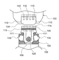
以下図面を用いて本発明の腕時計型機器を実施する最良の形態を説明する。図1は、本発明の腕時計型機器の構成を説明する概略図である。 図1において、100は腕時計型機器の機器本体、101は接続手段、102はバンド部材、103は第1の電気接点、104は舌部、105はバンド部材102の端部に設けるコネクタ部、106はコネクタ部105に設ける第2の電気接点である。107は導電性の配線、108は機器本体100に内蔵している電子回路、110はプッシュボタン、111は嵌合ツメ、112は嵌合穴である。140は表示手段である。接続手段101は、第1の電気接点103と舌部104と嵌合穴112を有している。
[Description of Configuration of Wristwatch Device of the Present Invention: FIG. 1]
The best mode for carrying out the wristwatch device of the present invention will be described below with reference to the drawings. FIG. 1 is a schematic diagram illustrating the configuration of a wristwatch-type device according to the present invention. In FIG. 1, 100 is a device body of a wristwatch type device, 101 is a connection means, 102 is a band member, 103 is a first electrical contact, 104 is a tongue portion, 105 is a connector portion provided at an end of the
バンド部材102は、例えば、ある程度の柔軟性を有する樹脂素材または金属でできている。予め円弧を描くように形成してもよく、樹脂素材に金属外装を装着する構成であってもよい。金属外装は、形状記憶合金で構成してもよい。
The
バンド部材102の内部には導電性の配線107を設けてあり、一端を機器本体100に設ける電子回路108と接続しており、他端をコネクタ部105に設ける第2の電気接点106に接続している。
A
バンド部材102の内部に設けた導電性の配線107は、例えば、アンテナ板とすることができる。機器本体100内に設ける電子回路108は、この場合は、この導電性の配線107に伝搬した外部からの信号を受信するための受信回路となる。
バンド部材102の材質を金属で構成する場合は、この導電性の配線107を外装に用いる金属と絶縁する。
The
When the
なお、図1に示す例では、説明しやすいように、導電性の配線107は1本のみ明示されているが、実際には必要な数だけ装備する。例えば、信号線や電源線、シールド用のGND線など、腕時計型機器に必要な配線を施すことができる。同様に、図1に示す例では、第1の電気接点103と第2の電気接点106とはそれぞれ4つ設けているが、それに限定するものではなく、必要な数だけ設けることができる。
また、これらの配線や電気接点、接続手段101の形状は、知られている規格の接続手段に合わせてもよい。例えば、USB(Universal Serial Bus)インターフェースである。このように、他の機器に用いられている接続形態とコンパチブルにしておくことで、本発明の腕時計型機器を他の多くの機器と接続させることができる。
In the example shown in FIG. 1, only one
Further, the shapes of these wirings, electrical contacts, and connection means 101 may be matched to known standard connection means. For example, a USB (Universal Serial Bus) interface. In this way, the wristwatch type device of the present invention can be connected to many other devices by being compatible with the connection mode used for other devices.
腕時計型機器を指針式の腕時計に見たてた場合、機器本体100の12時方向にバンド部材102が係止してあり、6時方向に接続手段101を設けている。
コネクタ部105は、6時方向から接続手段101に嵌合し、第1の電気接点103と第2の電気接点106とは接続する。
When the wristwatch-type device is viewed as a pointer-type wristwatch, the
The
このようなコネクタ部105と接続手段101との嵌合状態では、バンド部材102はリング状となって、使用者の人体(この場合は腕)を固定するのである。導電性の配線107がアンテナ板であるとすると、この状態では、アンテナ板は閉ループを形成することになる。
In such a fitting state between the
ところで、長波などの電波を受信し時刻を修正する、いわゆる電波式腕時計や電波を使って情報を受信する腕時計型ページャなどの腕時計型機器は、アンテナ板をバンド部材に収納したものがすでに提供されている。このような腕時計型機器は、12時側のバンド部材と6時側のバンド部材とにそれぞれ内蔵された2枚のアンテナ板をバンド部材に設けたバックルなどで接続する構成を有している。このような構成でないと、使用者の腕に固定できないからである。このような構成では、バックル部分のアンテナ板同士の接続部分で人体からの水分や脂分の浸入を許してしまうことが多いが、本発明の腕時計型機器では、バックルが必要ではないから、アンテナ板を劣化させることはないのである。 By the way, watch-type devices such as so-called radio-type wristwatches that receive radio waves such as long waves and correct the time, and watch-type pagers that receive information using radio waves, have already been provided with antenna plates housed in band members. ing. Such a wristwatch-type device has a configuration in which two antenna plates respectively built in the 12 o'clock side band member and the 6 o'clock side band member are connected by a buckle or the like provided on the band member. This is because it cannot be fixed to the user's arm without such a configuration. In such a configuration, the connection part between the antenna plates of the buckle part often allows intrusion of moisture and fat from the human body, but the wristwatch type device of the present invention does not require a buckle, so the antenna It does not degrade the plate.
コネクタ部105と接続手段101との接続は、嵌合ツメ111と嵌合穴112とが嵌合することでなされ、プッシュボタン110の押圧により、これらの接続が解除される。これについては、後述する。
The
バンド部材102と機器本体100との接続部分である接続手段101と人体との間には、舌部104がある。この舌部104のため、第1の電気接点103は、直接人体と触れることもなく、人体からの水分や脂分の接触による接点の腐食を防止することができる。
舌部104は、機器本体100と一体に設けることができる。もちろん、別体として設けて機器本体100に接続することもできる。機器本体100と一体に設ける場合は、例えば、機器本体100の裏蓋を延長して形成してもよい。いずれにしても、舌部104は、平面的に第1の電気接点103より大きく、そして電気接点と人体との間にあればよい。これは本発明の腕時計型機器の特徴的な部分である。
この舌部104は、コネクタ部105が接続手段101に嵌合した状態では、機器本体100の上面から見ることはできず、隠れてしまう。このようにすることによって、機器本体100のデザイン性を損ねることなく、第1の電気接点103を守ることができる。
A
The
The
表示手段140は、機器本体100の情報を表示するための手段である。内蔵する電子
回路108での演算結果や、外部機器から受信した情報を表示することができる。それらの演算結果や情報は、表示手段140の表示エリアに画像や文字やアイコン(絵文字)などとして表示することができる。
機器本体100には、図示しないが計時手段を有しており、表示手段140には、計時手段からの情報を用いて時刻を表示させることができる。図1に示す例では、10時38分を表す数字が表示してある。
The
Although not shown, the device
表示手段140は、液晶表示装置などを用いることが好ましい。その理由は、液晶表示装置が低消費電流に適しているからである。液晶表示装置は、メモリ性を有する液晶表示装置を用いてもよい。例えば、強誘電性液晶表示装置である。強誘電性液晶表示装置は、自発分極を持つ強誘電性液晶を用いており、これに電界を印加することで自発分極の向きを変え液晶分子の傾きを変えることができる。このため、電界を切った場合でもそれぞれの状態を保持し続ける。このようにメモリ性を持つので、表示を維持するための電力が必要なく、表示装置として大幅に低消費電力化とすることができる。
もちろん、表示手段140に、針式のアナログ時計と液晶表示装置とを用いてもよいことは、言うまでもない。
The display means 140 preferably uses a liquid crystal display device or the like. The reason is that the liquid crystal display device is suitable for low current consumption. As the liquid crystal display device, a liquid crystal display device having a memory property may be used. For example, a ferroelectric liquid crystal display device. The ferroelectric liquid crystal display device uses a ferroelectric liquid crystal having spontaneous polarization, and by applying an electric field to the ferroelectric liquid crystal, the direction of spontaneous polarization can be changed and the inclination of liquid crystal molecules can be changed. For this reason, even when the electric field is turned off, each state is kept. Since it has a memory property as described above, power for maintaining display is not required, and the power consumption of the display device can be significantly reduced.
Of course, it goes without saying that a hand type analog timepiece and a liquid crystal display device may be used for the display means 140.
なお、図1は、説明しやすいように機器本体100には、腕時計型機器を操作するために必要なスイッチやボタンは省略してある。
In FIG. 1, for ease of explanation, the device
[接続手段の説明:図2]
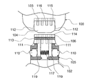
次に、本発明の腕時計型機器のコネクタ部105と接続手段101との嵌合状態を説明する。図2は接続手段101付近を拡大した図であって、コネクタ部105は説明しやすいようにその内部構造が見えるように記載している。
[Description of connection means: FIG. 2]
Next, the fitting state between the
図2において、109は嵌合バネ、113はコネクタ部105の側面、114はコネクタ部105の先端面、115は接続手段101の内壁、116は接続手段101の奥端面、120はバネガイドである。既に説明した同一の構成には同一の番号を付与している。
In FIG. 2, 109 is a fitting spring, 113 is a side surface of the
図2において、コネクタ部105は、プッシュボタン110と嵌合ツメ111とを有している。嵌合ツメ111は、弾性材料で作られた嵌合バネ109の両端に配置され、コネクタ部105の側面である側面113より突出する方向に付勢されている。
嵌合ツメ111は、コネクタ部105の先端面114の方向に傾斜が設けてある。プッシュボタン110を押し込むと嵌合ツメ111が側面113とほぼ同じかそれより引き込まれる。嵌合バネ109は、バネガイド120により位置決めされており、プッシュボタン110の押圧でも嵌合バネ109の位置がずれないようになっている。
In FIG. 2, the
The
次に、バンド部材102を機器本体100に接続する場合を説明する。
バンド部材102のコネクタ部105を機器本体100の接続手段101に向けて押し込む。コネクタ部105の側面113と接続手段101の内壁115とが当接して案内される。
嵌合ツメ111には傾斜が設けてあるから、この傾斜により嵌合ツメ111は、内壁115に当接したときに側面113方向に付勢される。この力によって、嵌合ツメ111は、嵌合バネ109の付勢力に抗って側面113とほぼ同じ面まで押される。
さらにバンド部材102を機器本体100の方向に押し込むと、コネクタ部105の先端面114と接続手段101の奥端面116とが当接する位置で止まる。この位置は、嵌合ツメ111と嵌合穴112とが一致する位置であって、嵌合ツメ111の先端は、内壁115に押されなくなるので、再び付勢力を取り戻し、嵌合穴112に嵌合する。
この状態で、接続手段101に備える第1の電気接点103とコネクタ部105に備える第2の電気接点106とが接続される。
Next, a case where the
The
Since the
When the
In this state, the first
嵌合ツメ111は、嵌合穴112に嵌合しているため、バンド部材102に力を印加してもバンド部材102と機器本体100とが外れることはない。
Since the
バンド部材102を機器本体100から開放する(外す)場合は、プッシュボタン110を押し込んで互いを離間する方向に引けばよい。プッシュボタン110の押し込みによって、嵌合ツメ111がコネクタ部105の側面113とほぼ同じかそれより引き込まれるので嵌合ツメ111と嵌合穴112との嵌合が解除されて、容易にバンド部材102を外すことができる。
In order to release (remove) the
[接続手段の説明:図3]
コネクタ部105の構造は、以上の説明の構成に限定するものではない。図3は、図2に示す構造とは異なる構造を説明するための図であって、図2に示す嵌合バネ109の代わりにコイルバネ117を用いて、図2に示すコネクタ部105と同等の機能を持たせた例を説明する図である。
嵌合ツメ111は、嵌合部材119の両端に配置され、コイルバネ117によりコネクタ部105の側面である側面113より突出する方向に付勢されている。なお、既に説明した同一の構成には同一の番号を付与している。
[Description of connection means: FIG. 3]
The structure of the
The
図3に示すように、プッシュボタン110を押し込むと、嵌合ツメ111は、コイルバネ117の付勢力に抗って側面113とほぼ同じかそれより引き込まれる。バンド部材102を機器本体100に接続する場合と開放する場合とについては、図2の例と同様であるので、説明は省略する。
As shown in FIG. 3, when the
[外部機器との接続の説明:図4]
本発明の腕時計型機器は、電波などを用いて導電性の配線107を介して外部からの信号を受信することができるが、機器本体100に直接外部からの信号を入力することもできる。
図4は、外部機器、例えば、パーソナルコンピュータなどと接続するための接続装置と機器本体100とを接続する例を説明するものである。
図4において、150は外部コネクタ、155はケーブル、160は外部機器との接続装置である。
[Description of connection with external device: Fig. 4]
The wristwatch-type device of the present invention can receive an external signal through the
FIG. 4 illustrates an example in which a connection apparatus for connecting to an external device such as a personal computer and the device
In FIG. 4, 150 is an external connector, 155 is a cable, and 160 is a connection device with an external device.
外部機器との接続装置160は、機器本体100と接続する場合、接続手段101またはコネクタ部105のどちらにも接続できる。本発明の腕時計型機器の接続形状に合わせて外部コネクタ150を用意すればよいのである。
外部機器との接続装置160は、外部コネクタ150を機器本体100と接続し、外部からの信号を第1の電気接点103または第2の電気接点106を介して伝達することができる。
外部からの信号とは、例えば、充電用の電気信号である。この電気信号を受信し、機器本体100に備える図示しない充電回路や二次電池に電力を蓄積することができる。
もちろん、外部からの信号は、これに限定するものではない。例えば、外部機器をパーソナルコンピュータとすれば、このパーソナルコンピュータで作成した電子情報なども機器本体100との間で送受信を行うこともできる。
The
The
The signal from the outside is, for example, an electric signal for charging. The electric signal can be received, and electric power can be stored in a charging circuit or a secondary battery (not shown) provided in the device
Of course, the signal from the outside is not limited to this. For example, if the external device is a personal computer, electronic information created by the personal computer can be transmitted to and received from the device
また、本発明の腕時計型機器は、機器本体100に備える接続手段101とバンド部材102に備えるコネクタ部105とで、各々異なる外部機器と接続することもできる。
例えば、図4を例にして説明すると、外部機器との接続装置160を接続手段101に接続し、他の外部機器との接続装置(図示せず)をコネクタ部105に接続するのである。
このようにすることにより、例えば、接続手段101側を外部機器との情報の送受信に用い、コネクタ部105側を外部機器からの充電用電圧信号の受信に用いることができる。
2つの異なる接続要素が互いに異なる外部機器と接続しうることで、情報や信号の送受に関する時間を短縮することができる。つまり、機器本体100を充電しながら情報を得ることができるのである。
The wristwatch type device of the present invention can also be connected to different external devices by the connecting means 101 provided in the device
For example, referring to FIG. 4, a
By doing in this way, for example, the connection means 101 side can be used for transmission / reception of information with an external device, and the
Since two different connection elements can be connected to different external devices, it is possible to reduce time related to transmission and reception of information and signals. That is, information can be obtained while charging the device
コネクタ部105と接続手段101との嵌合状態で、バンド部材102はリング状となるが、接続手段101に外部から接続装置を接続する場合においても、バンド部材102は、ある程度リング状の形状を維持しておけば、使用者の人体から本発明の腕時計型機器が脱落することはない。つまり、本発明の腕時計型機器は、使用者が人体に装着したまま外部機器との接続が可能であり、外部機器との接続のために人体から外さなければならないというわずらわしさがないのである。この点も本発明の腕時計型機器の特徴である。
The
以上の説明で明らかなように、本発明の腕時計型機器は、接続手段101に設ける舌部104のため、この部分への人体からの水分や脂分の浸入を遮蔽することができる。このため、接続手段101またはコネクタ部105、あるいは外部機器との接続装置160の内部の電気接点を保護することができる。
また、本発明の腕時計型機器の人体への装着または外部機器の接続装置との接続は、接続手段101とコネクタ部105との接続と開放とを必ず伴うため、仮に人体からの水分や脂分が舌部104を超えて接続手段101に進入したとしても、これらの接続と開放とにより、水分や脂分が同じ部分に留まることはなく、第1の電気接点103や第2の電気接点106などを腐食させることはないのである。
As is clear from the above description, the wristwatch-type device of the present invention can shield the intrusion of moisture and fat from the human body into this portion because of the
In addition, since the connection of the wristwatch type device of the present invention to the human body or the connection device of the external device is necessarily accompanied by the connection and release of the connection means 101 and the
本発明の腕時計型機器は、腕に装着する機器としてのデザイン性を損ねることなく人体から発生する水分や脂分の影響を受けずに腕時計型機器とバンド部材とを接続できる。したがって、常時人体に接続する電子機器に適用することができる。特に、腕時計型の小型電子機器や電波受信式腕時計や腕時計型ページャに好適である。 The wristwatch-type device of the present invention can connect the wristwatch-type device and the band member without being affected by moisture and fat generated from the human body without impairing the design as a device worn on the arm. Therefore, the present invention can be applied to electronic devices that are always connected to the human body. In particular, it is suitable for wristwatch-type small electronic devices, radio wave reception wristwatches and wristwatch-type pagers.
100 腕時計型機器の機器本体
101 接続手段
102 バンド部材
103 第1の電気接点
104 舌部
105 コネクタ部
106 第2の電気接点
107 導電性の配線
108 電子回路
109 嵌合バネ
110 プッシュボタン
111 嵌合ツメ
112 嵌合穴
113 側面
114 先端面
115 内壁
116 奥端面
117 コイルバネ
119 嵌合部材
120 バネガイド
150 外部コネクタ
155 ケーブル
160 接続装置
DESCRIPTION OF
Claims (3)
前記バンド部材の一端には、コネクタ部を備え、
前記バンド部材は、前記コネクタ部と前記接続手段とを接続することでリング状となり、人体の装着部位に固定可能となることを特徴とする腕時計型機器。 A wristwatch type information device having a connection means for connecting with other devices and including a band member,
One end of the band member is provided with a connector part,
The wristband device is characterized in that the band member is formed in a ring shape by connecting the connector portion and the connection means, and can be fixed to a wearing part of a human body.
前記バンド部材は、導電性の配線を有し、
前記コネクタ部は、前記導電性の配線と接続する第2の電気接点を有し、
前記コネクタ部と前記接続手段との接続によって、前記第1の電気接点と前記第2の電気接点とが接することを特徴とする請求項1に記載の腕時計型機器。 The connecting means has a first electrical contact for connecting to an internal electronic circuit,
The band member has conductive wiring,
The connector part has a second electrical contact to be connected to the conductive wiring,
The wristwatch-type device according to claim 1, wherein the first electrical contact and the second electrical contact are brought into contact with each other by connection between the connector portion and the connection means.
Priority Applications (2)
| Application Number | Priority Date | Filing Date | Title |
|---|---|---|---|
| JP2005273451A JP2007085821A (en) | 2005-09-21 | 2005-09-21 | Wrist watch type apparatus |
| US11/524,975 US20070064542A1 (en) | 2005-09-21 | 2006-09-21 | Wristwatch type apparatus |
Applications Claiming Priority (1)
| Application Number | Priority Date | Filing Date | Title |
|---|---|---|---|
| JP2005273451A JP2007085821A (en) | 2005-09-21 | 2005-09-21 | Wrist watch type apparatus |
Publications (2)
| Publication Number | Publication Date |
|---|---|
| JP2007085821A true JP2007085821A (en) | 2007-04-05 |
| JP2007085821A5 JP2007085821A5 (en) | 2008-10-02 |
Family
ID=37883901
Family Applications (1)
| Application Number | Title | Priority Date | Filing Date |
|---|---|---|---|
| JP2005273451A Pending JP2007085821A (en) | 2005-09-21 | 2005-09-21 | Wrist watch type apparatus |
Country Status (2)
| Country | Link |
|---|---|
| US (1) | US20070064542A1 (en) |
| JP (1) | JP2007085821A (en) |
Cited By (6)
| Publication number | Priority date | Publication date | Assignee | Title |
|---|---|---|---|---|
| KR101393388B1 (en) * | 2013-11-12 | 2014-05-13 | (주)대한특수금속 | Smart watch and connecting gender thereof |
| JP2014115288A (en) * | 2012-12-06 | 2014-06-26 | Eta Sa Manufacture Horlogere Suisse | Wrist watch having electric connector |
| JP2014171809A (en) * | 2013-03-12 | 2014-09-22 | Seiko Instruments Inc | Portable electronic device |
| KR20160048618A (en) * | 2015-03-06 | 2016-05-04 | (주)아바엔터테인먼트 | The removable body and the other watch band of watch-type mobile terminal |
| KR20160106410A (en) * | 2015-03-02 | 2016-09-12 | 삼성전자주식회사 | Electronic device with connection and operation method thereof |
| CN109687555A (en) * | 2019-01-30 | 2019-04-26 | 上海传英信息技术有限公司 | Motion bracelet charging unit and motion bracelet |
Families Citing this family (55)
| Publication number | Priority date | Publication date | Assignee | Title |
|---|---|---|---|---|
| EP1428450A1 (en) * | 2002-12-09 | 2004-06-16 | Rebecca Yeager | Wristwatch with elastic band comprising a single strand |
| WO2005083546A1 (en) * | 2004-02-27 | 2005-09-09 | Simon Richard Daniel | Wearable modular interface strap |
| US7607243B2 (en) | 2006-05-03 | 2009-10-27 | Nike, Inc. | Athletic or other performance sensing systems |
| US8326353B1 (en) * | 2007-06-27 | 2012-12-04 | ENORCOM Corporation | Customizable mobile device |
| US20090040877A1 (en) * | 2007-08-10 | 2009-02-12 | Game Time, Llc | Portable timepiece and alarm linked to scheduled events |
| JP5550077B2 (en) | 2007-09-07 | 2014-07-16 | ナイキ インターナショナル リミテッド | Wearable device assembly with motor functionality |
| CN102089042A (en) | 2008-04-02 | 2011-06-08 | 耐克国际有限公司 | Wearable device assembly having athletic functionality |
| EP2555676B1 (en) | 2010-02-05 | 2015-10-14 | Biovotion AG | Wearable sensor device |
| WO2011094876A1 (en) * | 2010-02-05 | 2011-08-11 | Solianis Holding Ag | Wearable sensor device with battery |
| US20120069511A1 (en) * | 2010-03-22 | 2012-03-22 | Azera Paule S | Data storage unit having clasping feature |
| US8029302B1 (en) * | 2010-06-17 | 2011-10-04 | Xingyi Duan | Strap with charging and data transmitting function |
| US20120315776A1 (en) * | 2011-06-08 | 2012-12-13 | Wei-Jia Liang | Connector assembly |
| US8279716B1 (en) | 2011-10-26 | 2012-10-02 | Google Inc. | Smart-watch including flip up display |
| US8467270B2 (en) * | 2011-10-26 | 2013-06-18 | Google Inc. | Smart-watch with user interface features |
| FR2985053B1 (en) * | 2011-12-22 | 2015-08-07 | Sagemcom Documents Sas | DEVICE FOR STORING AND EXCHANGING DATA |
| USD731898S1 (en) * | 2012-03-01 | 2015-06-16 | Movband, Llc | Wrist-worn electronic display |
| WO2013188412A1 (en) * | 2012-06-11 | 2013-12-19 | Sorias Yeoshua | Watch assembly with a spare battery for readily powering an external mobile electronic device |
| EP2813907B1 (en) * | 2013-06-11 | 2018-08-01 | LG Electronics, Inc. | Watch type mobile terminal |
| US20150097517A1 (en) * | 2013-10-09 | 2015-04-09 | Jeffrey James Stephenson | Battery strap for electronic device |
| TWI511682B (en) * | 2013-11-04 | 2015-12-11 | Sheng Hsin Liao | Portable modularized stack device |
| WO2015099809A1 (en) * | 2013-12-29 | 2015-07-02 | Bodhi Technology Ventures Llc | Electrical and mechanical connection mechanisms |
| US9274506B2 (en) * | 2014-01-29 | 2016-03-01 | Cheng Uei Precision Industry Co., Ltd. | Wearable electronic device |
| US9170612B2 (en) | 2014-02-21 | 2015-10-27 | Farshad Farjami | Wristband accessories for powering a wearable computer |
| US20150241912A1 (en) * | 2014-02-21 | 2015-08-27 | Farshad Farjami | Wristband Accessories For A Wearable Computer |
| USD751068S1 (en) * | 2014-03-07 | 2016-03-08 | Sony Mobile Communications Ab | Display portion of watch shaped communications equipment |
| FR3021128B1 (en) * | 2014-05-14 | 2017-10-20 | Kevin Oualli | BRACELET WATCH WITH CORNES AND BRACELET EXCHANGEABLE |
| TWM493182U (en) * | 2014-07-11 | 2015-01-01 | Molex Taiwan Ltd | Electrical connector and electronic device with electrical connector |
| US9445633B2 (en) | 2014-09-30 | 2016-09-20 | Apple Inc. | Portable electronic device connector |
| KR102245820B1 (en) * | 2014-11-04 | 2021-04-28 | 삼성전자주식회사 | Electronic Device having Flexible Cable |
| US10200087B2 (en) * | 2014-12-23 | 2019-02-05 | Intel Corporation | Wireless power receiving coil along a loop of a device |
| KR102329820B1 (en) * | 2015-01-29 | 2021-11-23 | 삼성전자주식회사 | Wearable type device |
| US9367087B1 (en) | 2015-03-03 | 2016-06-14 | Pebble Technology Corp. | Securing device for connecting to a display device |
| JP2016168289A (en) * | 2015-03-16 | 2016-09-23 | カシオ計算機株式会社 | Band and electronic equipment |
| EP3101508B1 (en) * | 2015-05-22 | 2020-04-08 | Lg Electronics Inc. | Wearable smart device |
| CN104821975B (en) * | 2015-05-25 | 2018-10-30 | 京东方科技集团股份有限公司 | A kind of flexible display apparatus and its pedestal |
| CN204790337U (en) * | 2015-05-27 | 2015-11-18 | 深圳市鼎芯东方科技有限公司 | Intelligent watch |
| US20160363957A1 (en) | 2015-06-09 | 2016-12-15 | Christian Stroetmann | Wearable computer with electronic strap and attachment therefor |
| KR20170038359A (en) * | 2015-09-30 | 2017-04-07 | 엘지이노텍 주식회사 | Sensor for wearing of wearable device and wearable device having the same |
| US9461386B1 (en) * | 2015-10-09 | 2016-10-04 | Pebble Technology, Corp. | Spring pin electrical connector |
| US20170179987A1 (en) * | 2015-12-18 | 2017-06-22 | Intel Corporation | Embedded port in wearable mobile electronic device |
| CN105768407A (en) * | 2016-05-24 | 2016-07-20 | 青岛歌尔声学科技有限公司 | Intelligent bracelet with rotatable watch body |
| KR20170140962A (en) * | 2016-06-14 | 2017-12-22 | 삼성전자주식회사 | Strap and Electronic device including the same |
| US10058148B1 (en) * | 2016-09-21 | 2018-08-28 | Apple Inc. | Attachment mechanism architectures for a watch band |
| US10058149B1 (en) * | 2016-09-21 | 2018-08-28 | Apple Inc. | Attachment mechanism architectures for a watch band |
| TWI622899B (en) * | 2016-09-30 | 2018-05-01 | 仁寶電腦工業股份有限公司 | Wearable device and modularized functional module thereof |
| CN106816693B (en) * | 2017-01-17 | 2020-01-03 | 青岛海信移动通信技术股份有限公司 | Antenna of intelligent wrist-worn device and intelligent wrist-worn device |
| CN107196161A (en) * | 2017-06-26 | 2017-09-22 | 恪道技术(深圳)有限公司 | A kind of portable data line |
| EP3432087B1 (en) * | 2017-07-21 | 2020-03-18 | ETA SA Manufacture Horlogère Suisse | Attachment device |
| US20190137947A1 (en) * | 2017-11-05 | 2019-05-09 | Karim Jean Yaghmour | Module-Driven Smartwatch |
| CN208463107U (en) * | 2018-04-09 | 2019-02-05 | 云谷(固安)科技有限公司 | Wrist equipment and its wrist strap component |
| US10809666B2 (en) * | 2018-05-22 | 2020-10-20 | Fitbit, Inc. | Low-profile band latch mechanism |
| US11287779B2 (en) * | 2018-08-09 | 2022-03-29 | Apple Inc. | Modular system for watch |
| EP3712719B1 (en) * | 2019-03-20 | 2021-11-10 | Renata AG | A wristwatch with battery integrated in the clasp |
| US11033082B1 (en) | 2020-04-14 | 2021-06-15 | Fitbit, Inc. | Wearable device straps and attachment hardware therefor |
| US20230393635A1 (en) * | 2022-06-06 | 2023-12-07 | Apple Inc. | Modular light assembly for a wearable device |
Citations (2)
| Publication number | Priority date | Publication date | Assignee | Title |
|---|---|---|---|---|
| JP2002360317A (en) * | 2001-06-07 | 2002-12-17 | Horon Create:Kk | Arm band with wearable general-purpose function |
| JP2004144536A (en) * | 2002-10-23 | 2004-05-20 | Casio Comput Co Ltd | Band attaching structure |
Family Cites Families (6)
| Publication number | Priority date | Publication date | Assignee | Title |
|---|---|---|---|---|
| US3973706A (en) * | 1974-12-30 | 1976-08-10 | Jacoby-Bender, Inc. | Connection from watchband-carried battery to electronic watch |
| US4769656A (en) * | 1987-01-28 | 1988-09-06 | Timex Corporation | Expansion band antenna for a wrist instrument and method of making it |
| EP0836717A4 (en) * | 1995-07-05 | 1998-10-14 | Motorola Inc | Conformal power supply |
| JP4042340B2 (en) * | 2000-05-17 | 2008-02-06 | カシオ計算機株式会社 | Information equipment |
| ATE399375T1 (en) * | 2002-10-28 | 2008-07-15 | Eta Sa Mft Horlogere Suisse | PORTABLE ELECTRONIC DEVICE HAVING AN ELECTRICAL CONNECTION IN THE DEVICE HOUSING |
| US7455525B2 (en) * | 2005-09-16 | 2008-11-25 | Imation Corp. | Continuous flexible band housing a memory device |
-
2005
- 2005-09-21 JP JP2005273451A patent/JP2007085821A/en active Pending
-
2006
- 2006-09-21 US US11/524,975 patent/US20070064542A1/en not_active Abandoned
Patent Citations (2)
| Publication number | Priority date | Publication date | Assignee | Title |
|---|---|---|---|---|
| JP2002360317A (en) * | 2001-06-07 | 2002-12-17 | Horon Create:Kk | Arm band with wearable general-purpose function |
| JP2004144536A (en) * | 2002-10-23 | 2004-05-20 | Casio Comput Co Ltd | Band attaching structure |
Cited By (8)
| Publication number | Priority date | Publication date | Assignee | Title |
|---|---|---|---|---|
| JP2014115288A (en) * | 2012-12-06 | 2014-06-26 | Eta Sa Manufacture Horlogere Suisse | Wrist watch having electric connector |
| JP2014171809A (en) * | 2013-03-12 | 2014-09-22 | Seiko Instruments Inc | Portable electronic device |
| KR101393388B1 (en) * | 2013-11-12 | 2014-05-13 | (주)대한특수금속 | Smart watch and connecting gender thereof |
| KR20160106410A (en) * | 2015-03-02 | 2016-09-12 | 삼성전자주식회사 | Electronic device with connection and operation method thereof |
| KR102356450B1 (en) * | 2015-03-02 | 2022-01-27 | 삼성전자주식회사 | Electronic device with connection and operation method thereof |
| KR20160048618A (en) * | 2015-03-06 | 2016-05-04 | (주)아바엔터테인먼트 | The removable body and the other watch band of watch-type mobile terminal |
| KR101646541B1 (en) | 2015-03-06 | 2016-08-08 | (주)아바엔터테인먼트 | The removable body and the other watch band of watch-type mobile terminal |
| CN109687555A (en) * | 2019-01-30 | 2019-04-26 | 上海传英信息技术有限公司 | Motion bracelet charging unit and motion bracelet |
Also Published As
| Publication number | Publication date |
|---|---|
| US20070064542A1 (en) | 2007-03-22 |
Similar Documents
| Publication | Publication Date | Title |
|---|---|---|
| JP2007085821A (en) | Wrist watch type apparatus | |
| JP5918201B2 (en) | Wristwatch with electrical connector | |
| US10620587B2 (en) | Band type electronic device and substrate arrangement method | |
| KR100330351B1 (en) | Wrist instrument and electronic apparatus | |
| US6914564B2 (en) | Watchband antenna | |
| KR102348027B1 (en) | Connection Module and electronic device including the same | |
| US6874931B2 (en) | Portable instrument with a wristband provided with electric connection means | |
| KR101529921B1 (en) | Wrist watch type mobile terminal | |
| KR20170037050A (en) | Watch type mobile terminal and wireless charging device | |
| KR101393388B1 (en) | Smart watch and connecting gender thereof | |
| KR20160012436A (en) | Wearable device | |
| JP2018155727A (en) | Input device and method for manufacturing the same | |
| KR20160032712A (en) | Electric Charger Cradle With USB Interface And Wearable Device Comprising The Same | |
| CN111443591B (en) | Clock and watch | |
| JP2009182621A (en) | Housing case for mobile terminal | |
| CN216019500U (en) | Intelligent watch | |
| US6233203B1 (en) | Electronic timepiece | |
| CN219286695U (en) | Electronic equipment and wearable equipment | |
| JP2010039039A (en) | Camera | |
| CN211741853U (en) | Multifunctional intelligent watch | |
| CN113872273A (en) | Power adapter and watch | |
| JP2005098990A (en) | Equipment attached to wrist | |
| KR20050004426A (en) | Strap having USB connector and electronic devices comprising the same | |
| TWI548970B (en) | Wearable electronic device and core module thereof | |
| KR20150080705A (en) | Watch type mobile terminal |
Legal Events
| Date | Code | Title | Description |
|---|---|---|---|
| A521 | Written amendment |
Free format text: JAPANESE INTERMEDIATE CODE: A523 Effective date: 20080820 |
|
| A621 | Written request for application examination |
Free format text: JAPANESE INTERMEDIATE CODE: A621 Effective date: 20080820 |
|
| RD03 | Notification of appointment of power of attorney |
Free format text: JAPANESE INTERMEDIATE CODE: A7423 Effective date: 20080820 |
|
| A977 | Report on retrieval |
Free format text: JAPANESE INTERMEDIATE CODE: A971007 Effective date: 20100922 |
|
| A131 | Notification of reasons for refusal |
Free format text: JAPANESE INTERMEDIATE CODE: A131 Effective date: 20101005 |
|
| A02 | Decision of refusal |
Free format text: JAPANESE INTERMEDIATE CODE: A02 Effective date: 20110405 |