EP3237828B1 - Mécanisme de sécurité pour arme à feu - Google Patents
Mécanisme de sécurité pour arme à feu Download PDFInfo
- Publication number
- EP3237828B1 EP3237828B1 EP15874369.0A EP15874369A EP3237828B1 EP 3237828 B1 EP3237828 B1 EP 3237828B1 EP 15874369 A EP15874369 A EP 15874369A EP 3237828 B1 EP3237828 B1 EP 3237828B1
- Authority
- EP
- European Patent Office
- Prior art keywords
- safety
- trigger
- shaft
- selector
- rotary cam
- Prior art date
- Legal status (The legal status is an assumption and is not a legal conclusion. Google has not performed a legal analysis and makes no representation as to the accuracy of the status listed.)
- Active
Links
Images


Classifications
-
- F—MECHANICAL ENGINEERING; LIGHTING; HEATING; WEAPONS; BLASTING
- F41—WEAPONS
- F41A—FUNCTIONAL FEATURES OR DETAILS COMMON TO BOTH SMALLARMS AND ORDNANCE, e.g. CANNONS; MOUNTINGS FOR SMALLARMS OR ORDNANCE
- F41A17/00—Safety arrangements, e.g. safeties
- F41A17/46—Trigger safeties, i.e. means for preventing trigger movement
-
- F—MECHANICAL ENGINEERING; LIGHTING; HEATING; WEAPONS; BLASTING
- F41—WEAPONS
- F41A—FUNCTIONAL FEATURES OR DETAILS COMMON TO BOTH SMALLARMS AND ORDNANCE, e.g. CANNONS; MOUNTINGS FOR SMALLARMS OR ORDNANCE
- F41A11/00—Assembly or disassembly features; Modular concepts; Articulated or collapsible guns
Definitions
- the present invention generally relates to firearms, and more particularly to a safety selector mechanism suitable for a bolt-action firearm such as a rifle.
- a safety selector that controls the firing mode so that it must be contained within the stock assembly or another component that can be separated from the receiver or action.
- Pistol grips as popularized by the AR-15 genre of rifles (adopted by the U.S. military as the M16 rifle) have been commonly used on other types of modern firearms; often on rifles that were not originally designed for pistol grips.
- the safety selector On bolt action rifles modified to add a pistol grip, the safety selector may be left in its original location typically alongside the back of the bolt or on top of the buttstock behind the bolt, which is not easily accessed when holding onto a pistol grip instead of cradling the stock.
- this top-mounted safety selector location is inconvenient.
- the safety selector On firearms like the AR-15, where all of the fire-control components are contained in the lower receiver, the safety selector remains in the same relative position and does not hinder disassembly. If the fire-control group of components is connected to the receiver or action, while the safety selector is attached or contained within another component, it may be difficult to separate these components without disassembling additional rifle parts. This is especially true for rotating safety selectors, like used in AR-15 type rifles, where the cross shaft of the safety interacts with or intersects part of the fire-control group to block the firing mechanism. Optimally, the safety mechanism and selector switch should be strategically located to minimize the number of components which need to be disassembled to access to the firearm's firing mechanism.
- US 2009/0188145 discloses a two-stage trigger apparatus for use with firearms including a trigger and a sear arm operatively coupled to the trigger.
- the sear arm detachably couples to a first catch of a hammer of the firearm.
- a disconnector is pivotally coupled relative to the sear arm and detachably couples to a second catch of the hammer.
- At least one trigger spring operatively couples to the sear arm to bias the sear arm to an initial position.
- the trigger pivots relative to the sear arm between a first travel stop and a second travel stop of the sear arm, where the first travel stop prevents the trigger from pivotally moving relative to the sear arm in a first direction and the second travel stop prevents the trigger from pivotally moving relative to the sear arm in a second direction opposite the first direction.
- the trigger pivots between the first travel stop and the second travel stop relative to the sear arm.
- a biasing element is disposed between the sear arm and the trigger to bias the trigger toward the first travel stop.
- the trigger spring exerts a greater force on the sear arm than the force exerted by the biasing element on the trigger.
- a firearm with as safety mechanism is provided as claimed in claim 1.
- a firearm according to the present disclosure includes a safety mechanism which allows the safety selector to be mounted in a removable stock component separate from the firing mechanism assembly mounted in a trigger housing, but can still be easily separated without additional disassembly of safety or fire-control components.
- the safety selector allows selection of a "safe" firing mode in which the firing mechanism is disabled and a "fire” firing mode in which the firing mechanism is enabled to discharge the firearm.
- the concept also prevents the stock component and trigger housing from being separated from the receiver unless the safety selector is in the "safe” position.
- the safety selector can be installed for either left or right hand operation.
- the present safety mechanism uses another separate component in the form of a safety shaft to interact directly with the trigger.
- the safety shaft still operated by the safety selector, is located forward of the trigger in one embodiment to selectively engage or disengage the trigger; the trigger's movement being arrested when engaged to disable the trigger-actuated firing mechanism.
- the safety selector is mounted rearward of the trigger on the lateral side of the firearm in the same convenient position as used on an AR-15 rifle.
- the physically separated safety shaft and safety selector are mechanically coupled via a mechanical linkage such that rotating the selector concomitantly rotates and operates the shaft.
- a pistol grip may be provided which takes advantage of the side-mounted safety selector.
- the present invention also relates to a trigger housing assembly as claimed in claim 11 11.
- a further object of the present invention is a method for operating a safety mechanism of a firearm as claimed in claim 14.
- any reference to direction or orientation is merely intended for convenience of description and is not intended in any way to limit the scope of the present invention.
- Relative terms such as “lower,” “upper,” “horizontal,” “vertical,”, “above,” “below,” “up,” “down,” “top” and “bottom” as well as derivative thereof (e.g., “horizontally,” “downwardly,” “upwardly,” etc.) should be construed to refer to the orientation as then described or as shown in the drawing under discussion. These relative terms are for convenience of description only and do not require that the apparatus be constructed or operated in a particular orientation.
- action is used herein in its conventional sense in the firearm art as meaning the mechanism that loads and ejects shells into/from the firearm and opens and closes the breech (i.e. the area in the receiver between an openable/closeable breech face on the front of the bolt and the rear face of the barrel chamber).
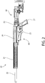
- FIGS. 1-4 depict a firearm 20 with safety selector and interlock mechanisms according to the present disclosure.
- the firearm 20 may be a bolt action rifle.
- firearm 20 generally includes a receiver 21, a trigger housing 22 detachably mounted to the receiver, a barrel 23 supported by the receiver, and optionally a handguard 24 enclosing and circumscribing at least part of the length of the barrel.
- the barrel includes an open front muzzle end 23a and an open rear breech end 23b (obscured beneath the handguard) coupled to the front end of the receiver 21 in any suitable manner (e.g. threading, interlocking lugs, barrel or lock nut, etc.).
- the barrel of rifle 20 defines a longitudinal axis LA and axial direction of the firearm coinciding with the centerline of the barrel 23 and its longitudinal bore formed therein between the muzzle and breech ends 23a, 23b (not shown) that defines the projectile pathway.
- Handguard 24 if provided may any type and coupled to the front end of the receiver and/or the barrel.
- Firearm 20 further includes a buttstock 30 extending rearward from the receiver 21 for placement against the user's shoulder when aiming the firearm held in a ready-to-fire position to acquire a target.
- Buttstock 30 may be any type or configuration of buttstock including fixed, adjustable and non-adjustable types, and folding and non-folding types. The invention is not limited by the type of buttstock which may be used.
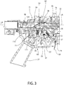
- Firearm 20 further includes a lower assembly or stock 60, which in one non-limiting embodiment is detachably mounted to the bottom of the receiver 21.
- Lower stock 60 includes a front portion 33, opposing rear portion 34, trigger guard 31 position to enclose trigger 28, a pistol grip 27 rearward of the trigger guard, and magazine well 29 forward of the trigger guard.
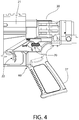
- the magazine well is configured and structured to removably detain and latch an insertable box type ammunition magazine via pivotable latch 32 mounted to the lower stock 60 at the rear of the magazine well 29 (best shown in FIG. 3 ).
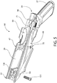
- a front mounting features includes an upwardly open locking recess 130 in lower stock 60 configured with a raised central rib.
- Recess 130 receives dual laterally spaced mounting lugs 132 projecting downwards from the front portion of receiver 21.
- One of the lugs 132 far or right lug
- one lug near or left side
- the lugs 132 are positioned on opposite sides of the raised rib central which is received between the lugs.
- the bottom of the lugs 132 may be convexly rounded and the recess 130 on opposite sides of the central rib may be concavely round by arcuate walls of the lower stock formed at the bottom of the recess (best shown in FIG. 5 ).
- the second rear mounting feature can be seen in FIGS. 3 and 5 .
- a socket head cap screw or other type threaded fastener 135 is inserted from the back of the firearm through the receiver 21 and lower stock 60.
- An axial threaded hole 98 formed in the rear of the lower stock receives the threaded fastener 135 extending through and from a concentrically aligned hole in the receiver which secures the rear end of the lower stock 60 to the receiver.
- this fastener 135 should be secured first, which helps brings the lower into a more consistent position and alignment relative to the receiver 21 and trigger housing 22, and afterwards the front bolt 131 may next be tightened lastly.
- the front bolt may be secured first before the rear bolt.
- the receiver 21 supports portions of the trigger-actuated fire control mechanism operable to discharge the firearm 20.
- the fire control mechanism includes an axially movable and elongated bolt 25 which may include a bolt handle 25a for manually operating the action to form a closed or open breech in relation to the chamber formed at the rear breech end 25b of barrel 25 which holds an ammunition cartridge.
- the bolt 25 is slidably moveable forward/rearward in an axially extending internal cavity 21a of receiver 21.
- the bolt assembly comprises a slidable striker or firing pin 26 carrier inside the bolt 25 for detonating a chambered cartridge when the firearm is discharged, a main spring 35 which acts to bias the firing pin rearward in a cocked ready-to-fire position, and a cocking piece 36 attached to the rear end of the firing pin (best shown in FIG. 3 ).
- the foregoing firing mechanism components are mounted in and supported by the receiver 21.
- the trigger housing 22 supports the other portions of the firing mechanism which operate together via pulling trigger 28 to release a cocked firing pin 26 for discharging the firearm.
- the trigger housing 22 has a generally rectangular elongated body defining an interior space 90 and various external openings to access the space for housing various firing mechanism components described herein.
- Trigger housing 22 may be removably attached to the receiver 21 by a variety of mechanical means.
- the trigger housing may include a plurality of laterally extending tabs 91 which interlock with mating tabs formed in the underside of the receiver (not shown) to suspend the housing from beneath the receiver.
- One or more fastener openings 92 may be provided which receive fasteners therethrough to complete securement of the trigger housing 22 to the receiver 21.
- fasteners alone may be used to secure the trigger housing to receiver.
- Other mechanical methods or combinations of methods may also be used.
- the invention is not limited by the type of means used to detachably secure the trigger housing to the receiver.
- the trigger housing 22 is securely attached to the receiver 21 of the firearm to ensure that the relationship between the sear 38 and the firing pin cocking piece 36 used to hold or release the firing pin 26 is maintained to prevent variable trigger feel and uncontrolled disengagement.
- the trigger housing 22 cannot be removed without first removing the lower stock 60 assembly from the firearm.
- the firing mechanism components supported by the trigger housing 22 includes a dual trigger mechanism including trigger 28 and trigger release member 37 which cooperates with the trigger to release a sear 38.
- Trigger 28 is movably mounted to trigger housing 22.
- the trigger is pivotably mounted to the module about transverse pin 56 which defines a pivot axis of the trigger.
- the trigger release member 37 is pivotably mounted to the trigger 28 about a second transverse pin 40 which is disposed just rearward of the trigger pin 40. This defines a separate pivot axis for the release member which is parallel to the trigger's pivot axis.
- Both the trigger 28 and the trigger release member 37 pivot in forward and rearward axial directions parallel to the longitudinal axis LA, as further described herein.
- Trigger 28 has a vertically elongated body including a lower arcuately curved operating end 43 for engaging a user's trigger finger and a vertically elongated upper sear catch protrusion 44 protruding upwards from the operating end.
- Lateral mounting hole 46 receives transverse pin 56 to pivotably mount the trigger to the trigger housing 22.
- Sear catch protrusion 44 includes an upward facing ledge 48 configured and arranged to selectively engage a mating downward facing hook-shaped sear catch 49 formed on the sear 38 for holding the sear in an upright position until the firearm 20 is discharged.
- the trigger release member 37 has a vertically elongated flat or plate-like elongate body defining an arcuately curved lower operating end 42 shaped for engaging a user's trigger finger and upper extension 41 protruding upwardly from the operating end. Lateral mounting hole 47 in the release member and mounting hole 61 in the trigger 28 receive transverse pin 40 to pivotably mount the release member to the trigger 28.
- the release member 37 is therefore supported by and movable in relation to the trigger.
- the operating end 42 of release member 37 is slideably received through a vertical slot 45 in curved operating end 43 of the trigger 28.
- Sear 38 has a horizontally elongated body including catch 49 formed on the front side or face, and an upwardly extending and vertically elongated firing pin catch protrusion 50.
- Lateral mounting hole 53 receives transverse pin 54 to pivotably mount the sear 38 to the trigger housing 22.
- Firing pin catch protrusion 50 defines a rear facing blocking surface 51 which is configured and arranged to abuttingly engage a mating front facing stop surface 52 formed on the cocking piece 36 of the bolt assembly (see, e.g. FIG. 3 ).
- Sear spring 39 biases the sear 38 into an upwards blocking position about pin 54 to force and positively maintain blocking surface 51 against stop surface 52 to prevent the release of the firing pin absent a trigger pull.
- spring 39 may be a helical compression spring; however, other types of springs (e.g. torsion) may be used.
- Trigger 28 in turn is biased into an upwards position about pin 56 by trigger spring 55.
- spring 55 may be a helical compression spring; however, other types of springs (e.g. torsion) may be used.
- Spring 55 acts on the vertical front side or surface 66 of the sear catch protrusion 44 of trigger 28 at a point above pin 56. This biases the trigger rearwards towards sear 38 which is mounted behind the sear catch protrusion 44 in the trigger housing 22. This in turn also forces the ledge 48 into positive engagement with the sear catch 49 on sear 38 for holding the sear in the upwards blocking position with a cocked firing pin 26.
- Spring 55 may be obliquely arranged to the longitudinal axis LA of firearm 20 to provide a line of action (extending along the axial centerline of the spring between its ends) which intersects the sear. This provides positive engagement of the ledge 48 on the trigger sear catch protrusion 44 with the sear catch 49.
- the sear catch protrusion 44 of trigger 28 is pivotable forwards about pin 56 to disengage and release the firing pin 26, as further described herein.
- a spring 57 is disposed between and has opposing ends which act against both the trigger 28 and trigger release member 37, as seen in FIG. 3 .
- the spring 57 is located above transverse pins 40 and 56 to bias the upper portions of the trigger and trigger release member apart. This in turn biases the curved lower operating end 42 of the trigger release member 37 to protrude forward beyond the curved lower operating end 43 of trigger 28 to maintain the release member. It bears noting that spring 57 is typically smaller in size than and has a lower spring force than trigger spring 55 so that the rearward spring force of spring 55 dominates and maintains positive engagement between the sear catch protrusion 44 and firing pin 26.
- the firearm 20 may be discharged in the following manner.
- the firing mechanism is shown in a ready-to-fire position.
- the bolt 25 is forward in a closed breech position in battery with the barrel 23 wherein a cartridge is chambered in the breech end 23b.
- Firing pin 26 is held rearward in a cocked position by sear 38 via engagement between blocking and stop surfaces 51, 52 of the sear and cocking piece 36 of the bolt respectively.
- the sear 38 is in the upwards blocking position being held there by the trigger release member 37 which similarly is in its upwards blocking position by spring 55.
- Trigger 28 is in a substantially vertical non-pulled position.
- a user To discharge the firearm, a user first pulls the exposed portions of the trigger 28 (via lower operating end 43) and trigger release member 37 (via lower operating end 42) rearward. It should be noted that the user initially engages the lower operating end 42 of the trigger release member 37 which protrudes forward of the trigger 28 in the normal un-pulled position (see, e.g. FIGS. 3 , 7 , and 8 ). The trigger release member moves rearward compressing spring 57 against the sear catch protrusion 44 which remains stationary at this stage until the front of operating end 42 of the trigger release member 37 is flush with the front of the operating end 43 of the trigger 28. It bears noting that trigger block pin 132 (see, e.g. FIG. 10B ) blocks the trigger movement until the trigger release is moved.
- a mechanical safety mechanism which acts to selectively arrest and disable the foregoing firing mechanism. This is intended to prevent inadvertent discharge of the firearm even if a trigger pull is attempted while the safety is "on.”
- the present safety mechanism provides for a bolt action rifle the convenience of a side-mounted AR-15 style safety selector with pistol grip both traditionally found only on conventional AR-15 semi-automatic action type rifles.
- a safety mechanism in one embodiment generally comprises a safety shaft 80, a safety selector 70, and a safety operating linkage such as control rod 100 operably coupling the shaft and selector together.
- the control rod operates and controls the position of the safety shaft 80 via rotating the safety selector 70, as further described herein. Both the safety shaft and safety selector are mounted to the trigger housing 22.
- the control rod 100 may a wire-form linkage to allow actuation of the safety shaft 80 from a different location or even a different amount of rotation.
- the safety shaft 80 in the illustrated embodiment is disposed forward of trigger 28 and the safety selector 70 is disposed rearward of the trigger in the trigger housing.
- This linkage system allows the safety selector position to be less critical because it is not directly contacting the trigger to arrest its movement. This is important because when the safety selector is connected to a different component than the trigger housing, very tight tolerances would be required to maintain a close relative position.
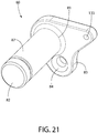
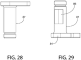
- the safety shaft 80 extends transversely through the trigger housing 22 between right and left opposing lateral sides 64, 65 of the housing and defines a pivot axis.
- the shaft has a generally cylindrical shape and includes opposing ends 81, 82.
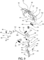
- a diametrically enlarged operating protrusion 83 extends radially from a first end 81 of the safety shaft in a direction perpendicular to the length of the shaft for coupling to the control rod 100.
- protrusion 83 may have an oblong or lobed shape as illustrated.
- An aperture 84 is formed in protrusion 83 which receives a first hook-shaped curved end 101 of control rod 100 (see also FIGS. 8 and 9 ).
- Spring 85 may be a torsion spring in one embodiment and biases the safety shaft 80 into two rotational positions shown in FIGS. 10A and 11A .
- One end of spring 85 engages the trigger housing as shown and the other end engages hole 133 formed in protrusion 83 (see, e.g. FIG. 21 ).
- Spring 85 helps stabilize rotational motion of the safety shaft.
- Other types of springs may be used in other embodiments.
- Safety shaft 80 is rotatable between a blocking position in which the safety shaft disables the firing mechanism and an unblocking position in which the shaft enables the firing mechanism to discharge the firearm.
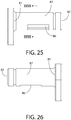
- Safety shaft 80 comprises a substantially flat operating surface 86 and a circumferentially adjoining arcuate blocking surface 87 formed by full diameter portions of the shaft on either side of the flat.
- the flat operating surface 86 is rotatable in radial position with the safety shaft.
- substantially flat indicates that although the operating surface 86 may be considered flat with respect to the arcuate blocking surface 87, the operating surface may in fact have a compound shape with portions of the surface 86 varying slightly in angularity to other portions of the surface 86 such as by 10 degrees or less; however, the overall profile of the operating surface may still be considered flat.
- the "flatness" of the surface will be dictated in part by configuration of the trigger 28 as explained below.
- the flat operating surface 86 is rotatable to a position arranged approximately parallel to a front surface 66 of the trigger 28 when the safety shaft is in the unblocking position. This provides a horizontal gap or clearance between the front surface 66 and flat operating surface 86 which allows pivotable movement of the trigger 28 sufficient to release the sear 38 and discharge the firearm by disengaging the cocking piece 36 of the firing pin 26. This corresponds to the rotational "fire" position of the safety selector 70.
- the safety shaft 80 is rotated to engage the arcuate blocking surface 87 with the front surface 66 of the trigger 28 when the safety shaft is in the blocking position. This prevents pivotable movement of the trigger sufficient to release the sear 38 and discharge the firearm. Movement of the trigger-actuated firing mechanism to discharge the firearm is therefore arrested. This corresponds to the rotational "safe" position of the safety selector 70.
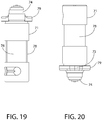
- the safety selector 70 comprises a cylindrical control shaft 71 which extends transversely through the trigger housing 22 between the right and left opposing lateral sides 64, 65 of the housing when positioned therein.
- the control shaft 71 defines opposing ends 72 and 73, and a pivot axis of the safety selector 70.
- the pivot axis of the safety selector 70 is located lower in trigger housing 22 than the pivot axis of the safety shaft 80.
- An elongated selector switch 74 is disposed on a first end 73 of the shaft for operating the safety selector via a user's finger or thumb.
- the selector switch 74 extends radially in a direction perpendicular to the length of the control shaft 71 and may have any suitable shape and a surface texture selected to facilitate grasping by a user in some embodiments (e.g. ridges, knurling, etc.).
- the selector switch 74 may further comprise a firing mode indicator 79 adjoining end 73 of the control shaft 71.
- the indicator 79 may be circular in one embodiment and have a diameter the same as, or in a preferred embodiment larger than the diameter of the adjoining control shaft.
- An arrow 75 may be formed on the firing mode indicator 79 which is rotatable to point to indicia comprising for example "safe” and "fire” which optionally may be engraved in or otherwise marked on the lower stock 60 (e.g. lateral side 68) adjacent to the indicator. Other firing modes and indicia may be provided.
- the safety selector 70 is mounted in the lower stock 60 and supported independently of the trigger housing 22 such that removal of the lower stock from the firearm 20 and receiver 21 removes the safety selector with the lower stock without removing the safety selector from the lower stock or disassembling the safety or firing mechanism components.
- FIG. 5 shows this arrangement in the lower stock 60 with the control shaft 71 extending transversely and being received through apertures in opposing lateral right and left sides 67, 68 of the stock.
- the end 72 of the control shaft 71 opposite the selector switch 74 penetrates lateral side 67 of the lower stock 60 and is exposed for viewing by the user. End 72 may be provided with firing mode indicia 77 (e.g.
- the lateral sides 67, 68 of the lower stock 60 are spaced apart defining an axially elongated internal cavity 69 which is upwardly open to receive the trigger housing 22 therein when the lower stock is attached to the receiver 21.
- the safety selector 70 is held in place by the trigger housing, and not with a spring and plunger like the selector in an AR-15 rifle. Not only does this eliminate parts, but it makes it possible to reverse a standard AR-15 selector to provide the same function with the safety lever on either the left or right side. Eliminating the drag from the spring loaded plunger also allows the safety to rotate more smoothly and reduce the likely hood of the selector coming to rest in a partially engaged or disengaged position.
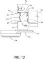
- FIGS. 12 and 13 are referenced now to describe this interface between the safety selector 70 and trigger housing 22.
- the control shaft 71 of the safety selector 70 may have a stepped configuration defining a reduced diameter central portion formed by spaced apart shoulders on shaft.
- a pair of inward facing and opposing abutment surfaces 96 is formed by the stepped shaft 71. Abutment surfaces 96 abuttingly engages mating outward facing abutment surfaces 97 formed on each side of the vertical slot 103 in the housing.
- the safety selector control shaft 71 can only be downwardly withdrawn from the slot 103 in the trigger housing 22, and not laterally removed therefrom.
- the safety selector 70 can be removed from the lower stock just be sliding it laterally outwards. While installed on the receiver 21, however, the trigger housing 22 prevents the selector from sliding laterally out of the stock or trigger housing. If an ambidextrous style selector is used, with a lever or switch 74 on each side which may be provided in some implementations, it would first have to be disassembled for removal from the lower assembly.
- the control shaft 71 of the safety selector 70 further comprises a flat surface 76 and a circumferentially adjoining arcuate surface 78 formed on either side of the flat in the reduced diameter central portion of the shaft.
- the flat surface 76 is rotatable in position with rotation of the safety selector control shaft 71 via the selector switch 74.
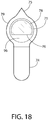
- the portion of the control shaft 71 including the flat surface 76 may have a generally semi-circular shape in transverse cross section, as illustrated in FIG. 18 . This shape lockingly mates with a complementary configured downwardly open vertical slot 111 formed in a rotary cam 110.
- rotary cam 110 cooperates with the safety selector 70 and control rod 100 to impart rotational movement to the safety shaft 80 which is inaccessible to a user when the lower stock 60 is attached to the receiver 21.
- the rotary cam operates to convert rotary motion of the selector switch 74 and control shaft 71 coupled thereto into substantially linear axial motion of the control rod 100 which moves the safety shaft 80 between the blocking and unblocking positions by rotating the safety selector 70.
- this permits placement of the safety selector 70 rear of the trigger 28 on the left lateral side 68 of the lower stock for convenient use with pistol grip 27 formed on the lower stock.
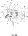
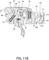
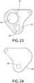
- the rotary cam 110 is mounted in an upwardly open recess 112 formed near the rear end 105 of the trigger housing 22 (see, e.g. FIGS. 8 , 10B , 11B ).
- the safety shaft 80 is disposed near the front end 104 of the housing 22.
- Recess 112 has an axial width which is slightly but not overly larger than the diameter of the rotary cam body to allow the cam to be inserted downwards into the recess when the safety mechanism components are installed in the trigger housing 22.
- the recess 112 may have a U-shape in transverse cross section and circumscribes a downwardly open vertical slot 103 formed in the trigger housing 22.
- the slot 103 may extend transversely through both the right and left lateral sides 64, 65 of the housing.
- the lower portions of the recess 112 on each side of the slot 103 in trigger housing 22 are bounded by bottom arcuate walls 95 which complement and engage the circular shape of the body of the rotary cam 110 on each side of slot 111.
- the rotary cam 110 is seated and rotatable on the arcuate walls 95 when fully installed in the trigger housing.
- the lower end of the recess 112 is smaller than the diameter of the rotary cam 110 so that the cam cannot fall through the vertical slot 103 in the trigger housing 22.
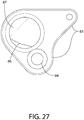
- Rotary cam 110 has a generally flat disk-like shape which is substantially but not perfectly circular in one embodiment as shown. In other embodiments, the shape may be perfectly circular.
- Rotary cam 110 has a downwardly open vertical slot 111 for upwardly receiving the safety selector control shaft 71 and an aperture 113 which receives a second hook-shaped curved end 102 of control rod 100 which is coupled thereto. Access through the trigger housing 22 for end 102 of the control rod to engage the aperture 113 of the rotary cam 110 may be provided through an arcuate slot 114 formed in the left lateral side 65 of the housing. The arcuate slot 114 is located to follow the arcuate path of the curved end 102 of the control rod 100 as the safety selector 70 is rotated.
- the control shaft 71 of the safety selector 70 is removably received in both of the mating downwardly open slots 103, 111 disposed in the trigger housing 22 and the rotary cam 110, respectively.
- Slots 103 and 111 may have similar heights and axial widths which complement and are preferably slightly larger than the diameter of the safety selector control shaft 71 sufficient to allow both insertion and rotation of the shaft when positioned therein.
- Slot 111 of the rotary cam 110 has an open bottom end and a closed top end with a shape complementary to the shape semi-circular shape of the portion of the control shaft 71 containing the flat surface 76. Accordingly, the top end of slot 111 has a mating flat surface 93 and arcuate surface 94 (see, e.g. FIGS. 9 , 10B , 11B ). This provides a relatively tight interlocking fit and engagement between the control shaft 71 and rotary cam 110 such that rotating the shaft 71 concomitantly rotates the rotary cam.
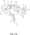
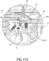
- Safety selector 70 is first assumed to be in the downward "fire" position shown in FIGS. 11A-C .
- the selector switch 74 is thus oriented obliquely to the longitudinal axis LA. In one embodiment, the selector switch 74 may be disposed at approximately 45 degrees to the longitudinal axis.
- the rotary cam 110 is oriented so that the lower rear quadrant obstructs the vertical slot 103 of the trigger housing 22.
- the rear curved end 102 of the control rod 100 is positioned at the rear of arcuate slot 114.
- the safety shaft 80 is in the unblocking position with the flat operating surface 86 of the positioned parallel to and facing the front surface 66 of the trigger 28. When the trigger is pulled, there is sufficient clearance between the safety selector 70 and front surface 66 of trigger 28 to allow the trigger sear catch protrusion 44 to move and release the sear 38 and firing pin 26 for discharging the firearm.
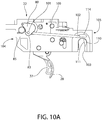
- the user moves and rotates the selector switch 74 upwards (counter-clockwise) to the horizontal "safe" position parallel to longitudinal axis LA as shown in FIGS. 10A-C .
- the rotary motion of the safety selector 70 moves or translates the control rod 100 axially forward.
- the curved end 102 of the control rod moves forward in turn to the front of the arcuate slot 114.
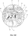
- the rotary cam 110 rotates counter-clockwise with the safety selector control shaft 71 such that the vertical slot 111 of the cam becomes vertically aligned with and approximately parallel to slot 103 of trigger housing 22. This would allow removal of the lower stock 60 from the receiver 21 if the firearm 20 were to be disassembled at this point, as already explained herein.
- the vertical slot 111 of the rotary cam 110 is rotatable in orientation with respect to the vertical slot 103 of the trigger housing 22 which remains stationary and fixed in position when mounted to the receiver 21.
- relative rotation between the rotary cam 110 and trigger housing 22 advantageously forms an interlock mechanism which prevents removal of the lower housing 60 from the receiver 21 when the safety selector 70 is in the "fire" position.
- the safety selector control shaft 71 is captured by the rotary cam 110 and the trigger housing 22, thereby preventing the lower assembly from being removed. While a firearm should always be unloaded before disassembly as dictated by responsible handling procedures, this mechanism is beneficial in that it ensures the safety of the firearm is engaged before the lower stock 60 can be removed and the trigger assembly is exposed. It also prevents the firearm from being re-assembled with the safety in the fire position.
- the vertical slots 103, 111 of the trigger housing 22 and rotary cam 110 are vertically aligned and fully open to at least the full diameter of the control shaft 71 of the safety selector. This allows the control shaft and safety selector 70 to be withdrawn downwards and removed from the slots 103, 111 with the lower stock 60 (in which the safety selector is rotatably mounted as shown in FIG. 4 ) to exposed the trigger housing 22 and trigger mechanism. Conversely when the safety selector 70 is in the "fire" position shown in FIGS.
- the vertical slots 103, 111 of the trigger housing 22 and rotary cam 110 are no longer vertically aligned and fully open to at least the full diameter of the control shaft 71 of the safety selector.
- the lower rear quadrant of the rotary cam now protrudes partially into and obstructs the slot 103 of the trigger housing 22 by a sufficient amount to prevent the control shaft 71 from passing downwards therethrough.
- Rotary cam slot 111 is no longer vertically aligned with but rather obliquely orientated to slot 103 of the trigger housing which traps the control shaft 71 of the safety selector 70 in the cam. This prevents the control shaft and safety selector 70 from being withdrawn downwards and removed from the slots 103, 111 when in the "fire" position so that the lower stock 60 cannot now be detached from the receiver 21, thereby forming an interlock mechanism.
Landscapes
- Engineering & Computer Science (AREA)
- General Engineering & Computer Science (AREA)
- Aiming, Guidance, Guns With A Light Source, Armor, Camouflage, And Targets (AREA)
Claims (15)
- Arme à feu (20) avec mécanisme de sécurité, l'arme à feu comprenant :une carcasse (21) ;un canon (23) couplé à la carcasse (21) et définissant un axe longitudinal (LA) ;un logement de gâchette (22) couplé, de manière détachable, à la carcasse (21) ;un mécanisme de tir actionné par gâchette monté dans le logement de gâchette (22) et opérationnel pour décharger l'arme à feu (20) en tirant sur la gâchette (28) ;un arbre de sécurité (80) s'étendant de manière transversale à travers le logement de gâchette (22) et définissant un premier axe de pivot, l'arbre de sécurité pouvant tourner entre une position de blocage dans laquelle l'arbre de sécurité désactive le mécanisme de tir et une position de déblocage dans laquelle l'arbre permet au mécanisme de tir de décharger l'arme à feu ;un sélecteur de sécurité (70) comprenant un arbre de commande (71) s'étendant transversalement à travers le logement de gâchette et définissant un second axe de pivot, le sélecteur de sécurité (70) couplé mécaniquement à l'arbre de sécurité (80) par une tige de commande (100) axialement allongée, de sorte que la rotation du sélecteur de sécurité (70) fait tourner l'arbre de sécurité (80), le sélecteur de sécurité (70) pouvant tourner entre une position de sécurité et une position de tir ; etle sélecteur de sécurité (70) comprenant en outre un commutateur de sélecteur (74) disposé sur et s'étendant radialement vers l'extérieur à partir d'une première extrémité de l'arbre de commande pour faire tourner le sélecteur de sécurité ;dans laquelle la rotation du sélecteur de sécurité (70) autour du second pivot dans une première direction de la position de sécurité à la position de tir fait tourner l'arbre de sécurité (80) autour du premier axe de pivot de la position de blocage à la position de déblocage ; etdans laquelle la rotation du sélecteur de sécurité (70) autour du second axe de pivot dans une seconde direction de la position de tir à la position de sécurité fait tourner l'arbre de sécurité (80) autour du premier axe de pivot de la position de déblocage à la position de blocage ;l'arme à feu comprenant en outre une came rotative (110) montée en rotation dans le logement de gâchette (22), la came rotative étant mise en prise, par verrouillage, par l'arbre de commande (71) du sélecteur de sécurité (70) ;dans laquelle la came rotative (110) convertit le mouvement de rotation du commutateur de sélecteur (74) en mouvement linéaire de la tige de commande (100) qui déplace l'arbre de sécurité (80) entre les positions de blocage et de déblocage en faisant tourner le sélecteur de sécurité (70) ;l'arbre de commande (71) du sélecteur de sécurité (70) est reçu de manière amovible par des fentes de couplage ouvertes vers le bas (103, 111) disposées dans le logement de gâchette (22) et la came rotative (110) ;dans laquelle lorsque la came rotative (110) est dans une première position de rotation, la fente (111) dans la came rotative est en alignement parallèle avec la fente (103) dans le logement de gâchette (22) afin de former une trajectoire de retrait verticale qui permet le retrait vers le bas de l'arbre de commande (71) et du sélecteur de sécurité (70) du logement de gâchette ; etdans laquelle lorsque la came rotative est dans une seconde position de rotation, la fente (111) dans la came rotative (110) est agencée de manière oblique sur la fente (103) dans le logement de gâchette (22) de sorte que la came rotative obstrue la trajectoire de retrait verticale qui empêche le retrait vers le bas de l'arbre de commande (71) et du sélecteur de sécurité (70) du logement de gâchette ; etune plaquette inférieure (60) montée de manière détachable sur la carcasse (21) ;le sélecteur de sécurité (70) monté de manière transversale dans la plaquette inférieure (60) et supporté en rotation indépendamment du logement de gâchette (22) de sorte que le retrait de la plaquette inférieure retire le sélecteur de sécurité avec cette dernière.
- Arme à feu selon la revendication 1, dans laquelle l'arbre de sécurité (80) comprend en outre une saillie opérationnelle oblongue (83) s'étendant radialement à partir d'une première extrémité de l'arbre de sécurité, une première extrémité de la tige de commande (100) étant couplée à la saillie opérationnelle et une seconde extrémité de la tige de commande étant couplée à la came rotative (110).
- Arme à feu selon la revendication 2, dans laquelle l'arbre de sécurité (80) est positionné vers l'avant de la gâchette (28) et le sélecteur de sécurité (70) est positionné vers l'arrière de la gâchette.
- Arme à feu selon la revendication 1, dans laquelle l'arbre de sécurité (80) met directement en prise la gâchette (28) pour empêcher son mouvement de pivotement lorsque l'arbre de sécurité est dans la position de blocage.
- Arme à feu selon la revendication 3, dans laquelle :l'arbre de sécurité (80) comprend une surface opérationnelle (86) sensiblement plate et une surface de blocage arquée (87) circonférentielle attenante,la surface opérationnelle (86) étant agencée parallèlement à un côté avant de la gâchette (28) lorsque l'arbre de sécurité (80) est dans la position de déblocage pour fournir le jeu qui permet le mouvement de pivot de la gâchette pour décharger l'arme à feu ; etla surface de blocage arquée (87) met en prise le côté avant de la gâchette (28) lorsque l'arbre de sécurité (80) est dans la position de blocage pour empêcher le mouvement de pivot de la gâchette.
- Arme à feu selon la revendication 1, dans laquelle l'arbre de commande (71) du sélecteur de sécurité (70) s'étend en outre transversalement à travers la plaquette inférieure (60) entre des premier et second côtés latéraux opposés, le commutateur de sélecteur (74) étant positionné à l'extérieur du premier côté latéral de la plaquette inférieure pour l'accès opérationnel ; et dans laquelle une seconde extrémité de l'arbre de commande opposée au commutateur de sélecteur s'étend à travers le second côté latéral et est exposée à la vue.
- Arme à feu selon la revendication 1, dans laquelle l'arbre de commande (71) du sélecteur de sécurité (70) comprend des surfaces de butée (96) opposées agencées pour mettre en prise des surfaces de butée de couplage (97) formées sur le logement de gâchette (22), les surfaces de butée sur le sélecteur de sécurité et le logement de gâchette agissant de concert pour empêcher le retrait latéral du sélecteur de sécurité du logement de gâchette.
- Arme à feu selon la revendication 1, comprenant en outre :un boulon (25) actionné manuellement axialement mobile vers l'avant et vers l'arrière dans la carcasse (21), le boulon comprenant un percuteur à ressort (26) et une pièce d'armement (36) couplée au percuteur ;un levier d'armement (38) mis en prise de manière pivotante entre la gâchette (28) et la pièce d'armement (36), le levier d'armement pouvant pivoter entre une position de blocage mettant en prise la pièce d'armement pour supporter le percuteur (26) dans une position armée vers l'arrière, et une position sans blocage dans laquelle le levier d'armement dégage et libère le percuteur via le mouvement de pivot de la gâchette pour faire exploser une cartouche logée dans le canon (23) ; etdans laquelle l'arbre de sécurité (80) désactive le mécanisme de tir en mettant en prise la gâchette (28) pour empêcher son mouvement de pivot afin de libérer le levier d'armement (38) lorsque l'arbre de sécurité est dans la position de blocage.
- Arme à feu selon la revendication 1, dans laquelle le sélecteur de sécurité (70) est mécaniquement couplé à l'arbre de sécurité (80) par une tige de commande (100) axialement allongée.
- Arme à feu selon la revendication 9, comprenant en outre une saillie opérationnelle (83) diamétralement agrandie s'étendant radialement à partir d'une première extrémité de l'arbre de sécurité (80) dans une direction perpendiculaire à l'arbre de sécurité, une extrémité avant de la tige de commande (100) étant couplée à la saillie opérationnelle.
- Ensemble de logement de gâchette pouvant être fixé à une arme à feu à verrou (20), l'ensemble de logement de gâchette comprenant :un corps définissant un espace intérieur (90) et un axe longitudinal (LA) ;un mécanisme de tir disposé au moins partiellement dans l'espace intérieur (90), le mécanisme de tir étant opérationnel pour décharger l'arme à feu via la traction d'une gâchette (28) montée de manière mobile sur le corps ;un arbre de sécurité (80) s'étendant transversalement à travers le logement de gâchette (22) et définissant un premier axe de pivot, l'arbre de sécurité pouvant tourner entre une position de blocage dans laquelle l'arbre de sécurité désactive le mécanisme de tir et une position de déblocage dans laquelle l'arbre permet au mécanisme de tir de décharger l'arme à feu ;une première fente verticale (103) ouverte vers le bas formée dans le corps ;une came rotative (110) disposée de manière rotative dans le corps à proximité de la première fente (103), la came rotative comprenant une seconde fente (111) ayant une extrémité ouverte et une extrémité fermée ;la came rotative (110) pouvant tourner entre une position alignée dans laquelle les première et seconde fentes (103, 111) sont en alignement vertical et une position présentant un défaut d'alignement dans laquelle la seconde fente (111) de la came rotative n'est pas en alignement vertical avec la première fente (103) du corps ;une tige de commande (100) axialement allongée couplant la came rotative (110) à l'arbre de sécurité (80) ; etun sélecteur de sécurité (70) comprenant un arbre de commande (71) définissant un second axe de pivot et le commutateur de sélecteur allongé (74) s'étendant radialement vers l'extérieur à partir d'une première extrémité de l'arbre de commande pour actionner le sélecteur de sécurité, l'arbre de commande étant inséré transversalement à travers les première et seconde fentes du corps et de la came rotative (110) respectivement, l'arbre de commande formant un ajustement de verrouillage avec la came rotative de sorte que la rotation du sélecteur de sécurité fait tourner simultanément la came rotative ;dans lequel la rotation du sélecteur de sécurité (70) autour du second pivot dans une première direction de la position de sécurité à la position de tir fait tourner simultanément l'arbre de sécurité (80) autour du premier axe de pivot de la position de blocage à la position de déblocage ; etdans lequel la rotation du sélecteur de sécurité (70) autour du second axe de pivot dans une seconde direction de la position de tir à la position de sécurité fait tourner simultanément l'arbre de sécurité (80) autour du premier axe de pivot de la position de déblocage à la position de blocage.
- Logement de gâchette selon la revendication 11, dans lequel les premier et second axes de pivot sont parallèles entre eux et transversalement orientés vers l'axe longitudinal (LA) ; ou bien
dans lequel un quadrant arrière de la came rotative (110) cache au moins partiellement la première fente (103) du corps lorsque la came rotative est dans la position présentant un défaut d'alignement ; ou bien
dans lequel l'arbre de commande (71) du sélecteur de sécurité (70) est verticalement amovible des première et seconde fentes (103, 111) lorsque la came rotative (110) est dans la position alignée, et un quadrant inférieur de la came rotative empêche l'arbre de commande du sélecteur de sécurité d'être verticalement amovible des première et seconde fentes lorsque la came rotative est dans la position présentant un défaut d'alignement ; ou bien
dans lequel la came rotative (110) a une forme circulaire et est disposée en rotation dans un évidement (112) à l'intérieur du corps qui est délimité par des parois arquées inférieures de chaque côté de la première fente verticale (103). - Logement de gâchette selon la revendication 12, dans lequel le sélecteur de sécurité (70) est supporté en rotation indépendamment du logement de gâchette (22) dans une plaquette inférieure (60) montée de manière détachable sur la carcasse (21), le sélecteur de sécurité étant amovible avec la plaquette inférieure en retirant verticalement le sélecteur de sécurité des première et seconde fentes (103, 111) .
- Procédé pour actionner un mécanisme de sécurité d'une arme à feu (20) selon la revendication 1, le procédé comprenant les étapes consistant à :prévoir une arme à feu comprenant un axe longitudinal, une carcasse (21), un canon (25) supporté par la carcasse (21), et un logement de gâchette (22) comprenant (i) un mécanisme de tir actionné par gâchette, opérationnel pour décharger l'arme à feu, (ii) un sélecteur de sécurité rotatif (70) comprenant un arbre de commande (71) s'étendant de manière transversale à travers le logement de gâchette (22) et un commutateur de sélecteur (74), (iii) un arbre de sécurité rotatif (80) s'étendant de manière transversale à travers le logement de gâchette (22) et comprenant une surface de blocage (87) et une surface opérationnelle (86), et (iv) une tige de commande (100) couplant de manière opérationnelle le sélecteur de sécurité (70) à l'arbre de sécurité (80) ;faire tourner le sélecteur de sécurité (70) dans une première direction dans une position rotative « de sécurité » ;faire tourner simultanément l'arbre de sécurité (80) dans une seconde direction de rotation via l'arbre de commande (71) en faisant tourner le sélecteur de sécurité (70) dans la première direction ;mettre en prise la surface de blocage (87) de l'arbre de sécurité (80) avec une gâchette (28) du mécanisme de tir, dans lequel le mouvement de la gâchette (28) est empêché pour désactiver le mécanisme de tir ;faire tourner le sélecteur de sécurité (70) opposé à la première direction de rotation dans une position de rotation de « tir » ;faire tourner simultanément l'arbre de sécurité (80) opposé à la seconde direction de rotation via l'arbre de commande (71) en faisant tourner le sélecteur de sécurité (70) opposé à la première direction de rotation ;dégager la surface de blocage (87) de l'arbre de sécurité (80) de la gâchette (28) du mécanisme de tir ; etaligner la surface opérationnelle (86) de l'arbre de sécurité (80) avec la gâchette (28) fournissant un jeu de sorte que le mouvement de la gâchette (28) n'est pas empêché pour activer le mécanisme de tir.
- Procédé selon la revendication 14, comprenant en outre une came rotative (110) disposée dans le logement de gâchette (22) qui couple de manière opérationnelle la tige de commande (100) au sélecteur de sécurité (70), la came rotative (110) se verrouillant en mise en prise avec l'arbre de commande (71) du sélecteur de sécurité (70) de sorte que la came rotative (110) peut tourner avec la rotation du sélecteur de sécurité (70).
Applications Claiming Priority (2)
| Application Number | Priority Date | Filing Date | Title |
|---|---|---|---|
| US201462096981P | 2014-12-26 | 2014-12-26 | |
| PCT/US2015/067645 WO2016106412A1 (fr) | 2014-12-26 | 2015-12-28 | Mécanisme de sécurité pour arme à feu |
Publications (3)
| Publication Number | Publication Date |
|---|---|
| EP3237828A1 EP3237828A1 (fr) | 2017-11-01 |
| EP3237828A4 EP3237828A4 (fr) | 2018-08-15 |
| EP3237828B1 true EP3237828B1 (fr) | 2019-11-27 |
Family
ID=56151550
Family Applications (1)
| Application Number | Title | Priority Date | Filing Date |
|---|---|---|---|
| EP15874369.0A Active EP3237828B1 (fr) | 2014-12-26 | 2015-12-28 | Mécanisme de sécurité pour arme à feu |
Country Status (3)
| Country | Link |
|---|---|
| US (1) | US9441897B2 (fr) |
| EP (1) | EP3237828B1 (fr) |
| WO (1) | WO2016106412A1 (fr) |
Families Citing this family (41)
| Publication number | Priority date | Publication date | Assignee | Title |
|---|---|---|---|---|
| USD774619S1 (en) * | 2015-09-30 | 2016-12-20 | Sturm, Ruger & Company, Inc. | Stock for rifle |
| US10739095B2 (en) | 2015-12-01 | 2020-08-11 | Mean L.L.C. | Firearm operating system |
| TR201610866A2 (tr) * | 2016-08-03 | 2016-10-21 | Samsun Yurt Savunma Sanayi Ve Ticaret Anonim Sirketi | Çi̇ft hareket teti̇klerde ki̇li̇t mandali si̇stemi̇ |
| US9772156B1 (en) | 2016-08-10 | 2017-09-26 | Smith & Wesson Corp. | Method of installing and removing a safety selector |
| US10317158B2 (en) | 2016-09-30 | 2019-06-11 | WHG Properties, LLC | Firearm trigger safety assembly |
| USD827753S1 (en) * | 2016-12-20 | 2018-09-04 | Q, Llc | Firearm |
| USD810388S1 (en) * | 2016-12-23 | 2018-02-13 | F-1 Research, Llc | Cross-shaped safety switch |
| USD868190S1 (en) * | 2017-01-11 | 2019-11-26 | Smith & Wesson Inc. | Rifle |
| US10006734B1 (en) | 2017-03-22 | 2018-06-26 | Smith & Wesson Corp. | Trigger assembly with trigger block |
| US9970723B1 (en) | 2017-03-22 | 2018-05-15 | Smith & Wesson Corp. | Sear block trigger safety |
| US9995549B1 (en) * | 2017-03-29 | 2018-06-12 | David Marion Hamby | Bolt hold open, fire selector and safety for kalashnikov style weapons |
| US10663239B2 (en) | 2017-04-27 | 2020-05-26 | David Rian Timmons | Firearm takedown pin and upper receiver system |
| US10465999B2 (en) | 2017-12-22 | 2019-11-05 | Sig Sauer, Inc. | Handgun with forward assist |
| US10648769B2 (en) | 2017-12-22 | 2020-05-12 | Sig Sauer, Inc. | Handgun grip module with a reinforcing bracket |
| US10724814B2 (en) | 2017-12-22 | 2020-07-28 | Sig Sauer, Inc. | Handgun safety mechanism |
| WO2019126699A1 (fr) | 2017-12-22 | 2019-06-27 | Sig Sauer, Inc. | Chargeur de munitions |
| US12480740B2 (en) | 2017-12-27 | 2025-11-25 | Magpul Industries Corp. | Two-part folding trigger for a folding firearm |
| US10443971B2 (en) | 2017-12-27 | 2019-10-15 | Magpul Industries Corp. | Foldable firearm |
| USD849869S1 (en) | 2018-01-03 | 2019-05-28 | Magpul Industries Corp. | Folding gun |
| USD858680S1 (en) | 2018-01-05 | 2019-09-03 | Sig Sauer, Inc. | Pistol magazine |
| USD854642S1 (en) | 2018-01-05 | 2019-07-23 | Sig Sauer, Inc. | Semiautomatic handgun |
| USD921149S1 (en) * | 2018-01-18 | 2021-06-01 | Crosman Corporation | Airgun stock |
| US10697725B2 (en) * | 2018-08-24 | 2020-06-30 | Colt's Manufacturing Ip Holding Company Llc | Tool for firearm selector removal and installation and method of firearm selector removal and installation |
| US11280570B2 (en) | 2019-03-11 | 2022-03-22 | James Matthew Underwood | Firearm operating mechanisms and bolt release |
| US10989489B2 (en) | 2019-04-05 | 2021-04-27 | Sturm, Ruger & Company, Inc. | Bolt release mechanism for firearm |
| US11085723B2 (en) | 2019-04-26 | 2021-08-10 | Magpul Industries Corp. | Selector track having varying heights and removable selector lever stop |
| IT201900007983A1 (it) * | 2019-06-04 | 2020-12-04 | Benelli Armi Spa | Gruppo scatto per arma |
| US11371789B2 (en) | 2019-08-06 | 2022-06-28 | James Matthew Underwood | Roller delayed firearm operating system |
| CN110525660B (zh) * | 2019-09-11 | 2021-05-11 | 中航技进出口有限责任公司 | 一种用于无人机的机枪挂载驱动结构 |
| USD954891S1 (en) * | 2020-05-15 | 2022-06-14 | David Pobutkiewicz | Adjustable bag rider with angled bolt |
| US11543195B2 (en) | 2020-07-03 | 2023-01-03 | James Matthew Underwood | Roller and bearing delayed firearm operating systems |
| CN112062656A (zh) | 2020-09-17 | 2020-12-11 | 南京延长反应技术研究院有限公司 | 一种对甲基苯酚的微界面制备系统及方法 |
| USD1017750S1 (en) * | 2020-09-25 | 2024-03-12 | Daniel Defense, Llc | Bolt action firearm |
| USD1069016S1 (en) | 2021-06-02 | 2025-04-01 | Magpul Industries Corp. | Folding gun |
| US11846476B2 (en) | 2021-10-07 | 2023-12-19 | James Matthew Underwood | Ejector for firearm |
| EP4430356B1 (fr) | 2021-12-20 | 2026-01-28 | Magpul Industries Corp. | Sélecteur de sécurité modulaire de type ar avec broches de montage de levier |
| USD1085314S1 (en) | 2021-12-20 | 2025-07-22 | Magpul Industries Corp. | Folding gun |
| US11808540B2 (en) | 2022-03-16 | 2023-11-07 | Sig Sauer, Inc. | Safety mechanism for blowback firearm |
| US11624570B1 (en) | 2022-03-16 | 2023-04-11 | Sig Sauer, Inc | Takedown lever, takedown safety, and trigger shoe |
| US11913748B2 (en) | 2022-03-21 | 2024-02-27 | Sig Sauer, Inc. | Magazine for rimmed ammunition |
| US12480728B2 (en) * | 2023-04-12 | 2025-11-25 | Tyrant Designs CNC, LLC | Firearm trigger with safety blade |
Family Cites Families (29)
| Publication number | Priority date | Publication date | Assignee | Title |
|---|---|---|---|---|
| US660378A (en) * | 1900-06-30 | 1900-10-23 | Josef Kalina | Safety device for triggers and hammers of firearms. |
| US2379946A (en) * | 1944-03-30 | 1945-07-10 | Baker Ralph Harold | Safety device for firearms |
| US2453683A (en) | 1946-02-13 | 1948-11-09 | Alexander W Caldow | Safety for firearms |
| US3735519A (en) | 1971-03-26 | 1973-05-29 | G Fox | Lock means for a firearm |
| US4463654A (en) | 1982-04-29 | 1984-08-07 | Armament Research Corporation Of America | Conversion kit for assault rifle and converted rifle of compact configuration |
| US4569145A (en) | 1983-11-29 | 1986-02-11 | Sturm, Ruger & Company, Inc. | Inactivating selector arrangement for bolt action firearms |
| ATA98796A (de) * | 1996-06-07 | 2001-07-15 | Steyr Daimler Puch Ag | Sicherung für gewehre mit zylinderverschluss und verschlusshalterung |
| US7428795B2 (en) | 2005-02-11 | 2008-09-30 | Herring Geoffrey A | Receiver for firearm |
| US8756847B2 (en) * | 2006-02-09 | 2014-06-24 | Colt Defense Llc | Firearm fire control selector |
| DE102006012834A1 (de) * | 2006-03-21 | 2007-09-27 | Edelbert Wasmer | Handfeuerwaffe |
| DE102006048436B4 (de) * | 2006-08-03 | 2008-07-17 | Heckler & Koch Gmbh | Zweiwegeabzug mit Druckpunkt |
| US20080302235A1 (en) | 2007-06-11 | 2008-12-11 | David Michael Lauck | Adjustable/lockable safety-selector switch for AR15/M16 style firearms |
| US8132496B2 (en) | 2008-12-30 | 2012-03-13 | Smith & Wesson Corp. | Automatic firing pin block safety for a firearm |
| US8109025B2 (en) | 2009-03-20 | 2012-02-07 | Ra Brands, L.L.C. | Trigger engagement link for firearm |
| AT507904B1 (de) * | 2009-06-30 | 2010-09-15 | Steyr Mannlicher Holding Gmbh | Prallschlagsicherung für eine schusswaffe |
| AT508016B1 (de) * | 2009-06-30 | 2010-10-15 | Steyr Mannlicher Holding Gmbh | Spann- und entspannvorrichtung für eine schusswaffe |
| US8276502B1 (en) | 2010-01-18 | 2012-10-02 | Robert Wright | Ambidextrous safety lever |
| US8615915B2 (en) | 2010-05-24 | 2013-12-31 | Bullpup Unlimited, Inc. | Bullpup conversion kit for firearm |
| US8549982B2 (en) | 2010-12-10 | 2013-10-08 | Stephen P. Troy, Jr. | Firearm control devices |
| US8438768B2 (en) * | 2011-01-07 | 2013-05-14 | Sturm, Ruger & Company, Inc. | Magazine disconnect mechanism for firearm |
| US8464455B2 (en) * | 2011-01-07 | 2013-06-18 | Sturm, Ruger & Company, Inc. | Lockable safety for firearm |
| ES2684086T3 (es) | 2011-01-14 | 2018-10-01 | ArmWest, LLC | Arma de fuego |
| US8572880B2 (en) | 2011-01-18 | 2013-11-05 | Terrence Dwight Bender | Firearm trigger group |
| US8683729B2 (en) | 2011-04-22 | 2014-04-01 | Sig Sauer, Inc. | Ambidextrous thumb safety assembly |
| US8661722B2 (en) | 2011-11-07 | 2014-03-04 | Megamet Solid Metals, Inc. | Firearm selector switch locking apparatus |
| US9658015B2 (en) * | 2014-09-22 | 2017-05-23 | Benjamin Alicea, JR. | Trigger blocking system for a firearm |
| US9557128B2 (en) * | 2014-09-25 | 2017-01-31 | Spike's Tactical, Llc | Reversible safety selector for AR15-type firearm |
| WO2016069702A1 (fr) * | 2014-10-28 | 2016-05-06 | Sturm, Ruger & Company, Inc. | Arme à feu avec système de montage de garde-main tubulaire |
| WO2016069741A1 (fr) * | 2014-10-28 | 2016-05-06 | Sturm, Ruger & Company, Inc. | Arme à feu ayant une crosse pliante |
-
2015
- 2015-12-28 WO PCT/US2015/067645 patent/WO2016106412A1/fr not_active Ceased
- 2015-12-28 US US14/980,563 patent/US9441897B2/en active Active
- 2015-12-28 EP EP15874369.0A patent/EP3237828B1/fr active Active
Non-Patent Citations (1)
| Title |
|---|
| None * |
Also Published As
| Publication number | Publication date |
|---|---|
| EP3237828A4 (fr) | 2018-08-15 |
| US9441897B2 (en) | 2016-09-13 |
| US20160187090A1 (en) | 2016-06-30 |
| WO2016106412A1 (fr) | 2016-06-30 |
| EP3237828A1 (fr) | 2017-11-01 |
Similar Documents
| Publication | Publication Date | Title |
|---|---|---|
| EP3237828B1 (fr) | Mécanisme de sécurité pour arme à feu | |
| US10030926B2 (en) | Trigger housing mounting system for firearm | |
| US9964370B2 (en) | Ambidextrously Operable Firearm Receiver Assembly | |
| EP3129739B1 (fr) | Système de commande de tir pour armes à feu | |
| US10724814B2 (en) | Handgun safety mechanism | |
| US7644528B2 (en) | Machine guns having detachable barrels and methods of operating the same | |
| EP2791610B1 (fr) | Ensemble levier de culasse pour arme à feu | |
| US8615915B2 (en) | Bullpup conversion kit for firearm | |
| US8327749B2 (en) | Firearm receiver with ambidextrous functionality | |
| US20170131055A1 (en) | Trigger mechanism with momentary automatic safety | |
| EP2661600B1 (fr) | Mécanisme de séparation de chargeur pour arme à feu | |
| US10794648B2 (en) | Magazine release and holding apparatus for use with firearms | |
| EP3894777B1 (fr) | Action semi-automatique interrompue d'armes à feu | |
| US7096618B2 (en) | Pistol with magazine disconnect | |
| US11156421B2 (en) | Firearm and methods for operation and manufacture thereof | |
| EP3737905B1 (fr) | Arme à feu à action de pompe avec mécanisme de verrouillage à glissière | |
| EP3247968B1 (fr) | Système de montage de logement de gâchette pour une arme à feu | |
| WO2019172771A2 (fr) | Système d'actionnement de culasse, arme à feu et procédé de fonctionnement de système d'actionnement de culasse |
Legal Events
| Date | Code | Title | Description |
|---|---|---|---|
| STAA | Information on the status of an ep patent application or granted ep patent |
Free format text: STATUS: THE INTERNATIONAL PUBLICATION HAS BEEN MADE |
|
| PUAI | Public reference made under article 153(3) epc to a published international application that has entered the european phase |
Free format text: ORIGINAL CODE: 0009012 |
|
| STAA | Information on the status of an ep patent application or granted ep patent |
Free format text: STATUS: REQUEST FOR EXAMINATION WAS MADE |
|
| 17P | Request for examination filed |
Effective date: 20170726 |
|
| AK | Designated contracting states |
Kind code of ref document: A1 Designated state(s): AL AT BE BG CH CY CZ DE DK EE ES FI FR GB GR HR HU IE IS IT LI LT LU LV MC MK MT NL NO PL PT RO RS SE SI SK SM TR |
|
| AX | Request for extension of the european patent |
Extension state: BA ME |
|
| RIN1 | Information on inventor provided before grant (corrected) |
Inventor name: MATHER, JONATHAN PHILIP Inventor name: PARKER, BENJAMIN K. |
|
| DAV | Request for validation of the european patent (deleted) | ||
| DAX | Request for extension of the european patent (deleted) | ||
| A4 | Supplementary search report drawn up and despatched |
Effective date: 20180718 |
|
| RIC1 | Information provided on ipc code assigned before grant |
Ipc: F41A 11/00 20060101ALI20180712BHEP Ipc: F41A 17/46 20060101AFI20180712BHEP Ipc: F41A 19/33 20060101ALI20180712BHEP |
|
| GRAP | Despatch of communication of intention to grant a patent |
Free format text: ORIGINAL CODE: EPIDOSNIGR1 |
|
| STAA | Information on the status of an ep patent application or granted ep patent |
Free format text: STATUS: GRANT OF PATENT IS INTENDED |
|
| RIC1 | Information provided on ipc code assigned before grant |
Ipc: F41A 17/46 20060101AFI20190605BHEP Ipc: F41A 11/00 20060101ALI20190605BHEP Ipc: F41A 19/33 20060101ALI20190605BHEP |
|
| INTG | Intention to grant announced |
Effective date: 20190619 |
|
| GRAS | Grant fee paid |
Free format text: ORIGINAL CODE: EPIDOSNIGR3 |
|
| GRAA | (expected) grant |
Free format text: ORIGINAL CODE: 0009210 |
|
| STAA | Information on the status of an ep patent application or granted ep patent |
Free format text: STATUS: THE PATENT HAS BEEN GRANTED |
|
| AK | Designated contracting states |
Kind code of ref document: B1 Designated state(s): AL AT BE BG CH CY CZ DE DK EE ES FI FR GB GR HR HU IE IS IT LI LT LU LV MC MK MT NL NO PL PT RO RS SE SI SK SM TR |
|
| REG | Reference to a national code |
Ref country code: GB Ref legal event code: FG4D |
|
| REG | Reference to a national code |
Ref country code: CH Ref legal event code: EP Ref country code: CH Ref legal event code: NV Representative=s name: HEPP WENGER RYFFEL AG, CH |
|
| REG | Reference to a national code |
Ref country code: DE Ref legal event code: R096 Ref document number: 602015042729 Country of ref document: DE |
|
| REG | Reference to a national code |
Ref country code: AT Ref legal event code: REF Ref document number: 1207150 Country of ref document: AT Kind code of ref document: T Effective date: 20191215 |
|
| REG | Reference to a national code |
Ref country code: IE Ref legal event code: FG4D |
|
| REG | Reference to a national code |
Ref country code: NL Ref legal event code: MP Effective date: 20191127 |
|
| REG | Reference to a national code |
Ref country code: LT Ref legal event code: MG4D |
|
| PG25 | Lapsed in a contracting state [announced via postgrant information from national office to epo] |
Ref country code: GR Free format text: LAPSE BECAUSE OF FAILURE TO SUBMIT A TRANSLATION OF THE DESCRIPTION OR TO PAY THE FEE WITHIN THE PRESCRIBED TIME-LIMIT Effective date: 20200228 Ref country code: NO Free format text: LAPSE BECAUSE OF FAILURE TO SUBMIT A TRANSLATION OF THE DESCRIPTION OR TO PAY THE FEE WITHIN THE PRESCRIBED TIME-LIMIT Effective date: 20200227 Ref country code: NL Free format text: LAPSE BECAUSE OF FAILURE TO SUBMIT A TRANSLATION OF THE DESCRIPTION OR TO PAY THE FEE WITHIN THE PRESCRIBED TIME-LIMIT Effective date: 20191127 Ref country code: LT Free format text: LAPSE BECAUSE OF FAILURE TO SUBMIT A TRANSLATION OF THE DESCRIPTION OR TO PAY THE FEE WITHIN THE PRESCRIBED TIME-LIMIT Effective date: 20191127 Ref country code: SE Free format text: LAPSE BECAUSE OF FAILURE TO SUBMIT A TRANSLATION OF THE DESCRIPTION OR TO PAY THE FEE WITHIN THE PRESCRIBED TIME-LIMIT Effective date: 20191127 Ref country code: LV Free format text: LAPSE BECAUSE OF FAILURE TO SUBMIT A TRANSLATION OF THE DESCRIPTION OR TO PAY THE FEE WITHIN THE PRESCRIBED TIME-LIMIT Effective date: 20191127 Ref country code: FI Free format text: LAPSE BECAUSE OF FAILURE TO SUBMIT A TRANSLATION OF THE DESCRIPTION OR TO PAY THE FEE WITHIN THE PRESCRIBED TIME-LIMIT Effective date: 20191127 Ref country code: BG Free format text: LAPSE BECAUSE OF FAILURE TO SUBMIT A TRANSLATION OF THE DESCRIPTION OR TO PAY THE FEE WITHIN THE PRESCRIBED TIME-LIMIT Effective date: 20200227 |
|
| PG25 | Lapsed in a contracting state [announced via postgrant information from national office to epo] |
Ref country code: IS Free format text: LAPSE BECAUSE OF FAILURE TO SUBMIT A TRANSLATION OF THE DESCRIPTION OR TO PAY THE FEE WITHIN THE PRESCRIBED TIME-LIMIT Effective date: 20200327 Ref country code: RS Free format text: LAPSE BECAUSE OF FAILURE TO SUBMIT A TRANSLATION OF THE DESCRIPTION OR TO PAY THE FEE WITHIN THE PRESCRIBED TIME-LIMIT Effective date: 20191127 Ref country code: HR Free format text: LAPSE BECAUSE OF FAILURE TO SUBMIT A TRANSLATION OF THE DESCRIPTION OR TO PAY THE FEE WITHIN THE PRESCRIBED TIME-LIMIT Effective date: 20191127 |
|
| PG25 | Lapsed in a contracting state [announced via postgrant information from national office to epo] |
Ref country code: AL Free format text: LAPSE BECAUSE OF FAILURE TO SUBMIT A TRANSLATION OF THE DESCRIPTION OR TO PAY THE FEE WITHIN THE PRESCRIBED TIME-LIMIT Effective date: 20191127 |
|
| PG25 | Lapsed in a contracting state [announced via postgrant information from national office to epo] |
Ref country code: ES Free format text: LAPSE BECAUSE OF FAILURE TO SUBMIT A TRANSLATION OF THE DESCRIPTION OR TO PAY THE FEE WITHIN THE PRESCRIBED TIME-LIMIT Effective date: 20191127 Ref country code: DK Free format text: LAPSE BECAUSE OF FAILURE TO SUBMIT A TRANSLATION OF THE DESCRIPTION OR TO PAY THE FEE WITHIN THE PRESCRIBED TIME-LIMIT Effective date: 20191127 Ref country code: CZ Free format text: LAPSE BECAUSE OF FAILURE TO SUBMIT A TRANSLATION OF THE DESCRIPTION OR TO PAY THE FEE WITHIN THE PRESCRIBED TIME-LIMIT Effective date: 20191127 Ref country code: PT Free format text: LAPSE BECAUSE OF FAILURE TO SUBMIT A TRANSLATION OF THE DESCRIPTION OR TO PAY THE FEE WITHIN THE PRESCRIBED TIME-LIMIT Effective date: 20200419 Ref country code: EE Free format text: LAPSE BECAUSE OF FAILURE TO SUBMIT A TRANSLATION OF THE DESCRIPTION OR TO PAY THE FEE WITHIN THE PRESCRIBED TIME-LIMIT Effective date: 20191127 Ref country code: RO Free format text: LAPSE BECAUSE OF FAILURE TO SUBMIT A TRANSLATION OF THE DESCRIPTION OR TO PAY THE FEE WITHIN THE PRESCRIBED TIME-LIMIT Effective date: 20191127 |
|
| REG | Reference to a national code |
Ref country code: DE Ref legal event code: R097 Ref document number: 602015042729 Country of ref document: DE |
|
| PG25 | Lapsed in a contracting state [announced via postgrant information from national office to epo] |
Ref country code: MC Free format text: LAPSE BECAUSE OF FAILURE TO SUBMIT A TRANSLATION OF THE DESCRIPTION OR TO PAY THE FEE WITHIN THE PRESCRIBED TIME-LIMIT Effective date: 20191127 Ref country code: SK Free format text: LAPSE BECAUSE OF FAILURE TO SUBMIT A TRANSLATION OF THE DESCRIPTION OR TO PAY THE FEE WITHIN THE PRESCRIBED TIME-LIMIT Effective date: 20191127 Ref country code: SM Free format text: LAPSE BECAUSE OF FAILURE TO SUBMIT A TRANSLATION OF THE DESCRIPTION OR TO PAY THE FEE WITHIN THE PRESCRIBED TIME-LIMIT Effective date: 20191127 |
|
| REG | Reference to a national code |
Ref country code: AT Ref legal event code: UEP Ref document number: 1207150 Country of ref document: AT Kind code of ref document: T Effective date: 20191127 |
|
| PLBE | No opposition filed within time limit |
Free format text: ORIGINAL CODE: 0009261 |
|
| STAA | Information on the status of an ep patent application or granted ep patent |
Free format text: STATUS: NO OPPOSITION FILED WITHIN TIME LIMIT |
|
| GBPC | Gb: european patent ceased through non-payment of renewal fee |
Effective date: 20200227 |
|
| PG25 | Lapsed in a contracting state [announced via postgrant information from national office to epo] |
Ref country code: FR Free format text: LAPSE BECAUSE OF NON-PAYMENT OF DUE FEES Effective date: 20200127 Ref country code: IE Free format text: LAPSE BECAUSE OF NON-PAYMENT OF DUE FEES Effective date: 20191228 Ref country code: LU Free format text: LAPSE BECAUSE OF NON-PAYMENT OF DUE FEES Effective date: 20191228 |
|
| 26N | No opposition filed |
Effective date: 20200828 |
|
| PG25 | Lapsed in a contracting state [announced via postgrant information from national office to epo] |
Ref country code: PL Free format text: LAPSE BECAUSE OF FAILURE TO SUBMIT A TRANSLATION OF THE DESCRIPTION OR TO PAY THE FEE WITHIN THE PRESCRIBED TIME-LIMIT Effective date: 20191127 Ref country code: SI Free format text: LAPSE BECAUSE OF FAILURE TO SUBMIT A TRANSLATION OF THE DESCRIPTION OR TO PAY THE FEE WITHIN THE PRESCRIBED TIME-LIMIT Effective date: 20191127 |
|
| PG25 | Lapsed in a contracting state [announced via postgrant information from national office to epo] |
Ref country code: GB Free format text: LAPSE BECAUSE OF NON-PAYMENT OF DUE FEES Effective date: 20200227 |
|
| PG25 | Lapsed in a contracting state [announced via postgrant information from national office to epo] |
Ref country code: CY Free format text: LAPSE BECAUSE OF FAILURE TO SUBMIT A TRANSLATION OF THE DESCRIPTION OR TO PAY THE FEE WITHIN THE PRESCRIBED TIME-LIMIT Effective date: 20191127 |
|
| PG25 | Lapsed in a contracting state [announced via postgrant information from national office to epo] |
Ref country code: HU Free format text: LAPSE BECAUSE OF FAILURE TO SUBMIT A TRANSLATION OF THE DESCRIPTION OR TO PAY THE FEE WITHIN THE PRESCRIBED TIME-LIMIT; INVALID AB INITIO Effective date: 20151228 Ref country code: MT Free format text: LAPSE BECAUSE OF FAILURE TO SUBMIT A TRANSLATION OF THE DESCRIPTION OR TO PAY THE FEE WITHIN THE PRESCRIBED TIME-LIMIT Effective date: 20191127 |
|
| PG25 | Lapsed in a contracting state [announced via postgrant information from national office to epo] |
Ref country code: TR Free format text: LAPSE BECAUSE OF FAILURE TO SUBMIT A TRANSLATION OF THE DESCRIPTION OR TO PAY THE FEE WITHIN THE PRESCRIBED TIME-LIMIT Effective date: 20191127 |
|
| PG25 | Lapsed in a contracting state [announced via postgrant information from national office to epo] |
Ref country code: MK Free format text: LAPSE BECAUSE OF FAILURE TO SUBMIT A TRANSLATION OF THE DESCRIPTION OR TO PAY THE FEE WITHIN THE PRESCRIBED TIME-LIMIT Effective date: 20191127 |
|
| PGFP | Annual fee paid to national office [announced via postgrant information from national office to epo] |
Ref country code: DE Payment date: 20241227 Year of fee payment: 10 |
|
| PGFP | Annual fee paid to national office [announced via postgrant information from national office to epo] |
Ref country code: CH Payment date: 20250101 Year of fee payment: 10 |
|
| REG | Reference to a national code |
Ref country code: CH Ref legal event code: U11 Free format text: ST27 STATUS EVENT CODE: U-0-0-U10-U11 (AS PROVIDED BY THE NATIONAL OFFICE) Effective date: 20260101 |
|
| PGFP | Annual fee paid to national office [announced via postgrant information from national office to epo] |
Ref country code: AT Payment date: 20251218 Year of fee payment: 11 |
|
| PGFP | Annual fee paid to national office [announced via postgrant information from national office to epo] |
Ref country code: IT Payment date: 20251117 Year of fee payment: 11 |
|
| PGFP | Annual fee paid to national office [announced via postgrant information from national office to epo] |
Ref country code: BE Payment date: 20251231 Year of fee payment: 11 |