EP3237322B1 - Ausgabesystem für eine unter druck stehende flüssigkeit - Google Patents
Ausgabesystem für eine unter druck stehende flüssigkeit Download PDFInfo
- Publication number
- EP3237322B1 EP3237322B1 EP15871334.7A EP15871334A EP3237322B1 EP 3237322 B1 EP3237322 B1 EP 3237322B1 EP 15871334 A EP15871334 A EP 15871334A EP 3237322 B1 EP3237322 B1 EP 3237322B1
- Authority
- EP
- European Patent Office
- Prior art keywords
- liquid
- receptacle
- liquid delivery
- assembly according
- delivery assembly
- Prior art date
- Legal status (The legal status is an assumption and is not a legal conclusion. Google has not performed a legal analysis and makes no representation as to the accuracy of the status listed.)
- Active
Links
Images


Classifications
-
- B—PERFORMING OPERATIONS; TRANSPORTING
- B05—SPRAYING OR ATOMISING IN GENERAL; APPLYING FLUENT MATERIALS TO SURFACES, IN GENERAL
- B05B—SPRAYING APPARATUS; ATOMISING APPARATUS; NOZZLES
- B05B7/00—Spraying apparatus for discharge of liquids or other fluent materials from two or more sources, e.g. of liquid and air, of powder and gas
- B05B7/24—Spraying apparatus for discharge of liquids or other fluent materials from two or more sources, e.g. of liquid and air, of powder and gas with means, e.g. a container, for supplying liquid or other fluent material to a discharge device
- B05B7/2402—Apparatus to be carried on or by a person, e.g. by hand; Apparatus comprising containers fixed to the discharge device
- B05B7/2405—Apparatus to be carried on or by a person, e.g. by hand; Apparatus comprising containers fixed to the discharge device using an atomising fluid as carrying fluid for feeding, e.g. by suction or pressure, a carried liquid from the container to the nozzle
- B05B7/2408—Apparatus to be carried on or by a person, e.g. by hand; Apparatus comprising containers fixed to the discharge device using an atomising fluid as carrying fluid for feeding, e.g. by suction or pressure, a carried liquid from the container to the nozzle characterised by the container or its attachment means to the spray apparatus
- B05B7/241—Apparatus to be carried on or by a person, e.g. by hand; Apparatus comprising containers fixed to the discharge device using an atomising fluid as carrying fluid for feeding, e.g. by suction or pressure, a carried liquid from the container to the nozzle characterised by the container or its attachment means to the spray apparatus the container being pressurised
-
- B—PERFORMING OPERATIONS; TRANSPORTING
- B05—SPRAYING OR ATOMISING IN GENERAL; APPLYING FLUENT MATERIALS TO SURFACES, IN GENERAL
- B05B—SPRAYING APPARATUS; ATOMISING APPARATUS; NOZZLES
- B05B7/00—Spraying apparatus for discharge of liquids or other fluent materials from two or more sources, e.g. of liquid and air, of powder and gas
- B05B7/0018—Spraying apparatus for discharge of liquids or other fluent materials from two or more sources, e.g. of liquid and air, of powder and gas with devices for making foam
- B05B7/0025—Spraying apparatus for discharge of liquids or other fluent materials from two or more sources, e.g. of liquid and air, of powder and gas with devices for making foam with a compressed gas supply
-
- B—PERFORMING OPERATIONS; TRANSPORTING
- B05—SPRAYING OR ATOMISING IN GENERAL; APPLYING FLUENT MATERIALS TO SURFACES, IN GENERAL
- B05B—SPRAYING APPARATUS; ATOMISING APPARATUS; NOZZLES
- B05B7/00—Spraying apparatus for discharge of liquids or other fluent materials from two or more sources, e.g. of liquid and air, of powder and gas
- B05B7/24—Spraying apparatus for discharge of liquids or other fluent materials from two or more sources, e.g. of liquid and air, of powder and gas with means, e.g. a container, for supplying liquid or other fluent material to a discharge device
- B05B7/2402—Apparatus to be carried on or by a person, e.g. by hand; Apparatus comprising containers fixed to the discharge device
- B05B7/2475—Apparatus to be carried on or by a person, e.g. by hand; Apparatus comprising containers fixed to the discharge device comprising a container carried on the back of the user
-
- B—PERFORMING OPERATIONS; TRANSPORTING
- B65—CONVEYING; PACKING; STORING; HANDLING THIN OR FILAMENTARY MATERIAL
- B65D—CONTAINERS FOR STORAGE OR TRANSPORT OF ARTICLES OR MATERIALS, e.g. BAGS, BARRELS, BOTTLES, BOXES, CANS, CARTONS, CRATES, DRUMS, JARS, TANKS, HOPPERS, FORWARDING CONTAINERS; ACCESSORIES, CLOSURES, OR FITTINGS THEREFOR; PACKAGING ELEMENTS; PACKAGES
- B65D83/00—Containers or packages with special means for dispensing contents
- B65D83/14—Containers for dispensing liquid or semi-liquid contents by internal gaseous pressure, i.e. aerosol containers comprising propellant
- B65D83/60—Containers for dispensing liquid or semi-liquid contents by internal gaseous pressure, i.e. aerosol containers comprising propellant with contents and propellant separated
- B65D83/62—Containers for dispensing liquid or semi-liquid contents by internal gaseous pressure, i.e. aerosol containers comprising propellant with contents and propellant separated by membranes, bags or the like
-
- B—PERFORMING OPERATIONS; TRANSPORTING
- B67—OPENING, CLOSING OR CLEANING BOTTLES, JARS OR SIMILAR CONTAINERS; LIQUID HANDLING
- B67D—DISPENSING, DELIVERING OR TRANSFERRING LIQUIDS, NOT OTHERWISE PROVIDED FOR
- B67D1/00—Apparatus or devices for dispensing beverages on draught
- B67D1/0001—Apparatus or devices for dispensing beverages on draught by squeezing collapsible or flexible storage containers
-
- B—PERFORMING OPERATIONS; TRANSPORTING
- B67—OPENING, CLOSING OR CLEANING BOTTLES, JARS OR SIMILAR CONTAINERS; LIQUID HANDLING
- B67D—DISPENSING, DELIVERING OR TRANSFERRING LIQUIDS, NOT OTHERWISE PROVIDED FOR
- B67D1/00—Apparatus or devices for dispensing beverages on draught
- B67D1/04—Apparatus utilising compressed air or other gas acting directly or indirectly on beverages in storage containers
-
- B—PERFORMING OPERATIONS; TRANSPORTING
- B67—OPENING, CLOSING OR CLEANING BOTTLES, JARS OR SIMILAR CONTAINERS; LIQUID HANDLING
- B67D—DISPENSING, DELIVERING OR TRANSFERRING LIQUIDS, NOT OTHERWISE PROVIDED FOR
- B67D1/00—Apparatus or devices for dispensing beverages on draught
- B67D1/08—Details
- B67D1/12—Flow or pressure control devices or systems, e.g. valves, gas pressure control, level control in storage containers
- B67D1/127—Froth control
- B67D1/1275—Froth control promoting froth
-
- B—PERFORMING OPERATIONS; TRANSPORTING
- B05—SPRAYING OR ATOMISING IN GENERAL; APPLYING FLUENT MATERIALS TO SURFACES, IN GENERAL
- B05B—SPRAYING APPARATUS; ATOMISING APPARATUS; NOZZLES
- B05B9/00—Spraying apparatus for discharge of liquids or other fluent material, without essentially mixing with gas or vapour
- B05B9/007—At least a part of the apparatus, e.g. a container, being provided with means, e.g. wheels, for allowing its displacement relative to the ground
-
- B—PERFORMING OPERATIONS; TRANSPORTING
- B05—SPRAYING OR ATOMISING IN GENERAL; APPLYING FLUENT MATERIALS TO SURFACES, IN GENERAL
- B05B—SPRAYING APPARATUS; ATOMISING APPARATUS; NOZZLES
- B05B9/00—Spraying apparatus for discharge of liquids or other fluent material, without essentially mixing with gas or vapour
- B05B9/03—Spraying apparatus for discharge of liquids or other fluent material, without essentially mixing with gas or vapour characterised by means for supplying liquid or other fluent material
- B05B9/04—Spraying apparatus for discharge of liquids or other fluent material, without essentially mixing with gas or vapour characterised by means for supplying liquid or other fluent material with pressurised or compressible container; with pump
- B05B9/08—Apparatus to be carried on or by a person, e.g. of knapsack type
- B05B9/0805—Apparatus to be carried on or by a person, e.g. of knapsack type comprising a pressurised or compressible container for liquid or other fluent material
- B05B9/0811—Apparatus to be carried on or by a person, e.g. of knapsack type comprising a pressurised or compressible container for liquid or other fluent material comprising air supplying means actuated by the operator to pressurise or compress the container
- B05B9/0816—Apparatus to be carried on or by a person, e.g. of knapsack type comprising a pressurised or compressible container for liquid or other fluent material comprising air supplying means actuated by the operator to pressurise or compress the container the air supplying means being a manually actuated air pump
-
- B—PERFORMING OPERATIONS; TRANSPORTING
- B05—SPRAYING OR ATOMISING IN GENERAL; APPLYING FLUENT MATERIALS TO SURFACES, IN GENERAL
- B05B—SPRAYING APPARATUS; ATOMISING APPARATUS; NOZZLES
- B05B9/00—Spraying apparatus for discharge of liquids or other fluent material, without essentially mixing with gas or vapour
- B05B9/03—Spraying apparatus for discharge of liquids or other fluent material, without essentially mixing with gas or vapour characterised by means for supplying liquid or other fluent material
- B05B9/04—Spraying apparatus for discharge of liquids or other fluent material, without essentially mixing with gas or vapour characterised by means for supplying liquid or other fluent material with pressurised or compressible container; with pump
- B05B9/08—Apparatus to be carried on or by a person, e.g. of knapsack type
- B05B9/0805—Apparatus to be carried on or by a person, e.g. of knapsack type comprising a pressurised or compressible container for liquid or other fluent material
- B05B9/0838—Apparatus to be carried on or by a person, e.g. of knapsack type comprising a pressurised or compressible container for liquid or other fluent material supply being effected by follower in container, e.g. membrane or floating piston, or by deformation of container
-
- B—PERFORMING OPERATIONS; TRANSPORTING
- B67—OPENING, CLOSING OR CLEANING BOTTLES, JARS OR SIMILAR CONTAINERS; LIQUID HANDLING
- B67D—DISPENSING, DELIVERING OR TRANSFERRING LIQUIDS, NOT OTHERWISE PROVIDED FOR
- B67D1/00—Apparatus or devices for dispensing beverages on draught
- B67D1/08—Details
- B67D1/0801—Details of beverage containers, e.g. casks, kegs
- B67D2001/0812—Bottles, cartridges or similar containers
- B67D2001/0821—Bottles, cartridges or similar containers having different compartments for different components
-
- B—PERFORMING OPERATIONS; TRANSPORTING
- B67—OPENING, CLOSING OR CLEANING BOTTLES, JARS OR SIMILAR CONTAINERS; LIQUID HANDLING
- B67D—DISPENSING, DELIVERING OR TRANSFERRING LIQUIDS, NOT OTHERWISE PROVIDED FOR
- B67D2210/00—Indexing scheme relating to aspects and details of apparatus or devices for dispensing beverages on draught or for controlling flow of liquids under gravity from storage containers for dispensing purposes
- B67D2210/00028—Constructional details
- B67D2210/00031—Housing
- B67D2210/00034—Modules
-
- B—PERFORMING OPERATIONS; TRANSPORTING
- B67—OPENING, CLOSING OR CLEANING BOTTLES, JARS OR SIMILAR CONTAINERS; LIQUID HANDLING
- B67D—DISPENSING, DELIVERING OR TRANSFERRING LIQUIDS, NOT OTHERWISE PROVIDED FOR
- B67D2210/00—Indexing scheme relating to aspects and details of apparatus or devices for dispensing beverages on draught or for controlling flow of liquids under gravity from storage containers for dispensing purposes
- B67D2210/00028—Constructional details
- B67D2210/00128—Constructional details relating to outdoor use; movable; portable
- B67D2210/00131—Constructional details relating to outdoor use; movable; portable wearable by a person, e.g. as a backpack or helmet
-
- B—PERFORMING OPERATIONS; TRANSPORTING
- B67—OPENING, CLOSING OR CLEANING BOTTLES, JARS OR SIMILAR CONTAINERS; LIQUID HANDLING
- B67D—DISPENSING, DELIVERING OR TRANSFERRING LIQUIDS, NOT OTHERWISE PROVIDED FOR
- B67D2210/00—Indexing scheme relating to aspects and details of apparatus or devices for dispensing beverages on draught or for controlling flow of liquids under gravity from storage containers for dispensing purposes
- B67D2210/0016—Adapted for dispensing high viscosity products
- B67D2210/00163—Agitators
Definitions
- the present invention relates to liquid delivery assemblies and in particular to compression assemblies utilizing air or the like to drive domestic, commercial or industrial applications.
- the invention relates to the application of air or other pressure for the improvement of current devices typically used in domestic, commercial or industrial settings.
- the present invention in a preferred embodiment of the above applications relates to a liquid delivery system and in particular to a liquid delivery system using pressure assemblies to drive liquids through conduits.
- liquids are delivered in domestic or commercial settings: Either by a manual, mechanical process (eg: pouring a bottle of milk) which is labor and time intensive and creates large amounts of product waste; or automatic liquid pumping (eg: soda syrup post mix) which requires complex and costly moving parts (often electrical) and needs time consuming cleaning processes to be regularly undertaken in order to remain sanitary.
- automatic liquid pumping eg: soda syrup post mix
- having the liquid come in contact with external environmental elements such as air is undesirable (eg: milk spoiling) or even dangerous (eg: fuel vapors being highly flammable).
- the primary power source of kitchen appliances is electric motors which have some of the following limitations. They cannot safely get wet, even though many of them operate with liquids in or around them and require individual and complex electric motors for each device which increases the size and cost of the device. In addition to this, without the presence of air in the device, functionality is limited to mechanical movements such as rotation, pushing and pulling only and is incapable of many known and unknown preparation opportunities.
- Document US 7 360 670 discloses a dispenser for liquid consumables locates a store of the particular liquid at a location remote from the dispensing location.
- One or more disposable, flexible and collapsible bags contain the store of liquid and communicates with the dispensing location via the liquid delivery tube. Confined in contact with each flexible bag is an inflatable bladder to which compressed air is routed. Liquid is dispensed each time a valve opens. When exhausted the flexible bag is replaced. Safety interlock switches vent the inflatable bladder to prevent its expanding explosively upon opening of the location where the liquid containing bag will replace the empty. Where the liquid needs temperature control, temperature control means are provided where the liquid is stored.
- Document US 4 796 788 discloses bag-in-box packaging of products which not readily flow under gravity conditions for discharge.
- the bag is of special three-ply form to provide separate product and pressure chambers. Coupling fitments are connected independently to the respective chambers.
- the product fitment When it is desired to dispense the product, the product fitment is exposed at a wall of the box along with the pressure fitment.
- a dispensing valve on the product fitment is opened and pressure is supplied and maintained in the pressure chamber to expand it and exert pressure through the baffle wall on the product in the product chamber to aid in the dispensing of the product therefrom.
- the box Before applying dispensing pressure, the box is disposed in an enveloping pressure-resisting unit.
- a pressurised liquid delivery assembly according to the invention has the features set forth in claim 1.
- said receptacle is a pressurised liquid bag.
- said dispenser includes a handle extending from said nozzle.
- said one or more modules are connectable together.
- said handle includes a stop to prevent liquid from flowing through said conduit.
- said conduit is disposable.
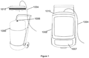
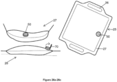
- Figures 1 and 2 show a bladder 1000 containing liquid (eg: paint in Fig. 1 , milk in Fig. 2 , fuel, or the like) contained in a sealed structure 1002 (eg: a paint tin in Fig. 1 , milk fridge in Fig. 2 , a fuel tank, or the like) and pressurized with air coming in through a tube, inlet valve supplied by either an electric compressor 1007, by a manual pressure pump 1009or some other like means.
- the bladder 1000 is connected to an outlet valve 1006 and hose 1004 with no (or minimal) mechanical parts and the contained liquid is syphoned out due to a pressure equalization effect.
- the delivery of liquid is controlled by a faucet or other trigger (not shown) at the end of the outlet valve 1006 and/or hose 1004.
- the structure 1002 can have a lid 1010 that can be threadingly fastened 1012 with the structure 1002.
- a pressure gauge 1015 can also be utilised.
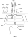
- Figures 3 to 5 show a high pressure source (eg: air tank or electric pump 2000) that is connected to the faucet 2002 via a hose 2004 and other air tight connections 2005.
- the output from the faucet 2002 is now capable of high pressure water and/or air which can be used to increase the performance of the traditional applications of the faucet 2002, including but not limited to high pressure, in sink 2010 dishwashing with increased functionality including but not limited to a sealed, splash protective cover 2011, an air knife is created by the air coming from the compressor which can be used to remove solids from the dishes 2012.
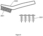
- a garbage disposal 2015 or the like for the proper disposal of the scraps could also be utilised and functional cleaning head attachments 2020 could be used to change uses of the device.
- the heads could include bristles 2021 or the like as shown in Figure 5 .
- the increased power of air and/or water can allow for new mechanical applications of the faucet including but not limited to the driving of mechanical turbines such as a handheld blender, juicer, or the like 2025.
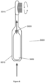
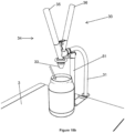
- Figures 6 , 7 and 8 show a small and mobile pressurized air canister 3000 for use in or beside a range of mobile, air powered devices (e.g. a toothbrush in Figure 6 ) and which is able to recharge simply.
- It comprises a small tank 3002 made from a strong material (eg: steel, carbon fiber, etc..) and containing a user friendly refill valve 3005 which comprises a screw on, clip on or other type of generally known assembly and is filled by either higher pressure air in a source tank 3002 to flow into a battery tank 3007 until the pressure is either equalized or the maximum pressure in the battery tank 3007 is reached or an air compressor 3009 (either electronic, manual or some other type) connected to the battery tank 3007.
- a universal battery housing 3010 allows appliances to safely consume the air in the canister in order to run the appliance 3015.
- Figure 9 shows a product container 4000 which is either single unit or a larger area / multiple unit version, free standing or contained within an already cooled environment (eg: fridge, freezer, esky, or the like) and contains a source of compressed air travelling through a vortex tube 4002, an inlet valve 4005 for the vortex heated or cooled air to enter cavities 4007 or specifically designed air outlet points to effect the temperature of the product.
- an already cooled environment eg: fridge, freezer, esky, or the like
- the device can also rapidly heat particular household items like a toaster 4010, for example.
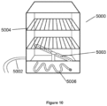
- Figure 10 shows a single unit 5000 comprising a water inlet 5002 and high pressure water and/or steam outlets 5003; racking 5004 to contain the subjects to be cooked and/or cleaned; a heating element 5006.
- the container unit 5000 can either be at atmospheric pressure or sealed to provide benefits of pressurized cooking and cleaning.
- the apparatus 5000 can be operated in a cook mode which activates either the heated water and steam for steam cooking and/or the heating element for dry cooking or clean mode which activates the heated water and steam as well as the water and steam jets.
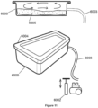
- Figure 11 shows a chamber 6000 connected to an air supply (either an air compressor or other) 6002 via a hose 6003 and can be sealed with a lid 6004.
- the subject and the additive 6005 are placed inside the chamber or container 6000 and the chamber pressurized with air for a significantly shorter time frame than existing cooking techniques.
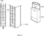
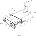
- the apparatus shown in Figures 12 and 13 comprises a pneumatic air supply (not shown), either attached to the unit 7000 or in a different physical location (not shown).
- the unit 7000 is made up of a number of air knives 7002 arranged in an assortment of ways (eg: two knives opposite each other, one large one in a line, or the like).
- a water catchment reservoir 7003; a heating element 7004 and other inclusions such as rolling devices 7006 are provided for the purpose of drying a range of household items (eg: clothing 7009), a person, dishes, car, or the like).
- Figures 14 and 15 show an improvement to traditional commercial liquid storage bags where handles 8002 and/or structural supports 8004 are added to the bag 8000 itself to aid the handling, storage and transport for the bags.
- the bag's contents go from full 8007 to empty 8009, the bag's rigid walls 8010 collapse onto the rigid base 8011 to pack down flat for disposal.
- the bag 8000 also includes a pressurised connector valve 8015.
- a liquid delivery assembly having at least one liquid delivery module 2.
- Each delivery module 2 includes a housing 3 and an associated compartment 4.
- the housing 3 has a top surface 4, bottom surface 5, side walls 6, a closed end 7 and an open end 8.
- the compartment 4 includes a bottom floor 10, side walls 11, a front wall 12, a back wall 13 defining a space 15 therebetween.
- the compartment 4 is locatable within the housing 3 and moveable with respect to the housing 3 to permit access by a user to the compartment 4 and in particular the space 15.
- the module 2 is shown as a rectangular prism it could be any suitable shape. For example, square prism, pyramid prism, cone prism, cylindrical prism, polygon prism or the like.
- the compartment 4 takes the form of a draw and includes associated draw railings 20 of the common type located on the side walls 11 and inside surfaces of walls 6 to allow the draw 4 to move smoothly into and out of the housing 3.
- a lock 21 can be included to lock the draw 4 in a closed or secured position to the housing 3.
- the lock 21 can take many known forms. For example, as shown includes a hook and catch mechanism or the like.
- the space 15 is adapted in use to receive a receptacle 25 (or bag) adapted in use to contain a liquid to be dispensed by the assembly 1 to a user.
- the assembly 1 further includes a liquid dispenser 30 which includes a conduit or tube 31 extendable in use from a dispensing nozzle 32 to a liquid receiving connector 33.
- the liquid receiving connector 33 is adapted to releaseably connect to the liquid receptacle or bag 25 by way of a connector or cap 50.
- the compartment 4 in an open position provides access to the space 15 which is adapted to receive the receptacle 25.
- the compartment is sealingly engaged with the housing 3.
- the lock 21 can ensure that the compartment 4 does not open when the bag 25 is under pressure.
- the dispenser 30 includes a handle 34 extending from the nozzle 32.
- the handle 34 connects with the conduit 31.
- the handle 34 is shown having a fixed arm 35 and a moveable or pivotable arm 36.
- Various other embodiments of the handle 34 are useable for example as shown in Figures 21a , 21b .
- a further version of the handle 34 is shown where the fixed arm 35 includes a groove 40 to receive the conduit 31 and the pivot arm 36 includes a stopper 45 which when pressed by a user will stop flow of liquid through the conduit 31.
- the handle 34 includes a guide 46, fasteners 49 and springs 70 to maintain the handle 34 along with a pivot plate 47 adapted to help pivot the movable arm 36 from the fixed arm 35.
- the handle 34 can include an ergonomic grip (not shown) or the like.
- one or more modules 2 can be connected together in series or parallel to allow dispensing of the same or different liquids simultaneously or individually.
- the assembly 1 may further include a handle mount 51 to assist with the dispensing of liquids through the handle 34 and nozzle 32.
- FIGs 24a, 24b is shown a connector or cap 50 for use with the liquid bags 25 of the delivery system 1.
- the connector 50 has a flange 57, elongate body 52 including a thread 53 on the outside and an aperture 54.
- a valve 55 and sealing ring 56 are received in use within the aperture 54.
- the connector 50 attaches to a liquid bag 25 and is operatively associated with the connector 60 of a corresponding compartment 4.
- FIGS 25a, 25b there is shown the connector 60 of the compartment 4 having a flange 61, an elongate body 62 having grooves 63 or the like to assist with installation, a valve piece 64 having a thread 65 to be received within a corresponding thread 66 within the connector 63 and to attach to an insert piece 67 also having a corresponding threaded piece 68.
- an arm 69 to attach to the conduit 31 to extend to the nozzle 32 to be dispensed.
- FIGS 26a to 26c there is shown an example of a liquid delivery bag 25 having handles 26 at either side, heat sealed edges 27 and the connector or cap 50 which could include a flip-top lid or cover 70.
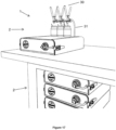
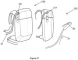
- FIG 27 there is shown the assembly 1 of the present invention incorporated into a backpack 100.
- the backpack 100 being of a standard type backpack having an aperture 101 to allow the conduit 31 to extend from the assembly 1 out to the nozzle 32 to be dispensed by a user.
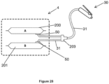
- FIG 28 there is shown a compartment 4 of the present invention holding two bags 200, 201 connected by a dual connector 203 connecting conduits 31 to allow liquids from two bags 25 to be dispensed simultaneously from a single nozzle 32.
- FIG 29 there is shown a bag 25 of the present invention including an agitator 300 to be utilised within the bag 25 to assist with keeping the liquid within the bag agitated.
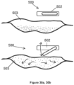
- Figures 30a and 30b show further embodiments of agitators of the present invention.
- the arm 500 is driven by a motor 502 and moves up and down or in any suitable direction. This action depresses the bag 503 and creates a wave in the liquid located within the bag 503. The wave then creates enough movement to disperse sediment if any is located in the bag and mix it with the liquid in the bag.
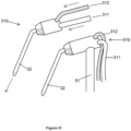
- FIG 31 there is shown a frother 310 to be used with the present invention.
- the frother 310 including a liquid line 311 and a hot air line 312 to assist with frothing liquid to be dispensed from the nozzle 32.
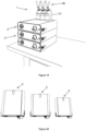
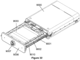
- FIGs 32 to 39 are further embodiments of the module 2 of Figure 16 .
- the main housing 9000 and pressure chamber 9001 with integrated refrigeration have a crate, tray or insert 9002 to hold the bag 9003.
- the bags 9003 arrive as a package with the crate 9002 included and can be inserted into the main housing 9000.
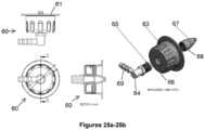
- a piercer 9005 on the other side of the draw front 9006.
- the dial 9007 has a secure valve 9013 to the bag 9003.
- the draw 9010 receives the crate 9002 which holds the bag 9003.
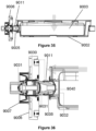
- the piercer 9005 interacts with a bag cap 9011 which will connect with break-away tabs 9020 which keep the bag 9003 sealed until broken in the chamber 9001.
- the piercer 9005 needs to be first pushed into the bag cap 9011 to get an initial seal.
- the crate 9002 is then placed into the lower drawer receptacle.
- the matching threads 9030 are engaged and the one-way valve 9031 keeps the seal intact.
- the rubber O-ring 9032 creates the seal with the one-way valve 903 1.
- the crate 9002 is then pushed into position.
- the front dial 9007 is turned to engage the thread 9030 and draws the crate in to it.
- the outlet pathway 9045 breaches the one-way valve 9031 as the dial 9007 is turned and the end of the piercer 9005 is compressed against the break way finger 9040 eventually breaking them.
- the flange 9041 on the cap 9011 compresses the gasket 9032 and creates an air tight seal isolating the bag 9003 from the chamber 9001.
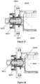
- An open pathway 9050 is created when fully engaged multiple things occur.
- the draw is then closed and the pressure chamber 9001 is created and sealed. Liquid is dispensed when pressure in the chamber increases.
- the dial 9007 is rotated to release the crate.
- the piercer 9005 is released along with the assembly.
- the one-way valve 9031 creates the seal and the remaining liquid will not spill out.
Landscapes
- Chemical & Material Sciences (AREA)
- Dispersion Chemistry (AREA)
- Engineering & Computer Science (AREA)
- Mechanical Engineering (AREA)
- Containers And Packaging Bodies Having A Special Means To Remove Contents (AREA)
- Loading And Unloading Of Fuel Tanks Or Ships (AREA)
- Devices For Dispensing Beverages (AREA)
Claims (8)
- Druckbeaufschlagte Flüssigkeitsabgabeanordnung (1) mit:
Mindestens einem Flüssigkeitsabgabemodul (2), jedes Modul beinhaltet:Ein Gehäuse (3, 9000) und ein verbundenes Fach, dieses Fach ist ein Auszug (4, 9010), der verschiebbar in dem Gehäuse (3, 9000) untergebracht und im Verhältnis zu dem Gehäuse beweglich ist, um den Zugang für einen Benutzer zu diesem Fach zu erlauben;Dieser Auszug (4, 9010), der eine herausnehmbare Kassette (9002) beinhaltet, die im Betrieb angepasst ist, einen auswechselbaren, druckbeaufschlagten Behälter (25, 9003) aufzunehmen, der eine von dieser Anordnung (1) abzugebende Flüssigkeit enthält, dieser Auszug definiert einen Raum für die Aufnahme der herausnehmbaren Kassette (9002) und des Behälters, so dass der Behälter (25, 9003) innerhalb des Raums (15) positioniert ist;der Auszug ist von einer offenen Position, die den Zugang zu dem Raum ermöglicht, beweglich in eine geschlossene Position, wodurch eine Druckkammer geschaffen und abgedichtet wird;eine Flüssigkeitsabgabe (30), die funktionsfähig mit dem Behälter (25, 9003) verbunden und angepasst ist, eine Flüssigkeit abzugeben, wenn der Druck in der Kammer ansteigt;die Abgabevorrichtung (30) beinhaltet eine Leitung (31), die von einer Abgabedüse (32) zu einem Flüssigkeitsaufnahmeanschluss (33) ausfahrbar ist, dieser Flüssigkeitsaufnahmeanschluss ist angepasst, um im Betrieb abnehmbar mit dem Flüssigkeitsbehälter (25, 9003) verbunden zu werden;wobei die Anordnung (1) ferner eine Durchstecheinrichtung (9005) beinhaltet, die angepasst ist, im Betrieb den Behälter (25, 9003) zu durchstechen, damit die in diesem Behälter befindliche Flüssigkeit zu der Düse (32) fließen kann. - Flüssigkeitsabgabeanordnung nach Anspruch 1, wobei der Behälter (25, 9003) ein druckbeaufschlagter Flüssigkeitsbeutel ist.
- Flüssigkeitsabgabeanordnung nach Anspruch 1, wobei die Abgabevorrichtung (30) einen Griff (34) beinhaltet, der sich von der Düse (32) erstreckt.
- Flüssigkeitsabgabeanordnung nach Anspruch 1, wobei die Anordnung ein oder mehrere Module (2) beinhaltet, die funktionsfähig miteinander und mit einer oder mehreren Düsen (31) verbunden sind.
- Flüssigkeitsabgabeanordnung nach Anspruch 4, wobei das eine oder die mehreren Module (2) miteinander verbindbar sind.
- Flüssigkeitsabgabeanordnung nach Anspruch 3, wobei der Griff (34) einen Stopp (45) beinhaltet, um zu verhindern, dass die Flüssigkeit durch die Leitung (31) fließt.
- Flüssigkeitsabgabeanordnung nach Anspruch 1, wobei die Leitung (31) ein Einwegartikel ist.
- Flüssigkeitsabgabeanordnung nach einem der vorhergehenden Ansprüche, ferner umfassend einen Aufschäumer (310), der die Flüssigkeit aufschäumt bevor sie an die besagte Düse abgegeben wird.
Applications Claiming Priority (3)
| Application Number | Priority Date | Filing Date | Title |
|---|---|---|---|
| AU2014905191A AU2014905191A0 (en) | 2014-12-22 | Pressure assemblies | |
| AU2015903336A AU2015903336A0 (en) | 2015-08-18 | Liquid delivery system | |
| PCT/AU2015/000761 WO2016101011A1 (en) | 2014-12-22 | 2015-12-22 | A pressurised liquid delivery system |
Publications (4)
| Publication Number | Publication Date |
|---|---|
| EP3237322A1 EP3237322A1 (de) | 2017-11-01 |
| EP3237322A4 EP3237322A4 (de) | 2018-10-17 |
| EP3237322B1 true EP3237322B1 (de) | 2024-08-07 |
| EP3237322C0 EP3237322C0 (de) | 2024-08-07 |
Family
ID=56148773
Family Applications (1)
| Application Number | Title | Priority Date | Filing Date |
|---|---|---|---|
| EP15871334.7A Active EP3237322B1 (de) | 2014-12-22 | 2015-12-22 | Ausgabesystem für eine unter druck stehende flüssigkeit |
Country Status (11)
| Country | Link |
|---|---|
| US (1) | US10427178B2 (de) |
| EP (1) | EP3237322B1 (de) |
| JP (1) | JP2018501164A (de) |
| CN (1) | CN107207234A (de) |
| AU (1) | AU2015372421B2 (de) |
| BR (1) | BR112017013366A2 (de) |
| CA (1) | CA2970549A1 (de) |
| ES (1) | ES2990982T3 (de) |
| NZ (1) | NZ732830A (de) |
| SG (1) | SG11201704937TA (de) |
| WO (1) | WO2016101011A1 (de) |
Families Citing this family (1)
| Publication number | Priority date | Publication date | Assignee | Title |
|---|---|---|---|---|
| JP1811124S (ja) * | 2022-11-04 | 2025-10-22 | 洗剤用容器 |
Citations (2)
| Publication number | Priority date | Publication date | Assignee | Title |
|---|---|---|---|---|
| US20060138164A1 (en) * | 2003-07-03 | 2006-06-29 | Goepfert Gerard F | Under counter dispenser |
| WO2007019848A2 (en) * | 2005-08-12 | 2007-02-22 | Carlsberg Breweries A/S | Device for connecting a flexible container to a beverage dispenser |
Family Cites Families (11)
| Publication number | Priority date | Publication date | Assignee | Title |
|---|---|---|---|---|
| US4337769A (en) * | 1980-08-01 | 1982-07-06 | Baxter Travenol Laboratories, Inc. | Pressure infusion module |
| US4484697A (en) * | 1980-08-27 | 1984-11-27 | Shasta Beverages, Inc. | Method and apparatus for dispensing liquid |
| US4869402A (en) * | 1986-10-22 | 1989-09-26 | Ash Jr William O | Portable beverage dispenser |
| US4796788A (en) * | 1987-08-26 | 1989-01-10 | Liqui-Box Corporation | Bag-in-box packaging and dispensing of substances which will not readily flow by gravity |
| US5411179A (en) * | 1993-08-31 | 1995-05-02 | S.O.B. Partnership | Self-contained beverage dispensing system |
| US6186361B1 (en) * | 1994-08-18 | 2001-02-13 | Creamiser Products Corporation | Liquid dispenser |
| US5772075A (en) * | 1996-02-14 | 1998-06-30 | Ash, Jr.; William O. | Portable slush beverage dispensing system |
| SE520600C2 (sv) * | 2001-11-26 | 2003-07-29 | Asept Int Ab | Portioneringsanordning |
| CN101827779B (zh) | 2007-08-20 | 2014-03-19 | 嘉士伯酿酒有限公司 | 用于饮料的模块式压力分配系统及用于该系统的模块 |
| EP2447208A1 (de) | 2010-10-29 | 2012-05-02 | AB InBev NV | Ausgabevorrichtung mit einer Scharniertür |
| EP2562129A1 (de) | 2011-08-23 | 2013-02-27 | Anheuser-Busch InBev S.A. | Reihenausschankvorrichtung für Getränke |
-
2015
- 2015-12-14 US US15/539,093 patent/US10427178B2/en active Active
- 2015-12-22 ES ES15871334T patent/ES2990982T3/es active Active
- 2015-12-22 AU AU2015372421A patent/AU2015372421B2/en active Active
- 2015-12-22 SG SG11201704937TA patent/SG11201704937TA/en unknown
- 2015-12-22 WO PCT/AU2015/000761 patent/WO2016101011A1/en not_active Ceased
- 2015-12-22 EP EP15871334.7A patent/EP3237322B1/de active Active
- 2015-12-22 CN CN201580069910.8A patent/CN107207234A/zh active Pending
- 2015-12-22 NZ NZ732830A patent/NZ732830A/en unknown
- 2015-12-22 BR BR112017013366A patent/BR112017013366A2/pt not_active Application Discontinuation
- 2015-12-22 CA CA2970549A patent/CA2970549A1/en not_active Abandoned
- 2015-12-22 JP JP2017550963A patent/JP2018501164A/ja active Pending
Patent Citations (2)
| Publication number | Priority date | Publication date | Assignee | Title |
|---|---|---|---|---|
| US20060138164A1 (en) * | 2003-07-03 | 2006-06-29 | Goepfert Gerard F | Under counter dispenser |
| WO2007019848A2 (en) * | 2005-08-12 | 2007-02-22 | Carlsberg Breweries A/S | Device for connecting a flexible container to a beverage dispenser |
Also Published As
| Publication number | Publication date |
|---|---|
| BR112017013366A2 (pt) | 2018-01-09 |
| US10427178B2 (en) | 2019-10-01 |
| AU2015372421A1 (en) | 2017-07-06 |
| EP3237322A1 (de) | 2017-11-01 |
| US20180008994A1 (en) | 2018-01-11 |
| NZ732830A (en) | 2023-06-30 |
| CA2970549A1 (en) | 2016-06-30 |
| ES2990982T3 (es) | 2024-12-02 |
| WO2016101011A1 (en) | 2016-06-30 |
| CN107207234A (zh) | 2017-09-26 |
| EP3237322C0 (de) | 2024-08-07 |
| JP2018501164A (ja) | 2018-01-18 |
| EP3237322A4 (de) | 2018-10-17 |
| AU2015372421B2 (en) | 2020-02-13 |
| SG11201704937TA (en) | 2017-07-28 |
Similar Documents
| Publication | Publication Date | Title |
|---|---|---|
| CN102448841B (zh) | 罗纹水钉 | |
| RU2563214C2 (ru) | Эргономичное сервисное устройство для машины для приготовления напитков | |
| US20100116847A1 (en) | Under-counter water cooler appliance | |
| MX2009001922A (es) | Maquina dispensadora de cubierta helada. | |
| US20200370229A1 (en) | Bulk tank detergent reservoir and dispenser in a washing machine appliance | |
| EP2395303A2 (de) | Einzel- oder Mehrfachausgabe von Getränken aus einem Massengutbehälter auf einem Kühlschrank | |
| GB2504289A (en) | Paste dispenser and paste receiving pouches | |
| EP2008554A1 (de) | System zur Lagerung und Dosierung eines Pulvers | |
| US20120318820A1 (en) | Multiple Liquid Dispenser | |
| EP3237322B1 (de) | Ausgabesystem für eine unter druck stehende flüssigkeit | |
| US11401150B2 (en) | Automated fluid dispenser system | |
| US6059146A (en) | Liquid delivery system that automatically delivers liquid from a plurality of containers | |
| EP2036853A1 (de) | Kühlvorrichtung für einen kollabierbaren Getränkebehälter | |
| WO1999000320A1 (en) | Beverage dispenser | |
| US20170240399A1 (en) | Milk dispenser | |
| US2008121A (en) | Portable beverage dispenser | |
| WO2015170992A1 (en) | Spray can with interchangeable capsule | |
| WO2013124778A1 (en) | Dispenser for refrigerated liquids for human consumption | |
| RU203821U1 (ru) | Автоматическая встраиваемая система подачи и дозирования жидкости с переносным дисплеем | |
| AU2013100721A4 (en) | Improved Device for Cleaning. The present invention relates to a new and improved device for cleaning comprising a cleaning agent, and methods thereof. | |
| JP2026506401A (ja) | 残存量の検出を伴う正確な化学薬品分配デバイス | |
| WO2000027749A1 (en) | Docking system for a rechargeable dispenser | |
| KR20100010986U (ko) | 다용도 용액(점성액)절약용기장치 | |
| AU7899598A (en) | Beverage dispenser | |
| WO2018199834A1 (en) | Collection system for used cooking oil and method for collecting used cooking oil |
Legal Events
| Date | Code | Title | Description |
|---|---|---|---|
| STAA | Information on the status of an ep patent application or granted ep patent |
Free format text: STATUS: THE INTERNATIONAL PUBLICATION HAS BEEN MADE |
|
| PUAI | Public reference made under article 153(3) epc to a published international application that has entered the european phase |
Free format text: ORIGINAL CODE: 0009012 |
|
| STAA | Information on the status of an ep patent application or granted ep patent |
Free format text: STATUS: REQUEST FOR EXAMINATION WAS MADE |
|
| 17P | Request for examination filed |
Effective date: 20170623 |
|
| AK | Designated contracting states |
Kind code of ref document: A1 Designated state(s): AL AT BE BG CH CY CZ DE DK EE ES FI FR GB GR HR HU IE IS IT LI LT LU LV MC MK MT NL NO PL PT RO RS SE SI SK SM TR |
|
| AX | Request for extension of the european patent |
Extension state: BA ME |
|
| DAV | Request for validation of the european patent (deleted) | ||
| DAX | Request for extension of the european patent (deleted) | ||
| RIC1 | Information provided on ipc code assigned before grant |
Ipc: B67D 1/12 20060101ALI20180607BHEP Ipc: B67D 1/04 20060101AFI20180607BHEP Ipc: B67D 1/00 20060101ALI20180607BHEP |
|
| A4 | Supplementary search report drawn up and despatched |
Effective date: 20180919 |
|
| RIC1 | Information provided on ipc code assigned before grant |
Ipc: B67D 1/00 20060101ALI20180913BHEP Ipc: B67D 1/04 20060101AFI20180913BHEP Ipc: B67D 1/12 20060101ALI20180913BHEP |
|
| STAA | Information on the status of an ep patent application or granted ep patent |
Free format text: STATUS: EXAMINATION IS IN PROGRESS |
|
| 17Q | First examination report despatched |
Effective date: 20190808 |
|
| STAA | Information on the status of an ep patent application or granted ep patent |
Free format text: STATUS: THE APPLICATION IS DEEMED TO BE WITHDRAWN |
|
| 18D | Application deemed to be withdrawn |
Effective date: 20211026 |
|
| 19U | Interruption of proceedings before grant |
Effective date: 20211027 |
|
| 19W | Proceedings resumed before grant after interruption of proceedings |
Effective date: 20230201 |
|
| STAA | Information on the status of an ep patent application or granted ep patent |
Free format text: STATUS: EXAMINATION IS IN PROGRESS |
|
| D18D | Application deemed to be withdrawn (deleted) | ||
| RAP3 | Party data changed (applicant data changed or rights of an application transferred) |
Owner name: AIR POUR PTY LTD |
|
| GRAP | Despatch of communication of intention to grant a patent |
Free format text: ORIGINAL CODE: EPIDOSNIGR1 |
|
| STAA | Information on the status of an ep patent application or granted ep patent |
Free format text: STATUS: GRANT OF PATENT IS INTENDED |
|
| INTG | Intention to grant announced |
Effective date: 20230810 |
|
| GRAJ | Information related to disapproval of communication of intention to grant by the applicant or resumption of examination proceedings by the epo deleted |
Free format text: ORIGINAL CODE: EPIDOSDIGR1 |
|
| STAA | Information on the status of an ep patent application or granted ep patent |
Free format text: STATUS: EXAMINATION IS IN PROGRESS |
|
| GRAP | Despatch of communication of intention to grant a patent |
Free format text: ORIGINAL CODE: EPIDOSNIGR1 |
|
| STAA | Information on the status of an ep patent application or granted ep patent |
Free format text: STATUS: GRANT OF PATENT IS INTENDED |
|
| INTC | Intention to grant announced (deleted) | ||
| INTG | Intention to grant announced |
Effective date: 20240105 |
|
| GRAS | Grant fee paid |
Free format text: ORIGINAL CODE: EPIDOSNIGR3 |
|
| GRAA | (expected) grant |
Free format text: ORIGINAL CODE: 0009210 |
|
| STAA | Information on the status of an ep patent application or granted ep patent |
Free format text: STATUS: THE PATENT HAS BEEN GRANTED |
|
| RAP3 | Party data changed (applicant data changed or rights of an application transferred) |
Owner name: AIR POUR PTY LTD |
|
| AK | Designated contracting states |
Kind code of ref document: B1 Designated state(s): AL AT BE BG CH CY CZ DE DK EE ES FI FR GB GR HR HU IE IS IT LI LT LU LV MC MK MT NL NO PL PT RO RS SE SI SK SM TR |
|
| REG | Reference to a national code |
Ref country code: CH Ref legal event code: EP |
|
| REG | Reference to a national code |
Ref country code: IE Ref legal event code: FG4D |
|
| REG | Reference to a national code |
Ref country code: DE Ref legal event code: R096 Ref document number: 602015089486 Country of ref document: DE |
|
| U01 | Request for unitary effect filed |
Effective date: 20240903 |
|
| U07 | Unitary effect registered |
Designated state(s): AT BE BG DE DK EE FI FR IT LT LU LV MT NL PT RO SE SI Effective date: 20240919 |
|
| REG | Reference to a national code |
Ref country code: ES Ref legal event code: FG2A Ref document number: 2990982 Country of ref document: ES Kind code of ref document: T3 Effective date: 20241202 |
|
| PG25 | Lapsed in a contracting state [announced via postgrant information from national office to epo] |
Ref country code: NO Free format text: LAPSE BECAUSE OF FAILURE TO SUBMIT A TRANSLATION OF THE DESCRIPTION OR TO PAY THE FEE WITHIN THE PRESCRIBED TIME-LIMIT Effective date: 20241107 |
|
| PG25 | Lapsed in a contracting state [announced via postgrant information from national office to epo] |
Ref country code: PL Free format text: LAPSE BECAUSE OF FAILURE TO SUBMIT A TRANSLATION OF THE DESCRIPTION OR TO PAY THE FEE WITHIN THE PRESCRIBED TIME-LIMIT Effective date: 20240807 Ref country code: GR Free format text: LAPSE BECAUSE OF FAILURE TO SUBMIT A TRANSLATION OF THE DESCRIPTION OR TO PAY THE FEE WITHIN THE PRESCRIBED TIME-LIMIT Effective date: 20241108 |
|
| U20 | Renewal fee for the european patent with unitary effect paid |
Year of fee payment: 10 Effective date: 20241216 |
|
| PG25 | Lapsed in a contracting state [announced via postgrant information from national office to epo] |
Ref country code: IS Free format text: LAPSE BECAUSE OF FAILURE TO SUBMIT A TRANSLATION OF THE DESCRIPTION OR TO PAY THE FEE WITHIN THE PRESCRIBED TIME-LIMIT Effective date: 20241207 |
|
| PG25 | Lapsed in a contracting state [announced via postgrant information from national office to epo] |
Ref country code: HR Free format text: LAPSE BECAUSE OF FAILURE TO SUBMIT A TRANSLATION OF THE DESCRIPTION OR TO PAY THE FEE WITHIN THE PRESCRIBED TIME-LIMIT Effective date: 20240807 |
|
| PG25 | Lapsed in a contracting state [announced via postgrant information from national office to epo] |
Ref country code: RS Free format text: LAPSE BECAUSE OF FAILURE TO SUBMIT A TRANSLATION OF THE DESCRIPTION OR TO PAY THE FEE WITHIN THE PRESCRIBED TIME-LIMIT Effective date: 20241107 |
|
| PG25 | Lapsed in a contracting state [announced via postgrant information from national office to epo] |
Ref country code: RS Free format text: LAPSE BECAUSE OF FAILURE TO SUBMIT A TRANSLATION OF THE DESCRIPTION OR TO PAY THE FEE WITHIN THE PRESCRIBED TIME-LIMIT Effective date: 20241107 Ref country code: PL Free format text: LAPSE BECAUSE OF FAILURE TO SUBMIT A TRANSLATION OF THE DESCRIPTION OR TO PAY THE FEE WITHIN THE PRESCRIBED TIME-LIMIT Effective date: 20240807 Ref country code: NO Free format text: LAPSE BECAUSE OF FAILURE TO SUBMIT A TRANSLATION OF THE DESCRIPTION OR TO PAY THE FEE WITHIN THE PRESCRIBED TIME-LIMIT Effective date: 20241107 Ref country code: IS Free format text: LAPSE BECAUSE OF FAILURE TO SUBMIT A TRANSLATION OF THE DESCRIPTION OR TO PAY THE FEE WITHIN THE PRESCRIBED TIME-LIMIT Effective date: 20241207 Ref country code: HR Free format text: LAPSE BECAUSE OF FAILURE TO SUBMIT A TRANSLATION OF THE DESCRIPTION OR TO PAY THE FEE WITHIN THE PRESCRIBED TIME-LIMIT Effective date: 20240807 Ref country code: GR Free format text: LAPSE BECAUSE OF FAILURE TO SUBMIT A TRANSLATION OF THE DESCRIPTION OR TO PAY THE FEE WITHIN THE PRESCRIBED TIME-LIMIT Effective date: 20241108 |
|
| PG25 | Lapsed in a contracting state [announced via postgrant information from national office to epo] |
Ref country code: SM Free format text: LAPSE BECAUSE OF FAILURE TO SUBMIT A TRANSLATION OF THE DESCRIPTION OR TO PAY THE FEE WITHIN THE PRESCRIBED TIME-LIMIT Effective date: 20240807 |
|
| PG25 | Lapsed in a contracting state [announced via postgrant information from national office to epo] |
Ref country code: SK Free format text: LAPSE BECAUSE OF FAILURE TO SUBMIT A TRANSLATION OF THE DESCRIPTION OR TO PAY THE FEE WITHIN THE PRESCRIBED TIME-LIMIT Effective date: 20240807 |
|
| PLBE | No opposition filed within time limit |
Free format text: ORIGINAL CODE: 0009261 |
|
| STAA | Information on the status of an ep patent application or granted ep patent |
Free format text: STATUS: NO OPPOSITION FILED WITHIN TIME LIMIT |
|
| PG25 | Lapsed in a contracting state [announced via postgrant information from national office to epo] |
Ref country code: MC Free format text: LAPSE BECAUSE OF FAILURE TO SUBMIT A TRANSLATION OF THE DESCRIPTION OR TO PAY THE FEE WITHIN THE PRESCRIBED TIME-LIMIT Effective date: 20240807 |
|
| 26N | No opposition filed |
Effective date: 20250508 |
|
| REG | Reference to a national code |
Ref country code: CH Ref legal event code: PL |
|
| PG25 | Lapsed in a contracting state [announced via postgrant information from national office to epo] |
Ref country code: CH Free format text: LAPSE BECAUSE OF NON-PAYMENT OF DUE FEES Effective date: 20241231 |
|
| PG25 | Lapsed in a contracting state [announced via postgrant information from national office to epo] |
Ref country code: IE Free format text: LAPSE BECAUSE OF NON-PAYMENT OF DUE FEES Effective date: 20241222 |
|
| PGFP | Annual fee paid to national office [announced via postgrant information from national office to epo] |
Ref country code: GB Payment date: 20251222 Year of fee payment: 11 |
|
| PGFP | Annual fee paid to national office [announced via postgrant information from national office to epo] |
Ref country code: CZ Payment date: 20251222 Year of fee payment: 11 |
|
| U20 | Renewal fee for the european patent with unitary effect paid |
Year of fee payment: 11 Effective date: 20251222 |
|
| PGFP | Annual fee paid to national office [announced via postgrant information from national office to epo] |
Ref country code: ES Payment date: 20260113 Year of fee payment: 11 |