EP3237112B1 - Belüftete mikrofluidische behälter - Google Patents
Belüftete mikrofluidische behälter Download PDFInfo
- Publication number
- EP3237112B1 EP3237112B1 EP15880455.9A EP15880455A EP3237112B1 EP 3237112 B1 EP3237112 B1 EP 3237112B1 EP 15880455 A EP15880455 A EP 15880455A EP 3237112 B1 EP3237112 B1 EP 3237112B1
- Authority
- EP
- European Patent Office
- Prior art keywords
- microfluidic
- reservoir
- vented
- fluid sample
- microfluidic device
- Prior art date
- Legal status (The legal status is an assumption and is not a legal conclusion. Google has not performed a legal analysis and makes no representation as to the accuracy of the status listed.)
- Active
Links
- 239000012530 fluid Substances 0.000 claims description 128
- 238000000034 method Methods 0.000 claims description 17
- 238000004891 communication Methods 0.000 claims description 13
- 238000013022 venting Methods 0.000 claims description 2
- 238000010586 diagram Methods 0.000 description 8
- 238000013459 approach Methods 0.000 description 6
- 239000000463 material Substances 0.000 description 6
- 239000002245 particle Substances 0.000 description 6
- 238000003860 storage Methods 0.000 description 6
- 238000006073 displacement reaction Methods 0.000 description 3
- 230000008569 process Effects 0.000 description 3
- 238000000018 DNA microarray Methods 0.000 description 2
- 238000003556 assay Methods 0.000 description 2
- 201000010099 disease Diseases 0.000 description 2
- 208000037265 diseases, disorders, signs and symptoms Diseases 0.000 description 2
- 238000003754 machining Methods 0.000 description 2
- 230000003287 optical effect Effects 0.000 description 2
- 238000012123 point-of-care testing Methods 0.000 description 2
- 238000012545 processing Methods 0.000 description 2
- 239000004065 semiconductor Substances 0.000 description 2
- 238000012360 testing method Methods 0.000 description 2
- 108090000790 Enzymes Proteins 0.000 description 1
- 102000004190 Enzymes Human genes 0.000 description 1
- 239000004593 Epoxy Substances 0.000 description 1
- 230000009471 action Effects 0.000 description 1
- 230000015572 biosynthetic process Effects 0.000 description 1
- 239000008280 blood Substances 0.000 description 1
- 210000004369 blood Anatomy 0.000 description 1
- 238000005266 casting Methods 0.000 description 1
- 230000008878 coupling Effects 0.000 description 1
- 238000010168 coupling process Methods 0.000 description 1
- 238000005859 coupling reaction Methods 0.000 description 1
- 230000001419 dependent effect Effects 0.000 description 1
- 238000001312 dry etching Methods 0.000 description 1
- 230000000694 effects Effects 0.000 description 1
- 238000005323 electroforming Methods 0.000 description 1
- 238000005516 engineering process Methods 0.000 description 1
- 238000005530 etching Methods 0.000 description 1
- 238000001914 filtration Methods 0.000 description 1
- 230000006870 function Effects 0.000 description 1
- 230000005484 gravity Effects 0.000 description 1
- 238000010030 laminating Methods 0.000 description 1
- 238000003475 lamination Methods 0.000 description 1
- 238000000608 laser ablation Methods 0.000 description 1
- 238000004519 manufacturing process Methods 0.000 description 1
- 230000007246 mechanism Effects 0.000 description 1
- 239000012528 membrane Substances 0.000 description 1
- 239000002184 metal Substances 0.000 description 1
- 238000000465 moulding Methods 0.000 description 1
- 239000013618 particulate matter Substances 0.000 description 1
- 244000052769 pathogen Species 0.000 description 1
- 238000000206 photolithography Methods 0.000 description 1
- 239000000049 pigment Substances 0.000 description 1
- 239000004033 plastic Substances 0.000 description 1
- 229920005862 polyol Polymers 0.000 description 1
- 230000000717 retained effect Effects 0.000 description 1
- 238000000926 separation method Methods 0.000 description 1
- 229910052710 silicon Inorganic materials 0.000 description 1
- 239000010703 silicon Substances 0.000 description 1
- 238000004528 spin coating Methods 0.000 description 1
- 238000004544 sputter deposition Methods 0.000 description 1
- 239000003053 toxin Substances 0.000 description 1
- 231100000765 toxin Toxicity 0.000 description 1
- 108700012359 toxins Proteins 0.000 description 1
- 238000012546 transfer Methods 0.000 description 1
- 238000001039 wet etching Methods 0.000 description 1
- 238000009736 wetting Methods 0.000 description 1
Images


Classifications
-
- B—PERFORMING OPERATIONS; TRANSPORTING
- B01—PHYSICAL OR CHEMICAL PROCESSES OR APPARATUS IN GENERAL
- B01L—CHEMICAL OR PHYSICAL LABORATORY APPARATUS FOR GENERAL USE
- B01L3/00—Containers or dishes for laboratory use, e.g. laboratory glassware; Droppers
- B01L3/50—Containers for the purpose of retaining a material to be analysed, e.g. test tubes
- B01L3/502—Containers for the purpose of retaining a material to be analysed, e.g. test tubes with fluid transport, e.g. in multi-compartment structures
- B01L3/5027—Containers for the purpose of retaining a material to be analysed, e.g. test tubes with fluid transport, e.g. in multi-compartment structures by integrated microfluidic structures, i.e. dimensions of channels and chambers are such that surface tension forces are important, e.g. lab-on-a-chip
- B01L3/502723—Containers for the purpose of retaining a material to be analysed, e.g. test tubes with fluid transport, e.g. in multi-compartment structures by integrated microfluidic structures, i.e. dimensions of channels and chambers are such that surface tension forces are important, e.g. lab-on-a-chip characterised by venting arrangements
-
- C—CHEMISTRY; METALLURGY
- C12—BIOCHEMISTRY; BEER; SPIRITS; WINE; VINEGAR; MICROBIOLOGY; ENZYMOLOGY; MUTATION OR GENETIC ENGINEERING
- C12M—APPARATUS FOR ENZYMOLOGY OR MICROBIOLOGY; APPARATUS FOR CULTURING MICROORGANISMS FOR PRODUCING BIOMASS, FOR GROWING CELLS OR FOR OBTAINING FERMENTATION OR METABOLIC PRODUCTS, i.e. BIOREACTORS OR FERMENTERS
- C12M23/00—Constructional details, e.g. recesses, hinges
- C12M23/02—Form or structure of the vessel
- C12M23/16—Microfluidic devices; Capillary tubes
-
- C—CHEMISTRY; METALLURGY
- C12—BIOCHEMISTRY; BEER; SPIRITS; WINE; VINEGAR; MICROBIOLOGY; ENZYMOLOGY; MUTATION OR GENETIC ENGINEERING
- C12M—APPARATUS FOR ENZYMOLOGY OR MICROBIOLOGY; APPARATUS FOR CULTURING MICROORGANISMS FOR PRODUCING BIOMASS, FOR GROWING CELLS OR FOR OBTAINING FERMENTATION OR METABOLIC PRODUCTS, i.e. BIOREACTORS OR FERMENTERS
- C12M29/00—Means for introduction, extraction or recirculation of materials, e.g. pumps
- C12M29/20—Degassing; Venting; Bubble traps
-
- C—CHEMISTRY; METALLURGY
- C12—BIOCHEMISTRY; BEER; SPIRITS; WINE; VINEGAR; MICROBIOLOGY; ENZYMOLOGY; MUTATION OR GENETIC ENGINEERING
- C12M—APPARATUS FOR ENZYMOLOGY OR MICROBIOLOGY; APPARATUS FOR CULTURING MICROORGANISMS FOR PRODUCING BIOMASS, FOR GROWING CELLS OR FOR OBTAINING FERMENTATION OR METABOLIC PRODUCTS, i.e. BIOREACTORS OR FERMENTERS
- C12M41/00—Means for regulation, monitoring, measurement or control, e.g. flow regulation
- C12M41/48—Automatic or computerized control
-
- G—PHYSICS
- G01—MEASURING; TESTING
- G01N—INVESTIGATING OR ANALYSING MATERIALS BY DETERMINING THEIR CHEMICAL OR PHYSICAL PROPERTIES
- G01N33/00—Investigating or analysing materials by specific methods not covered by groups G01N1/00 - G01N31/00
- G01N33/48—Biological material, e.g. blood, urine; Haemocytometers
- G01N33/483—Physical analysis of biological material
- G01N33/487—Physical analysis of biological material of liquid biological material
- G01N33/48707—Physical analysis of biological material of liquid biological material by electrical means
-
- B—PERFORMING OPERATIONS; TRANSPORTING
- B01—PHYSICAL OR CHEMICAL PROCESSES OR APPARATUS IN GENERAL
- B01L—CHEMICAL OR PHYSICAL LABORATORY APPARATUS FOR GENERAL USE
- B01L2200/00—Solutions for specific problems relating to chemical or physical laboratory apparatus
- B01L2200/06—Fluid handling related problems
- B01L2200/0684—Venting, avoiding backpressure, avoid gas bubbles
-
- B—PERFORMING OPERATIONS; TRANSPORTING
- B01—PHYSICAL OR CHEMICAL PROCESSES OR APPARATUS IN GENERAL
- B01L—CHEMICAL OR PHYSICAL LABORATORY APPARATUS FOR GENERAL USE
- B01L2200/00—Solutions for specific problems relating to chemical or physical laboratory apparatus
- B01L2200/10—Integrating sample preparation and analysis in single entity, e.g. lab-on-a-chip concept
-
- B—PERFORMING OPERATIONS; TRANSPORTING
- B01—PHYSICAL OR CHEMICAL PROCESSES OR APPARATUS IN GENERAL
- B01L—CHEMICAL OR PHYSICAL LABORATORY APPARATUS FOR GENERAL USE
- B01L2300/00—Additional constructional details
- B01L2300/06—Auxiliary integrated devices, integrated components
- B01L2300/0681—Filter
-
- B—PERFORMING OPERATIONS; TRANSPORTING
- B01—PHYSICAL OR CHEMICAL PROCESSES OR APPARATUS IN GENERAL
- B01L—CHEMICAL OR PHYSICAL LABORATORY APPARATUS FOR GENERAL USE
- B01L2300/00—Additional constructional details
- B01L2300/08—Geometry, shape and general structure
- B01L2300/0809—Geometry, shape and general structure rectangular shaped
- B01L2300/0816—Cards, e.g. flat sample carriers usually with flow in two horizontal directions
-
- B—PERFORMING OPERATIONS; TRANSPORTING
- B01—PHYSICAL OR CHEMICAL PROCESSES OR APPARATUS IN GENERAL
- B01L—CHEMICAL OR PHYSICAL LABORATORY APPARATUS FOR GENERAL USE
- B01L2400/00—Moving or stopping fluids
- B01L2400/04—Moving fluids with specific forces or mechanical means
- B01L2400/0403—Moving fluids with specific forces or mechanical means specific forces
- B01L2400/0433—Moving fluids with specific forces or mechanical means specific forces vibrational forces
- B01L2400/0439—Moving fluids with specific forces or mechanical means specific forces vibrational forces ultrasonic vibrations, vibrating piezo elements
-
- B—PERFORMING OPERATIONS; TRANSPORTING
- B01—PHYSICAL OR CHEMICAL PROCESSES OR APPARATUS IN GENERAL
- B01L—CHEMICAL OR PHYSICAL LABORATORY APPARATUS FOR GENERAL USE
- B01L2400/00—Moving or stopping fluids
- B01L2400/04—Moving fluids with specific forces or mechanical means
- B01L2400/0403—Moving fluids with specific forces or mechanical means specific forces
- B01L2400/0442—Moving fluids with specific forces or mechanical means specific forces thermal energy, e.g. vaporisation, bubble jet
Definitions
- Microfluidics is a technology that applies across a variety of disciplines including engineering, physics, chemistry, microtechnology and biotechnology. Microfluidics involves the study of small volumes of fluid and how to manipulate, control and use such small volumes of fluid in various microfluidic systems and devices such as microfluidic chips.
- micro fluidic biochips referred to as "lab-on-chip" are used in the field of molecular biology to integrate assay operations for purposes such as analyzing enzymes and DNA, detecting biochemical toxins and pathogens, diagnosing diseases, etc.
- WO 2014/178827 describes a microfluidic sensing device and system which can include: a channel; a fluid inlet to pass fluid into the channel from a reservoir; a sensor disposed in the channel; and a pump actuator disposed in the channel apart from the sensor to induce fluid flow into the channel.
- US 2014/0250985 describes a sensing sensor and sensing device using piezoelectric resonator.
- Microfluidic biochips can be employed in point of care testing to enable assay operations at a location associated with an individual to be tested. For example, in various point of care approaches to microfluidic testing a sample may be analyzed by a sensor in microfluidic testing device to give an indication of a disease state, among other possible conditions.
- Some approaches to point of care testing employ sealed or open fluid collection basins.
- the basins may serve to both collect a fluid sample to be analyzed and retain the fluid sample once analyzed and/or may rely on a microfluidic pump and/or gravity to convey an analyzed fluid sample (i.e., a volume of a fluid sample that has been tested) to the basins.
- Such approaches may not be suitably employed with a fluid sample communicated by an actuator (e.g., a thermal resistor) and a corresponding nozzle(s) into the basins as attempting to employ an actuator and/or a nozzle in such approaches may result in inaccuracies, such as those due to pressurizing the sealed fluid collection basin (e.g., pressurization at least in part to addition of air associated with the sample into the sealed fluid collection basin) and/or undesirably conveying some or all of the fluid sample (e.g., a pressurized fluid sample) to an environment surrounding the basin, among other difficulties.
- an actuator e.g., a thermal resistor
- a nozzle(s) into the basins may result in inaccuracies, such as those due to pressurizing the sealed fluid collection basin (e.g., pressurization at least in part to addition of air associated with the sample into the sealed fluid collection basin) and/or undesirably conveying some or all of the fluid sample (e.g.,
- Examples of the present disclosure include vented microfluidic reservoirs and methods, systems, and computer-readable media with executable instructions employed with the vented microfluidic reservoirs.
- Vented microfluidic reservoirs include a housing and a vent coupled to the housing to vent air associated with a fluid sample (i.e., an analyzed fluid sample) communicated into the housing to an environment surrounding a microfluidic device coupled to the housing.
- the vented microfluidic reservoirs negate effects of air introduced with a fluid sample (e.g., introduced by actuation of an actuator via nozzle into the vented microfluidic reservoir) and store an analyzed fluid sample in the reservoir so it can be safely discarded (e.g., without leakage).
- the vented microfluidic reservoirs can, for example, be employed with a nozzle in a microfluidic device that provides an ejection mechanism to move a fluid sample through the microfluidic device and into the vented microfluidic reservoirs.
- the fluid sample is retained in the vented microfluidic reservoirs while air associated with the sample is vented, via a vent, to a surrounding environment in an effort to avoid pressurizing the reservoir while still retaining an entirety of the fluid sample in a volume of a housing of the vented microfluidic reservoirs.
- Figure 1 illustrates a diagram of an example of a microfluidic diagnostic system 100 including an example of a microfluidic device with a vented microfluidic reservoir according to the present invention.
- the microfluidic diagnostic system 100 includes a microfluidic device 102, an optional electronic controller 106, and/or the computing device 108.
- the microfluidic device 102 includes a fluid receiving structure 125, channel(s) 126, actuator(s) 128, optionally filters(s) 130, optionally an electrical interface 132, sensor(s) 131, a vented microfluidic reservoir (i.e., a vented reservoir), a vent(s) 133, and nozzle(s) 123.
- microfluidic diagnostic system 100 in the microfluidic device 102, and an electronic controller 106, and a computing device 108 and/or arranged in various configurations to promote vented microfluidic reservoirs, as described herein.
- a particular number of elements are illustrated (e.g., a single channel 126) there can be more (e.g., two or more channels 126) of various elements such as the fluid receiving structure 125, the channel(s) 126, the actuator(s) 128, filters(s) 130, the electrical interface 132, the sensor(s) 131, the vented microfluidic reservoir, the vent(s) 133, and/or the nozzle(s) 123, etc. depending upon a desired application of the microfluidic diagnostic system 100.
- the microfluidic device 102 can be implemented as a chip-based device in some examples.
- the structures and components of a chip-based microfluidic device 102 can be fabricated using integrated circuit micro fabrication techniques such as electroforming, laser ablation, anisotropic etching, sputtering, dry and wet etching, photolithography, casting, molding, stamping, machining, spin coating, laminating, and so on.
- the fluid receiving structure 125 refers to a structure having a volume to receive a fluid sample and communicate the same to the channel(s) 126 of the microfluidic device 102. That is, a fluid sample can be placed or otherwise provided to the fluid receiving structure 125.
- the fluid sample can be a fluid having particles (e.g., a blood sample, an ink containing particulate matter(s) such as a pigment(s), among other possible types of fluid).
- the fluid sample may pass through a filter(s) 130 disposed in the inlet(s) of the channel(s).
- the filter(s) 130 can prevent particles in the fluid sample of a particular size (depending on the size of the filter(s) 130 from entering the channel(s) 126.
- the fluid receiving structure 125 can be located on and/or formed in an outer surface (i.e., a cassette) of the microfluidic device 102. However, the present disclosure is not so limited.
- the fluid receiving structure 125 can be coupled to and/or integral with an outer surface of the microfluidic device 102 and/or a microfluidic chip included in the microfluidic device.
- a fluid sample can be introduced from the fluid receiving structure at an inlet(s) into the channels 126, passed through the channels(s) 126, processed by the micro fluidic device 102, and communicated to a housing of the vented micro fluidic reservoir 127 for storage therein.
- the senor(s) 131 is disposed in the channel(s) 126 near the inlet(s) (e.g., closer to the fluid receiving structure 125 than the actuator(s) 128). In another example, the sensor(s) 131 is disposed in the inlet of the channel(s) 126.
- the sensor(s) 131 can be an impedance sensor formed using various semiconductor formation techniques. The sensor(s) 131 can detect impedance changes as particles in the fluid sample pass over and/or near the sensor(s) 131.
- the actuator(s) 128 is disposed near a closed end of the channel(s) 126 downstream from the sensors (131).
- the actuator(s) 128 can be implemented using a wide variety of structures suitable to communicate a fluid sample from the micro fluidic device 102 to the vented reservoir 127.
- the actuator(s) 128 can be a thermal resistor(s) that produces vapor bubbles to create fluid displacement of the fluid sample within the channel(s) 126.
- Actuators 128 can also be implemented as piezo elements (e.g., PZT) whose electrically induced deflections generate fluid displacements within the channel(s) 126.
- Other deflective membrane elements activated by electrical, magnetic, and other forces are also possible for use in implementing the actuator(s) 128.
- the displaced fluid sample can be ejected from the nozzle(s) 123 and/or moved within the channel(s) 126.
- the nozzle(s) 123 refer to ejection nozzles suitable for use with actuator(s) 128.
- the nozzle(s) 123 disposed in or along the channel(s) 126.
- nozzle(s) 123 can be adjacent to the sensor(s) 131 in the channel(s) 126.
- the actuators 128 and/or the nozzle(s) 123 can directly or indirectly impart air along with the displaced fluid sample. Such air can be imparted into the channel(s) 126 and/or the vented micro fluidic reservoir 127, among other components. In some other approaches to storing a fluid sample, imparting of air along with the fluid sample into a storage chamber may undesirably lead to pressurization of the storage chamber and/or undesirably impact a flow rate of the fluid sample into the storage chamber, among other undesired impacts of having air associated with a fluid sample.
- the vented micro fluidic reservoir 127 accounts for such air by allowing the air to be vented via a vent(s) 133, as described herein, coupled to a housing of the vented micro fluidic reservoir to an environment surrounding the microfluidic device so the vented microfluidic reservoir 127 does not become pressurized (e.g., does not reach or maintain a pressurized state).
- the electronic controller 106 includes a controller 134,10 circuits 136, and a memory 138.
- the electronic controller 106 comprises a programmable device that includes machine-readable instructions, for example, on non-transitory processor and/or computer-readable media (e.g., the memory 138). It is to be understood that the electronic controller can execute instructions (illustrated as firmware 140), be implemented using hardware, instructions, or a combination thereof. For example, all or a portion of the electronic controller 106 can be implemented using a programmable logic device (PLD, application specific integrated circuit (ASIC), or the like. In some examples, the electronic controller 106 receives power from the computing device 108.
- the electronic controller 106 can include a power supply 142.
- the electronic controller 106 is under control of the computing device 108.
- the computing device 108 can send and receive data to and from the electronic controller 106, including command information for controlling the micro fluidic device 102 and sensor data obtained from the micro fluidic device 102.
- the electronic controller 106 is coupled to the electrical interface 132 for energizing the actuator(s) 128 and sensor(s) 131. For instance, a fluid sample is passed by actuation via the actuator(s) 128 through channels 126, as described herein, and analyzed by a sensor(s) 131 included in the channels 126 under control of the electronic controller 106.
- the micro fluidic device 102 provides an electrical output signal representing the sensor data to the electronic controller 106.
- the computing device 108 includes a central processing unit (CPU) 110, various support circuits 112, memory 114, various input/output circuits 116, and an external interface 118.
- the CPU 110 can include any number of microprocessors capable of executing instructions stored by a memory 114.
- CPU 110 can be integrated in a single device or distributed across multiple devices (e.g., computing device and/or the microfluidic device, a server, etc.).
- the memory 114 can include random access memory, read only memory, cache memory, magnetic read/write memory, or the like or any combination of such memory devices.
- Memory 114 can include a number of memory components capable of storing instructions that can be executed by CPU 110.
- Such memory 114 can be a non-transitory computer readable media.
- Memory 114 can be integrated in a single device or distributed across multiple devices. Further, memory 114 can be fully or partially integrated in the same device as CPU 110 or it can be separate but accessible to that device and CPU 110.
- the memory 114 can store an operating system (OS) 109 and a driver 111.
- the OS 109 and the driver 111 can include instructions executable by the CPU 110 for controlling the computing device 108 and the electronic controller 106 through the external interface 118.
- the driver 111 provides a connection between the OS 109 and the electronic controller 106.
- the computing device 108 comprises a programmable device that includes machine-readable instructions, for example, on non-transitory processor/computer-readable media (e.g., the memory 114).
- the support circuits 112 can include cache, power supplies, clock circuits, data registers, and the like.
- the circuits 116 can cooperate with the external interface 118 to facilitate communication with the electronic controller 106 over a communication medium 119.
- the external interface 118 can include a universal serial bus (USB) controller capable of sending and receiving data to the electronic controller 106, as well as providing power to the electronic controller 106, over a USB cable. It is to be understood that other types of electrical, optical, or RF interfaces to the electronic controller 106 can be used to send and receive data and/or provide power.
- the communication medium 119 can be any type of electrical, optical, radio frequency (RF), or the like transfer path.
- the computing device 108 can include a display 120 through which the OS 109 can provide a user interface (UI) 122.
- UI user interface
- a user can use the UI 122 to interact with the OS 109 and the driver 111 to control the electronic controller 106, and display data received from the electronic controller 106.
- a user can refer to a healthcare professional and/or an individual to be tested (i.e., a patient). However, examples are not so limited, and a user can refer to any type of user other than healthcare professionals and/or a user to be tested.
- the computing device 108 can also display data received from the electronic controller 106 and/or the microfluidic device 102.
- the computing device 108 can be a device such as a "smart phone", a tablet computer, or other types of suitable computing devices to promote vented microfluidic reservoirs, as described herein.
- FIG. 2 illustrates a schematic diagram of an example of a microfluidic device including a vented microfluidic reservoir 227 according to the present invention.
- the microfluidic device 202 includes a channel 226 (i.e., a microfluidic channel), an actuator 228, a sensor 231, an inlet 251 to receive a fluid sample 250 from a fluid receiving structure 225, and a nozzle(s) 223 (e.g., an outlet from the channel 226 to a vented microfluidic reservoir 227).
- a filter 230 e.g., a mesh filter
- the shape of the fluid channel 226 is shown as being "u-shaped", this is not intended as a limitation on the shape of the channel 226.
- the shape of the channel 226 can include other shapes, such as curved shapes, snake-like shapes, shapes with corners, combinations thereof, and so on.
- the channel 226 is not shown to any particular scale or proportion.
- the width of the channel 226 as fabricated on a device can vary from any scale or proportion shown in the drawings of this disclosure.
- the arrows in the channel indicate an example of a direction of fluid flow of a fluid sample through the channel 226.
- the inlet 251 provides an opening for the channel 226 to receive the fluid sample.
- the filter 230 is disposed in the inlet 251.
- the filter 230 prevents particles in the fluid sample of a particular size (depending on the size of the filter 230) from entering the channel 226.
- the inlet 251 can have a larger width and volume than the channel 226. That is, a volume of the inlet 251 can be greater than a volume of the channel 226. Inlet can enable a fluid sample to flow from the fluid receiving structure 225 into the channel 226.
- the senor 231 is disposed in the channel 226.
- the sensor 231 can be an impedance sensor formed using various semiconductor techniques.
- the sensor 231 can detect impedance changes as particles in the fluid sample pass over the sensor 231.
- the actuator 228 is disposed near a closed end of the channel 226 downstream from the sensor 231.
- the actuator 228 can be a fluidic inertial actuator, which can be implemented using a wide variety of structures.
- the actuator 228 can be a thermal resistor that produces vapor bubbles to create fluid displacement within the channel 226.
- the displaced fluid sample can be ejected from the nozzle(s) 223 into a vented fluid reservoir 227.
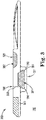
- FIG 3 illustrates a diagram of a side view of an example of a microfluidic device including a vented microfluidic reservoir according to the present disclosure.
- the microfluidic device 302 includes a housing 380 coupled to the microfluidic device 302 to provide fluid communication of a fluid sample from a fluid receiving structure 325 of the microfluidic device 302 through a channel (not shown in Figure 3 for ease of illustration) of the microfluidic device 302 by a sensor (not shown) in the channel into the housing 380 and includes a vent 386 coupled to the housing 380 (e.g., coupled by a vent tube 385) to vent air associated with the fluid sample communicated into the housing 380 to an environment 390 surrounding the microfluidic device 302.
- a vent 386 coupled to the housing 380 (e.g., coupled by a vent tube 385) to vent air associated with the fluid sample communicated into the housing 380 to an environment 390 surrounding the microfluidic device 302.
- the microfluidic device 302 includes a fluid receiving structure 325, as described herein, located on a top portion of the vented microfluidic reservoir 327 and the vented microfluidic reservoir 327 located on a bottom portion of the microfluidic device 302. Fluid introduced into the fluid receiving structure 325 can pass through a fluidic path including vented reservoir 327, as illustrated in Figure 3 .
- the vented microfluidic reservoir 327 including a housing thereof is located on an opposing side of a microfluidic device chip and/or the microfluidic device relative to the fluid receiving structure.
- the fluid receiving structure 325 and the vented microfluidic reservoir 327 are in fluid communication such that a fluid sample (e.g., at least a portion of the sample channel(s), actuators(s), nozzle(s), among other component described herein that have been omitted in Figure 3 for ease of illustration, into the vented microfluidic reservoir 327.
- a fluid sample e.g., at least a portion of the sample channel(s), actuators(s), nozzle(s), among other component described herein that have been omitted in Figure 3 for ease of illustration
- the vented microfluidic reservoir 327 includes a housing 380 or other structure substantially enclosing and defining a volume 381 of the vented microfluidic reservoir 327.
- the housing 380 can enclose the volume 381 other than at opening(s) in the housing 380 permitting communication of a fluid sample into the housing and/or permitting air associated with a fluid sample to be vented from the vented microfluidic reservoir 327 via the vent 386).
- the fluid receiving structure 325 has a volume 382 that is less than a volume of the vented microfluidic reservoir 325.
- the volume of the vented microfluidic reservoir is in a range from 15 picoliters to 1000 microliters.
- the volume of the vented microfluidic reservoir can have from a lower limit of 15 picoliters, 50 picoliters, or 75 picoliters to an upper limit of 1000 microliters, 500 microliters, or 1 microliters of the total weight of the polyether-acetal polyol.
- a volume of a vent tube, as described herein, is not included in the volume of the vented microfluidic reservoir.
- the housing 380 and/or a vent tube 386 can be made of a same or different material as the microfluidic device 302.
- the housing 380 can be coupled to and/or integral with an outer surface the microfluidic device 302.
- the housing 380 is integral with the microfluidic device and not removable therefrom.
- Such examples can promote safe storage of a fluid sample (e.g., without spilling) in applications such as those involving bio fluids or otherwise sensitive fluids and/or in single use applications, among other applications.
- the volume 381 includes a grooved region 384 or regions that can act as wetting surface(s) (e.g., enable substantially uniform flow of a fluid sample into and/or throughout the vented microfluidic reservoir 327) to promote communication of fluid to and/or storage of fluid in the grooved region 384.
- housing 380 includes a grooved region 384 located along at least a portion of a periphery of the housing 380 located continuously along a periphery of the housing 380 to retain at least some of the fluid sample in the grooved region.
- the grooved region can be varied in size and/or shape to retain some or all of a fluid sample communicated to the vented microfluidic reservoir 327 depending upon a desired application.
- the grooved region 384 can be a "U-shaped" region extending partially into housing 380 suitable to retain a fluid sample therein, among other possible shapes.
- grooved region 384 can extend into another portion of the lower portion of the volume 381 other than along the periphery of the housing.
- the systems employing vented microfluidic reservoirs of the present invention include a vented microfluidic reservoir including a housing defining a volume of the vented microfluidic reservoir, an ejection nozzle(s) to cause flow of a fluid sample into the volume of the vented microfluidic reservoir; and a vent coupled to the vented microfluidic reservoir to vent air imparted by the flow of the fluid sample into the housing, among other components such as those described herein.
- the systems include a housing having a grooved region, as described herein, located along a periphery of the housing to retain at least some of a fluid sample in the grooved region.
- systems can have the vented microfluidic reservoir located on a bottom of a microfluidic device relative to an electrical interface located on a side of the microfluidic device.
- the vent can be located proximate to an interface with a computing device of the microfluidic device.
- vent tube 385 couples the vent 386 to the vented microfluidic reservoir 327.
- Vent tube 385 refers to a conduit formed at least partially in (e.g., passing through at least a portion of) the microfluidic reservoir.
- the vent tube 385 can be formed at least partially within the microfluidic device 302 reservoir, for instance, through a machining and/or a lamination process(es), among other suitable processes to form the vent tube 385.
- the vent tube 385 is formed entirely within the microfluidic device 302 (i.e., internally within) in a manner to convey air from the microfluidic reservoir 327 to vent 386 without any openings other than at the respective ends of the vent tube 385 (e.g., an opening at the vent 386 and an opening in a housing of the vented microfluidic reservoir 327). That is, the vent tube 385 provides an indirect path for air imparted by the flow of at least a subset of the fluid sample into a housing 380 of the vented microfluidic reservoir 327 to exit therefrom.
- the vent 386 is a fixed, unobstructed orifice.
- vent tube can be coupled to an opening in the housing 380 of the vented microfluidic reservoir 327 that is different than (e.g., separate and distinct from an opening associated with an inlet from a channel(s) into the microfluidic reservoir 327.
- Vent tube 385 is separate and distinct from the channel(s) providing a fluid sample and air associated with the fluid sample to the vented microfluidic reservoir 380. That is, the fluid sample is provided to the vented microfluidic reservoir 380 by the channel(s) that is a different structure than a structure of the vent tube 385.
- the vent tube can be a dedicated vent tube that is not coupled to a fluid receiving structure.
- the vent 386 is separate and distinct from the fluid receiving structure 325.
- the vent 386 can be located proximate to (e.g., included in or near) an electrical interface 388.
- the electrical interface can be proximate with a computing device (e.g., when the microfluidic device is coupled to the computing device) and/or a portion of a chip on a chip based microfluidic device 302.
- Electrical interface 388 can provide a coupling point between a computing device and the microfluidic device 302 and/or provided a point of attachment suitable to attach at least a portion of a chip, enable communication (e.g., communication of commands from the computing device to the microfluidic device to operate elements such as the actuators, sensors, etc. of the microfluidic device), among other possibilities.
- Positioning the vent 386 proximate the electrical interface 388 can ensure adequate separation between electronics that may be included in the electrical interface 388 and a fluid sample placed into the microfluidic device 302 via the fluid receiving structure 325.
- vent tube 385 can be included in a plurality of vent tubes 385 each in communication (e.g., fluid communication) with a vent(s) and/or a single vent tube 385 can be in communication with a plurality of vents, among other possibilities.
- vent tube 385 can be formed of the same material as the microfluidic device (e.g., a material forming the outer surface (i.e., a cassette) of the microfluidic device 302).
- the present disclosure is not so limited. That is vent tube can be formed entirely or in part of a different material than the micro fluidic device.
- suitable materials to form the vent tube 385 include silicon, epoxy, plastic, metal, and/or combinations thereof, among other materials suitable to form the vent tube 385.
- Figure 4 illustrates a flow diagram of an example of a method employing a vented microfluidic reservoir according to the present disclosure.
- the method includes analyzing a fluid sample. Analyzing includes utilizing a sensor such as those described herein to measure various information and/or properties (e.g., impedance) of a sample.
- a sensor such as those described herein to measure various information and/or properties (e.g., impedance) of a sample.
- the method includes causing a flow of the analyzed fluid sample into a volume of a vented microfluidic reservoir, as shown at 497.
- Causing refers to causing a flow of the sample, for instance, by actuation of actuators and/or nozzles, as described herein. Such a flow egress from the nozzles into the vented microfluidic reservoir. That is, causing a flow of the analyzed fluid sample ensures introducing a flow of at least the subset of the analyzed fluid sample from the channel(s) into the vented microfluidic reservoir.
- the method can include introducing a volume of an analyzed fluid sample into the vented microfluidic reservoir where the vented microfluidic reservoir has a greater volume than a volume of a fluid receiving structure.
- the volume of the analyzed fluid caused to flow into the vented microfluidic reservoir is less than a volume of the vented microfluidic reservoir. That is, the comparatively large volume of the vented microfluidic reservoir relative to the fluid receiving structure promotes retaining all of a fluid sample (e.g., all of an analyzed fluid sample) in the vented microfluidic reservoir.
- the method includes venting air associated with (included in the fluid sample and/or entering the vented microfluidic reservoir along with the fluid sample) the analyzed fluid sample from the vented microfluidic reservoir via a vent coupled to the reservoir, as described herein.
- logic is an alternative or additional processing resource to perform a particular action and/or function, etc., described herein, which includes hardware, e.g., various forms of transistor logic, application specific integrated circuits (ASICs), etc., as opposed to computer executable instructions, e.g., software firmware, etc., stored in memory and executable by a processor.
- hardware e.g., various forms of transistor logic, application specific integrated circuits (ASICs), etc.
- ASICs application specific integrated circuits
- the term “and/or” includes any and all combinations of a number of the associated listed items.
- the term “or,” unless otherwise noted, means logically inclusive or. That is, “A or B” can include (only A), (only B), or (both A and B). In other words, “A or B” can mean “A and/or B” or "one or more of A and B.”
Landscapes
- Chemical & Material Sciences (AREA)
- Health & Medical Sciences (AREA)
- Engineering & Computer Science (AREA)
- Life Sciences & Earth Sciences (AREA)
- Zoology (AREA)
- Organic Chemistry (AREA)
- Bioinformatics & Cheminformatics (AREA)
- Biomedical Technology (AREA)
- Wood Science & Technology (AREA)
- General Health & Medical Sciences (AREA)
- Analytical Chemistry (AREA)
- Biochemistry (AREA)
- Genetics & Genomics (AREA)
- Sustainable Development (AREA)
- General Engineering & Computer Science (AREA)
- Microbiology (AREA)
- Biotechnology (AREA)
- Clinical Laboratory Science (AREA)
- Hematology (AREA)
- Dispersion Chemistry (AREA)
- Physics & Mathematics (AREA)
- Chemical Kinetics & Catalysis (AREA)
- Food Science & Technology (AREA)
- Urology & Nephrology (AREA)
- Medicinal Chemistry (AREA)
- Molecular Biology (AREA)
- General Physics & Mathematics (AREA)
- Immunology (AREA)
- Pathology (AREA)
- Computer Hardware Design (AREA)
- Biophysics (AREA)
- Automatic Analysis And Handling Materials Therefor (AREA)
- Physical Or Chemical Processes And Apparatus (AREA)
Claims (14)
- Mikrofluidikvorrichtung (302), die Folgendes umfasst:einen Einlass (251), um eine Fluidprobe von einer Fluidaufnahmestruktur (225) aufzunehmen;einen belüfteten Mikrofluidikbehälter (327), der sich an einem unteren Abschnitt der Mikrofluidikvorrichtung befindet, wobei sich die Fluidaufnahmestruktur an einem oberen Abschnitt des belüfteten Mikrofluidikbehälters befindet;einen Kanal (226) zwischen der Fluidaufnahmestruktur und dem belüfteten Mikrofluidikbehälter;einen Sensor (231) in dem Kanal;eine Düse (223); undein Bedienungselement (228), das nahe einem geschlossenen Ende des Kanals stromabwärts des Sensors angeordnet und der Düse zugehörig ist, um einen Fluss der Fluidprobe von dem Kanal in den belüfteten Mikrofluidikbehälter zu bewirken;wobei der belüftete Mikrofluidikbehälter Folgendes umfasst:ein Gehäuse (380), das ein Volumen (381) des belüfteten Mikrofluidikbehälters definiert; undeine mit dem Gehäuse gekoppelte Belüftung (386), um Luft, die der Fluidprobe zugehörig ist, die in das Gehäuse kommuniziert wird, in eine Umgebung zu entlüften, die die Mikrofluidikvorrichtung umschließt, undwobei das Gehäuse und das Volumen einen gerillten Bereich (384) beinhalten, der sich entlang eines Umfangs des Gehäuses befindet, um die Fluidprobe in Kommunikation mit dem belüfteten Mikrofluidikbehälter zu halten.
- Mikrofluidikvorrichtung nach Anspruch 1, wobei die Belüftung durch ein Belüftungsrohr (385) mit dem Gehäuse gekoppelt ist.
- Mikrofluidikvorrichtung nach Anspruch 2, wobei das Belüftungsrohr von dem Kanal getrennt und verschieden ist.
- Mikrofluidikvorrichtung nach Anspruch 1, wobei sich das Gehäuse auf einer gegenüberliegenden Seite der Mikrofluidikvorrichtung relativ zu der Fluidaufnahmestruktur befindet.
- Mikrofluidikvorrichtung nach Anspruch 1, wobei das Gehäuse mit der Mikrofluidikvorrichtung einstückig ist.
- Mikrofluidikvorrichtung nach Anspruch 1, wobei die Fluidaufnahmestruktur ein Volumen aufweist, das kleiner als ein Volumen des belüfteten Mikrofluidikbehälters ist.
- Mikrofluidikvorrichtung nach Anspruch 6, wobei das Volumen des belüfteten Mikrofluidikbehälters in einem Bereich von 15 Picoliter bis 1000 Mikroliter liegt.
- Mikrofluidikvorrichtung nach Anspruch 1, wobei sich die Belüftung an einer Außenoberfläche der Mikrofluidikvorrichtung an einer anderen Stelle als einer Außenoberfläche des Gehäuses des Behälters befindet.
- Vorrichtung nach Anspruch 8, wobei die Belüftung mit dem Gehäuse durch ein Belüftungsrohr gekoppelt ist, das sich innerhalb der Mikrofluidikvorrichtung von dem Gehäuse zu der Belüftung erstreckt.
- Mikrofluidikvorrichtung nach Anspruch 1, wobei das Bedienungselement ein Wärmewiderstand ist.
- Mikrofluidikvorrichtung nach Anspruch 1, wobei sich die Belüftung nahe einer elektrischen Schnittstelle (388) befindet.
- Verfahren zum Betreiben einer Mikrofluidikvorrichtung nach einem der Ansprüche 1 bis 11, wobei das Verfahren Folgendes umfasst:Analysieren einer Fluidprobe;Bewirken eines Flusses der analysierten Fluidprobe in ein Volumen eines belüfteten Mikrofluidikbehälters durch Betätigung von Bedienungselementen und/oder Düsen; undEntlüften von Luft, die der analysierten Fluidprobe zugehörig ist, aus dem belüfteten Mikrofluidikbehälter über eine mit dem Behälter gekoppelte Belüftung.
- Verfahren nach Anspruch 12, wobei das Analysieren der Fluidprobe ein Verwenden eines Sensors umfasst, um Informationen und/oder Eigenschaften der Fluidprobe zu messen.
- Verfahren nach Anspruch 12, wobei ein Volumen der analysierten Fluidprobe, das veranlasst wird, in den belüfteten Mikrofluidikbehälter zu fließen, geringer als das Volumen des belüfteten Mikrofluidikbehälters ist.
Applications Claiming Priority (1)
| Application Number | Priority Date | Filing Date | Title |
|---|---|---|---|
| PCT/US2015/013677 WO2016122560A1 (en) | 2015-01-30 | 2015-01-30 | Vented microfluidic reservoirs |
Publications (3)
| Publication Number | Publication Date |
|---|---|
| EP3237112A1 EP3237112A1 (de) | 2017-11-01 |
| EP3237112A4 EP3237112A4 (de) | 2018-01-24 |
| EP3237112B1 true EP3237112B1 (de) | 2021-05-26 |
Family
ID=56543982
Family Applications (1)
| Application Number | Title | Priority Date | Filing Date |
|---|---|---|---|
| EP15880455.9A Active EP3237112B1 (de) | 2015-01-30 | 2015-01-30 | Belüftete mikrofluidische behälter |
Country Status (6)
| Country | Link |
|---|---|
| US (1) | US11007525B2 (de) |
| EP (1) | EP3237112B1 (de) |
| JP (1) | JP2018503826A (de) |
| CN (1) | CN107206375A (de) |
| TW (1) | TWI599538B (de) |
| WO (1) | WO2016122560A1 (de) |
Families Citing this family (1)
| Publication number | Priority date | Publication date | Assignee | Title |
|---|---|---|---|---|
| EP3917754A4 (de) * | 2019-01-31 | 2023-01-18 | Illumina, Inc. | Thermogeformte spritzgegossene und/oder umgossene mikrofluidische strukturen und techniken zu deren herstellung |
Family Cites Families (28)
| Publication number | Priority date | Publication date | Assignee | Title |
|---|---|---|---|---|
| US5143084A (en) | 1990-05-24 | 1992-09-01 | Spacelabs, Inc. | Disposable cartridge for sampling and analyzing body fluids |
| WO1993000582A1 (en) | 1991-06-26 | 1993-01-07 | Ppg Industries, Inc. | Integrated circuit hydrated sensor apparatus |
| US6168948B1 (en) * | 1995-06-29 | 2001-01-02 | Affymetrix, Inc. | Miniaturized genetic analysis systems and methods |
| US6391265B1 (en) * | 1996-08-26 | 2002-05-21 | Biosite Diagnostics, Inc. | Devices incorporating filters for filtering fluid samples |
| DE10123259A1 (de) * | 2001-05-12 | 2002-11-21 | Eppendorf Ag | Mikrofluidisches Speicher- und/oder Dosierbauteil |
| US7186383B2 (en) * | 2002-09-27 | 2007-03-06 | Ast Management Inc. | Miniaturized fluid delivery and analysis system |
| US20050266582A1 (en) * | 2002-12-16 | 2005-12-01 | Modlin Douglas N | Microfluidic system with integrated permeable membrane |
| US7291310B2 (en) | 2002-12-17 | 2007-11-06 | The Regents Of The University Of Michigan | Microsystem for determining clotting time of blood and low-cost, single-use device for use therein |
| US8329437B1 (en) | 2004-07-29 | 2012-12-11 | E.I. Spectra, Llc | Disposable particle counter cartridge |
| IES20050304A2 (en) | 2005-05-11 | 2006-11-15 | Haemoglobal Biotech Ltd | A mobile chemistry and haematology analyser with an intergrated diagnostic databank |
| US7935318B2 (en) | 2005-06-13 | 2011-05-03 | Hewlett-Packard Development Company, L.P. | Microfluidic centrifugation systems |
| US7437914B2 (en) * | 2005-06-28 | 2008-10-21 | Hewlett-Packard Development Company, L.P. | Microfluidic test systems with gas bubble reduction |
| WO2009034563A2 (en) * | 2007-09-14 | 2009-03-19 | Nanocomms Patents Limited | An analysis system |
| KR100968524B1 (ko) * | 2008-04-11 | 2010-07-08 | 인싸이토 주식회사 | 생체 시료 분석용 마이크로-나노 플루이딕 바이오칩 |
| CN102150042B (zh) * | 2008-08-11 | 2014-12-10 | 藤森工业株式会社 | 血小板检验方法和血小板检验装置 |
| US8247191B2 (en) * | 2008-11-13 | 2012-08-21 | Ritzen Kalle | Disposable cassette and method of use for blood analysis on blood analyzer |
| CN104257403A (zh) * | 2010-04-28 | 2015-01-07 | 西门子医疗保健诊断公司 | 样本分析系统及其使用方法 |
| US9963739B2 (en) * | 2010-05-21 | 2018-05-08 | Hewlett-Packard Development Company, L.P. | Polymerase chain reaction systems |
| WO2011146149A1 (en) | 2010-05-21 | 2011-11-24 | Hewlett-Packard Development Company, L.P. | Fluid ejection device with circulation pump |
| WO2012004723A1 (en) * | 2010-07-05 | 2012-01-12 | Koninklijke Philips Electronics N.V. | Examination system with sample incubation |
| CN101907629B (zh) * | 2010-07-19 | 2012-07-25 | 中国科学院长春光学精密机械与物理研究所 | 多功能集成离心式微流控芯片及其制作方法 |
| WO2012031630A1 (en) | 2010-09-09 | 2012-03-15 | Fraunhofer-Gesellschaft zur Förderung der angewandten Forschung e.V. | Microfluidic device, microfluidic dosing system and method for microfluidic flow measurement and dosing |
| KR20220023960A (ko) | 2011-03-07 | 2022-03-03 | 더 거버닝 카운실 오브 더 유니버시티 오브 토론토 | 미세유체기술을 이용한 휴대용 세포 검출 및 분석 방법 및 시스템 |
| TWI411779B (zh) | 2011-05-18 | 2013-10-11 | Univ Nat Sun Yat Sen | 微流體生物晶片及其自動化反應偵測系統 |
| JP6088857B2 (ja) * | 2013-03-07 | 2017-03-01 | 日本電波工業株式会社 | 感知センサ |
| SG11201508880TA (en) * | 2013-04-30 | 2015-11-27 | Hewlett Packard Development Co | Microfluidic sensing device and system |
| CA2917889C (en) | 2013-07-12 | 2023-10-03 | President And Fellows Of Harvard College | Systems and methods for cell culture device interconnection and fluidic device interconnection |
| KR101872380B1 (ko) | 2014-01-30 | 2018-06-28 | 휴렛-팩커드 디벨롭먼트 컴퍼니, 엘.피. | 미세유체 감지 장치 |
-
2015
- 2015-01-30 JP JP2017539396A patent/JP2018503826A/ja active Pending
- 2015-01-30 WO PCT/US2015/013677 patent/WO2016122560A1/en active Application Filing
- 2015-01-30 EP EP15880455.9A patent/EP3237112B1/de active Active
- 2015-01-30 US US15/547,756 patent/US11007525B2/en active Active
- 2015-01-30 CN CN201580075045.8A patent/CN107206375A/zh active Pending
-
2016
- 2016-01-12 TW TW105100747A patent/TWI599538B/zh not_active IP Right Cessation
Non-Patent Citations (1)
| Title |
|---|
| None * |
Also Published As
| Publication number | Publication date |
|---|---|
| JP2018503826A (ja) | 2018-02-08 |
| US20180021778A1 (en) | 2018-01-25 |
| TWI599538B (zh) | 2017-09-21 |
| CN107206375A (zh) | 2017-09-26 |
| US11007525B2 (en) | 2021-05-18 |
| EP3237112A1 (de) | 2017-11-01 |
| WO2016122560A1 (en) | 2016-08-04 |
| TW201632454A (zh) | 2016-09-16 |
| EP3237112A4 (de) | 2018-01-24 |
Similar Documents
| Publication | Publication Date | Title |
|---|---|---|
| KR102025211B1 (ko) | 미세유체 감지 장치 및 시스템 | |
| US11035814B2 (en) | Microfluidics detection | |
| US11278891B2 (en) | Fluidic channels for microfluidic devices | |
| US10725019B2 (en) | Microfluidic chip for coagulation sensing | |
| EP3237112B1 (de) | Belüftete mikrofluidische behälter | |
| US10702867B2 (en) | Microfluidics sensing system | |
| EP3427035B1 (de) | Mikrofluidische vorrichtungen | |
| US20180043356A1 (en) | Microfluidic Temperature Control | |
| JP2009133719A (ja) | マイクロ検査チップ、マイクロ検査チップの液体定量方法および検査装置 |
Legal Events
| Date | Code | Title | Description |
|---|---|---|---|
| STAA | Information on the status of an ep patent application or granted ep patent |
Free format text: STATUS: THE INTERNATIONAL PUBLICATION HAS BEEN MADE |
|
| PUAI | Public reference made under article 153(3) epc to a published international application that has entered the european phase |
Free format text: ORIGINAL CODE: 0009012 |
|
| STAA | Information on the status of an ep patent application or granted ep patent |
Free format text: STATUS: REQUEST FOR EXAMINATION WAS MADE |
|
| 17P | Request for examination filed |
Effective date: 20170724 |
|
| AK | Designated contracting states |
Kind code of ref document: A1 Designated state(s): AL AT BE BG CH CY CZ DE DK EE ES FI FR GB GR HR HU IE IS IT LI LT LU LV MC MK MT NL NO PL PT RO RS SE SI SK SM TR |
|
| AX | Request for extension of the european patent |
Extension state: BA ME |
|
| A4 | Supplementary search report drawn up and despatched |
Effective date: 20180103 |
|
| RIC1 | Information provided on ipc code assigned before grant |
Ipc: C12M 3/06 20060101ALI20171220BHEP Ipc: C12M 1/24 20060101ALI20171220BHEP Ipc: C12M 1/36 20060101ALI20171220BHEP Ipc: G01N 33/487 20060101ALI20171220BHEP Ipc: B01L 3/00 20060101AFI20171220BHEP Ipc: B81B 1/00 20060101ALI20171220BHEP Ipc: C12M 1/00 20060101ALI20171220BHEP |
|
| DAX | Request for extension of the european patent (deleted) | ||
| RAP1 | Party data changed (applicant data changed or rights of an application transferred) |
Owner name: HEWLETT-PACKARD DEVELOPMENT COMPANY, L.P. |
|
| STAA | Information on the status of an ep patent application or granted ep patent |
Free format text: STATUS: EXAMINATION IS IN PROGRESS |
|
| 17Q | First examination report despatched |
Effective date: 20200313 |
|
| STAA | Information on the status of an ep patent application or granted ep patent |
Free format text: STATUS: EXAMINATION IS IN PROGRESS |
|
| GRAP | Despatch of communication of intention to grant a patent |
Free format text: ORIGINAL CODE: EPIDOSNIGR1 |
|
| STAA | Information on the status of an ep patent application or granted ep patent |
Free format text: STATUS: GRANT OF PATENT IS INTENDED |
|
| INTG | Intention to grant announced |
Effective date: 20210223 |
|
| GRAS | Grant fee paid |
Free format text: ORIGINAL CODE: EPIDOSNIGR3 |
|
| GRAA | (expected) grant |
Free format text: ORIGINAL CODE: 0009210 |
|
| STAA | Information on the status of an ep patent application or granted ep patent |
Free format text: STATUS: THE PATENT HAS BEEN GRANTED |
|
| AK | Designated contracting states |
Kind code of ref document: B1 Designated state(s): AL AT BE BG CH CY CZ DE DK EE ES FI FR GB GR HR HU IE IS IT LI LT LU LV MC MK MT NL NO PL PT RO RS SE SI SK SM TR |
|
| REG | Reference to a national code |
Ref country code: GB Ref legal event code: FG4D |
|
| REG | Reference to a national code |
Ref country code: CH Ref legal event code: EP |
|
| REG | Reference to a national code |
Ref country code: AT Ref legal event code: REF Ref document number: 1395674 Country of ref document: AT Kind code of ref document: T Effective date: 20210615 |
|
| REG | Reference to a national code |
Ref country code: DE Ref legal event code: R096 Ref document number: 602015069858 Country of ref document: DE |
|
| REG | Reference to a national code |
Ref country code: IE Ref legal event code: FG4D |
|
| REG | Reference to a national code |
Ref country code: LT Ref legal event code: MG9D |
|
| REG | Reference to a national code |
Ref country code: AT Ref legal event code: MK05 Ref document number: 1395674 Country of ref document: AT Kind code of ref document: T Effective date: 20210526 |
|
| PG25 | Lapsed in a contracting state [announced via postgrant information from national office to epo] |
Ref country code: HR Free format text: LAPSE BECAUSE OF FAILURE TO SUBMIT A TRANSLATION OF THE DESCRIPTION OR TO PAY THE FEE WITHIN THE PRESCRIBED TIME-LIMIT Effective date: 20210526 Ref country code: BG Free format text: LAPSE BECAUSE OF FAILURE TO SUBMIT A TRANSLATION OF THE DESCRIPTION OR TO PAY THE FEE WITHIN THE PRESCRIBED TIME-LIMIT Effective date: 20210826 Ref country code: AT Free format text: LAPSE BECAUSE OF FAILURE TO SUBMIT A TRANSLATION OF THE DESCRIPTION OR TO PAY THE FEE WITHIN THE PRESCRIBED TIME-LIMIT Effective date: 20210526 Ref country code: LT Free format text: LAPSE BECAUSE OF FAILURE TO SUBMIT A TRANSLATION OF THE DESCRIPTION OR TO PAY THE FEE WITHIN THE PRESCRIBED TIME-LIMIT Effective date: 20210526 Ref country code: FI Free format text: LAPSE BECAUSE OF FAILURE TO SUBMIT A TRANSLATION OF THE DESCRIPTION OR TO PAY THE FEE WITHIN THE PRESCRIBED TIME-LIMIT Effective date: 20210526 |
|
| REG | Reference to a national code |
Ref country code: NL Ref legal event code: MP Effective date: 20210526 |
|
| PG25 | Lapsed in a contracting state [announced via postgrant information from national office to epo] |
Ref country code: IS Free format text: LAPSE BECAUSE OF FAILURE TO SUBMIT A TRANSLATION OF THE DESCRIPTION OR TO PAY THE FEE WITHIN THE PRESCRIBED TIME-LIMIT Effective date: 20210926 Ref country code: LV Free format text: LAPSE BECAUSE OF FAILURE TO SUBMIT A TRANSLATION OF THE DESCRIPTION OR TO PAY THE FEE WITHIN THE PRESCRIBED TIME-LIMIT Effective date: 20210526 Ref country code: GR Free format text: LAPSE BECAUSE OF FAILURE TO SUBMIT A TRANSLATION OF THE DESCRIPTION OR TO PAY THE FEE WITHIN THE PRESCRIBED TIME-LIMIT Effective date: 20210827 Ref country code: RS Free format text: LAPSE BECAUSE OF FAILURE TO SUBMIT A TRANSLATION OF THE DESCRIPTION OR TO PAY THE FEE WITHIN THE PRESCRIBED TIME-LIMIT Effective date: 20210526 Ref country code: SE Free format text: LAPSE BECAUSE OF FAILURE TO SUBMIT A TRANSLATION OF THE DESCRIPTION OR TO PAY THE FEE WITHIN THE PRESCRIBED TIME-LIMIT Effective date: 20210526 Ref country code: NO Free format text: LAPSE BECAUSE OF FAILURE TO SUBMIT A TRANSLATION OF THE DESCRIPTION OR TO PAY THE FEE WITHIN THE PRESCRIBED TIME-LIMIT Effective date: 20210826 Ref country code: PL Free format text: LAPSE BECAUSE OF FAILURE TO SUBMIT A TRANSLATION OF THE DESCRIPTION OR TO PAY THE FEE WITHIN THE PRESCRIBED TIME-LIMIT Effective date: 20210526 Ref country code: PT Free format text: LAPSE BECAUSE OF FAILURE TO SUBMIT A TRANSLATION OF THE DESCRIPTION OR TO PAY THE FEE WITHIN THE PRESCRIBED TIME-LIMIT Effective date: 20210927 |
|
| PG25 | Lapsed in a contracting state [announced via postgrant information from national office to epo] |
Ref country code: NL Free format text: LAPSE BECAUSE OF FAILURE TO SUBMIT A TRANSLATION OF THE DESCRIPTION OR TO PAY THE FEE WITHIN THE PRESCRIBED TIME-LIMIT Effective date: 20210526 |
|
| PG25 | Lapsed in a contracting state [announced via postgrant information from national office to epo] |
Ref country code: RO Free format text: LAPSE BECAUSE OF FAILURE TO SUBMIT A TRANSLATION OF THE DESCRIPTION OR TO PAY THE FEE WITHIN THE PRESCRIBED TIME-LIMIT Effective date: 20210526 Ref country code: ES Free format text: LAPSE BECAUSE OF FAILURE TO SUBMIT A TRANSLATION OF THE DESCRIPTION OR TO PAY THE FEE WITHIN THE PRESCRIBED TIME-LIMIT Effective date: 20210526 Ref country code: SK Free format text: LAPSE BECAUSE OF FAILURE TO SUBMIT A TRANSLATION OF THE DESCRIPTION OR TO PAY THE FEE WITHIN THE PRESCRIBED TIME-LIMIT Effective date: 20210526 Ref country code: SM Free format text: LAPSE BECAUSE OF FAILURE TO SUBMIT A TRANSLATION OF THE DESCRIPTION OR TO PAY THE FEE WITHIN THE PRESCRIBED TIME-LIMIT Effective date: 20210526 Ref country code: DK Free format text: LAPSE BECAUSE OF FAILURE TO SUBMIT A TRANSLATION OF THE DESCRIPTION OR TO PAY THE FEE WITHIN THE PRESCRIBED TIME-LIMIT Effective date: 20210526 Ref country code: EE Free format text: LAPSE BECAUSE OF FAILURE TO SUBMIT A TRANSLATION OF THE DESCRIPTION OR TO PAY THE FEE WITHIN THE PRESCRIBED TIME-LIMIT Effective date: 20210526 Ref country code: CZ Free format text: LAPSE BECAUSE OF FAILURE TO SUBMIT A TRANSLATION OF THE DESCRIPTION OR TO PAY THE FEE WITHIN THE PRESCRIBED TIME-LIMIT Effective date: 20210526 |
|
| PGFP | Annual fee paid to national office [announced via postgrant information from national office to epo] |
Ref country code: FR Payment date: 20211215 Year of fee payment: 8 Ref country code: GB Payment date: 20211216 Year of fee payment: 8 |
|
| REG | Reference to a national code |
Ref country code: DE Ref legal event code: R097 Ref document number: 602015069858 Country of ref document: DE |
|
| PLBE | No opposition filed within time limit |
Free format text: ORIGINAL CODE: 0009261 |
|
| STAA | Information on the status of an ep patent application or granted ep patent |
Free format text: STATUS: NO OPPOSITION FILED WITHIN TIME LIMIT |
|
| PGFP | Annual fee paid to national office [announced via postgrant information from national office to epo] |
Ref country code: DE Payment date: 20211215 Year of fee payment: 8 |
|
| 26N | No opposition filed |
Effective date: 20220301 |
|
| PG25 | Lapsed in a contracting state [announced via postgrant information from national office to epo] |
Ref country code: IS Free format text: LAPSE BECAUSE OF FAILURE TO SUBMIT A TRANSLATION OF THE DESCRIPTION OR TO PAY THE FEE WITHIN THE PRESCRIBED TIME-LIMIT Effective date: 20210926 Ref country code: AL Free format text: LAPSE BECAUSE OF FAILURE TO SUBMIT A TRANSLATION OF THE DESCRIPTION OR TO PAY THE FEE WITHIN THE PRESCRIBED TIME-LIMIT Effective date: 20210526 |
|
| PG25 | Lapsed in a contracting state [announced via postgrant information from national office to epo] |
Ref country code: IT Free format text: LAPSE BECAUSE OF FAILURE TO SUBMIT A TRANSLATION OF THE DESCRIPTION OR TO PAY THE FEE WITHIN THE PRESCRIBED TIME-LIMIT Effective date: 20210526 |
|
| PG25 | Lapsed in a contracting state [announced via postgrant information from national office to epo] |
Ref country code: MC Free format text: LAPSE BECAUSE OF FAILURE TO SUBMIT A TRANSLATION OF THE DESCRIPTION OR TO PAY THE FEE WITHIN THE PRESCRIBED TIME-LIMIT Effective date: 20210526 |
|
| REG | Reference to a national code |
Ref country code: CH Ref legal event code: PL |
|
| REG | Reference to a national code |
Ref country code: BE Ref legal event code: MM Effective date: 20220131 |
|
| PG25 | Lapsed in a contracting state [announced via postgrant information from national office to epo] |
Ref country code: LU Free format text: LAPSE BECAUSE OF NON-PAYMENT OF DUE FEES Effective date: 20220130 |
|
| PG25 | Lapsed in a contracting state [announced via postgrant information from national office to epo] |
Ref country code: BE Free format text: LAPSE BECAUSE OF NON-PAYMENT OF DUE FEES Effective date: 20220131 |
|
| PG25 | Lapsed in a contracting state [announced via postgrant information from national office to epo] |
Ref country code: LI Free format text: LAPSE BECAUSE OF NON-PAYMENT OF DUE FEES Effective date: 20220131 Ref country code: CH Free format text: LAPSE BECAUSE OF NON-PAYMENT OF DUE FEES Effective date: 20220131 |
|
| PG25 | Lapsed in a contracting state [announced via postgrant information from national office to epo] |
Ref country code: IE Free format text: LAPSE BECAUSE OF NON-PAYMENT OF DUE FEES Effective date: 20220130 |
|
| REG | Reference to a national code |
Ref country code: DE Ref legal event code: R119 Ref document number: 602015069858 Country of ref document: DE |
|
| GBPC | Gb: european patent ceased through non-payment of renewal fee |
Effective date: 20230130 |
|
| PG25 | Lapsed in a contracting state [announced via postgrant information from national office to epo] |
Ref country code: GB Free format text: LAPSE BECAUSE OF NON-PAYMENT OF DUE FEES Effective date: 20230130 Ref country code: DE Free format text: LAPSE BECAUSE OF NON-PAYMENT OF DUE FEES Effective date: 20230801 |
|
| PG25 | Lapsed in a contracting state [announced via postgrant information from national office to epo] |
Ref country code: FR Free format text: LAPSE BECAUSE OF NON-PAYMENT OF DUE FEES Effective date: 20230131 |
|
| PG25 | Lapsed in a contracting state [announced via postgrant information from national office to epo] |
Ref country code: HU Free format text: LAPSE BECAUSE OF FAILURE TO SUBMIT A TRANSLATION OF THE DESCRIPTION OR TO PAY THE FEE WITHIN THE PRESCRIBED TIME-LIMIT; INVALID AB INITIO Effective date: 20150130 |
|
| PG25 | Lapsed in a contracting state [announced via postgrant information from national office to epo] |
Ref country code: MK Free format text: LAPSE BECAUSE OF FAILURE TO SUBMIT A TRANSLATION OF THE DESCRIPTION OR TO PAY THE FEE WITHIN THE PRESCRIBED TIME-LIMIT Effective date: 20210526 Ref country code: CY Free format text: LAPSE BECAUSE OF FAILURE TO SUBMIT A TRANSLATION OF THE DESCRIPTION OR TO PAY THE FEE WITHIN THE PRESCRIBED TIME-LIMIT Effective date: 20210526 |
|
| PG25 | Lapsed in a contracting state [announced via postgrant information from national office to epo] |
Ref country code: TR Free format text: LAPSE BECAUSE OF FAILURE TO SUBMIT A TRANSLATION OF THE DESCRIPTION OR TO PAY THE FEE WITHIN THE PRESCRIBED TIME-LIMIT Effective date: 20210526 |