EP3236757B1 - Dispositif et système de coupe pour la coupe de produits alimentaires - Google Patents
Dispositif et système de coupe pour la coupe de produits alimentaires Download PDFInfo
- Publication number
- EP3236757B1 EP3236757B1 EP15813084.9A EP15813084A EP3236757B1 EP 3236757 B1 EP3236757 B1 EP 3236757B1 EP 15813084 A EP15813084 A EP 15813084A EP 3236757 B1 EP3236757 B1 EP 3236757B1
- Authority
- EP
- European Patent Office
- Prior art keywords
- cutting
- cutting blade
- cut
- food product
- conveyor means
- Prior art date
- Legal status (The legal status is an assumption and is not a legal conclusion. Google has not performed a legal analysis and makes no representation as to the accuracy of the status listed.)
- Active
Links
- 238000005520 cutting process Methods 0.000 title claims description 326
- 235000013305 food Nutrition 0.000 title claims description 124
- 230000007246 mechanism Effects 0.000 claims description 41
- 241000251468 Actinopterygii Species 0.000 claims description 40
- 210000000988 bone and bone Anatomy 0.000 claims description 26
- 238000000034 method Methods 0.000 claims description 13
- 238000003384 imaging method Methods 0.000 claims description 9
- 230000010363 phase shift Effects 0.000 claims description 3
- 210000001015 abdomen Anatomy 0.000 description 12
- 235000013372 meat Nutrition 0.000 description 7
- XLYOFNOQVPJJNP-UHFFFAOYSA-N water Substances O XLYOFNOQVPJJNP-UHFFFAOYSA-N 0.000 description 6
- 238000011144 upstream manufacturing Methods 0.000 description 5
- 238000005259 measurement Methods 0.000 description 2
- 238000005303 weighing Methods 0.000 description 2
- 229910000851 Alloy steel Inorganic materials 0.000 description 1
- 241000442132 Lactarius lactarius Species 0.000 description 1
- 229910000831 Steel Inorganic materials 0.000 description 1
- 235000015278 beef Nutrition 0.000 description 1
- 238000005352 clarification Methods 0.000 description 1
- 230000004456 color vision Effects 0.000 description 1
- 230000000295 complement effect Effects 0.000 description 1
- 230000004438 eyesight Effects 0.000 description 1
- 235000015277 pork Nutrition 0.000 description 1
- 235000013594 poultry meat Nutrition 0.000 description 1
- 239000010959 steel Substances 0.000 description 1
Images


Classifications
-
- A—HUMAN NECESSITIES
- A22—BUTCHERING; MEAT TREATMENT; PROCESSING POULTRY OR FISH
- A22C—PROCESSING MEAT, POULTRY, OR FISH
- A22C17/00—Other devices for processing meat or bones
- A22C17/0073—Other devices for processing meat or bones using visual recognition, X-rays, ultrasounds, or other contactless means to determine quality or size of portioned meat
- A22C17/0086—Calculating cutting patterns based on visual recognition
-
- A—HUMAN NECESSITIES
- A22—BUTCHERING; MEAT TREATMENT; PROCESSING POULTRY OR FISH
- A22C—PROCESSING MEAT, POULTRY, OR FISH
- A22C25/00—Processing fish ; Curing of fish; Stunning of fish by electric current; Investigating fish by optical means
- A22C25/18—Cutting fish into portions
-
- B—PERFORMING OPERATIONS; TRANSPORTING
- B26—HAND CUTTING TOOLS; CUTTING; SEVERING
- B26D—CUTTING; DETAILS COMMON TO MACHINES FOR PERFORATING, PUNCHING, CUTTING-OUT, STAMPING-OUT OR SEVERING
- B26D1/00—Cutting through work characterised by the nature or movement of the cutting member or particular materials not otherwise provided for; Apparatus or machines therefor; Cutting members therefor
- B26D1/01—Cutting through work characterised by the nature or movement of the cutting member or particular materials not otherwise provided for; Apparatus or machines therefor; Cutting members therefor involving a cutting member which does not travel with the work
- B26D1/12—Cutting through work characterised by the nature or movement of the cutting member or particular materials not otherwise provided for; Apparatus or machines therefor; Cutting members therefor involving a cutting member which does not travel with the work having a cutting member moving about an axis
- B26D1/25—Cutting through work characterised by the nature or movement of the cutting member or particular materials not otherwise provided for; Apparatus or machines therefor; Cutting members therefor involving a cutting member which does not travel with the work having a cutting member moving about an axis with a non-circular cutting member
- B26D1/26—Cutting through work characterised by the nature or movement of the cutting member or particular materials not otherwise provided for; Apparatus or machines therefor; Cutting members therefor involving a cutting member which does not travel with the work having a cutting member moving about an axis with a non-circular cutting member moving about an axis substantially perpendicular to the line of cut
- B26D1/30—Cutting through work characterised by the nature or movement of the cutting member or particular materials not otherwise provided for; Apparatus or machines therefor; Cutting members therefor involving a cutting member which does not travel with the work having a cutting member moving about an axis with a non-circular cutting member moving about an axis substantially perpendicular to the line of cut with limited pivotal movement to effect cut
-
- B—PERFORMING OPERATIONS; TRANSPORTING
- B26—HAND CUTTING TOOLS; CUTTING; SEVERING
- B26D—CUTTING; DETAILS COMMON TO MACHINES FOR PERFORATING, PUNCHING, CUTTING-OUT, STAMPING-OUT OR SEVERING
- B26D1/00—Cutting through work characterised by the nature or movement of the cutting member or particular materials not otherwise provided for; Apparatus or machines therefor; Cutting members therefor
- B26D1/01—Cutting through work characterised by the nature or movement of the cutting member or particular materials not otherwise provided for; Apparatus or machines therefor; Cutting members therefor involving a cutting member which does not travel with the work
- B26D1/45—Cutting through work characterised by the nature or movement of the cutting member or particular materials not otherwise provided for; Apparatus or machines therefor; Cutting members therefor involving a cutting member which does not travel with the work having a cutting member the movement of which is not covered by any preceding group
-
- B—PERFORMING OPERATIONS; TRANSPORTING
- B26—HAND CUTTING TOOLS; CUTTING; SEVERING
- B26D—CUTTING; DETAILS COMMON TO MACHINES FOR PERFORATING, PUNCHING, CUTTING-OUT, STAMPING-OUT OR SEVERING
- B26D3/00—Cutting work characterised by the nature of the cut made; Apparatus therefor
- B26D3/08—Making a superficial cut in the surface of the work without removal of material, e.g. scoring, incising
-
- B—PERFORMING OPERATIONS; TRANSPORTING
- B26—HAND CUTTING TOOLS; CUTTING; SEVERING
- B26D—CUTTING; DETAILS COMMON TO MACHINES FOR PERFORATING, PUNCHING, CUTTING-OUT, STAMPING-OUT OR SEVERING
- B26D5/00—Arrangements for operating and controlling machines or devices for cutting, cutting-out, stamping-out, punching, perforating, or severing by means other than cutting
- B26D5/007—Control means comprising cameras, vision or image processing systems
-
- B—PERFORMING OPERATIONS; TRANSPORTING
- B26—HAND CUTTING TOOLS; CUTTING; SEVERING
- B26D—CUTTING; DETAILS COMMON TO MACHINES FOR PERFORATING, PUNCHING, CUTTING-OUT, STAMPING-OUT OR SEVERING
- B26D5/00—Arrangements for operating and controlling machines or devices for cutting, cutting-out, stamping-out, punching, perforating, or severing by means other than cutting
- B26D5/20—Arrangements for operating and controlling machines or devices for cutting, cutting-out, stamping-out, punching, perforating, or severing by means other than cutting with interrelated action between the cutting member and work feed
- B26D5/30—Arrangements for operating and controlling machines or devices for cutting, cutting-out, stamping-out, punching, perforating, or severing by means other than cutting with interrelated action between the cutting member and work feed having the cutting member controlled by scanning a record carrier
- B26D5/34—Arrangements for operating and controlling machines or devices for cutting, cutting-out, stamping-out, punching, perforating, or severing by means other than cutting with interrelated action between the cutting member and work feed having the cutting member controlled by scanning a record carrier scanning being effected by a photosensitive device
-
- B—PERFORMING OPERATIONS; TRANSPORTING
- B26—HAND CUTTING TOOLS; CUTTING; SEVERING
- B26D—CUTTING; DETAILS COMMON TO MACHINES FOR PERFORATING, PUNCHING, CUTTING-OUT, STAMPING-OUT OR SEVERING
- B26D9/00—Cutting apparatus combined with punching or perforating apparatus or with dissimilar cutting apparatus
-
- B—PERFORMING OPERATIONS; TRANSPORTING
- B26—HAND CUTTING TOOLS; CUTTING; SEVERING
- B26D—CUTTING; DETAILS COMMON TO MACHINES FOR PERFORATING, PUNCHING, CUTTING-OUT, STAMPING-OUT OR SEVERING
- B26D1/00—Cutting through work characterised by the nature or movement of the cutting member or particular materials not otherwise provided for; Apparatus or machines therefor; Cutting members therefor
- B26D1/56—Cutting through work characterised by the nature or movement of the cutting member or particular materials not otherwise provided for; Apparatus or machines therefor; Cutting members therefor involving a cutting member which travels with the work otherwise than in the direction of the cut, i.e. flying cutter
- B26D1/60—Cutting through work characterised by the nature or movement of the cutting member or particular materials not otherwise provided for; Apparatus or machines therefor; Cutting members therefor involving a cutting member which travels with the work otherwise than in the direction of the cut, i.e. flying cutter and is mounted on a movable carriage
-
- B—PERFORMING OPERATIONS; TRANSPORTING
- B26—HAND CUTTING TOOLS; CUTTING; SEVERING
- B26D—CUTTING; DETAILS COMMON TO MACHINES FOR PERFORATING, PUNCHING, CUTTING-OUT, STAMPING-OUT OR SEVERING
- B26D7/00—Details of apparatus for cutting, cutting-out, stamping-out, punching, perforating, or severing by means other than cutting
- B26D7/06—Arrangements for feeding or delivering work of other than sheet, web, or filamentary form
- B26D7/0625—Arrangements for feeding or delivering work of other than sheet, web, or filamentary form by endless conveyors, e.g. belts
-
- B—PERFORMING OPERATIONS; TRANSPORTING
- B26—HAND CUTTING TOOLS; CUTTING; SEVERING
- B26F—PERFORATING; PUNCHING; CUTTING-OUT; STAMPING-OUT; SEVERING BY MEANS OTHER THAN CUTTING
- B26F3/00—Severing by means other than cutting; Apparatus therefor
- B26F3/004—Severing by means other than cutting; Apparatus therefor by means of a fluid jet
Definitions
- the present invention relates to a cutting device and to a method of cutting food products.
- WO2013132068 describes a cutting apparatus for automatically cutting food products conveyed on a conveyor including at least one conveyor belt.
- a cutter e.g. a water jet cutter
- the cutter is adapted to be connected to a control mechanism for operating movement of the cutter along the gap.
- the gap is formed between adjacent elongated supporting means such as rollers with a fixed internal arrangement, where the adjacent elongated supporting means and the cutter is adapted to be connected to the control mechanism for operating back and forth movement of the adjacent elongated supporting means and the cutter parallel to the conveying direction while maintaining the internal arrangement of the adjacent elongated supporting means and the cutter fixed.
- the above mentioned equipment is especially suitable to be used within the fish industry where the part of a fillet with pin bones in white fish may be cut loose and removed automatically.
- this equipment is not suitable for cutting the remaining part of the fish fillets into portions, e.g. to divide the loin part of the fish fillet into fixed weights pieces.
- US 4,557,019 forming the basis for the preamble of the independent claims, discloses an automatic portion-cutting machine that measures the shape of a fish fillet, calculates its corresponding volume and weight, and cuts the fillet to create portions of a predetermined size.
- the fish fillet is advanced along a conveyor and a cutting unit is actuated to cut across the conveyor at a location to cut the fillet corresponding to the portion size desired.
- a cutting device may serve as a complementary device, e.g. in combination with the above-mentioned equipment as disclosed in WO2013132068 , or as a stand-alone device for automatically cutting incisions in a food product or cut it into pieces in such a manner that parts between the incisions or said pieces may e.g. fulfill a pre-defined target such as a weight target.
- the invention preferably seeks to mitigate, alleviate or eliminate one or more of the above mentioned disadvantages of the prior art singly or in any combination.
- a cutting device for cutting a food product that is conveyed by a conveyor means, the cutting device comprising:
- a cutting device is provided that is capable of cutting incisions in the food product such that e.g. a resulting piece or a piece produced later may e.g. fulfill a pre-defined target such as a weight target.
- a resulting piece may be produced in case at least one cutting process has already been performed, whereby the e.g. meat between two consecutive incisions is being separated, which piece of meat accordingly may e.g. fulfill a pre-defined target.
- a piece produced later may be e.g. the meat between two consecutive incisions, which is being separated later by e.g. a subsequent cutting process between the ends of the two consecutive incisions, and where the meat between the two consecutive incisions may e.g. fulfill a pre-defined target.
- the cutting device is especially suitable to be implemented as an extension to the equipment shown in WO2013132068 .
- the cutting device may also be implemented as a stand-alone device.
- cutting an incision may according to the present invention be understood as cutting through the product, which may include cutting a plurality of incisions in the product where the meat between the incisions are yet attached to the food product, and where the food product may subsequently undergo at least one cutting process where meat between the incisions are separated from the food product as pieces.
- the image data on the basis of which the moving mechanism is instructed to adjust the position of the first cutting blade across the conveyor means, may be provided by one of various suitable methods and systems such as a vision system, a laser imaging system, an ultraviolet system, a color vision system, a digital imaging system, a three-dimensional imaging system, an X-ray imaging system, etc. and possible combinations of these, by means of which data relating to the food product may be provided, e.g. shape, size, volume, color, texture, position on the conveyor means, structures of the food product, bone structures, etc.
- cutting an incision may further also be understood as cutting through the product, which may include cutting at least a part of the food product into pieces, where typically the food product has already undergone at least one cutting process and where cutting an incision results in at least one cut piece that is separated from the food product.
- the first cutting blade may be a rotatable cutting blade, which may be operated by a motor to cut said at least one incision in the product from one side of the product.
- the operation of the first cutting blade to cut said at least one incision in the product by rotation may be controlled by the control unit, which is adapted to control said moving mechanism attached to the first cutting blade for moving the first cutting blade sideways in either direction across the conveyor means, e.g. in a direction essentially perpendicular to the conveying direction.
- the cutting device further comprises a second cutting blade adapted to cut at least one incision in the product from a side opposite to the side of the first cutting blade, and where the control unit is further adapted to control the second cutting blade.
- the first and the second cutting blades may be controlled in an independent way, where e.g. on one side of the food product pieces or parts between consecutive incision of fixed target, e.g. weight target, are cut, e.g. of the loin part of a fish fillet, such as cod, whereas on the other side of the food product pieces or parts between consecutive incisions may be cut of a different target.
- fixed target e.g. weight target
- the parts of the fish fillet on either side of a substantially longitudinal cut may have different thicknesses, meaning that the length of the cut pieces or parts between consecutive incisions on one side is different than the length of the pieces or parts between consecutive incision on the other side, even if the target is the same, e.g. same weight target.
- the second cutting blade may be a rotatable cutting blade, which may be operated by a motor to cut said at least one incision in the product from a side of the product opposite to the side, from which the first cutting blade may cut an incision in the product.
- the operation of the second cutting blade to cut said at least one incision in the product by rotation may be controlled by the control unit, which is adapted to control said moving mechanism.
- the first and/or the second cutting blade may be sword type rotating cutting blades, elongated cutting blades, preferably made of steel or steel alloy, and the like.
- said food product has, as mentioned, prior to being cut with one or more incisions, undergone a cutting process where at least one cut of the food product has been performed substantially longitudinal to the conveying direction.
- longitudinally must be understood broadly, i.e. such that it covers any direction not perpendicular to the conveying direction, that being straight, curved and any combination of the two. It can also be explained as any cut having an angle in relation to an axis extending across the conveyor and perpendicular to the conveying direction.
- the adjustment of the moving mechanism comprises adjusting the position of at least said first cutting blade across said conveyor means such that it follows said at least one cut of the food product.
- angle is according to the present invention meant as an angle being different from 0°, where the at least one cut may have a variable angle, a fixed or substantially fixed angle, i.e. any type of cuts extending longitudinally or at least partly longitudinally along the food product and may e.g. have any type of shape such as a curved shape.
- said food product may after being cut with one or more incisions, undergo a subsequent cutting process where the (prospective) parts between consecutive incisions, that may e.g. be of pre-defined target, are cut from the remaining part of the food product resulting in pieces of e.g. fixed target.
- This subsequent cutting process may e.g. be performed by any type of a cutting means such as, but not limited to, high pressure water jet where preferably said image data of said food product may be utilized as operation parameters in the subsequent cutting process.
- said second cutting blade is further attached to said moving mechanism such that both the first and the second cutting blades are moved sideways in either direction across the conveyor means while the internal position of said first and second cutting blades are maintained fixed, i.e. the distance of the center of rotation of the two cutting blades is fixed.
- the cutting device is capable of cutting the food product into pieces using said at least one substantially longitudinal cut as a reference cut, i.e. such that the first and the second cutting blades are adjusted in accordance to the position of said at least one substantially longitudinal cut, such that the end of the incision(s) corresponds to the location of the substantially longitudinal cut, i.e. the cut pieces are free from the remaining part of the food product.
- the cut pieces may subsequently be put in a tray and the like manually or automatically.
- the internal position of said first and second cutting blades is preferably the distance between the rotational axes of the cutting blades, but it may also be otherwise. Being operated independently meaning e.g. that one cutting blade may be stopped (not cutting) while the other one is cutting, or both may be cutting at the same time. This might e.g. be the case where a given cut is supposed to extend fully across the food product.
- the moving mechanism comprises a frame structure that is slideable attached to tracks or similar means such as any type of track means, and where the first and the second cutting blades may be rotatable cutting blades that are rigidly attached to the frame structure such that the internal distance between e.g. the rotational axis of the first and the second cutting blades is fixed at all times.
- the first and the second cutting blades are typically also associated with a motor, respectively, and where the frame structure may further be adapted to also carry the motors. Accordingly, the back and forth movement of the cutting blades to adjust the length of an incision from one and/or the opposite side of the product is thus achieved via back and forth movement of the frame structure.
- the frame structure further comprises an opening arranged such that conveyor means which conveys the food product, and a conveyor means that receives the food product after undergoing the cutting process with the first and the second cutting blades are arranged substantially within the same height level as the opening.
- the conveyor means may in one embodiment comprise conventional conveyors comprising a conveyor belt, respectively.
- the opening and a position of the conveyor means is preferably such that a side wise space is provided between the opening and the conveyor means so as to ensure that the frame structure does not collide with the conveyors during the back and forth movement of the frame structure.
- the width or in general the dimension of the opening is preferably designed with respect to the width of the conveyors and or the size/shape of the food product.
- the frame structure may comprise circular and side by side arranged shaped recessions (or grooves) in the frame structure having a diameter substantially the same or slightly larger than the diameter of the cutting path of the respective one of the first and the second cutting blades.
- the center of the each of the side by side arranged recessions comprises an opening (not shown there) in the center through which the rotation axis of the respective one of the first and the second cutting blades extend.
- the control unit is adapted to move the frame structure back and forth and thus move the cutting blades sideways in either direction across the conveyor means, while maintaining their internal position fixed, i.e. the distance between the rotational axis of the first and the second cutting blades are fixed.
- the controlling by said control unit further comprises operating the first and the second cutting blades independently.
- this may be of relevance where the pre-defined target of the pieces/parts between consecutive incisions fulfill different criteria, different size criteria, color criteria, weight criteria, where on one side of the substantially longitudinal cut the pre-defined target is different than that on the other side.
- the pre-defined target is the same, e.g. fixed weight target, then the length of the pieces, or the length of the parts between the incisions, will be different.
- the belly part is significantly thinner than the loin part of the fish fillet, meaning that the pieces or length of the parts between the incisions from the belly part will be longer than the pieces or the length of the parts between the incisions from the loin part.
- said first and said second cutting blades are arranged within the same plane such that the cutting plane is substantially the same, where a distal end of said first cutting blade and a distal end of said second cutting blade, when said distal ends are facing each other, overlap partly.
- the first and second cutting blades are adjusted such that when said first and second distal ends are substantially horizontal and are pointing towards each other, one of the distal ends is positioned above the other distal end. Or put in other words, the rotational movement of the first and the second cutting blades is adjusted such that a phase shift is present to avoid a collision of the two cutting blades when they simultaneously are in a horizontal position and facing each other.
- said first and/or said second cutting blade(s) is/are arranged in such a manner that the cutting plane of the cutting blade or the cutting blades may be tilted in relation to vertical.
- the respective moving mechanisms, etc. associated with the cutting blade or the cutting blades are tiltable together with the cutting plane of the cutting blade or the cutting blades.
- a method is provided of cutting a food product conveyed by a conveyor means using a cutting device which comprises:
- the cutting further comprises a second cutting blade adapted to cut at least one incision in the product from a side opposite to the side of the first cutting blade, and where the control unit is further adapted to control the second cutting blade.
- said food product has, prior to being cut with one or more incisions, undergone a cutting process where at least one cut of the food product has been performed having an angle in relation to an axis extending across the conveyor and perpendicular to the conveying direction, where the adjustment of the moving mechanism comprises adjusting the position of at least said first cutting blade across said conveyor means such that it follows said at least one cut of the food product.
- the food products is fish fillets and where the at least one cut may include cuts on both sides of the pin bones preferably such that the cut is around the pin bone area in the fish fillet. Said at least one cut may further include a cut extending along the fish fillet from the pin bones or pin bone area and at least partly towards the tail end of the fish fillet.
- the term cut around should preferably be construed as being a cut or cuts that encase the pin bones of the fish fillets such that all the pin bones are within the area defined by the cut or cuts.
- the fact that the pin bone areas may vary between fishes means that the cut or cuts around the pin bone areas may have different shapes.
- the pieces of food products have a fixed target such as a fixed weight target.
- a cutting system for cutting a food product conveyed by a conveyor means, comprising:
- the cutting system further comprises:
- the above mentioned product should of course not be construed as being limited to a fish fillet, but can be any type of product that can be used in relation to the present invention, such as poultry meat, beef, pork etc, where the at least one cut may e.g. be a single cut or two or more cuts extending along the food product, and where the aim is to produce food pieces fulfilling pre-defined target such as fixed sizes or fixed weight target.
- Said imaging system may in one embodiment comprise an X-ray system and where the image data comprises X-ray data.
- weight is in most cases derived from volume measurements based on the imaging data.
- X-ray data may be used for providing volume data, whereon weight data may be based.
- Other methods and systems may be used as well for providing volume measurements.
- other methods and apparatus may be used for providing weight data of the pieces, parts, etc.
- conventional weighing devices may be used for providing weight data for the food products or pieces of the food products. Such a conventional weighing device or devices may also be used in combination with the before-mentioned weight determination methods and systems.
- this may also be utilized for providing information regarding bones, e.g. the location of pin bones in a fish fillet where based thereon the pin bone area may be determined, whereby the provided image data may also be utilized for controlling the at least one cut in a direction that may essentially be longitudinal to the conveying direction, whereby cuts can be made on both sides of a pin bone area, or form an angle different from zero compared to an axis perpendicular to the conveying direction as discussed previously.
- bones e.g. the location of pin bones in a fish fillet where based thereon the pin bone area may be determined
- the provided image data may also be utilized for controlling the at least one cut in a direction that may essentially be longitudinal to the conveying direction, whereby cuts can be made on both sides of a pin bone area, or form an angle different from zero compared to an axis perpendicular to the conveying direction as discussed previously.
- the device presented in this application is able to cut incisions in the food product from one or both sides of the food product and in combination with a cutter device as e.g. the one described in WO2013132068 it can cut a food product into pieces. If e.g. the mentioned cutter device ( WO2013132068 ) initially cuts and splits the food product longitudinally in relation to the conveyor direction, and the cutter device of this application cuts incisions from one side afterwards, then the result of the operation performed by the cutter device of this application is cut pieces. Whereas, if e.g. the cutter device of this application initially cuts incisions in the food product from one side, then only if a cutter device like the one described in e.g.
- WO2013132068 cuts a longitudinally cut at the end of the incisions afterwards, the result will be pieces.
- sequence of the cutting devices mentioned can be random, both the term “incision” and the term “piece” is used in the description. Also in some cases the combination "incision/piece” is used.
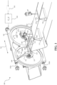
- Figure 1 depicts a cutting device 100 according to the present invention for cutting a food product 111 conveyed by a conveyor means 110 in a direction as indicated by arrow 123.
- the view of the cutting device shown in this embodiment is a view seen from the upstream end of the cutting device (a front view) where the cutting device 100 comprises a first cutting blade 101, a second cutting blade 102, a moving mechanism and a control unit 104.
- the present invention should not be construed as being limited to two cutting blades, but a single cutting blade may just as well be implemented.
- the moving mechanism comprises a frame structure 120 that is slideable attached to parallel tracks 103a,b or similar means such as any type of track means, and where the first and the second cutting blades 101, 102 are, as shown here, rotatable cutting blades that are rigidly attached to frame structure 120 such that the internal distance between the rotational axis 124, 125 of the first and the second cutting blades 101, 102 is fixed at all times having a clockwise 130 and counterclockwise 131 rotational direction.
- the first and the second cutting blades 101, 102 are typically also associated with a motor (not shown here), respectively, on the distal side of the frame structure 120, where the frame structure 120 must thus also carry the motors. Accordingly, the back and forth movement of the cutting blades 101, 102 as indicated by the arrow 112 is thus achieved via back and forth movement of the frame structure 120.
- the frame structure 120 further comprises an opening 126 arranged such that the conveyor means 110 which conveys the food product 111, and a conveyor means 127 that receives the food product after undergoing the cutting process with the first and the second cutting blades 101, 102, are substantially within the same height level within the opening. To ensure that neither of the conveyor means 110 and 127 become damaged, it is of course ensured that the cutting plane of the first and the second cutting blades 101, 102 lies within the space between two conveyor means 110, 127.
- figure 9 shows a schematic zoomed up view of the opening 126 and a position of the conveyors 110, 127 in relation to the opening. Due to the back and forth movement of the frame structure 120 a sufficient side space 901, 902, must be provided between the opening 126 and the conveyors 110, 127 so as to ensure that the frame structure 120 does not collide with the conveyors 110, 127 during the back and forth movement as indicated by the arrow 112.
- the width or in general the dimension of the opening is preferably designed with respect to the width of the conveyors and or the size/shape of the food product 111.
- the frame structure 120 may comprise circular and side by side arranged shaped recessions comprising inner deeper recessions 121b, 122b (or grooves) and outer shallower recessions 121a, 122a in the frame 120 structure, where the outer recessions 121a, 122a have a diameter substantially the same or slightly larger than the diameter of the cutting path of the respective one of the first and the second cutting blades 101, 102.
- the center of the each of the side by side arranged recessions 121, 122 comprises an opening (not shown there) in the center of the recessions through which the rotation axis of the respective one of the first and the second cutting blades 101, 102 extend.
- first and the second cutting blades 101, 102 are shown here as being fully exposed and facing the conveyor 110, which may also be considered as being an infeed conveyor, the cutting blade side may as will be discussed later in relation to figure 10 and 11 be facing conveyor 127, which may also be considered as a take-away conveyor.
- a shield or similar means may be provided in front of the first and the second cutting blades 101, 102 to ensure safety of the operator operating the cutting device.
- the control unit is adapted to move the frame structure back and forth as indicated by arrow 112 and thus move the cutting blades sideways in either direction across the conveyor means sideways in either direction across the conveyor means, while maintaining their internal position fixed, i.e. the distance between the rotational axis of the first and the second cutting blades are fixed.
- Both the first and the second cutting blades 101, 102 are adapted to cut an incision in the product from opposite sides of the food product and the control unit 104 is preferably also adapted to control the first 101, and the second 102 cutting blades independently meaning e.g. that one cutting blade may be performing a cut while the other one is not.
- the food product may in one embodiment, prior to being cut into pieces that are separated from the food product or cut by incisions into parts that are not yet separated from the food product, undergo a cutting process by a cutting means 106, 107, which may be a high pressure water cutter, where at least one cut of the food product has been performed.
- a cutting means 106, 107 which may be a high pressure water cutter, where at least one cut of the food product has been performed.
- the assumption is made that the food product has undergone a cutting process, e.g. by a high pressured water cutter or any other cutting means, and where the cut by the first and the second cutting blades results in a number of pieces that are separated from the food product.
- the at least one cut may be a cut around the pin bones and may also include a further cut extending from the pin bones towards the tail part of the fish fillet. This cut has an angle in relation to an axis extending across the conveyor and perpendicular to the conveying direction.
- the above mentioned controlling of the moving mechanism 103a,b is preferably based on image data 105 that include position related data indicating the position of the at least one cut, e.g. around the pin bones, and where this position related data 105 are utilized as an operation parameter by the control unit 104 for controlling the back and forth placement of the moving mechanism as indicated by arrow 112.
- the cutting means 106, 107 used for performing the at least one cut are positioned above gaps 113, 114, respectively, formed between adjacent elongated supporting means 116a,b, 115a,b, respectively, with a fixed internal arrangement.
- the adjacent elongated supporting means and the cutters 106, 107 which could just as well be a single cutter or more than two cutters, is connected to a control mechanism (not shown) for operating back and forth movement of the adjacent elongated supporting means 116a,b, 115a,b and for operating the cutters 106, 107 across the conveyor 110 perpendicular to the conveying direction while maintaining said internal arrangement of the adjacent elongated supporting means and the cutter fixed.
- the first and said second cutting blades 101, 102 are as shown arranged within the same plane such that the cutting plane is substantially the same. Moreover, the dimension of the blades is preferably such that a distal end 108 of the first cutting blade and a distal end 109 of the second cutting blade, when the distal ends are facing each other, overlap partly. This is to ensure that a cut across the whole food product is possible. Also, to avoid that the cutting blades 101, 102 will come in contact with each other, it is preferred that the cutting blades are adjusted such that when the first and second distal ends 108, 109 are substantially horizontal and are pointing towards each other, one of the distal ends is positioned slightly above the other distal end.
- the rotational movement of the first and the second cutting blades is adjusted such that a phase shift of the first and the second cutting blades is present so as to avoid that the blades collide when the cutting blades are simultaneously in a horizontal position and facing each other.
- Figure 2 shows a zoomed out view of figure 1 , showing in more details the conveyor means where the at least one cut process takes place.
- the food product may be, but is not limited to, a fish fillet such as a cod fillet and where the at least one cut performed by the cutting means 106, 107 may be a cut around the pin bone areas of the cod and where a further cut or cuts may be performed including e.g. a cut extending from the pin bone area towards the tail part of the cod.
- the cutting means 106, 107 may just as well be based on using a single cutting means (not shown) or two or more cutting means.
- the data that operate the cutting means 106, 107 may be X-ray data that originate from an X-ray source (not shown) that depict the bone structure within the food product (the fish fillet).
- FIG 3 shows a cutting system 300 according to the present invention comprising a cutting apparatus 301 such as the one disclosed in WO2013132068 comprising at least one conveyor belt 302, a cutter arranged above a gap (see e.g. figures 1 and 2 ) extending across said at least one conveyor belt where the cutter is positioned in relation to the gap such that the cutting path of the cutter extends through the food products and the gap and below the surface level of said at least one conveyor belt.
- the cutter is adapted to be connected to a control mechanism for operating crosswise movement of the cutter along said gap.
- the cutter and the gap may be similar or identical to the one shown in figures 1 and 2 .
- the gap may be formed by a single conveyor belt as shown in figures 1 and 2 , or via two or more conveyors that are placed adjacent to each other.
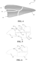
- Figure 4 depicts graphically an example of cuts and incisions in a fish fillet 400 that has undergone a cutting process in e.g. the cutting apparatus 301 shown in figure 3 , where said at least one cut includes cuts around the pin bone area 401 where the loin 403 and the belly 402 and the tail part 404 have been separated from the pin bones 401.
- Figures 5 and 6 depict an example where the fish fillet has undergone a cutting process by the cutting device 100 according to the present invention, where in figure 5 the loin has been cut into three pieces 501-503, i.e. by incisions 508-510 from the loin side and a cut 507 essentially in the longitudinal direction, the belly part has been cut into two pieces 505, 506, i.e. by incisions 511, 512 from the belly side and the cut 507 essentially in the longitudinal direction and the tail is a single piece 504, which is produced by the two incisions 508 and 511 being cut in the fish fillet from each side.
- the loin has in a similar manner been cut into two pieces 601, 602 by the incisions 605, 606, the belly 603 is a single piece and also the tail part 604 is a single piece, provided via the incisions 605.
- Figure 7 depicts graphically a further example of cuts and incisions in a fish fillet that has undergone a cutting process in a cutting apparatus according to an embodiment of the invention.
- the fish fillet has been cut on both sides of the pin bone area and by a cut 704 essentially in the longitudinal direction, which terminates at the loin side of the fish fillet.
- two incisions 701, 702 have been made from the belly side at both ends of a belly part 703 and resulting in two belly parts, one loin part and one tail part. All or almost all of these parts may have been produced to fulfill a pre-defined target criterion or target criteria.
- Figure 8 depicts graphically an even further example of cuts and incisions in a fish fillet that has undergone a cutting process in a cutting apparatus according to an embodiment of the invention.
- the fish fillet has been cut on both sides of the pin bone area and by a cut 807 essentially in the longitudinal direction, which terminates a distance from the tail.
- two incisions 801 have been made from the belly side at both ends of a belly part 803
- two incisions 804, 805 have been made from the loin side at both ends of a loin part 806, resulting in total in two belly parts, two loin part and one tail part. All or almost all of these parts may have been produced to fulfill a pre-defined target criterion or target criteria.
- the incisions from the sides of the fish fillets shown in figures 4-8 may be cut before the at least one cut in the essentially longitudinal direction is being made or vice versa, as it has been explained above.
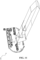
- Figure 10 shows a view seen from the downstream end of a cutting device 1000 according to the present invention for cutting a food product conveyed by a conveyor means 1100 in a direction as indicated by arrow 1230 from a conveyor means 1100
- figure 11 shows a view seen from the upstream end of the cutting device in figure 10 , where the cutting device in figures 10 and 11 is more or less similar as discussed in relation to figures 1 and 2 .
- the cutting device comprises, similarly as discussed in relation to figures 1 and 2 , a first and the second cutting blades 1010, 1020 and a frame structure 1200 that is slideable mounted to at least one rail or track 1200 for supporting the first and the second cutting blades 1010, 1020 in a similar way as discussed in relation to figures 1 and 2 , and where a motor 1001 controlled by a control unit moves the frame structure 1200 and thus the first and the second cutting blades 1010, 1020 in a back and forth movement, similar as already described.
- the food product undergoes one or more cutting processes, e.g. as discussed previously e.g. with one or more high pressure water jets, and where a conveyor means 1270 receives the cut food product, and thus acts in a way as a take-away conveyor.
- the cut food product may e.g. be cut similar as discussed in any of the figures 4-8 .
- the essential difference between the cutting device 1000 shown in figures 10 and 11 and the one shown in figures 1-3 is however the arrangement of the first and the second cutting blades 1010, 1020 and a frame structure 1200, which has been mirrored compared to what figures 1 and 2 shows, i.e. the first and the second cutting blades 1010, 1020 are facing the conveyor means 1270.
- the embodiment shown here further comprise a shield or a cover 1002 for the first and the second cutting blades 1010, 1020, which may also be considered as a guide for first and the second cutting blades 1010, 1020.
- Figure 12 shows a schematic view seen from e.g. the upstream end of a cutting device 2100 according to an embodiment of the present invention for cutting a food product 111 conveyed by a conveyor means 2110, which cutting device 2100 comprises a single cutting blade 2101, i.e. a first cutting blade only.
- the cutting device shown in figure 12 is otherwise more or less similar to the devices as discussed in relation to figures 1 , 2 , 10 and/or 11.
- the cutting device 2100 comprises a frame structure 2120 that is slideable attached to e.g. a pair of parallel tracks 2130a and 2130b, on which it is movable back and forth by means of drive means (not shown in figure 12 ).
- the cutting blade 2101 is rotatably arranged in the frame structure 2120, where the frame structure 2120 may be designed in a manner similar to the frame structure shown in e.g. fig. 1 , i.e. with circular recessions 2121a and 2121b.
- the inner recession 2121b is a deeper recession and the outer recession 2121a is a shallower recession, where the latter has a diameter substantially the same or slightly larger than the rotation diameter of the cutting blade 2101.
- a shield or similar means may be arranged in front of the cutting blade 2101, e.g. a shield having an extent corresponding to the recession 2121a and possibly part of the recession 2121b, to ensure safety of the operator operating the cutting device 2100.
- the frame structure 2120 comprises an opening 2126, which is arranged such that the food products 111 and conveyor means for the food products 111 do not interfere with the frame structure during the back and forth movement of the frame structure 2120 and during the conveying and cutting of the food products 111.
- the respective conveyor means for the food products 111 in the area of the opening 2126 comprises the conveyor 2110 as shown in fig. 12 for conveying the food products 111 to the cutting device and a receiving conveyor (not shown in fig 12 ) for the cut food products, which conveyors are arranged substantially at the same level within the opening and with a gap between the conveyor ends, which is sufficiently large for the cutting blade 2101 to pass through.
- the single cutting blade 2101 is as mentioned rotatably arranged as indicated with the arrow 2130, and a drive motor 2200 may be arranged at the frame structure 2120 for operating the cutting blade 2101.
- the cutting blade 2101 is adapted for cutting an incision in the food product 111 from the side of the product, controlled by a control unit (not shown in fig. 12 ) and based on e.g. image data including position related data (cf. e.g. fig. 1 ).
- the control unit may further be adapted for controlling the back and forth movement of the frame structure.
- the frame structure 2120 is controlled by the control unit to adjust its position across the conveyor means to correspond to the intended length of the incision in the food product and the cutting blade 2101 is controlled to, operated by the drive motor 2200, to cut the incision in the food product 111 at a time corresponding to the position of the intended incision along the length of the food product 111 in the conveying direction.
- further cuts may be made in addition to the one or more incisions made from one side of the food product 111 such as e.g. cuts made essentially in the longitudinal direction of the food product, for example cuts made prior to the cut(s) made by the cutting device 2100 or subsequently to the cut(s) made by the cutting device 2100, e.g. cuts made by a high pressure water jet cutter or the like.
Landscapes
- Engineering & Computer Science (AREA)
- Life Sciences & Earth Sciences (AREA)
- Forests & Forestry (AREA)
- Mechanical Engineering (AREA)
- Wood Science & Technology (AREA)
- Zoology (AREA)
- Food Science & Technology (AREA)
- Computer Vision & Pattern Recognition (AREA)
- Processing Of Meat And Fish (AREA)
- Meat, Egg Or Seafood Products (AREA)
- Formation And Processing Of Food Products (AREA)
Claims (15)
- Dispositif de découpe servant à découper un produit alimentaire (111) qui est transporté par un moyen transporteur (110 ; 1100 ; 2110), le dispositif de découpe comprenant :• une première lame de découpe (101 ; 1010 ; 2101), qui est une lame de découpe rotative,• un moteur servant à actionner la lame de découpe rotative, et• une unité de commande (104),dans lequel le dispositif de découpe comprend en outre• un mécanisme de déplacement fixé à ladite première lame de découpe (101 ; 1010 ; 2101) pour déplacer la première lame de découpe latéralement dans l'une ou l'autre direction sur l'ensemble du moyen transporteur (110 ; 1100 ; 2110),caractérisé en ce que ladite première lame de découpe (101 ; 1010 ; 2101) est conçue pour faire au moins une incision dans le produit (111) depuis un côté du produit,dans lequel ladite unité de commande (104) est conçue pour commander ladite première lame de découpe (101 ; 1010 ; 2101) et ledit mécanisme de déplacement sur la base de données d'image (105) dudit produit alimentaire, y compris de l'utilisation desdites données d'image pour donner pour instruction audit mécanisme de déplacement d'ajuster la position de ladite première lame de découpe (101 ; 1010 ; 2101) sur l'ensemble dudit moyen transporteur (110 ; 1100 ; 2110).
- Dispositif de découpe selon la revendication 1, comprenant en outre une seconde lame de découpe (102 ; 1020) conçue pour faire au moins une incision dans le produit (111) depuis un côté opposé au côté de la première lame de découpe (101 ; 1010), et dans lequel l'unité de commande (104) est en outre conçue pour commander la seconde lame de découpe (102 ; 1020).
- Dispositif de découpe selon la revendication 1 ou 2, dans lequel, avant d'être muni d'une ou de plusieurs incisions, ledit produit alimentaire (111) a subi un processus de découpe dans lequel au moins une découpe (507 ; 704 ; 807) du produit alimentaire a été effectuée avec un angle par rapport à un axe s'étendant sur l'ensemble du transporteur et perpendiculaire à la direction de transport, dans lequel l'ajustement du mécanisme de déplacement comprend l'ajustement de la position d'au moins ladite première lame de découpe (101 ; 1010 ; 2101) sur l'ensemble dudit moyen transporteur (110 ; 1100 ; 2110) de telle sorte qu'il suit ladite au moins une découpe (507 ; 704 ; 807) du produit alimentaire.
- Dispositif de découpe selon la revendication 2, dans lequel ladite seconde lame de découpe (102 ; 1020) est en outre fixé audit mécanisme de déplacement de telle sorte que les première (101 ; 1010) et seconde lames de découpe (102 ; 1020) sont déplacés latéralement dans l'une ou l'autre direction sur l'ensemble du moyen transporteur (110 ; 1100) tandis que la position interne desdites première et seconde lames de découpe est maintenue fixe.
- Dispositif de découpe selon l'une quelconque des revendications précédentes, dans lequel la commande par ladite unité de commande (104) comprend en outre l'actionnement des première (101 ; 1010) et seconde lames de découpe (102 ; 1020) indépendamment.
- Dispositif de découpe selon l'une quelconque des revendications précédentes, dans lequel ladite première (101 ; 1010) et ladite seconde lame de découpe (102 ; 1020) sont agencées dans le même plan de telle sorte que le plan de découpe est sensiblement le même, dans lequel une extrémité distale (108) de ladite première lame de découpe et une extrémité distale (109) de ladite seconde lame de découpe se chevauchent partiellement lorsque lesdites extrémités distales se font mutuellement face.
- Dispositif de découpe selon la revendication 6, dans lequel le mouvement de rotation des première (101 ; 1010) et seconde lames de découpe (102 ; 1020) est ajusté de telle sorte qu'un décalage des première et seconde lames de découpe est présent de façon à éviter une collision des première et seconde lames de découpe lorsque les lames de découpe sont simultanément dans une position horizontale et en face l'une de l'autre.
- Procédé de découpe d'un produit alimentaire (111) transporté par un moyen transporteur (110 ; 1100 ; 2110) en morceaux à l'aide d'un dispositif de découpe qui comprend :• une première lame de découpe (101 ; 1010 ; 2101), qui est une lame de découpe rotative,• un moteur servant à actionner la lame de découpe rotative, et• une unité de commande (104),dans lequel le dispositif de découpe comprend en outre• un mécanisme de déplacement fixé à ladite première lame de découpe (101 ; 1010 ; 2101) pour déplacer la première lame de découpe latéralement dans l'une ou l'autre direction sur l'ensemble du moyen transporteur,caractérisé en ce que ladite première lame de découpe (101 ; 1010 ; 2101) est conçue pour faire au moins une incision dans le produit alimentaire (111) depuis un côté du produit,dans lequel ladite unité de commande (104) est conçue pour commander ladite première lame de découpe (101 ; 1010 ; 2101) et ledit mécanisme de déplacement sur la base de données d'image (105) dudit produit alimentaire, y compris l'utilisation desdites données d'image (105) pour donner pour instruction audit mécanisme de déplacement d'ajuster la position de ladite première lame de découpe (101 ; 1010 ; 2101) sur l'ensemble dudit moyen transporteur (110 ; 1100 ; 2110).
- Procédé selon la revendication 8, dans lequel le dispositif de découpe comprend en outre une seconde lame de découpe (102 ; 1020) conçue pour faire au moins une incision dans le produit depuis un côté opposé au côté de la première lame de découpe (101 ; 1010), et dans lequel l'unité de commande (104) est en outre conçue pour commander la seconde lame de découpe.
- Procédé selon la revendication 8 ou 9, dans lequel, avant d'être muni d'une ou de plusieurs incisions, ledit produit alimentaire (111) a subi un processus de découpe dans lequel au moins une découpe (507 ; 704 ; 807) du produit alimentaire a été effectuée avec un angle par rapport à un axe s'étendant sur l'ensemble du transporteur et perpendiculaire à la direction de transport, dans lequel l'ajustement du mécanisme de déplacement comprend l'ajustement de la position d'au moins ladite première lame de découpe (101 ; 1010 ; 2101) sur l'ensemble dudit moyen transporteur (110 ; 1100 ; 2110) de telle sorte qu'il suit ladite au moins une découpe (507 ; 704 ; 807) du produit alimentaire.
- Procédé selon l'une quelconque des revendications 8 à 10, dans lequel les produits alimentaires sont des filets de poisson (400) et dans lequel l'au moins une découpe (507 ; 704 ; 807) comporte des découpes autour des arêtes (401) dans le filet de poisson.
- Procédé selon la revendication 11, dans lequel l'au moins une découpe (507 ; 704 ; 807) comporte en outre une découpe s'étendant le long du filet de poisson depuis les arêtes (401) et au moins partiellement vers la partie queue (404 ; 504 ; 604) du filet de poisson.
- Procédé selon l'une quelconque des revendications 8 à 12, dans lequel la découpe du produit alimentaire comprend la découpe de morceaux de produits alimentaires ou la découpe du produit alimentaire avec des parties entre les incisions (508, 509, 510, 511, 512 ; 605, 606 ; 701, 702 ; 801, 804, 805) pour avoir une cible fixe telle qu'une cible de poids fixe.
- Système de découpe servant à découper un produit alimentaire (111) transporté par un moyen transporteur (110 ; 1100 ; 2110), comprenant :• un système d'imagerie,• un dispositif de découpe (100 ; 1000 ; 2100) comprenant :∘ une première lame de découpe (101 ; 1010 ; 2101), qui est une lame de découpe rotative,∘ un moteur servant à actionner la lame de découpe rotative, et∘ une unité de commande (104),dans lequel le dispositif de découpe comprend en outre∘ un mécanisme de déplacement fixé à ladite première lame de découpe (101 ; 1010 ; 2101) pour déplacer la première lame de découpe latéralement dans l'une ou l'autre direction sur l'ensemble du moyen transporteur (110 ; 1100 ; 2110),caractérisé en ce que ladite première lame de découpe est conçue pour faire au moins une incision dans le produit (111) depuis un côté du produit,dans lequel ladite unité de commande (104) est conçue pour commander ladite première lame de découpe (101 ; 1010 ; 2101) et ledit mécanisme de déplacement sur la base de données d'image (105) dudit produit alimentaire, y compris de l'utilisation desdites données d'image pour donner pour instruction audit mécanisme de déplacement d'ajuster la position de ladite première lame de découpe (101 ; 1010 ; 2101) sur l'ensemble dudit moyen transporteur (110 ; 1100 ; 2110).
- Système de découpe selon la revendication 14, comprenant en outre :• une seconde lame de découpe (102 ; 1020) conçue pour faire au moins une incision dans le produit (111) depuis un côté opposé au côté de la première lame de découpe (101 ; 1010), et dans lequel l'unité de commande (104) est en outre conçue pour commander la seconde lame de découpe (102 ; 1020),• un mécanisme de découpe (106, 107) actionné par l'unité de commande (104) pour effectuer au moins une découpe (507 ; 704 ; 807) du produit alimentaire avec un angle par rapport à un axe s'étendant sur l'ensemble du transporteur et perpendiculaire à la direction de transport, dans lequel l'ajustement du mécanisme de déplacement comprend l'ajustement de la position d'au moins ladite première lame de découpe (101 ; 1010 ; 2101) sur l'ensemble dudit moyen transporteur (110 ; 1100 ; 2110) de telle sorte qu'il suit ladite au moins une découpe (507 ; 704 ; 807) du produit alimentaire.
Applications Claiming Priority (3)
| Application Number | Priority Date | Filing Date | Title |
|---|---|---|---|
| DKPA201470829 | 2014-12-23 | ||
| DK201570224A DK201570224A1 (en) | 2015-04-16 | 2015-04-16 | A cutting device and a cutting system for cutting food products |
| PCT/EP2015/080934 WO2016102542A1 (fr) | 2014-12-23 | 2015-12-22 | Dispositif et système de coupe pour la coupe de produits alimentaires |
Publications (2)
| Publication Number | Publication Date |
|---|---|
| EP3236757A1 EP3236757A1 (fr) | 2017-11-01 |
| EP3236757B1 true EP3236757B1 (fr) | 2024-03-13 |
Family
ID=54884074
Family Applications (1)
| Application Number | Title | Priority Date | Filing Date |
|---|---|---|---|
| EP15813084.9A Active EP3236757B1 (fr) | 2014-12-23 | 2015-12-22 | Dispositif et système de coupe pour la coupe de produits alimentaires |
Country Status (6)
| Country | Link |
|---|---|
| US (1) | US10555539B2 (fr) |
| EP (1) | EP3236757B1 (fr) |
| AU (1) | AU2015371036C1 (fr) |
| BR (1) | BR112017013652B1 (fr) |
| DK (1) | DK3236757T3 (fr) |
| WO (1) | WO2016102542A1 (fr) |
Families Citing this family (2)
| Publication number | Priority date | Publication date | Assignee | Title |
|---|---|---|---|---|
| WO2020165234A1 (fr) * | 2019-02-12 | 2020-08-20 | Marel A/S | Commande de la vitesse angulaire d'un mouvement excentrique d'une lame circulaire |
| WO2020227692A1 (fr) * | 2019-05-08 | 2020-11-12 | Dragt Steven Richard | Dispositif de coupe intelligent pour traitement de produits à grande vitesse |
Family Cites Families (17)
| Publication number | Priority date | Publication date | Assignee | Title |
|---|---|---|---|---|
| US3982299A (en) * | 1975-05-01 | 1976-09-28 | Burns Foods Limited | Meat cutter |
| GB1594101A (en) * | 1977-06-20 | 1981-07-30 | Haverhill Meat Prod Ltd | Meat cutting apparatus |
| US4557019A (en) * | 1984-08-10 | 1985-12-10 | Seafreeze Limited Partnership | Automatic portion-cutting method and machine |
| US4875254A (en) * | 1988-03-22 | 1989-10-24 | Design Systems, Inc. | Method and apparatus for automatically cutting food products to predetermined weight or shape |
| NL9001240A (nl) * | 1990-05-31 | 1991-12-16 | Meyn Bv | Inrichting voor het bewerken van platvis. |
| US5163865A (en) * | 1991-05-08 | 1992-11-17 | Innerspace Technologies Of Alaska, Inc. | Method and apparatus for processing fish fillets and other food items into predetermined portions |
| CA2200545C (fr) * | 1997-03-20 | 2003-01-07 | Didier Conte | Appareil et methode permettant d'enlever des cotes |
| US6882434B1 (en) * | 1999-04-20 | 2005-04-19 | Formax, Inc. | Automated product profiling apparatus and product slicing system using same |
| WO2004106020A1 (fr) | 2003-06-03 | 2004-12-09 | Scanvaegt International A/S | Appareil et procede de decoupage de portions de produits alimentaires |
| JP4126027B2 (ja) * | 2004-04-16 | 2008-07-30 | 食肉生産技術研究組合 | 脊柱除去方法および脊柱除去装置 |
| IS7959A (is) * | 2004-12-16 | 2006-06-17 | Skaginn Hf. | Athferth og bunathur vith sj βlfvirka beingarthst”ku, skurth meth vatni og snyrtingu β afurth |
| US8688267B2 (en) * | 2004-12-30 | 2014-04-01 | John Bean Technologies Corporation | Classifying workpieces to be portioned into various end products to optimally meet overall production goals |
| AU2005248939B2 (en) * | 2004-12-30 | 2011-10-27 | John Bean Technologies Corporation | Portioning apparatus and method |
| US8096860B2 (en) * | 2009-05-29 | 2012-01-17 | Cargill, Incorporated | Automated meat breaking system and method |
| EP2353395A1 (fr) * | 2010-02-07 | 2011-08-10 | Valka Ehf | Appareil de traitement des aliments pour détecter et découper les tissus des articles alimentaires |
| EP2636495A1 (fr) | 2012-03-08 | 2013-09-11 | Marel Iceland EHF | Appareil de découpe permettant de couper des articles alimentaires transportés sur un convoyeur comprenant au moins une bande transporteuse ainsi que système de traitement de produits alimentaires comprenant un tel appareil |
| DK2986427T3 (en) * | 2013-04-19 | 2018-02-26 | Marel As | A CUTTER FOR CUTTING FOOD ITEMS |
-
2015
- 2015-12-22 US US15/539,446 patent/US10555539B2/en active Active
- 2015-12-22 BR BR112017013652-0A patent/BR112017013652B1/pt active IP Right Grant
- 2015-12-22 AU AU2015371036A patent/AU2015371036C1/en active Active
- 2015-12-22 DK DK15813084.9T patent/DK3236757T3/da active
- 2015-12-22 WO PCT/EP2015/080934 patent/WO2016102542A1/fr active Application Filing
- 2015-12-22 EP EP15813084.9A patent/EP3236757B1/fr active Active
Also Published As
| Publication number | Publication date |
|---|---|
| BR112017013652B1 (pt) | 2022-01-25 |
| BR112017013652A2 (pt) | 2018-03-06 |
| NZ733368A (en) | 2021-11-26 |
| WO2016102542A1 (fr) | 2016-06-30 |
| US20180084793A1 (en) | 2018-03-29 |
| AU2015371036B2 (en) | 2021-03-18 |
| DK3236757T3 (da) | 2024-05-27 |
| AU2015371036C1 (en) | 2021-09-16 |
| AU2015371036A1 (en) | 2017-07-20 |
| US10555539B2 (en) | 2020-02-11 |
| EP3236757A1 (fr) | 2017-11-01 |
Similar Documents
| Publication | Publication Date | Title |
|---|---|---|
| US20200282585A1 (en) | Cutting apparatus for cutting food items conveyed on a conveyor including at least one conveyor belt | |
| JP6521998B2 (ja) | 食品製品を切断してより小さい食品製品にする切断機及び方法 | |
| US11051522B2 (en) | Cutting system for cutting food products | |
| AU2008324430B2 (en) | Device for extracting the flank bones of beheaded, slaughtered fish having open abdominal cavities and filleting machine for filleting beheaded, slaughtered fish having open abdominal cavities comprising such a device | |
| EP3169161B1 (fr) | Système et procédé de retrait d'arêtes | |
| US20170259448A1 (en) | Slicing device | |
| CN103702567A (zh) | 从去内脏的家禽屠体上分离叉骨的装置及方法 | |
| EP3236757B1 (fr) | Dispositif et système de coupe pour la coupe de produits alimentaires | |
| EP3432724B1 (fr) | Système pour séparer la viande de poitrine d'au moins une partie d'un bréchet d'une partie de carcasse de volaille abattue | |
| US20200329723A1 (en) | Apparatus for cutting fish fillets from flank bones, filleting apparatus with such an appatatus, and method for cutting fish fillets from flank bones | |
| DK201570224A1 (en) | A cutting device and a cutting system for cutting food products | |
| NZ733368B2 (en) | A cutting device and a cutting system for cutting food products | |
| US20120190285A1 (en) | Poultry Wing Cutter for Narrow Pitch Poultry Lines | |
| EP3405319B1 (fr) | Dispositif pour la découpe des alliments | |
| US20240180178A1 (en) | A machine for filleting fish | |
| DK2664240T3 (en) | scratch machine |
Legal Events
| Date | Code | Title | Description |
|---|---|---|---|
| STAA | Information on the status of an ep patent application or granted ep patent |
Free format text: STATUS: THE INTERNATIONAL PUBLICATION HAS BEEN MADE |
|
| PUAI | Public reference made under article 153(3) epc to a published international application that has entered the european phase |
Free format text: ORIGINAL CODE: 0009012 |
|
| STAA | Information on the status of an ep patent application or granted ep patent |
Free format text: STATUS: REQUEST FOR EXAMINATION WAS MADE |
|
| 17P | Request for examination filed |
Effective date: 20170612 |
|
| AK | Designated contracting states |
Kind code of ref document: A1 Designated state(s): AL AT BE BG CH CY CZ DE DK EE ES FI FR GB GR HR HU IE IS IT LI LT LU LV MC MK MT NL NO PL PT RO RS SE SI SK SM TR |
|
| AX | Request for extension of the european patent |
Extension state: BA ME |
|
| DAV | Request for validation of the european patent (deleted) | ||
| DAX | Request for extension of the european patent (deleted) | ||
| STAA | Information on the status of an ep patent application or granted ep patent |
Free format text: STATUS: EXAMINATION IS IN PROGRESS |
|
| 17Q | First examination report despatched |
Effective date: 20210412 |
|
| STAA | Information on the status of an ep patent application or granted ep patent |
Free format text: STATUS: EXAMINATION IS IN PROGRESS |
|
| GRAP | Despatch of communication of intention to grant a patent |
Free format text: ORIGINAL CODE: EPIDOSNIGR1 |
|
| STAA | Information on the status of an ep patent application or granted ep patent |
Free format text: STATUS: GRANT OF PATENT IS INTENDED |
|
| INTG | Intention to grant announced |
Effective date: 20231004 |
|
| GRAS | Grant fee paid |
Free format text: ORIGINAL CODE: EPIDOSNIGR3 |
|
| GRAA | (expected) grant |
Free format text: ORIGINAL CODE: 0009210 |
|
| STAA | Information on the status of an ep patent application or granted ep patent |
Free format text: STATUS: THE PATENT HAS BEEN GRANTED |
|
| AK | Designated contracting states |
Kind code of ref document: B1 Designated state(s): AL AT BE BG CH CY CZ DE DK EE ES FI FR GB GR HR HU IE IS IT LI LT LU LV MC MK MT NL NO PL PT RO RS SE SI SK SM TR |
|
| P01 | Opt-out of the competence of the unified patent court (upc) registered |
Effective date: 20240206 |
|
| REG | Reference to a national code |
Ref country code: GB Ref legal event code: FG4D |
|
| REG | Reference to a national code |
Ref country code: CH Ref legal event code: EP |
|
| REG | Reference to a national code |
Ref country code: DE Ref legal event code: R096 Ref document number: 602015087929 Country of ref document: DE |
|
| REG | Reference to a national code |
Ref country code: IE Ref legal event code: FG4D |
|
| REG | Reference to a national code |
Ref country code: DK Ref legal event code: T3 Effective date: 20240522 |