EP3236643A1 - Dispositif de transmission de contenu et terminal mobile - Google Patents
Dispositif de transmission de contenu et terminal mobile Download PDFInfo
- Publication number
- EP3236643A1 EP3236643A1 EP17167017.7A EP17167017A EP3236643A1 EP 3236643 A1 EP3236643 A1 EP 3236643A1 EP 17167017 A EP17167017 A EP 17167017A EP 3236643 A1 EP3236643 A1 EP 3236643A1
- Authority
- EP
- European Patent Office
- Prior art keywords
- content
- transmission device
- controller
- mobile terminal
- reception device
- Prior art date
- Legal status (The legal status is an assumption and is not a legal conclusion. Google has not performed a legal analysis and makes no representation as to the accuracy of the status listed.)
- Granted
Links
- 230000005540 biological transmission Effects 0.000 title claims abstract description 301
- 238000004891 communication Methods 0.000 claims abstract description 77
- 230000004044 response Effects 0.000 claims abstract description 57
- 230000008859 change Effects 0.000 claims description 6
- 230000033001 locomotion Effects 0.000 description 25
- 238000012545 processing Methods 0.000 description 24
- 230000006870 function Effects 0.000 description 17
- 238000010586 diagram Methods 0.000 description 16
- 238000000034 method Methods 0.000 description 15
- 230000005236 sound signal Effects 0.000 description 13
- 238000012546 transfer Methods 0.000 description 8
- 230000008569 process Effects 0.000 description 7
- 239000002131 composite material Substances 0.000 description 6
- 230000000694 effects Effects 0.000 description 5
- 230000001133 acceleration Effects 0.000 description 3
- 238000010295 mobile communication Methods 0.000 description 3
- 206010044565 Tremor Diseases 0.000 description 2
- 230000009471 action Effects 0.000 description 2
- 230000008901 benefit Effects 0.000 description 2
- 239000011521 glass Substances 0.000 description 2
- 230000006386 memory function Effects 0.000 description 2
- 238000012986 modification Methods 0.000 description 2
- 230000004048 modification Effects 0.000 description 2
- 230000003287 optical effect Effects 0.000 description 2
- 238000013500 data storage Methods 0.000 description 1
- 238000005516 engineering process Methods 0.000 description 1
- 239000000284 extract Substances 0.000 description 1
- 230000005484 gravity Effects 0.000 description 1
- 238000007726 management method Methods 0.000 description 1
- 239000000203 mixture Substances 0.000 description 1
- 230000003068 static effect Effects 0.000 description 1
- 231100001122 three-band system Toxicity 0.000 description 1
Images


Classifications
-
- H—ELECTRICITY
- H04—ELECTRIC COMMUNICATION TECHNIQUE
- H04M—TELEPHONIC COMMUNICATION
- H04M1/00—Substation equipment, e.g. for use by subscribers
- H04M1/72—Mobile telephones; Cordless telephones, i.e. devices for establishing wireless links to base stations without route selection
- H04M1/724—User interfaces specially adapted for cordless or mobile telephones
- H04M1/72403—User interfaces specially adapted for cordless or mobile telephones with means for local support of applications that increase the functionality
- H04M1/72442—User interfaces specially adapted for cordless or mobile telephones with means for local support of applications that increase the functionality for playing music files
-
- G—PHYSICS
- G06—COMPUTING; CALCULATING OR COUNTING
- G06F—ELECTRIC DIGITAL DATA PROCESSING
- G06F3/00—Input arrangements for transferring data to be processed into a form capable of being handled by the computer; Output arrangements for transferring data from processing unit to output unit, e.g. interface arrangements
- G06F3/01—Input arrangements or combined input and output arrangements for interaction between user and computer
- G06F3/048—Interaction techniques based on graphical user interfaces [GUI]
- G06F3/0481—Interaction techniques based on graphical user interfaces [GUI] based on specific properties of the displayed interaction object or a metaphor-based environment, e.g. interaction with desktop elements like windows or icons, or assisted by a cursor's changing behaviour or appearance
- G06F3/0482—Interaction with lists of selectable items, e.g. menus
-
- H—ELECTRICITY
- H04—ELECTRIC COMMUNICATION TECHNIQUE
- H04M—TELEPHONIC COMMUNICATION
- H04M1/00—Substation equipment, e.g. for use by subscribers
- H04M1/72—Mobile telephones; Cordless telephones, i.e. devices for establishing wireless links to base stations without route selection
- H04M1/724—User interfaces specially adapted for cordless or mobile telephones
- H04M1/72403—User interfaces specially adapted for cordless or mobile telephones with means for local support of applications that increase the functionality
- H04M1/72409—User interfaces specially adapted for cordless or mobile telephones with means for local support of applications that increase the functionality by interfacing with external accessories
- H04M1/72412—User interfaces specially adapted for cordless or mobile telephones with means for local support of applications that increase the functionality by interfacing with external accessories using two-way short-range wireless interfaces
-
- G—PHYSICS
- G06—COMPUTING; CALCULATING OR COUNTING
- G06F—ELECTRIC DIGITAL DATA PROCESSING
- G06F3/00—Input arrangements for transferring data to be processed into a form capable of being handled by the computer; Output arrangements for transferring data from processing unit to output unit, e.g. interface arrangements
- G06F3/01—Input arrangements or combined input and output arrangements for interaction between user and computer
- G06F3/048—Interaction techniques based on graphical user interfaces [GUI]
-
- G—PHYSICS
- G08—SIGNALLING
- G08C—TRANSMISSION SYSTEMS FOR MEASURED VALUES, CONTROL OR SIMILAR SIGNALS
- G08C17/00—Arrangements for transmitting signals characterised by the use of a wireless electrical link
- G08C17/02—Arrangements for transmitting signals characterised by the use of a wireless electrical link using a radio link
-
- H—ELECTRICITY
- H04—ELECTRIC COMMUNICATION TECHNIQUE
- H04M—TELEPHONIC COMMUNICATION
- H04M1/00—Substation equipment, e.g. for use by subscribers
- H04M1/72—Mobile telephones; Cordless telephones, i.e. devices for establishing wireless links to base stations without route selection
- H04M1/724—User interfaces specially adapted for cordless or mobile telephones
- H04M1/72403—User interfaces specially adapted for cordless or mobile telephones with means for local support of applications that increase the functionality
- H04M1/72409—User interfaces specially adapted for cordless or mobile telephones with means for local support of applications that increase the functionality by interfacing with external accessories
- H04M1/72415—User interfaces specially adapted for cordless or mobile telephones with means for local support of applications that increase the functionality by interfacing with external accessories for remote control of appliances
-
- H—ELECTRICITY
- H04—ELECTRIC COMMUNICATION TECHNIQUE
- H04M—TELEPHONIC COMMUNICATION
- H04M1/00—Substation equipment, e.g. for use by subscribers
- H04M1/72—Mobile telephones; Cordless telephones, i.e. devices for establishing wireless links to base stations without route selection
- H04M1/724—User interfaces specially adapted for cordless or mobile telephones
- H04M1/72403—User interfaces specially adapted for cordless or mobile telephones with means for local support of applications that increase the functionality
- H04M1/7243—User interfaces specially adapted for cordless or mobile telephones with means for local support of applications that increase the functionality with interactive means for internal management of messages
- H04M1/72439—User interfaces specially adapted for cordless or mobile telephones with means for local support of applications that increase the functionality with interactive means for internal management of messages for image or video messaging
-
- H—ELECTRICITY
- H04—ELECTRIC COMMUNICATION TECHNIQUE
- H04N—PICTORIAL COMMUNICATION, e.g. TELEVISION
- H04N21/00—Selective content distribution, e.g. interactive television or video on demand [VOD]
- H04N21/40—Client devices specifically adapted for the reception of or interaction with content, e.g. set-top-box [STB]; Operations thereof
- H04N21/41—Structure of client; Structure of client peripherals
- H04N21/4104—Peripherals receiving signals from specially adapted client devices
- H04N21/4126—The peripheral being portable, e.g. PDAs or mobile phones
- H04N21/41265—The peripheral being portable, e.g. PDAs or mobile phones having a remote control device for bidirectional communication between the remote control device and client device
-
- H—ELECTRICITY
- H04—ELECTRIC COMMUNICATION TECHNIQUE
- H04N—PICTORIAL COMMUNICATION, e.g. TELEVISION
- H04N21/00—Selective content distribution, e.g. interactive television or video on demand [VOD]
- H04N21/40—Client devices specifically adapted for the reception of or interaction with content, e.g. set-top-box [STB]; Operations thereof
- H04N21/41—Structure of client; Structure of client peripherals
- H04N21/422—Input-only peripherals, i.e. input devices connected to specially adapted client devices, e.g. global positioning system [GPS]
- H04N21/42204—User interfaces specially adapted for controlling a client device through a remote control device; Remote control devices therefor
- H04N21/42206—User interfaces specially adapted for controlling a client device through a remote control device; Remote control devices therefor characterized by hardware details
- H04N21/4222—Remote control device emulator integrated into a non-television apparatus, e.g. a PDA, media center or smart toy
-
- H—ELECTRICITY
- H04—ELECTRIC COMMUNICATION TECHNIQUE
- H04N—PICTORIAL COMMUNICATION, e.g. TELEVISION
- H04N21/00—Selective content distribution, e.g. interactive television or video on demand [VOD]
- H04N21/40—Client devices specifically adapted for the reception of or interaction with content, e.g. set-top-box [STB]; Operations thereof
- H04N21/41—Structure of client; Structure of client peripherals
- H04N21/422—Input-only peripherals, i.e. input devices connected to specially adapted client devices, e.g. global positioning system [GPS]
- H04N21/42204—User interfaces specially adapted for controlling a client device through a remote control device; Remote control devices therefor
- H04N21/42206—User interfaces specially adapted for controlling a client device through a remote control device; Remote control devices therefor characterized by hardware details
- H04N21/42224—Touch pad or touch panel provided on the remote control
-
- H—ELECTRICITY
- H04—ELECTRIC COMMUNICATION TECHNIQUE
- H04N—PICTORIAL COMMUNICATION, e.g. TELEVISION
- H04N21/00—Selective content distribution, e.g. interactive television or video on demand [VOD]
- H04N21/40—Client devices specifically adapted for the reception of or interaction with content, e.g. set-top-box [STB]; Operations thereof
- H04N21/43—Processing of content or additional data, e.g. demultiplexing additional data from a digital video stream; Elementary client operations, e.g. monitoring of home network or synchronising decoder's clock; Client middleware
- H04N21/431—Generation of visual interfaces for content selection or interaction; Content or additional data rendering
- H04N21/4312—Generation of visual interfaces for content selection or interaction; Content or additional data rendering involving specific graphical features, e.g. screen layout, special fonts or colors, blinking icons, highlights or animations
-
- H—ELECTRICITY
- H04—ELECTRIC COMMUNICATION TECHNIQUE
- H04N—PICTORIAL COMMUNICATION, e.g. TELEVISION
- H04N21/00—Selective content distribution, e.g. interactive television or video on demand [VOD]
- H04N21/40—Client devices specifically adapted for the reception of or interaction with content, e.g. set-top-box [STB]; Operations thereof
- H04N21/43—Processing of content or additional data, e.g. demultiplexing additional data from a digital video stream; Elementary client operations, e.g. monitoring of home network or synchronising decoder's clock; Client middleware
- H04N21/436—Interfacing a local distribution network, e.g. communicating with another STB or one or more peripheral devices inside the home
- H04N21/43615—Interfacing a Home Network, e.g. for connecting the client to a plurality of peripherals
-
- G—PHYSICS
- G08—SIGNALLING
- G08C—TRANSMISSION SYSTEMS FOR MEASURED VALUES, CONTROL OR SIMILAR SIGNALS
- G08C2201/00—Transmission systems of control signals via wireless link
- G08C2201/30—User interface
- G08C2201/32—Remote control based on movements, attitude of remote control device
-
- G—PHYSICS
- G08—SIGNALLING
- G08C—TRANSMISSION SYSTEMS FOR MEASURED VALUES, CONTROL OR SIMILAR SIGNALS
- G08C23/00—Non-electrical signal transmission systems, e.g. optical systems
- G08C23/02—Non-electrical signal transmission systems, e.g. optical systems using infrasonic, sonic or ultrasonic waves
-
- H—ELECTRICITY
- H04—ELECTRIC COMMUNICATION TECHNIQUE
- H04M—TELEPHONIC COMMUNICATION
- H04M2201/00—Electronic components, circuits, software, systems or apparatus used in telephone systems
- H04M2201/34—Microprocessors
-
- H—ELECTRICITY
- H04—ELECTRIC COMMUNICATION TECHNIQUE
- H04M—TELEPHONIC COMMUNICATION
- H04M2201/00—Electronic components, circuits, software, systems or apparatus used in telephone systems
- H04M2201/38—Displays
-
- H—ELECTRICITY
- H04—ELECTRIC COMMUNICATION TECHNIQUE
- H04M—TELEPHONIC COMMUNICATION
- H04M2250/00—Details of telephonic subscriber devices
- H04M2250/06—Details of telephonic subscriber devices including a wireless LAN interface
-
- H—ELECTRICITY
- H04—ELECTRIC COMMUNICATION TECHNIQUE
- H04N—PICTORIAL COMMUNICATION, e.g. TELEVISION
- H04N21/00—Selective content distribution, e.g. interactive television or video on demand [VOD]
- H04N21/40—Client devices specifically adapted for the reception of or interaction with content, e.g. set-top-box [STB]; Operations thereof
- H04N21/41—Structure of client; Structure of client peripherals
- H04N21/422—Input-only peripherals, i.e. input devices connected to specially adapted client devices, e.g. global positioning system [GPS]
Definitions
- the present invention relates to a content transmission device and a mobile terminal, and more particularly to a content transmission device and a mobile terminal that is capable of easily performing the transmission of content from the content transmission device.
- a mobile terminal is a portable device having one or more functions, such as a function of performing voice and video communications, a function of inputting and outputting information, and a function of storing data.
- the mobile terminal has come to have complex functions, such as a function of taking still pictures or motion pictures, a function of playing music files or video files, a function of playing games, a function of receiving broadcasts, a function of providing wireless Internet access, and a function of transmitting and receiving messages.
- the mobile terminal has been realized in the form of a total multimedia player.
- Various attempts based on hardware or software have been made in order for the mobile terminal realized in the form of the multimedia player to have increasingly complex functions.
- a mobile terminal including a display unit, a communication unit to transmit a control signal to a content transmission device, and a controller to display a content playback setting screen, including an item related to at least one content reception device, an item related to at least one input terminal through which the at least one content reception device is connected to the content transmission device, and a thumbnail image corresponding to the item related to the at least one input terminal, in response to an input for the execution of a content playback application, wherein the controller performs a control operation to transmit content data received through a first input terminal of the content transmission device to a first content reception device based on the selection of the first content reception device from among the at least one content reception device and the selection of the first input terminal from among the at least one input terminal.
- a content transmission device including a communication unit to exchange data with a mobile terminal, an interface unit having a plurality of input terminals to receive content data from a plurality of external devices, and a controller to perform a control operation to, when receiving, from the mobile terminal, transmit a remote control signal in response to the selection of a first content reception device from among at least one content reception device and the selection of a first input terminal from among the input terminals, content data received through the first input terminal of the content transmission device to the first content reception device.
- module and “unit,” when attached to the names of components, are used herein to help the understanding of the components and thus they should not be considered as having specific meanings or roles. Accordingly, the terms “module” and “unit” may be used interchangeably.
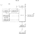
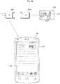
- FIG. 1 is a view showing a video display system based on the wireless transmission of content data according to an embodiment of the present invention.
- the video display system based on the wireless transmission of content data may include a content transmission device 100a, at least one content reception device 100ba, 100bb, ... (which may also be denoted by 100b), at least one display device 180a, 180b, ..., a remote controller 200, and a mobile terminal 600.
- the content transmission device 100a may have a plurality of input terminals to receive content data from a plurality of external devices.
- the content transmission device 100a can transmit content data, input from one of the external devices through a corresponding one of the input terminals, to one of the at least one content reception device 100ba, 100bb, ... in a wireless fashion.
- the external devices that are connected to the content transmission device 100a may be a camera device 101, an optical disk player 213, a game console 214, a laptop computer 215, a set-top box, etc., as shown in this figure.
- the input terminals of the content transmission device 100a may be an antenna terminal, a universal serial bus (USB) terminal, a high definition multimedia interface (HDMI) terminal, a wired local area network (LAN) terminal, an RGB terminal, an audio/video (AV) terminal, an S-video terminal, a Sony and Philips digital interconnect format (SPDIF) terminal, a secure digital (SD) terminal, a micro-SD terminal, a compact flash (CF) terminal, etc.
- USB universal serial bus
- HDMI high definition multimedia interface
- LAN local area network
- RGB RGB terminal
- AV audio/video
- S-video terminal S-video terminal
- SPDIF Sony and Philips digital interconnect format
- SD secure digital
- micro-SD terminal micro-SD terminal
- CF compact flash
- the at least one content reception device 100ba, 100bb, ... can receive predetermined content data from the content transmission device 100a in a wireless fashion, and can transmit the received content data to the at least one display device 180a, 180b, ... in a wireless fashion. Further, the at least one display device 180a, 180b, ... can display a video that corresponds to the wirelessly received content data.
- Examples of the at least one display device 180a, 180b, ... include a monitor, a TV receiver, etc. Meanwhile, a content reception device and a display device may be integrated into a single device. An example of such an integrated device may be a tablet device.
- the remote controller 200 and the mobile terminal 600 can each remotely control at least one selected from among the content transmission device 100a, the at least one content reception device 100ba, 100bb, ..., and the at least one display device 180a, 180b, ....
- the remote controller 200 can transmit a power on signal, a power off signal, a channel control signal, or a volume control signal to the content transmission device 100a, the at least one content reception device 100ba, 100bb, ..., and the at least one display device 180a, 180b, ... in a wireless fashion.
- the power on signal, the power off signal, the channel control signal, or the volume control signal may be transmitted as an infrared (IR) signal.
- the remote controller 200 can transmit a pointing signal for remote control pointing to at least one selected from among the content transmission device 100a, the at least one content reception device 100ba, 100bb, ..., and the at least one display device 180a, 180b, ....
- the pointing signal may be a radio frequency (RF) signal, rather than an IR signal.
- the mobile terminal 600 can transmit a power on signal, a power off signal, a channel control signal, or a volume control signal to the content transmission device 100a, the at least one content reception device 100ba, 100bb, ..., and the at least one display device 180a, 180b, ... in a wireless fashion.
- RF radio frequency
- the power on signal, the power off signal, the channel control signal, or the volume control signal may be transmitted as an IR signal.
- the mobile terminal 600 can transmit a pointing signal for remote control pointing to at least one selected from among the content transmission device 100a, the at least one content reception device 100ba, 100bb, ..., and the at least one display device 180a, 180b, ....
- the pointing signal may also be an RF signal, rather than an IR signal.
- the mobile terminal 600 can transmit a selection signal for selecting one of the at least one content reception device 100ba, 100bb, ... to the content transmission device 100a, and can transmit a selection signal for selecting one of the input terminals of the content transmission device 100a or selecting one of content data from the external devices to the content transmission device 100a.
- the mobile terminal 600 can transmit content data received through a first input terminal of the content transmission device 100a to a first content reception device 100ba based on the selection of the first content reception device 100ba from among the at least one content reception device 100b and the selection of the first input terminal from among the input terminals of the content transmission device 100a when a content playback setting screen including an item related to the at least one content reception device 100b, an item related to at least one of the input terminals through which the at least one content reception device 100b is connected to the content transmission device 100a, and a thumbnail image corresponding to the item related to the at least one of the input terminals, is displayed in response to an input for the execution of a content playback application. Consequently, it is possible to easily perform the transmission of content from the content transmission device 100a through the mobile terminal 600.
- the mobile terminal 600 can display a screen for wireless pairing between the content transmission device 100a and the first content reception device 100ba in response to the selection of the first content reception device 100ba from among the at least one content reception device 100b and the selection of the first input terminal from among the input terminals of the content transmission device 100a such that pairing between the content transmission device 100a and the first content reception device 100ba is performed before the transmission of content, whereby the transmission of content is easily performed.
- the mobile terminal 600 can display a first object indicating that content data are being transmitted in the first frequency band.
- the mobile terminal 600 can display a second object indicating that content data are being transmitted in the second frequency band.
- the mobile terminal 600 can display a third object indicating that content data are being transmitted in the third frequency band. Consequently, it is possible to easily recognize the frequency band in which the content transmission device 100a is transmitting content data to the first content reception device 100ba.
- the mobile terminal 600 can variably display the number of thumbnail images corresponding to the input terminals according to the item related to the at least one content reception device 100b that is selected in the content playback setting screen. Consequently, it is possible to easily recognize viewable content received through each input terminal.
- the mobile terminal 600 can receive content data and display the received content data in a portion of the screen.
- the mobile terminal 600 can transmit information set based on a setting input of at least one selected from among the image size, playback time, fast-forward, and volume of a video based on the displayed content data to the content transmission device 100a. Consequently, it is possible to improve user convenience.
- the mobile terminal 600 can perform a control operation to further transmit second content data received through the second input terminal of the content transmission device 100a to the second content reception device 100bb. Consequently, it is possible to transmit a plurality of pieces of content data.
- the mobile terminal 600 can include a display unit 680, a communication unit 610 for transmitting a control signal to the content transmission device 100a, and a controller 670 for performing control such that a content playback setting screen, including a power on item, a power off item, an input item, and a thumbnail image corresponding to the input item, is displayed in response to an input for the execution of a content playback application.
- the controller 670 can transmit content data received through the first input terminal of the content transmission device 100a to the at least one content reception device 100b based on the selection of the first input terminal as the input item. Consequently, it is possible to easily perform the transmission of content from the content transmission device 100a.
- the mobile terminal 600 can perform a control operation to power on the content transmission device 100a and the at least one content reception device 100b by transmitting power on signals to the content transmission device 100a and the at least one content reception device 100b when the power on item in the content playback setting screen is selected.
- the mobile terminal 600 can transmit a pairing signal to the content transmission device 100a after the content transmission device 100a is powered on in response to the power on signal, and may be connected to the content transmission device 100a based on a pairing response signal received from the content transmission device 100a. Consequently, it is possible to easily perform pairing.
- the content transmission device 100a may include a communication unit 135 for exchanging data with the mobile terminal 600, an interface unit 130 having a plurality of input terminals to receive content data from a plurality of external devices, and a controller 170 for performing control such that content data received through the first input terminal of the content transmission device 100a are transmitted to the first content reception device 100ba when receiving, from the mobile terminal 600, a remote control signal in response to the selection of the first content reception device 100ba from among the at least one content reception device 100b and the selection of the first input terminal from among the input terminals of the content transmission device 100a. Consequently, it is possible to easily perform the transmission of content from the content transmission device 100a.
- the content transmission device 100a can transmit a pairing signal to the first content reception device 100ba when receiving, from the mobile terminal 600, a remote control signal in response to the selection of the first content reception device 100ba from among the at least one content reception device 100b and the selection of the first input terminal from among the input terminals of the content transmission device 100a, and can perform pairing based on a pairing response signal received from the first content reception device 100ba. Consequently, it is possible to easily perform the transmission of content from the content transmission device 100a.
- the content transmission device 100a can transmit content data received through the first input terminal of the content transmission device 100a to the first content reception device 100ba in any one selected from among the first frequency band to the third frequency band depending on the state of the wireless connection between the content transmission device 100a and the first content reception device 100ba. Consequently, it is possible to transmit content data without loss or delay.
- FIG. 2A is an internal block diagram of an example of the content transmission device shown in FIG. 1 .
- the content transmission device 100a may include a broadcast reception unit 105, a memory 140, a user input interface unit 150, a sensor unit, a controller 170, and a power supply unit 190.
- the broadcast reception unit 105 may include a tuner unit 110, a demodulator 120, a communication unit 135, and an external device interface unit 130.
- the broadcast reception unit 105 may include only the tuner unit 110 and the demodulator 120. That is, the broadcast reception unit 105 may not include the communication unit 135 or the external device interface unit 130.
- the tuner unit 110 tunes to a radio frequency (RF) broadcast signal corresponding to a channel selected by a user or all pre-stored channels from among RF broadcast signals received through an antenna terminal.
- the tuner unit 110 converts the tuned RF broadcast signal into an intermediate frequency (IF) signal or a baseband video or audio signal.
- RF radio frequency
- the tuner unit 110 converts the selected RF broadcast signal into a digital IF (DIF) signal.
- the tuner unit 110 converts the selected RF broadcast signal into an analog baseband video or audio signal (CVBS/SIF). That is, the tuner unit 110 can process the digital broadcast signal or the analog broadcast signal.
- the analog baseband video or audio signal (CVBS/SIF) output from the tuner unit 110 may be directly input to the controller 170.
- the tuner unit 110 may sequentially tune to RF broadcast signals of all broadcast channels stored using a channel memory function, among RF broadcast signals received through the antenna, and may convert the tuned RF broadcast signals into intermediate frequency signals or baseband video or audio signals.
- the tuner unit 110 may include a plurality of tuners in order to receive broadcast signals of a plurality of channels.
- the tuner unit 110 may include a single tuner that is capable of simultaneously receiving broadcast signals of a plurality of channels.
- the demodulator 120 can receive the digital IF (DIF) signal converted by the tuner unit 110, and can perform demodulation. After performing demodulation and channel decoding, the demodulator 120 may output a stream signal (TS).
- the stream signal may be a multiplexed video signal, a multiplexed audio signal, or a multiplexed data signal.
- the stream signal output from the demodulator 120 may be input to the controller 170.
- the controller 170 can perform demultiplexing, video/audio signal processing, etc. Subsequently, the controller 170 can transmit the processed signal to the at least one content reception device 100ba, 100bb, ... in a wireless fashion.
- the external device interface unit 130 may include an antenna terminal, a USB terminal, an HDMI terminal, a wired LAN terminal, an RGB terminal, an AV terminal, an S-video terminal, an SPDIF terminal, an SD terminal, a micro-SD terminal, and a CF terminal.
- the external device interface unit 130 can transmit or receive data to or from an external device, such as a set-top box, connected through one of the input terminals.
- the external device interface unit 130 may include an A/V input and output unit.
- the external device interface unit 130 may be connected to an external device, such as a digital versatile disk (DVD) player, a Blu-ray player, a game console, a camera, a camcorder, a computer (a laptop computer), or a set-top box, in a wired or wireless fashion.
- an external device such as a digital versatile disk (DVD) player, a Blu-ray player, a game console, a camera, a camcorder, a computer (a laptop computer), or a set-top box, in a wired or wireless fashion.
- DVD digital versatile disk
- Blu-ray player Blu-ray player
- game console a digital camera
- camcorder a computer
- computer a laptop computer
- set-top box a set-top box
- the communication unit 135 may provide an interface for connecting the content transmission device 100a to a wired or wireless network, including the Internet.
- the communication unit 135 can receive content or data provided by a content provider or a network operator over a network, such as the Internet.
- the communication unit 135 may include a wired communication unit 135a and a wireless communication unit 135b.
- the communication unit 135 may also exchange data with the mobile terminal 600 or the remote controller 200 through the wireless communication unit 135b.
- the memory 140 may store a program for processing and controlling signals in the controller 170.
- the first storage unit 140 may store a processed video, audio, or data signal.
- the memory 140 may temporarily store a video, audio, or data signal input to the external device interface unit 130.
- the memory 140 may store information about a specific broadcast channel using a channel memory function, such as a channel map.
- the memory 140 is provided separately from the controller 170.
- the present invention is not limited thereto.
- the memory 140 may be included in the controller 170.
- the user input interface unit 150 may transfer a signal input by a user to the controller 170, or may transfer a signal from the controller 170 to the user.
- the user input interface unit 150 can transmit/receive a user input signal, such as power on/off, channel selection, or screen setting, to/from the remote controller 200 or the mobile terminal 600, can transfer a user input signal input from a local key, such as a power key, a channel key, a volume key, or a setting key, to the controller 170, can transfer a user input signal input from a sensor unit for sensing a gesture of a user to the controller 170, or can transmit a signal from the controller 170 to the sensor unit.
- a user input signal such as power on/off, channel selection, or screen setting
- a local key such as a power key, a channel key, a volume key, or a setting key
- the controller 170 can demultiplex streams input through the tuner unit 110, the demodulator 120, the communication unit 135, or the external device interface unit 130, or can process the demultiplexed signals to generate and output a video or audio output signal.
- the video signal processed by the controller 170 may be transmitted to the at least one content reception device 100ba, 100bb, ... in a wireless fashion.
- the audio signal processed by the controller 170 may be transmitted to the at least one content reception device 100ba, 100bb, ... in a wireless fashion. Further, the controller 170 may include a demultiplexer and a video processing unit, which will hereinafter be described with reference to FIG. 3 .
- the controller 170 can control the operations of the respective units in the content transmission device 100a.
- the power supply unit 190 may supply power to the content transmission device 100a.
- the power supply unit 190 may supply power to the controller 170, which may be embodied in the form of a system on chip (SOC).
- the power supply unit 190 may include an AC/DC converter for converting AC power into DC power and a DC/DC converter for changing the level of the DC power.
- the remote controller 200 can transmit a user input to the user input interface unit 150.
- the remote controller 200 may use Bluetooth communication, radio frequency (RF) communication, infrared (IR) communication, ultra wideband (UWB) communication, or ZigBee communication.
- the remote controller 200 can receive a video, audio, or data signal output from the user input interface unit 150 such that the remote controller 200 displays the received signal or outputs the received signal in the form of audible sound.
- the content transmission device 100a may be a fixed or mobile digital broadcast receiver that is capable of receiving a digital broadcast.
- the block diagram of the content transmission device 100a shown in FIG. 2A is a view illustrating an embodiment of the present invention.
- the respective components of the block diagram may be combined, added, or omitted depending on the specifications of the content transmission device 100a that is actually embodied. That is, two or more components may be combined into a single component or one component may be divided into two or more components as needed.
- the function performed by each block is intended for description of the embodiment of the invention, and its detailed action or device does not limit the scope of the invention.
- FIG. 2B is an internal block diagram of an example of a content reception device shown in FIG. 1 .
- the content reception device 100b may include a communication unit 136, an external device interface unit 131, a memory 141, a user input interface unit 151, a controller 171, and a power supply unit 191.
- the operation of the external device interface unit 131, the memory 141, the user input interface unit 151, the controller 171, and the power supply unit 191 may be similar to the operation of the external device interface unit 130, the memory 140, the user input interface unit 150, the controller 170, and the power supply unit 190 of the content transmission device 100a shown in FIG. 2A .
- the communication unit 136 can receive content data from the content transmission device 100a in a wireless fashion, and may directly transmit the received content data to a display device 180 in a wireless fashion without additional signal processing. Alternatively, the communication unit 136 can receive content data from the content transmission device 100a in a wireless fashion, and can transmit the content data to a display device 180 in a wireless fashion after the content data is processed by the controller 171.
- the communication unit 136 may include a first communication unit 136a and a second communication unit 136b.
- the first communication unit 136a can receive content data from the content transmission device 100a, and the second communication unit 136b can transmit the content data to the display device 180 in a wireless fashion.
- the display device 180 may include a display module 181, a controller 183, an audio output unit 185, and a communication unit.
- the communication unit can receive content data from the content reception device 100b in a wireless fashion.
- the controller 183 can process the received content data.
- the video signal processed by the controller 171 may be input to the display module 181 such that a video based on the video signal is displayed on the display module 181.
- the controller 183 can process the received content data.
- the audio signal processed by the controller 171 may be output through the audio output unit 185 in the form of audible sound.
- FIG. 3 is an internal block diagram of an example of the controller shown in FIG. 2A .
- the controller 170 may include a demultiplexer 310, a video processing unit 320, a processor 330, an on-screen display (OSD) generator 340, a mixer 345, a frame rate converter (FRC) 350, and a formatter 360.
- the controller 170 may further include an audio processing unit and a data processing unit.
- the demultiplexer 310 can demultiplex an input stream. For example, when an MPEG-2 TS is input, the demultiplexer 310 can demultiplex the MPEG-2 TS into video, audio, and data signals.
- the stream signal that is input to the demultiplexer 310 may be a stream signal output from the tuner unit 110, the demodulator 120, or the external device interface unit 130.
- the video processing unit 320 can process a demultiplexed video signal.
- the video processing unit 320 may include a video decoder 325 and a scaler 335.
- the video decoder 325 can decode the demultiplexed video signal
- the scaler 335 can scale the resolution of the decoded video signal such that the video signal can be output to the at least one display device 180a, 180b, ....
- Decoders based on various standards may be used as the video decoder 325.
- an MPEG-2 decoder, an H264 decoder, a 3D image decoder, such as a color image decoder or a depth image decoder, or a multi-viewpoint image decoder may be used as the video decoder 325.
- the processor 330 controls the overall operation of the content transmission device 100a or the controller 170.
- the processor 330 can control the tuner unit 110 to tune to an RF broadcast corresponding to a channel selected by a user or a pre-stored channel.
- the processor 330 can control the content transmission device 100a based on a user command input through the user input interface unit 150 or an internal program.
- the processor 330 can control data transmission to the communication unit 135 or the external device interface unit 130.
- the processor 330 can control the operation of the demultiplexer 310, the video processing unit 320, and the OSD generator 340 of the first processor 170.
- the OSD generator 340 can generate an OSD signal, either in response to a user input or autonomously.
- the OSD generator 340 can generate a signal for displaying various kinds of information on the screen of the at least one display device 180a, 180b, ... in the form of graphics or text based on a user input signal.
- the generated OSD signal may include various data from the content transmission device 100a, such as user interface screens, various menu screens, widgets, and icons.
- the generated OSD signal may include a 2D object or a 3D object.
- the OSD generator 340 can generate a pointer that can be displayed on the display unit based on a pointing signal input from the remote controller 200.
- the pointer may be generated by a pointing signal processing unit.
- the OSD generator 340 may include such a pointing signal processing unit.
- the pointing signal processing unit may not be provided in the OSD generator 340 but may be provided separately.
- the mixer 345 can mix the OSD signal, generated by the OSD generator 340, with the decoded video signal processed by the video processing unit 320.
- the mixed video signal may be provided to the frame rate converter 350.
- the frame rate converter 350 can convert the frame rate of an input video. Alternatively, the frame rate converter 350 may directly output an input video without converting the frame rate of the input video.
- the formatter 360 can arrange left-eye video frames and right-eye video frames of a 3D video, the frame rate of which has been converted.
- the formatter 360 can output a synchronizing signal Vsync for opening a left-eye glass and a right-eye glass of a 3D viewing device.
- the formatter 360 can change the format of the input video signal into the format of a video signal that is to be displayed on the display device, and may output the changed video signal.
- the formatter 360 can change the format of a 3D video signal.
- the formatter 360 may change the format of the 3D video signal into any one selected from among various 3D formats, such as a side-by-side format, an up-and-down format, a sequential frame format, an interlaced format, and a checker box format.
- the formatter 360 can convert a 2D video signal into a 3D video signal.
- the formatter 360 can detect an edge or a selectable object in a 2D video signal, and separate an object based on the detected edge or the selectable object from the 2D video signal to generate a 3D video signal according to a 3D video generation algorithm.
- the generated 3D video signal may be divided into a left-eye video signal L and a right-eye video signal R, which may be arranged appropriately.
- a 3D processor for processing 3D effects may be further provided after the formatter 360.
- the 3D processor can control the brightness, tint, and color of a video signal in order to improve the 3D effects.
- the 3D processor can perform signal processing in order to sharpen nearby items and to blur distant items.
- the function of the 3D processor may be incorporated into the formatter 360 or the video processing unit 320.
- the audio processing unit in the controller 170 can process a demultiplexed audio signal.
- the audio processing unit may include various decoders.
- the audio processing unit in the controller 170 can control the bass, treble, and volume of an audio signal.
- the data processing unit in the controller 170 can process a demultiplexed data signal.
- the demultiplexed data signal is an encoded data signal
- the data processing unit can decode the demultiplexed data signal.
- the encoded data signal may be electronic program guide (EPG) information containing broadcast information, such as a start time and an end time, of a broadcast program provided by each channel.
- EPG electronic program guide
- the block diagram of the controller 170 shown in FIG. 3 is a view illustrating an embodiment of the present invention.
- the respective components of the block diagram may be combined, added, or omitted depending on the specifications of the controller 170 that is actually embodied.
- the frame rate converter 350 and the formatter 360 may not be provided in the controller 170 but may be separately provided.
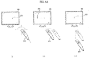
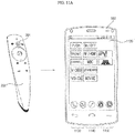
- FIG. 4A is a view showing a control method of the remote controller shown in FIG. 2A .
- a pointer 205 corresponding to the remote controller 200 is displayed on the display device 180.
- a user can move or rotate the remote controller 200 up and down, side to side ( FIG. 4A(b) ), or back and forth ( FIG. 4A(c) ).
- the pointer 205 displayed on the display device 180 corresponds to the motion of the remote controller 200. Since the pointer 205 corresponding to the remote controller 200 is moved and displayed in response to the motion of the remote controller 200 in a 3D space, as shown in these figures, the remote controller 200 can be named a spatial remote controller or a 3D pointing device.
- FIG. 4A(b) illustrates that, when the user moves the remote controller 200 to the left, the pointer 205 moves to the left on the display device 180 in response to the motion of the remote controller 200.
- Information about the motion of the remote controller 200 sensed by a sensor of the remote controller 200, is transmitted to the content transmission device.
- the content transmission device may calculate the coordinates of the pointer 205 from information about the motion of the remote controller 200.
- the content transmission device may display the pointer 205 such that the pointer 205 corresponds to the calculated coordinates.
- FIG. 4A(c) illustrates when the user moves the remote controller 200 away from the display device 180 while pressing a specific button on the remote controller 200.
- the selected area in the display device 180 corresponding to the pointer 205 can be zoomed in, and thus enlarged, on the display device 180.
- the selected area in the display device 180 corresponding to the pointer 205 can be zoomed out, and thus contracted, on the display device 180.
- the selected area may be zoomed out when the remote controller 200 moves away from the display device 180, and the selected area may be zoomed in when the remote controller 200 moves toward the display device 180.
- the upward, downward, leftward, and rightward movement of the remote controller 200 may not be recognized in the state in which a specific button of the remote controller 200 is pressed. That is, when the remote controller 200 moves away from or toward the display device 180, the upward, downward, leftward, and rightward movement of the remote controller 200 may not be recognized, but only the forward and rearward movement of the remote controller 200 may be recognized. In the state in which a specific button of the remote controller 200 is not pressed, only the pointer 205 moves in response to the upward, downward, leftward, and rightward movement of the remote controller 200.
- the movement speed or direction of the pointer 205 may correspond to the movement speed or direction of the remote controller 200.
- FIG. 4B is an internal block diagram of the remote controller shown in FIG. 2A .
- the remote controller 200 may include a wireless communication unit 420, a user input unit 430, a sensor unit 440, an output unit 450, a power supply unit 460, a memory 470, and a controller 480.
- the wireless communication unit 420 can transmit and receive signals to and from any one of the content transmission devices according to the embodiments of the present invention described above.
- the content transmission device 100a which is one of the content transmission devices according to the embodiments of the present invention, will be described by way of example.
- the wireless communication unit 420 may include an RF module 421 for transmitting and receiving signals to and from the content transmission device 100a in accordance with an RF communication standard.
- the wireless communication unit 420 may further include an IR module 423 for transmitting and receiving signals to and from the content transmission device 100a in accordance with an IR communication standard.
- the remote controller 200 can transmit a signal containing information about the motion of the remote controller 200 to the content transmission device 100a through the RF module 421.
- the remote controller 200 can receive a signal from the content transmission device 100a through the RF module 421.
- the remote controller 200 can transmit a command, such as a power on/off command, a channel change command, or a volume change command, to the content transmission device 100a through the IR module 423.
- the user input unit 430 may include a keypad, a button, a touchpad, or a touchscreen.
- the user can input a command related to the content transmission device 100a to the remote controller 200 by manipulating the user input unit 430.
- the user input unit 430 includes a hard key button
- the user can input a command related to the content transmission device 100a to the remote controller 200 by pushing the hard key button.
- the user input unit 430 includes a touchscreen
- the user can input a command related to the content transmission device 100a to the remote controller 200 by touching a soft key on the touchscreen.
- the user input unit 430 may include various kinds of input tools, such as a scroll key and a jog wheel, which do not limit the scope of the present invention.
- the sensor unit 440 may include a gyro sensor 441 or an acceleration sensor 443.
- the gyro sensor 441 can sense information about the motion of the remote controller 200.
- the gyro sensor 441 may sense information about the motion of the remote controller 200 in x, y, and z-axis directions.
- the acceleration sensor 443 may sense information about the speed of movement of the remote controller 200.
- the sensor unit 440 may further include a distance sensor for sensing the distance between the remote controller 200 and the display device 180.
- the output unit 450 may output a video or audio signal corresponding to the manipulation of the user input unit 430 or to a signal received from the content transmission device 100a.
- the user can recognize whether the user input unit 430 has been manipulated or whether the content transmission device 100a has been controlled, through the output unit 450.
- the output unit 450 may include a light emitting diode (LED) module 451 configured to be turned on when the user input unit 430 is manipulated or when a signal is received from or transmitted to the content transmission device 100a through the wireless communication module 420, a vibration module 453 for generating vibration, a sound output module 455 for outputting sound, or a display module 457 for outputting a video.
- LED light emitting diode
- the power supply unit 460 may supply power to the remote controller 200.
- the power supply unit 460 may interrupt the supply of power to the remote controller 200 in order to reduce power consumption.
- the power supply unit 460 may resume the supply of power to the remote controller 200 when a predetermined key of the remote controller 200 is manipulated.
- the memory 470 may store various kinds of programs and application data necessary to control or drive the remote controller 200.
- the remote controller 200 may wirelessly transmit and receive signals to and from the content transmission device 100a in a predetermined frequency band through the RF module 421.
- the controller 480 of the remote controller 200 may store, in the memory 470, information about the frequency band within which signals are transmitted to and received from the content transmission device 100a, which is paired with the remote controller 200 in a wireless fashion, and may refer to the stored information.
- the controller 480 can control the overall operation of the remote controller 200.
- the controller 480 can transmit a signal corresponding to the manipulation of a predetermined key of the user input unit 430 or a signal corresponding to the motion of the remote controller 200 sensed by the sensor unit 440 to the content transmission device 100a through the wireless communication unit 420.
- the user input interface unit 150 of the content transmission device 100a may include a wireless communication unit 411 for wirelessly transmitting and receiving signals to and from the remote controller 200 and a coordinate value calculator 415 for calculating a coordinate value of a pointer corresponding to the motion of the remote controller 200.
- the user input interface unit 150 can wirelessly transmit and receive signals to and from the remote controller 200 through an RF module 412. In addition, the user input interface unit 150 can receive a signal transmitted by the remote controller 200 in accordance with an IR communication standard through an IR module 413.
- the coordinate value calculator 415 can correct a hand tremor or an error in a signal corresponding to the motion of the remote controller 200, received through the wireless communication unit 411, in order to calculate coordinate values (x, y) of the pointer 205 that is to be displayed on the display device 180.
- the controller 170 may differentiate information about the motion and key manipulation of the remote controller 200 from the signal received from the remote controller 200, and can control the content transmission device 100a in response thereto.
- the remote controller 200 may calculate coordinate values of the pointer corresponding to the motion thereof, and may output the calculated coordinate values to the user input interface unit 150 of the content transmission device 100a.
- the user input interface unit 150 of the content transmission device 100a can transmit information about the received coordinate values of the pointer to the controller 170 without correcting a hand tremor or an error.
- the coordinate value calculator 415 may be provided in the controller 170, rather than in the user input interface unit 150, unlike what is shown in this figure.
- FIG. 5 is an internal block diagram of the mobile terminal shown in FIG. 1 .
- the terminal 600 may include a wireless communication unit 610, an audio/video (A/V) input unit 620, a user input unit 630, a sensing unit 640, an output unit 650, a memory 660, an interface unit 625, a controller 670, and a power supply unit 690.
- the wireless communication unit 610 may include a broadcast reception module 611, a mobile communication module 613, a wireless Internet module 615, a sound communication unit 617, and a global positioning system (GPS) module 619.
- GPS global positioning system
- the broadcast reception module 611 can receive a broadcast signal and/or broadcast-related information from an external broadcast management server through a broadcast channel.
- the broadcast channel may include a satellite channel and a terrestrial channel.
- the broadcast signal and/or the broadcast-related information received through the broadcast reception module 611 may be stored in the memory 660.
- the mobile communication module 613 can transmit and receive a wireless signal to and from at least one selected from among a base station, an external terminal, and a server over a mobile communication network.
- the wireless signal may include a voice call signal, a video communication call signal, or various types of data based on text/multimedia message transmission and reception.
- the wireless Internet module 615 is a module for wireless Internet access.
- the wireless Internet module 615 may be mounted inside or outside the mobile terminal 600.
- the wireless Internet module 615 can perform wireless communication based on Wi-Fi or wireless communication based on Wi-Fi Direct.
- the sound communication unit 617 can perform sound communication.
- the sound communication unit 617 may add predetermined information data to audio data that are to be output in order to output sound.
- the sound communication unit 617 may extract predetermined information from an external sound in the sound communication mode.
- Bluetooth, radio frequency identification (RFID), infrared data association (IrDA), ultra wideband (UWB), or ZigBee may be used as short-range communication technology.
- the GPS module 619 can receive position information from a plurality of artificial GPS satellites.
- the A/V input unit 620 may be provided for inputting an audio signal or video signal.
- the A/V input unit 620 may include a camera 621 and a microphone 623.
- the user input unit 630 can generate key input data that are input by the user to control the operation of the terminal.
- the user input unit 630 may include a keypad, a dome switch, and a touchpad (static pressure or electrostatic).
- a touchpad static pressure or electrostatic
- the touchpad forms a layered structure together with a display unit 680
- an assembly consisting of the touchpad and the display unit 680 may be called a touchscreen.
- the sensing unit 640 can sense the current state of the mobile terminal 600, such as the activated or deactivated state of the mobile terminal 600, the position of the mobile terminal 600, and whether user contact with the mobile terminal 600 has occurred, to generate a sensing signal for controlling the operation of the mobile terminal 600.
- the sensing unit 640 may include a proximity sensor 641, a pressure sensor 643, and a motion sensor 645.
- the motion sensor 645 may sense the motion or position of the mobile terminal 600 using an acceleration sensor, a gyro sensor, a gravity sensor, or the like.
- the gyro sensor is a sensor for measuring the angular velocity of the mobile terminal 600.
- the gyro sensor may sense the angle at which the mobile terminal 600 is rotated relative to a reference direction.
- the output unit 650 may include a display unit 680, an audio output unit 653, an alarm unit 655, and a haptic module 657.
- the display unit 680 may output information that is processed by the mobile terminal 600.
- the display unit 680 may display information that is processed by the mobile terminal 600.
- the display unit 680 and the touchpad are disposed as a layered structure to form a touchscreen as described above, the display unit 680 may also be used as an input device that allows a user to input information via touch, in addition to an output device.
- the audio output unit 653 may output audio data, which are received from the wireless communication unit 610 or are stored in the memory 660.
- the audio output unit 653 may include a speaker and a buzzer.
- the alarm unit 655 can output a signal indicating the occurrence of an event of the mobile terminal 600.
- the alarm unit 655 can output a signal in the form of vibrations.
- the haptic module 657 may generate a variety of tactile effects that the user can feel. A typical example of the tactile effects generated by the haptic module 657 may be a vibration effect.
- the memory 660 can store a program for processing or control of the controller 670, or may temporarily store input or output data (e.g. phonebooks, messages, still pictures, and motion pictures).
- the interface unit 625 can provide an interface between the mobile terminal 600 and all external devices connected to the mobile terminal 600.
- the interface unit 625 can receive data or power from the external devices, and transfer the received data or power to the respective components of the mobile terminal 600.
- data may be transmitted from the mobile terminal 600 to the external devices via the interface unit 625.
- the controller 670 can control the operation of the respective components of the mobile terminal 600, thereby controlling the overall operation of the mobile terminal 600.
- the controller 670 can perform control or processing for voice communication, data communication, and video communication.
- the controller 670 may further include a multimedia playback module 681 for playing back multimedia content.
- the multimedia playback module 681 may be incorporated into the controller 670 in the form of hardware.
- the multimedia playback module 681 may be configured separately from the controller 670 in the form of software.
- the power supply unit 690 can supply external power or internal power to the respective components of the mobile terminal 600 under the control of the controller 670.
- the block diagram of the mobile terminal 600 shown in FIG. 5 is a view illustrating an embodiment of the present invention. Respective components of the block diagram may be combined, added, or omitted depending on the specifications of the mobile terminal 600 that is actually embodied. That is, two or more components may be combined into a single component or one component may be divided into two or more components as needed.
- the function performed by each block is given for description of the embodiment of the invention, and detailed actions or device pertaining thereto do not limit the scope of the invention.
- FIG. 6 is a flowchart showing an example of a method of operating a mobile terminal according to an embodiment of the present invention
- FIGS. 7 to 12G are reference views illustrating the operation method of FIG. 6 .
- the controller 670 of the mobile terminal 600 executes a content playback application in response to an input for the execution of the content playback application (S610).
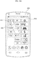
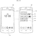
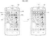
- the controller 670 of the mobile terminal 600 can execute the content playback application, and can display a content playback setting screen 820, as shown in FIG. 8B .
- the controller 670 of the mobile terminal 600 can transmit a pairing signal to the content transmission device 100a through the communication unit 610.
- the controller 670 of the mobile terminal 600 can receive a pairing response signal from the content transmission device 100a through the communication unit 610. Consequently, the controller 670 of the mobile terminal 600 can perform a control operation to achieve pairing between the mobile terminal 600 and the content transmission device 100a.
- the pairing signal, the pairing response signal, and the signals that are transmitted and received between the mobile terminal 600 and the content transmission device 100a after pairing may be RF signals.
- the controller 670 of the mobile terminal 600 can display a content playback setting screen 820, including an item related to the at least one content reception device, an item related to at least one of the input terminals through which the at least one content reception device is connected to the content transmission device 100a, and a thumbnail image corresponding to the item related to the at least one of the input terminals, in response to the input for the execution of the content playback application.
- the content playback setting screen 820 may include items related to a plurality of content reception devices, such as TV1, TV2, STB (a set-top box), BD (a Blu-ray player), and Pad (a tablet device). As shown in FIG. 8B , the content playback setting screen 820 may also include items related to a plurality of input terminals, such as RF (corresponding to an antenna terminal), HDMI, USB, LAN (a wired communication terminal), Wi-Fi (a wireless communication terminal), Composite, and AV, which are provided in the content transmission device 100a.
- RF corresponding to an antenna terminal
- HDMI HDMI
- USB LAN
- Wi-Fi a wireless communication terminal
- Composite AV
- the content playback setting screen 820 may include thumbnail images corresponding to RF, HDMI, USB, LAN, Wi-Fi, Composite, and AV. That is, the content playback setting screen 820 may include thumbnail images of content data that are input through the terminals, such as RF, HDMI, USB, LAN, Wi-Fi, Composite, and AV.
- the controller 670 of the mobile terminal 600 can select a content reception device and an input terminal in response to an input for selecting the content reception device and an input for selecting the input terminal (S620). Subsequently, the controller 670 of the mobile terminal 600 can transmit content data received through the selected input terminal to the selected content reception device (S630).
- the controller 670 of the mobile terminal 600 can select an item related to a first content reception device from among the items related to the content reception devices in the content playback setting screen 820, and select an item related to a first input terminal from among the items related to the input terminals in the content playback setting screen 820, in response to a user's touch input.
- the controller 670 of the mobile terminal 600 can transmit the selected information to the content transmission device 100a.
- the content transmission device 100a can wirelessly transmit content data, received through the first input terminal, to the first content reception device based on the information about the selection of the first content reception device and the information about the selection of the first input terminal, received from the mobile terminal 600.
- the content transmission device 100a may use a specific frequency band, which is set based on the operation shown in FIG. 7 .
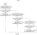
- FIG. 7 is a flowchart showing a method of operating the content transmission device 100a.
- the controller 170 of the content transmission device 100a can transmit a pairing signal to the first content reception device 100ba through the communication unit 135, and can receive a pairing response signal from the first content reception device 100ba through the communication unit 135.
- the controller 170 of the content transmission device 100a can perform pairing between the content transmission device 100a and the first content reception device 100ba. After pairing has been completed, the controller 170 of the content transmission device 100a can check a first frequency band for the transmission of content data (S710).
- the first frequency band may be a frequency band of 2.4 GHz for Wi-Fi communication.
- the controller 170 of the content transmission device 100a can transmit a reference signal of the first frequency band to the first content reception device 100ba, and can receive a response signal from the first content reception device 100ba.
- the controller 170 of the content transmission device 100a can compare the response signal with the reference signal in order to check a data transfer rate, the state of the frequency band, etc.
- the controller 170 of the content transmission device 100a can determine whether the first frequency band is usable by checking the frequency band (S715). Upon determining that the first frequency band is usable, the controller 170 of the content transmission device 100a can transmit content data to the first content reception device 100ba in the first frequency band (S720).
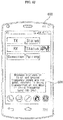
- the controller 170 of the content transmission device 100a can transmit information about the transmission in the first frequency band to the mobile terminal 600. Consequently, when the transmission is being performed in the first frequency band, as shown in FIG. 8H , the controller 670 of the mobile terminal 600 can display a first object 888 indicating that the transmission is being performed in the first frequency band.
- step S725 is performed. That is, the controller 170 of the content transmission device 100a can check a second frequency band for the transmission of content data (S725).
- the second frequency band may be a frequency band of 5 GHz for Wi-Fi communication.
- the controller 170 of the content transmission device 100a can transmit a reference signal of the second frequency band to the first content reception device 100ba, and can receive a response signal from the first content reception device 100ba.
- the controller 170 of the content transmission device 100a can compare the response signal with the reference signal in order to check a data transfer rate, the state of the frequency band, etc.
- the controller 170 of the content transmission device 100a can determine whether the second frequency band is usable by checking the frequency band (S728). Upon determining that the second frequency band is usable, the controller 170 of the content transmission device 100a can transmit content data to the first content reception device 100ba in the second frequency band (S730).
- the controller 170 of the content transmission device 100a can transmit information about the transmission in the second frequency band to the mobile terminal 600. Consequently, when the transmission is being performed in the second frequency band, as shown in FIG. 8I , the controller 670 of the mobile terminal 600 can display a second object 889 indicating that the transmission is being performed in the second frequency band.
- step S735 is performed. That is, the controller 170 of the content transmission device 100a can check a third frequency band for the transmission of content data (S735).
- the third frequency band may be a frequency band of 50 GHz for WiGig or WiHD communication.
- the controller 170 of the content transmission device 100a can transmit a reference signal of the third frequency band to the first content reception device 100ba, and can receive a response signal from the first content reception device 100ba.
- the controller 170 of the content transmission device 100a can compare the response signal with the reference signal in order to check a data transfer rate, the state of the frequency band, etc.
- the controller 170 of the content transmission device 100a can determine whether the third frequency band is usable by checking the frequency band (S738). Upon determining that the third frequency band is usable, the controller 170 of the content transmission device 100a can transmit content data to the first content reception device 100ba in the third frequency band (S740). When the content data are stably transmitted to the first content reception device 100ba in the third frequency band, the controller 170 of the content transmission device 100a can transmit information about the transmission in the third frequency band to the mobile terminal 600.
- the controller 670 of the mobile terminal 600 can display a third object 891 indicating that the transmission is being performed in the third frequency band.
- content data may be stably transmitted from the content transmission device 100a to the first content reception device 100ba. Also, since three frequency bands are used, the video display system based on the wireless transmission of content data shown in FIG. 1 may be named a three-band system.
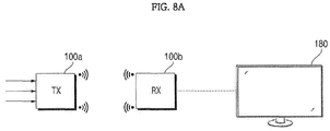
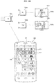
- FIG. 8A shows a video display system 10 based on the wireless transmission of content data as shown in FIG. 1 .
- the mobile terminal 600 can select an input terminal of the content transmission device 100a and a content reception device.
- the mobile terminal 600 can select one of the content reception devices 100ba, 100bb, ..., and select one of the input terminals provided in the content transmission device 100a.
- the controller 670 of the mobile terminal 600 can execute the content playback application, and can display a content playback setting screen 820, as shown in FIG. 8B .
- the content playback setting screen 820 may include items related to a plurality of content reception devices, such as TV1, TV2, STB (a set-top box), BD (a Blu-ray player), and Pad (a tablet device). As shown in FIG. 8B , the content playback setting screen 820 may also include items related to a plurality of input terminals, such as RF (corresponding to an antenna terminal), HDMI, USB, LAN (a wired communication terminal), Wi-Fi (a wireless communication terminal), Composite, and AV, which are provided in the content transmission device 100a. As shown in FIG. 8B , the content playback setting screen 820 may include thumbnail images corresponding to RF, HDMI, USB, LAN, Wi-Fi, Composite, and AV. That is, the content playback setting screen 820 may include thumbnail images of content data that are input through the terminals, such as RF, HDMI, USB, LAN, Wi-Fi, Composite, and AV.
- RF corresponding to an antenna terminal
- HDMI HDMI
- USB LAN
- Wi-Fi a wireless
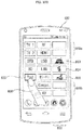
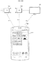
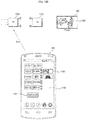
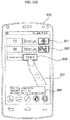
- FIG. 8C shows when a TV1 item 831 in the content playback setting screen 820 is selected by a finger 800 of the user. That is, FIG. 8C shows when a first content reception device 100ba is selected from a plurality of content reception devices.
- FIG. 8D shows when an HDMI item in the content playback setting screen 820 is selected by the finger 800 of the user. That is, FIG. 8D shows when an HDMI terminal is selected as an input terminal.
- the controller 670 of the mobile terminal 600 can display a thumbnail image 852 corresponding to content data input through the HDMI terminal in a highlighted state, as shown in FIG. 8D , in response to the selection of the HDMI item.
- FIG. 8E shows when the thumbnail image 852 corresponding to the HDMI item in the content playback setting screen 820 is selected by the finger 800 of the user.
- the controller 670 of the mobile terminal 600 can transmit information about the selection of the first content reception device 100ba corresponding to the TV1 item 831 and information about the selection of the HDMI terminal of the content transmission device 100a to the content transmission device 100a.
- the controller 170 of the content transmission device 100a can transmit content data input through the HDMI terminal of the content transmission device 100a to the first content reception device 100ba, which corresponds to the TV1 item 831 based on the information received from the mobile terminal 600.
- the controller 670 of the mobile terminal 600 can display a screen 860 for wireless pairing, as shown in FIG. 8F .
- the controller 670 of the mobile terminal 600 can display a screen 860 for wireless pairing between the content transmission device 100a and the first content reception device 100ba in response to the selection of the first content reception device 100ba from among the at least one content reception device 100b and the selection of the first input terminal from among the input terminals.
- the screen 860 for wireless pairing may include an item related to the status of the transmission device, an item related to the status of the reception device, a thumbnail image 892 corresponding to content data to be transmitted, and a pairing item 883.
- FIG. 8F shows when the pairing item 883 in the screen 860 for wireless pairing is selected by the finger 800 of the user. Consequently, the controller 670 of the mobile terminal 600 can transmit a control signal for performing pairing between the content transmission device 100a and the first content reception device 100ba to the content transmission device 100a.
- the controller 170 of the content transmission device 100a can receive the control signal from the mobile terminal, and can perform pairing between the content transmission device 100a and the first content reception device 100ba based on the received control signal.
- the controller 170 of the content transmission device 100a can transmit a pairing signal to the first content reception device 100ba, and can perform pairing based on a pairing response signal received from the first content reception device 100ba.
- the controller 170 of the content transmission device 100a can transmit a pairing completion signal to the mobile terminal 600 after pairing has been completed.
- the controller 670 of the mobile terminal 600 can display a transmission start object 886 for the transmission of content data, as shown in FIG. 8G .
- the controller 670 of the mobile terminal 600 can perform a control operation to switch the pairing item shown in FIG. 8F to a start item 884 and then to display the start item 884.
- the controller 670 of the mobile terminal 600 can transmit a data transmission start signal to the content transmission device 100a.
- the controller 170 of the content transmission device 100a can transmit content data input through the HDMI terminal of the content transmission device 100a to the first content reception device 100ba based on the data transmission start signal from the mobile terminal 600. As a result, content data desired by the user can be transmitted, thereby improving user convenience.
- the controller 170 of the content transmission device 100a can transmit information about the transmission in the first frequency band to the mobile terminal 600. Consequently, when the transmission is being performed in the first frequency band, as shown in FIG. 8H , the controller 670 of the mobile terminal 600 can display a first object 888 indicating that the transmission is being performed in the first frequency band.
- the controller 170 of the content transmission device 100a can transmit information about the transmission in the second frequency band to the mobile terminal 600. Consequently, when the transmission is being performed in the second frequency band, as shown in FIG. 8I , the controller 670 of the mobile terminal 600 can display a second object 889, indicating that the transmission is being performed in the second frequency band.
- the controller 170 of the content transmission device 100a can transmit information about the transmission in the third frequency band to the mobile terminal 600. Consequently, when the transmission is being performed in the third frequency band, as shown in FIG. 8J , the controller 670 of the mobile terminal 600 can display a third object 891, indicating that the transmission is being performed in the third frequency band. As a result, the user can easily recognize the frequency band in which the transmission is being performed.
- the controller 170 of the content transmission device 100a can transmit information about the content data that are being transmitted to the mobile terminal 600.
- the controller 670 of the mobile terminal 600 can receive the content data, and can display the received content data in a portion of the screen.
- the controller 670 of the mobile terminal 600 can display a thumbnail image 1161 corresponding to the content data that are being transmitted on another screen, e.g. an Internet screen 1162, in an overlaying fashion.
- the controller 670 of the mobile terminal 600 can transmit information set based on a setting input of at least one selected from among the image size, playback time, fast-forward, and volume of a video based on the displayed content data to the content transmission device 100a.
- FIG. 8L shows when the thumbnail image 1161 is selected by the finger 800 of the user.
- the controller 670 of the mobile terminal 600 can display a playback time setting object 1163 in addition to the display of an enlarged thumbnail image 1161a, as shown in FIG. 8I .
- the controller 670 of the mobile terminal 600 can transmit information about the previous time P2 to the content transmission device 100a.
- the controller 170 of the content transmission device 100a can perform a control operation to content data from the changed playback time are transmitted to the first content reception device 100ba based on information about the changed playback time from the mobile terminal 600. Consequently, the user can directly view the content data from a desired time.
- the controller 170 of the content transmission device 100a can transmit corresponding content data to the mobile terminal 600.
- the controller 670 of the mobile terminal 600 can display a thumbnail image corresponding to the content data, the playback time of which has been changed.
- the controller 670 of the mobile terminal 600 can sequentially display thumbnail images corresponding to the items related to the input terminals in the content playback setting screen 820 based on thumbnail images that are sequentially received from the content transmission device 100a.
- FIG. 9A shows when only two thumbnail images 851 and 852 are displayed in a content playback setting screen 820b at the time T1 and other thumbnail images 859 are not displayed
- FIG. 9B shows when only three thumbnail images 851, 852, and 853 are displayed in a content playback setting screen 820b at the time T2 and other thumbnail images 858 are not displayed.
- the controller 670 of the mobile terminal 600 can display thumbnail images corresponding to items related to input terminals in the content playback setting screen 820 when the number of the thumbnail images is changed based on the item related to the content reception device 100b that is selected.
- FIG. 10A shows when a TV1 item 831 is selected in the content playback setting screen 820, with the result that the number of thumbnail images corresponding to input terminals through which content data can be transmitted is 7, and FIG. 10B shows when a Pad item 835 is selected in the content playback setting screen 820, with the result that the number of thumbnail images corresponding to input terminals through which content data can be transmitted is 3.
- the controller 170 of the content transmission device 100a can receive information about the selected content reception device from the mobile terminal 600, and recognize input terminals through which content data can be transmitted based on the information about the selected content reception device.
- the controller 170 of the content transmission device 100a can transmit information indicating that all input terminals are usable or thumbnail images corresponding to the usable input terminals to the mobile terminal 600, since all content data can be received and displayed for TV.
- the controller 670 of the mobile terminal 600 can perform a control operation to the thumbnail images are activated and displayed, as shown in FIG. 10A .
- the controller 170 of the content transmission device 100a can transmit information indicating that some input terminals are usable or thumbnail images corresponding to the usable input terminals to the mobile terminal 600, since some content data can be received and displayed on Pad (a tablet device).
- the controller 670 of the mobile terminal 600 can perform a control operation to the thumbnail images are activated and displayed, as shown in FIG. 10B .
- FIG. 11A shows when information about an input for the execution of a content playback application is transmitted to the mobile terminal 600 when a specific key 201 of the remote controller 200 is operated.
- a content playback setting screen 1120 can be displayed on the mobile terminal 600. That is, the controller 670 of the mobile terminal 600 can display a content playback setting screen 1120, including a power on item, a power off item, an input item, and a thumbnail image corresponding to the input item, in response to the input for the execution of the content playback application, as shown in FIG. 11A .
- the controller 670 of the mobile terminal 600 can transmit content data received through the first input terminal of the content transmission device 100a to the content reception device 100b based on the selection of the first input terminal as the input item.
- the content playback setting screen 1120 may further include a channel setting item, a video setting item, and an audio setting item.
- FIG. 11B shows when information about an input for the execution of a content playback application is transmitted to the mobile terminal 600 when a specific application item 1112 is selected on the mobile terminal 600.
- the controller 670 of the mobile terminal 600 can display a content playback setting screen 1120, including a power on item, a power off item, an input item, and a thumbnail image corresponding to the input item, in response to the input for the execution of the content playback application, as shown in FIG. 11B .
- control items 1122, 1123, 1125, and 1126 may be further provided for the input item, the channel setting item, the video setting item, and the audio setting item, respectively.
- the input item, the channel setting item, the video setting item, and the audio setting item may be controlled.
- the controller 670 of the mobile terminal 600 can transmit power on signals Sr1, Sr2, and Sr3 to the content transmission device 100a, the content reception device 100b, and the display device 180, respectively, as shown in FIG. 11C .
- the controller 670 of the mobile terminal 600 can display a thumbnail image corresponding to the input item based on the reception of the thumbnail image corresponding to the input item from the content transmission device 100a. That is, the thumbnail image shown in FIGS. 11B and 11C may be a thumbnail image received from the content transmission device 100a after the content transmission device 100a is powered on and pairing is performed.
- the controller 670 of the mobile terminal 600 can transmit a pairing signal to the content transmission device 100a, and can perform a control operation to the mobile terminal 600 is connected to the content transmission device 100a based on a pairing response signal received from the content transmission device 100a.
- the controller 670 of the mobile terminal 600 can transmit a remote control signal to the content transmission device 100a based on the selection of the first input terminal as the input item in the content playback setting screen 1120.
- FIG. 11D shows when a thumbnail image 1161 is highlighted as the result of selecting an RF/HDMI item.
- the controller 670 of the mobile terminal 600 can transmit a remote control signal Sra, including information about the selection of the RF/HDMI item to the content transmission device 100a.
- the power on signals Sr1, Sr2, and Sr3 shown in FIG. 11C and the remote control signal Sra shown in FIG. 11D may be based on different communication schemes. Further, the power on signals Sr1, Sr2, and Sr3 shown in FIG. 11C may be IR signals, and the remote control signal Sra shown in FIG. 11D may be an RF signal.
- the controller 670 of the mobile terminal 600 can transmit a remote control signal including information about the start of transmission to the content transmission device 100a.
- the content transmission device 100a can start to transmit content data to the content reception device 100b.
- a corresponding video 1160 can be displayed through the display device 180.
- FIG. 12A shows a content transmission device 100a, a plurality of content reception devices 100ba and 100bb, and a plurality of display devices 180a and 180b.
- FIGS. 12B and 12C show when a TV1 item 831 and an HDMI item are selected in the content playback setting screen 820.
- FIG. 12D shows when a TV2 item 832 and an RF item 841 are further selected when the TV1 item 831 and the HDMI item are selected in the content playback setting screen 820.
- the controller 670 of the mobile terminal 600 can display the first content reception device 100ba and the first input terminal, which have already been selected, in a highlighted state, as shown in FIG. 12D .
- FIG. 12D shows a highlighted TV2 item 831a and a highlighted HDMI item 842a.
- FIG. 12E shows when a screen for wireless transmission is displayed after a plurality of content reception devices is selected and a plurality of input terminals is selected.
- the screen for wireless transmission may include a transmission setting item, a reception setting item, thumbnail images 891 and 892 corresponding two content data to be transmitted, and a transmission start item 884.
- the controller 670 of the mobile terminal 600 can display a transmission start object 886 for transmission of content data, as shown in FIG. 12E .
- the content transmission device 100a can start to transmit content data to the first content reception device 100ba and to the second content reception device 100bb, and the controller 670 of the mobile terminal 600 can display an object 1289 indicating that content data are being transmitted to the first content reception device 100ba and the second content reception device 100bb in different frequency bands, as shown in FIG. 12F .
- FIG. 12F shows when an object 1289 indicating that content data are being transmitted to the first content reception device 100ba in a first frequency band and to the second content reception device 100bb in a third frequency band is displayed.
- a first video 1260a can be displayed through the first display device 180a corresponding to the first content reception device 100ba
- a second video 1260b can be displayed through the second display device 180b corresponding to the second content reception device 100bb, as shown in FIG. 12G .
- users can view desired videos.
- a mobile terminal includes a display unit, a communication unit to transmit a control signal to a content transmission device, and a controller to display a content playback setting screen, including an item related to at least one content reception device, an item related to at least one input terminal through which the at least one content reception device is connected to the content transmission device, and a thumbnail image corresponding to the item related to the at least one input terminal, in response to an input for the execution of a content playback application, wherein the controller performs a control operation to transmit content data received through a first input terminal of the content transmission device to a first content reception device based on the selection of the first content reception device from among the at least one content reception device and the selection of the first input terminal from among the at least one input terminal. Consequently, it is possible to easily perform the transmission of content from the content transmission device.
- the controller of the mobile terminal performs a control operation to display a screen for wireless pairing between the content transmission device and the first content reception device in response to the selection of the first content reception device from among the at least one content reception device and the selection of the first input terminal from among the at least one input terminal. Consequently, it is possible to perform pairing between the content transmission device and the content reception device before the transmission of content such that the transmission of content can be easily performed.
- the controller of the mobile terminal performs a control operation to display, when the content transmission device transmits the content data to the first content reception device in a first frequency band, a first object indicating that the content data are being transmitted in the first frequency band, such that when the content transmission device transmits the content data to the first content reception device in a second frequency band, a second object indicating that the content data are being transmitted in the second frequency band is displayed, and such that when the content transmission device transmits the content data to the first content reception device in a third frequency band, a third object indicating that the content data are being transmitted in the third frequency band is displayed. Consequently, it is possible to easily recognize the frequency band in which the content transmission device is transmitting content data to the content reception device.
- the controller of the mobile terminal performs a control operation to display thumbnail images corresponding to the items related to the input terminals in the content playback setting screen in the state in which the number of the thumbnail images is changed based on the item related to the content reception device that is selected. Consequently, it is possible to easily recognize viewable content received through each input terminal.
- the controller of the mobile terminal performs a control operation to receive the content data and display the received content data in a portion of the screen and such that information set based on a setting input of at least one selected from among the image size, playback time, fast-forward, and volume of a video based on the displayed content data is transmitted to the content transmission device. Consequently, it is possible to improve user convenience.
- the controller of the mobile terminal performs a control operation to further transmit second content data received through the second input terminal of the content transmission device to the second content reception device. Consequently, it is possible to transmit a plurality of content data.
- a mobile terminal includes a display unit, a communication unit to transmit a control signal to a content transmission device, and a controller to display a content playback setting screen, including a power on item, a power off item, an input item, and a thumbnail image corresponding to the input item, in response to an input for the execution of a content playback application, wherein the controller performs a control operation to transmit content data received through a first input terminal of the content transmission device to a content reception device based on the selection of the first input terminal as the input item. Consequently, it is possible to easily perform the transmission of content from the content transmission device.
- the controller of the mobile terminal performs a control operation to transmit power on signals to the content transmission device and to the content reception device when the power on item in the content playback setting screen is selected. Consequently, it is possible to power on the content transmission device, etc.
- the controller of the mobile terminal After the content transmission device is powered on in response to the power on signal, the controller of the mobile terminal performs a control operation to transmit a pairing signal to the content transmission device and is connected to the content transmission device based on a pairing response signal received from the content transmission device.
- a content transmission device includes a communication unit to exchange data with a mobile terminal, an interface unit having a plurality of input terminals to receive content data from a plurality of external devices, and a controller to transmit, when receiving, from the mobile terminal, a remote control signal in response to the selection of a first content reception device from among at least one content reception device and the selection of a first input terminal from among the input terminals, content data received through the first input terminal of the content transmission device to the first content reception device. Consequently, it is possible to easily perform the transmission of content from the content transmission device.
- the controller of the content transmission device when receiving, from the mobile terminal, the remote control signal in response to the selection of the first content reception device from among the at least one content reception device and the selection of the first input terminal from among the input terminals, the controller of the content transmission device performs a control operation to transmit a pairing signal to the first content reception device and pairing is performed based on a pairing response signal received from the first content reception device, and, after the pairing has been completed, the controller of the content transmission device performs a control operation to transmit the content data received through the first input terminal of the content transmission device to the first content reception device. Consequently, it is possible to easily perform the transmission of content from the content transmission device.
- the controller of the content transmission device performs a control operation to transmit the content data received through the first input terminal of the content transmission device to the first content reception device in any one selected from among a first frequency band to a third frequency band depending on the state of wireless connection between the content transmission device and the first content reception device. Consequently, it is possible to transmit content data without loss or delay.
- the operation method of the content transmission device and the mobile terminal may be implemented as code that can be written on a processor-readable recording medium and thus read by a processor provided in each device.
- the processor-readable recording medium may be any type of recording device in which data are stored in a processor-readable manner.
- the processor-readable recording medium may include, for example, a read only memory (ROM), a random access memory (RAM), a compact disk read only memory (CD-ROM), a magnetic tape, a floppy disk, and an optical data storage device, or may be implemented in the form of a carrier wave transmitted over the Internet.
- the processor-readable recording medium can be distributed over a plurality of computer systems connected to a network such that processor-readable code is written thereto and executed therefrom in a distributed manner.
Priority Applications (1)
| Application Number | Priority Date | Filing Date | Title |
|---|---|---|---|
| EP20180871.4A EP3731510B1 (fr) | 2016-04-19 | 2017-04-19 | Télécommander la sélection de la source de contenu et du dispositif de présentation |
Applications Claiming Priority (1)
| Application Number | Priority Date | Filing Date | Title |
|---|---|---|---|
| KR1020160047789A KR102518295B1 (ko) | 2016-04-19 | 2016-04-19 | 이동 단말기 |
Related Child Applications (2)
| Application Number | Title | Priority Date | Filing Date |
|---|---|---|---|
| EP20180871.4A Division EP3731510B1 (fr) | 2016-04-19 | 2017-04-19 | Télécommander la sélection de la source de contenu et du dispositif de présentation |
| EP20180871.4A Division-Into EP3731510B1 (fr) | 2016-04-19 | 2017-04-19 | Télécommander la sélection de la source de contenu et du dispositif de présentation |
Publications (2)
| Publication Number | Publication Date |
|---|---|
| EP3236643A1 true EP3236643A1 (fr) | 2017-10-25 |
| EP3236643B1 EP3236643B1 (fr) | 2020-07-29 |
Family
ID=58744978
Family Applications (2)
| Application Number | Title | Priority Date | Filing Date |
|---|---|---|---|
| EP17167017.7A Active EP3236643B1 (fr) | 2016-04-19 | 2017-04-19 | Dispositif de transmission de contenu et terminal mobile |
| EP20180871.4A Active EP3731510B1 (fr) | 2016-04-19 | 2017-04-19 | Télécommander la sélection de la source de contenu et du dispositif de présentation |
Family Applications After (1)
| Application Number | Title | Priority Date | Filing Date |
|---|---|---|---|
| EP20180871.4A Active EP3731510B1 (fr) | 2016-04-19 | 2017-04-19 | Télécommander la sélection de la source de contenu et du dispositif de présentation |
Country Status (4)
| Country | Link |
|---|---|
| US (2) | US10884581B2 (fr) |
| EP (2) | EP3236643B1 (fr) |
| KR (1) | KR102518295B1 (fr) |
| CN (1) | CN107317911B (fr) |
Families Citing this family (4)
| Publication number | Priority date | Publication date | Assignee | Title |
|---|---|---|---|---|
| WO2018101514A1 (fr) * | 2016-12-01 | 2018-06-07 | 엘지전자 주식회사 | Dispositif d'affichage d'image et système d'affichage d'image le comprenant |
| CN109640169B (zh) * | 2018-11-27 | 2020-09-22 | Oppo广东移动通信有限公司 | 视频增强控制方法、装置以及电子设备 |
| KR20210059177A (ko) * | 2019-11-15 | 2021-05-25 | 삼성전자주식회사 | 전자장치 및 그 제어방법 |
| CN112634821B (zh) * | 2020-12-25 | 2022-05-13 | 京东方科技集团股份有限公司 | 数据显示方法及装置、可读存储介质 |
Citations (2)
| Publication number | Priority date | Publication date | Assignee | Title |
|---|---|---|---|---|
| WO2012015118A1 (fr) * | 2010-07-26 | 2012-02-02 | Lg Electronics Inc. | Procédé de fonctionnement d'appareil d'affichage d'image |
| WO2015174753A1 (fr) * | 2014-05-16 | 2015-11-19 | Samsung Electronics Co., Ltd. | Appareil de sortie de contenu, appareil mobile, et leurs procédés de commande |
Family Cites Families (15)
| Publication number | Priority date | Publication date | Assignee | Title |
|---|---|---|---|---|
| US7987491B2 (en) * | 2002-05-10 | 2011-07-26 | Richard Reisman | Method and apparatus for browsing using alternative linkbases |
| US20060253874A1 (en) * | 2005-04-01 | 2006-11-09 | Vulcan Inc. | Mobile interface for manipulating multimedia content |
| US20060253782A1 (en) * | 2005-04-01 | 2006-11-09 | Vulcan Inc. | Interface for manipulating multimedia playlists |
| US20100194985A1 (en) * | 2009-01-30 | 2010-08-05 | Sony Corporation | Method and system for displaying a wireless channel space on a display device |
| KR20100096808A (ko) * | 2009-02-25 | 2010-09-02 | 삼성전자주식회사 | 무선 통신 방법 및 장치 |
| KR102042391B1 (ko) | 2009-06-30 | 2019-11-07 | 로비 가이드스, 인크. | 무선 통신 디바이스 상에 인터랙티브 미디어 안내를 제공하는 시스템 및 방법 |
| EP2473927A4 (fr) * | 2009-09-04 | 2016-05-11 | Iii Holdings 2 Llc | Système et procédé pour gérer un contenu multimédia internet |
| JP5572440B2 (ja) * | 2009-09-15 | 2014-08-13 | 富士フイルム株式会社 | 診断支援システム、診断支援プログラムおよび診断支援方法 |
| KR101945812B1 (ko) | 2012-06-08 | 2019-02-08 | 엘지전자 주식회사 | 이동 단말기, 및 그 동작방법 |
| WO2013187100A1 (fr) * | 2012-06-12 | 2013-12-19 | オリンパスイメージング株式会社 | Dispositif de formation d'image |
| KR102099913B1 (ko) * | 2012-12-28 | 2020-04-10 | 삼성전자주식회사 | 애플리케이션 실행 방법 및 시스템 |
| US9247363B2 (en) * | 2013-04-16 | 2016-01-26 | Sonos, Inc. | Playback queue transfer in a media playback system |
| US9100615B2 (en) * | 2013-06-05 | 2015-08-04 | Bby Solutions, Inc. | On-screen display of input sources with position-based arrangement |
| US9589595B2 (en) * | 2013-12-20 | 2017-03-07 | Qualcomm Incorporated | Selection and tracking of objects for display partitioning and clustering of video frames |
| CN104978157A (zh) * | 2014-04-10 | 2015-10-14 | 富泰华工业(深圳)有限公司 | 显示装置及其图像显示方法 |
-
2016
- 2016-04-19 KR KR1020160047789A patent/KR102518295B1/ko active IP Right Grant
-
2017
- 2017-04-18 US US15/490,637 patent/US10884581B2/en active Active
- 2017-04-19 EP EP17167017.7A patent/EP3236643B1/fr active Active
- 2017-04-19 CN CN201710281738.3A patent/CN107317911B/zh active Active
- 2017-04-19 EP EP20180871.4A patent/EP3731510B1/fr active Active
-
2020
- 2020-10-06 US US17/064,397 patent/US11397513B2/en active Active
Patent Citations (2)
| Publication number | Priority date | Publication date | Assignee | Title |
|---|---|---|---|---|
| WO2012015118A1 (fr) * | 2010-07-26 | 2012-02-02 | Lg Electronics Inc. | Procédé de fonctionnement d'appareil d'affichage d'image |
| WO2015174753A1 (fr) * | 2014-05-16 | 2015-11-19 | Samsung Electronics Co., Ltd. | Appareil de sortie de contenu, appareil mobile, et leurs procédés de commande |
Non-Patent Citations (1)
| Title |
|---|
| HEIMKINORAUM: "Yamaha AV Controller App im Test / Vorstellung deutsch", YOUTUBE, 7 August 2015 (2015-08-07), pages 1 - 2, XP054977623, Retrieved from the Internet <URL:https://www.youtube.com/watch?v=rA1cLM1PATY> [retrieved on 20170807] * |
Also Published As
| Publication number | Publication date |
|---|---|
| US20170300195A1 (en) | 2017-10-19 |
| US10884581B2 (en) | 2021-01-05 |
| EP3731510B1 (fr) | 2023-08-16 |
| KR20170119572A (ko) | 2017-10-27 |
| EP3236643B1 (fr) | 2020-07-29 |
| US20210019027A1 (en) | 2021-01-21 |
| CN107317911B (zh) | 2020-06-09 |
| US11397513B2 (en) | 2022-07-26 |
| KR102518295B1 (ko) | 2023-04-04 |
| CN107317911A (zh) | 2017-11-03 |
| EP3731510A1 (fr) | 2020-10-28 |
Similar Documents
| Publication | Publication Date | Title |
|---|---|---|
| US10606542B2 (en) | Image display apparatus | |
| EP2560402B1 (fr) | Dispositif d'affichage d'image et procédé de fonctionnement de celui-ci utilisant u appareil portable | |
| EP3048799B1 (fr) | Appareil d'affichage d'images | |
| US11449297B2 (en) | Image display apparatus | |
| CN111034207B (zh) | 图像显示设备 | |
| KR102403338B1 (ko) | 이동 단말기 | |
| US11397513B2 (en) | Content transmission device and mobile terminal for performing transmission of content | |
| US10631039B2 (en) | Image display device | |
| KR102313306B1 (ko) | 영상표시장치, 및 이동 단말기 | |
| KR102444150B1 (ko) | 영상표시장치 | |
| KR102190007B1 (ko) | 영상제공장치, 서버, 및 이를 포함하는 영상 제공 시스템 | |
| KR102281839B1 (ko) | 영상제공장치 | |
| KR20230168344A (ko) | 통신 장치 및 이를 구비하는 영상표시장치 | |
| KR20230116662A (ko) | 영상표시장치 | |
| KR20130026235A (ko) | 영상표시장치, 미디어 장치 및 그 동작방법 | |
| KR20130051777A (ko) | 영상표시장치 및 그 동작방법 |
Legal Events
| Date | Code | Title | Description |
|---|---|---|---|
| PUAI | Public reference made under article 153(3) epc to a published international application that has entered the european phase |
Free format text: ORIGINAL CODE: 0009012 |
|
| STAA | Information on the status of an ep patent application or granted ep patent |
Free format text: STATUS: REQUEST FOR EXAMINATION WAS MADE |
|
| 17P | Request for examination filed |
Effective date: 20170419 |
|
| AK | Designated contracting states |
Kind code of ref document: A1 Designated state(s): AL AT BE BG CH CY CZ DE DK EE ES FI FR GB GR HR HU IE IS IT LI LT LU LV MC MK MT NL NO PL PT RO RS SE SI SK SM TR |
|
| AX | Request for extension of the european patent |
Extension state: BA ME |
|
| RBV | Designated contracting states (corrected) |
Designated state(s): AL AT BE BG CH CY CZ DE DK EE ES FI FR GB GR HR HU IE IS IT LI LT LU LV MC MK MT NL NO PL PT RO RS SE SI SK SM TR |
|
| STAA | Information on the status of an ep patent application or granted ep patent |
Free format text: STATUS: EXAMINATION IS IN PROGRESS |
|
| 17Q | First examination report despatched |
Effective date: 20180622 |
|
| GRAP | Despatch of communication of intention to grant a patent |
Free format text: ORIGINAL CODE: EPIDOSNIGR1 |
|
| STAA | Information on the status of an ep patent application or granted ep patent |
Free format text: STATUS: GRANT OF PATENT IS INTENDED |
|
| RIC1 | Information provided on ipc code assigned before grant |
Ipc: H04N 5/44 20110101ALI20200127BHEP Ipc: H04N 21/431 20110101ALI20200127BHEP Ipc: H04N 21/41 20110101ALI20200127BHEP Ipc: G08C 23/02 20060101ALI20200127BHEP Ipc: G08C 17/02 20060101ALI20200127BHEP Ipc: H04N 21/422 20110101ALI20200127BHEP Ipc: H04N 21/436 20110101ALI20200127BHEP Ipc: H04M 1/725 20060101AFI20200127BHEP |
|
| INTG | Intention to grant announced |
Effective date: 20200227 |
|
| GRAS | Grant fee paid |
Free format text: ORIGINAL CODE: EPIDOSNIGR3 |
|
| GRAA | (expected) grant |
Free format text: ORIGINAL CODE: 0009210 |
|
| STAA | Information on the status of an ep patent application or granted ep patent |
Free format text: STATUS: THE PATENT HAS BEEN GRANTED |
|
| AK | Designated contracting states |
Kind code of ref document: B1 Designated state(s): AL AT BE BG CH CY CZ DE DK EE ES FI FR GB GR HR HU IE IS IT LI LT LU LV MC MK MT NL NO PL PT RO RS SE SI SK SM TR |
|
| REG | Reference to a national code |
Ref country code: CH Ref legal event code: EP |
|
| REG | Reference to a national code |
Ref country code: AT Ref legal event code: REF Ref document number: 1297183 Country of ref document: AT Kind code of ref document: T Effective date: 20200815 |
|
| REG | Reference to a national code |
Ref country code: IE Ref legal event code: FG4D |
|
| REG | Reference to a national code |
Ref country code: DE Ref legal event code: R096 Ref document number: 602017020412 Country of ref document: DE |
|
| REG | Reference to a national code |
Ref country code: LT Ref legal event code: MG4D |
|
| REG | Reference to a national code |
Ref country code: NL Ref legal event code: MP Effective date: 20200729 |
|
| REG | Reference to a national code |
Ref country code: AT Ref legal event code: MK05 Ref document number: 1297183 Country of ref document: AT Kind code of ref document: T Effective date: 20200729 |
|
| PG25 | Lapsed in a contracting state [announced via postgrant information from national office to epo] |
Ref country code: PT Free format text: LAPSE BECAUSE OF FAILURE TO SUBMIT A TRANSLATION OF THE DESCRIPTION OR TO PAY THE FEE WITHIN THE PRESCRIBED TIME-LIMIT Effective date: 20201130 Ref country code: NO Free format text: LAPSE BECAUSE OF FAILURE TO SUBMIT A TRANSLATION OF THE DESCRIPTION OR TO PAY THE FEE WITHIN THE PRESCRIBED TIME-LIMIT Effective date: 20201029 Ref country code: FI Free format text: LAPSE BECAUSE OF FAILURE TO SUBMIT A TRANSLATION OF THE DESCRIPTION OR TO PAY THE FEE WITHIN THE PRESCRIBED TIME-LIMIT Effective date: 20200729 Ref country code: HR Free format text: LAPSE BECAUSE OF FAILURE TO SUBMIT A TRANSLATION OF THE DESCRIPTION OR TO PAY THE FEE WITHIN THE PRESCRIBED TIME-LIMIT Effective date: 20200729 Ref country code: BG Free format text: LAPSE BECAUSE OF FAILURE TO SUBMIT A TRANSLATION OF THE DESCRIPTION OR TO PAY THE FEE WITHIN THE PRESCRIBED TIME-LIMIT Effective date: 20201029 Ref country code: SE Free format text: LAPSE BECAUSE OF FAILURE TO SUBMIT A TRANSLATION OF THE DESCRIPTION OR TO PAY THE FEE WITHIN THE PRESCRIBED TIME-LIMIT Effective date: 20200729 Ref country code: AT Free format text: LAPSE BECAUSE OF FAILURE TO SUBMIT A TRANSLATION OF THE DESCRIPTION OR TO PAY THE FEE WITHIN THE PRESCRIBED TIME-LIMIT Effective date: 20200729 Ref country code: ES Free format text: LAPSE BECAUSE OF FAILURE TO SUBMIT A TRANSLATION OF THE DESCRIPTION OR TO PAY THE FEE WITHIN THE PRESCRIBED TIME-LIMIT Effective date: 20200729 Ref country code: LT Free format text: LAPSE BECAUSE OF FAILURE TO SUBMIT A TRANSLATION OF THE DESCRIPTION OR TO PAY THE FEE WITHIN THE PRESCRIBED TIME-LIMIT Effective date: 20200729 Ref country code: GR Free format text: LAPSE BECAUSE OF FAILURE TO SUBMIT A TRANSLATION OF THE DESCRIPTION OR TO PAY THE FEE WITHIN THE PRESCRIBED TIME-LIMIT Effective date: 20201030 |
|
| PG25 | Lapsed in a contracting state [announced via postgrant information from national office to epo] |
Ref country code: PL Free format text: LAPSE BECAUSE OF FAILURE TO SUBMIT A TRANSLATION OF THE DESCRIPTION OR TO PAY THE FEE WITHIN THE PRESCRIBED TIME-LIMIT Effective date: 20200729 Ref country code: LV Free format text: LAPSE BECAUSE OF FAILURE TO SUBMIT A TRANSLATION OF THE DESCRIPTION OR TO PAY THE FEE WITHIN THE PRESCRIBED TIME-LIMIT Effective date: 20200729 Ref country code: RS Free format text: LAPSE BECAUSE OF FAILURE TO SUBMIT A TRANSLATION OF THE DESCRIPTION OR TO PAY THE FEE WITHIN THE PRESCRIBED TIME-LIMIT Effective date: 20200729 Ref country code: IS Free format text: LAPSE BECAUSE OF FAILURE TO SUBMIT A TRANSLATION OF THE DESCRIPTION OR TO PAY THE FEE WITHIN THE PRESCRIBED TIME-LIMIT Effective date: 20201129 |
|
| PG25 | Lapsed in a contracting state [announced via postgrant information from national office to epo] |
Ref country code: NL Free format text: LAPSE BECAUSE OF FAILURE TO SUBMIT A TRANSLATION OF THE DESCRIPTION OR TO PAY THE FEE WITHIN THE PRESCRIBED TIME-LIMIT Effective date: 20200729 |
|
| PG25 | Lapsed in a contracting state [announced via postgrant information from national office to epo] |
Ref country code: RO Free format text: LAPSE BECAUSE OF FAILURE TO SUBMIT A TRANSLATION OF THE DESCRIPTION OR TO PAY THE FEE WITHIN THE PRESCRIBED TIME-LIMIT Effective date: 20200729 Ref country code: CZ Free format text: LAPSE BECAUSE OF FAILURE TO SUBMIT A TRANSLATION OF THE DESCRIPTION OR TO PAY THE FEE WITHIN THE PRESCRIBED TIME-LIMIT Effective date: 20200729 Ref country code: DK Free format text: LAPSE BECAUSE OF FAILURE TO SUBMIT A TRANSLATION OF THE DESCRIPTION OR TO PAY THE FEE WITHIN THE PRESCRIBED TIME-LIMIT Effective date: 20200729 Ref country code: EE Free format text: LAPSE BECAUSE OF FAILURE TO SUBMIT A TRANSLATION OF THE DESCRIPTION OR TO PAY THE FEE WITHIN THE PRESCRIBED TIME-LIMIT Effective date: 20200729 Ref country code: IT Free format text: LAPSE BECAUSE OF FAILURE TO SUBMIT A TRANSLATION OF THE DESCRIPTION OR TO PAY THE FEE WITHIN THE PRESCRIBED TIME-LIMIT Effective date: 20200729 Ref country code: SM Free format text: LAPSE BECAUSE OF FAILURE TO SUBMIT A TRANSLATION OF THE DESCRIPTION OR TO PAY THE FEE WITHIN THE PRESCRIBED TIME-LIMIT Effective date: 20200729 |
|
| REG | Reference to a national code |
Ref country code: DE Ref legal event code: R097 Ref document number: 602017020412 Country of ref document: DE |
|
| PG25 | Lapsed in a contracting state [announced via postgrant information from national office to epo] |
Ref country code: AL Free format text: LAPSE BECAUSE OF FAILURE TO SUBMIT A TRANSLATION OF THE DESCRIPTION OR TO PAY THE FEE WITHIN THE PRESCRIBED TIME-LIMIT Effective date: 20200729 |
|
| PLBE | No opposition filed within time limit |
Free format text: ORIGINAL CODE: 0009261 |
|
| STAA | Information on the status of an ep patent application or granted ep patent |
Free format text: STATUS: NO OPPOSITION FILED WITHIN TIME LIMIT |
|
| PG25 | Lapsed in a contracting state [announced via postgrant information from national office to epo] |
Ref country code: SK Free format text: LAPSE BECAUSE OF FAILURE TO SUBMIT A TRANSLATION OF THE DESCRIPTION OR TO PAY THE FEE WITHIN THE PRESCRIBED TIME-LIMIT Effective date: 20200729 |
|
| 26N | No opposition filed |
Effective date: 20210430 |
|
| PG25 | Lapsed in a contracting state [announced via postgrant information from national office to epo] |
Ref country code: SI Free format text: LAPSE BECAUSE OF FAILURE TO SUBMIT A TRANSLATION OF THE DESCRIPTION OR TO PAY THE FEE WITHIN THE PRESCRIBED TIME-LIMIT Effective date: 20200729 |
|
| PG25 | Lapsed in a contracting state [announced via postgrant information from national office to epo] |
Ref country code: MC Free format text: LAPSE BECAUSE OF FAILURE TO SUBMIT A TRANSLATION OF THE DESCRIPTION OR TO PAY THE FEE WITHIN THE PRESCRIBED TIME-LIMIT Effective date: 20200729 |
|
| PG25 | Lapsed in a contracting state [announced via postgrant information from national office to epo] |
Ref country code: LU Free format text: LAPSE BECAUSE OF NON-PAYMENT OF DUE FEES Effective date: 20210419 |
|
| REG | Reference to a national code |
Ref country code: BE Ref legal event code: MM Effective date: 20210430 |
|
| PG25 | Lapsed in a contracting state [announced via postgrant information from national office to epo] |
Ref country code: LI Free format text: LAPSE BECAUSE OF NON-PAYMENT OF DUE FEES Effective date: 20210430 Ref country code: CH Free format text: LAPSE BECAUSE OF NON-PAYMENT OF DUE FEES Effective date: 20210430 |
|
| PG25 | Lapsed in a contracting state [announced via postgrant information from national office to epo] |
Ref country code: IE Free format text: LAPSE BECAUSE OF NON-PAYMENT OF DUE FEES Effective date: 20210419 |
|
| PG25 | Lapsed in a contracting state [announced via postgrant information from national office to epo] |
Ref country code: IS Free format text: LAPSE BECAUSE OF FAILURE TO SUBMIT A TRANSLATION OF THE DESCRIPTION OR TO PAY THE FEE WITHIN THE PRESCRIBED TIME-LIMIT Effective date: 20201129 |
|
| PG25 | Lapsed in a contracting state [announced via postgrant information from national office to epo] |
Ref country code: BE Free format text: LAPSE BECAUSE OF NON-PAYMENT OF DUE FEES Effective date: 20210430 |
|
| PGFP | Annual fee paid to national office [announced via postgrant information from national office to epo] |
Ref country code: FR Payment date: 20230306 Year of fee payment: 7 |
|
| PG25 | Lapsed in a contracting state [announced via postgrant information from national office to epo] |
Ref country code: HU Free format text: LAPSE BECAUSE OF FAILURE TO SUBMIT A TRANSLATION OF THE DESCRIPTION OR TO PAY THE FEE WITHIN THE PRESCRIBED TIME-LIMIT; INVALID AB INITIO Effective date: 20170419 |
|
| PG25 | Lapsed in a contracting state [announced via postgrant information from national office to epo] |
Ref country code: CY Free format text: LAPSE BECAUSE OF FAILURE TO SUBMIT A TRANSLATION OF THE DESCRIPTION OR TO PAY THE FEE WITHIN THE PRESCRIBED TIME-LIMIT Effective date: 20200729 |
|
| PGFP | Annual fee paid to national office [announced via postgrant information from national office to epo] |
Ref country code: DE Payment date: 20230306 Year of fee payment: 7 |
|
| PG25 | Lapsed in a contracting state [announced via postgrant information from national office to epo] |
Ref country code: MK Free format text: LAPSE BECAUSE OF FAILURE TO SUBMIT A TRANSLATION OF THE DESCRIPTION OR TO PAY THE FEE WITHIN THE PRESCRIBED TIME-LIMIT Effective date: 20200729 |
|
| PGFP | Annual fee paid to national office [announced via postgrant information from national office to epo] |
Ref country code: GB Payment date: 20240305 Year of fee payment: 8 |